Troubleshoot Multicast Auto-RP on Nexus 9000 with NX-OS
Available Languages
Contents
Introduction
This document describes how Auto-RP works on Cisco Nexus 9000 with NX-OS and how to validate and troubleshoot multicast operation.
Prerequisites
Requirements
- Basic knowledge of IP multicast
- Basic knowledge of IGMP and PIM Sparse Mode
- Experience with Cisco Nexus 9000 and NX-OS CLI
- Understanding of unicast routing and RPF concepts
Components Used
- Cisco Nexus 9000 Series switches
- Cisco NX-OS software
- PIM Sparse Mode
- Static RP and Auto-RP
The information in this document was created from the devices in a specific lab environment. All of the devices used in this document started with a cleared (default) configuration. If your network is live, ensure that you understand the potential impact of any command.
Overview of Multicast
Multicast is a one-to-many communication model in which a source sends a single traffic stream to multiple interested receivers. Instead of creating a separate copy for each destination, the network replicates the traffic only where the forwarding path branches. This makes multicast more efficient than broadcast or repeated unicast transmissions. In IPv4, multicast traffic uses destination addresses from the 224.0.0.0/4 range.
PIM Sparse Mode is the multicast routing model supported on Cisco Nexus switches running NX-OS. It forwards traffic only when receiver interest has been explicitly learned. In an Any-Source Multicast design, receivers initially join a shared tree toward the Rendezvous Point, and sources register with that RP. After traffic begins to flow, the last-hop router can move from the shared tree to the shortest path tree toward the source.
It is important to define the terminology used in multicast because accurate troubleshooting depends on understanding how control-plane events, routing entries, and forwarding decisions are represented. Clear terminology helps interpret command output correctly, distinguish between shared-tree and source-tree behavior, and identify the role of each multicast component in the end-to-end forwarding process.
| Term | Definition |
|---|---|
| Multicast Group Address | An IPv4 destination address in the 224.0.0.0/4 range used to identify a multicast group. |
| Source Address | The unicast IP address of the sender transmitting traffic to a multicast group. |
| mroute | The multicast routing entry that defines how multicast traffic for a group or source-group combination is handled. |
| IIF | Incoming Interface. The interface on which multicast traffic is expected to arrive. |
| OIF | Outgoing Interface. An interface used to forward multicast traffic toward receivers or downstream neighbors. |
| OIL | Outgoing Interface List. The set of outgoing interfaces associated with a multicast routing entry. |
| RPF | Reverse Path Forwarding. A check that verifies whether multicast traffic arrived on the correct interface based on the unicast route toward the source or the RP. |
| MDT | Multicast Distribution Tree. The logical tree that carries multicast traffic from the source to all receivers. |
| RPT | RP Tree, also called the shared tree. It connects receivers to the RP and is represented by (*,G). |
| SPT | Shortest Path Tree, also called the source tree. It connects receivers directly to the source and is represented by (S,G). |
| FHR | First-Hop Router. The multicast router directly connected to the source and responsible for source registration with the RP. |
| LHR | Last-Hop Router. The multicast router directly connected to receivers and responsible for creating multicast state after learning receiver interest through IGMP. |
| RP | Rendezvous Point. The logical meeting point used in ASM and PIM Sparse Mode to connect sources and receivers initially. |
| ASM | Any-Source Multicast. A multicast model in which receivers join a group without specifying the source in advance. |
It is important to understand the Well-Known Reserved Multicast Addresses because multicast troubleshooting depends on quickly identifying which control protocol is using a given destination group and what function that traffic serves in the network. These addresses help distinguish normal protocol operation from abnormal behavior and make it easier to validate IGMP, PIM, and Auto-RP exchanges. For Auto-RP specifically, the most important groups to recognize are 224.0.1.39 for RP-Announce and 224.0.1.40 for RP-Discovery, because they carry the information that allows routers to learn the dynamic RP mappings.
| Multicast Address | Purpose |
|---|---|
| 224.0.0.1 | All hosts on the local subnet |
| 224.0.0.2 | All routers on the local subnet |
| 224.0.0.13 | All PIM routers |
| 224.0.0.22 | IGMPv3 messages |
| 224.0.1.39 | Cisco RP-Announce messages used by Auto-RP |
| 224.0.1.40 | Cisco RP-Discovery messages used by Auto-RP |
Auto-RP Operation in PIM Sparse Mode (Control Plane Workflow)
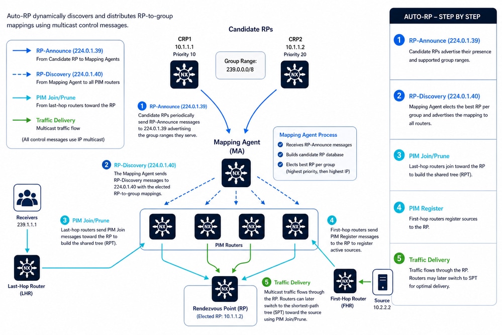
Auto-RP is a Cisco mechanism used in Protocol Independent Multicast Sparse Mode to dynamically discover and distribute Rendezvous Point (RP) information across the multicast domain. It eliminates the need for static RP configuration by using multicast-based control-plane messages to advertise, elect, and learn RP-to-group mappings. Its main components are Candidate RPs, which offer RP services for specific group ranges, and Mapping Agents, which collect candidates and decide the active RP per group.
The process begins when each Candidate RP periodically sends RP-Announce messages to 224.0.1.39, including its IP address, priority, and supported multicast group ranges. These messages are flooded throughout the network using Auto-RP listener in NX-OS, ensuring that all Mapping Agents receive them even before the network is fully operating in sparse mode.
Mapping Agents listen to these announcements, build a candidate RP database, and perform a deterministic selection process per group (typically highest priority, then highest IP address). Once the best RP is chosen, the Mapping Agent generates RP-Discovery messages and sends them to 224.0.1.40, advertising the final RP-to-group mappings to all routers in the domain.
All PIM routers receive the RP-Discovery messages and install the mappings in their local RP tables. With this information, last-hop routers (connected to receivers) send PIM Join messages toward the selected RP to build the shared tree (RPT), while first-hop routers (connected to sources) encapsulate multicast traffic in PIM Register messages to inform the RP about active sources.
As traffic flows through the RP, routers can optionally switch from the shared tree (RPT) to a shortest-path tree (SPT) using additional PIM Join/Prune signaling directly toward the source. Throughout this process, Auto-RP continuously refreshes mappings via periodic control messages, ensuring resiliency and automatic adaptation to topology or RP changes.
 Auto-RP Operation in PIM Sparse Mode (Control Plane Workflow)
Auto-RP Limitations and Operational Constraints
- Auto-RP operates only with IPv4 multicast and is not supported for IPv6 (PIM6), so IPv6 deployments require a different RP discovery mechanism.
- Auto-RP cannot coexist with BSR within the same PIM domain, because only one RP discovery mechanism can be configured in order to avoid control-plane conflicts.
- Auto-RP messages are not processed or forwarded by default on NX-OS devices, so explicit configuration is required for proper operation.
- The propagation of Auto-RP control messages depends on enabling the Auto-RP listener; otherwise, RP mapping information does not reach all routers.
- The RP announcement interval has a minimum threshold of 15 seconds, which limits how quickly RP updates can be advertised and affects convergence time.
- Auto-RP message filtering through route-maps can affect operation, because incorrect policies can block RP-to-group mappings.
- Auto-RP is disabled by default in VRF contexts, so it must be explicitly enabled in multi-VRF deployments.
-
ECMP-based multipath forwarding is enabled by default, which allows multicast traffic to use equal-cost paths for load balancing.
-
PIM neighbor authentication using IPsec AH-MD5 is supported.
-
PIM snooping is not available.
Benefits of Using Auto-RP
Auto-RP provides dynamic RP discovery and centralized RP mapping distribution for PIM Sparse Mode multicast environments. It eliminates the need for static RP configuration on every multicast router, reduces operational complexity, and improves multicast scalability. Auto-RP also supports multiple RP-Candidates, enabling automatic RP failover and redundancy. This mechanism helps maintain consistent multicast forwarding behavior, simplifies network expansion, and allows multicast routers to learn RP information automatically across the domain.
Auto-RP Mapping Agent and RP Selection Process
The selection process in Auto-RP is deterministic and primarily based on IP addresses. Unlike other protocols (such as PIMv2 BSR), Auto-RP does not use a configurable "priority" value; instead, it relies on IP address hierarchy to resolve conflicts.
Mapping Agent (MA) Selection
In Auto-RP, multiple Mapping Agents can coexist within the same network for redundancy. There is no formal election process where one turns off and another turns on; all are technically active. However, the switches in the network must decide which information to trust.
- Selection Criterion: Highest IP Address.
- The Process:
- All Mapping Agents send their RP-Discovery messages to the multicast group 224.0.1.40.
- Client switches receive these messages.
- If a switch receives Discovery messages from two different Mapping Agents containing conflicting information, the switch accepts the information from the Mapping Agent with the highest source IP address.
- Nexus Behavior: A Mapping Agent with a lower IP address typically enters a "passive" or "suppression" state upon detecting another MA with a higher IP address to prevent duplicate control traffic in the network.
Rendezvous Point (RP) Selection
This process is performed by the Mapping Agent after listening to all RP-Announce messages (sent to group 224.0.1.39) from the candidates.
When the Mapping Agent receives multiple candidates for the same multicast group, it applies these rules in order:
Rule A: Longest Prefix Match (Most Specific Mask)
If candidates announce overlapping ranges, the MA assigns the group to the RP that announced the smallest range (the longest subnet mask).
- Example:
- Candidate A announces 224.0.0.0/4 (the entire multicast range).
- Candidate B announces 224.10.20.0/24.
- Result: For group 224.10.20.5, Candidate B wins because its range is more specific.
Rule B: Highest IP Address (Tie-breaker)
If two or more candidates announce exactly the same group range, the Mapping Agent must choose only one.
- Criterion: The candidate with the highest IP address wins.
- Example:
- Candidate 1: 10.2.0.1 for range 224.10.20.0/24.
- Candidate 2: 10.2.0.4 for range 224.10.20.0/24.
- Result: The Mapping Agent select 10.2.0.4 as the official RP for that range and this is advertised in its Discovery messages.
Layer 2 Considerations: Multicast MAC and Snooping
Although the focus of this article is Layer 3 multicast using PIM, Layer 2 behavior plays a critical role in troubleshooting and overall design. At Layer 2, devices communicate using MAC addresses, which are 48-bit identifiers assigned to network interfaces, and multicast traffic requires a specific MAC addressing scheme to differentiate it from unicast and broadcast traffic.
IPv4 multicast MAC addresses are derived from Layer 3 multicast group addresses using the reserved prefix `01:00:5E`. However, only 23 bits of the IP multicast address are mapped into the MAC address, which creates a 32:1 overlap, meaning that up to 32 different multicast IP groups can map to the same MAC address. As a result, hosts listening to a given multicast MAC address can receive traffic for multiple multicast groups, even if they are interested in only one. For example, 224.1.1.1, 225.1.1.1, 226.1.1.1, 227.1.1.1, 228.1.1.1, and more.
This overlap has direct implications for network efficiency and troubleshooting. Since Layer 2 forwarding decisions based solely on MAC addresses cannot distinguish between overlapping multicast groups, switches can deliver unnecessary traffic to hosts. These hosts must then rely on higher-layer filtering (IP/IGMP) to discard unwanted packets, consuming CPU and buffer resources.
In Cisco Nexus NX-OS, this limitation is mitigated by the behavior of IGMP snooping. By default, IGMP snooping performs IP-based lookups rather than MAC-only forwarding, allowing switches to make more precise forwarding decisions even when multiple multicast groups share the same MAC address. This significantly improves Layer 2 efficiency and reduces unnecessary traffic delivery.
Auto-RP Configuration
This section provides a detailed explanation of the Auto-RP configuration, using a simple implementation as a reference. In this setup, a multicast source is connected to two Nexus switches via vPC to deliver traffic to a receiver. In this design, both N9K-1 and N9K-2 simultaneously function as RP Candidates and Mapping Agents.

Caution: PIM neighbors are not supported across a vPC port-channel.
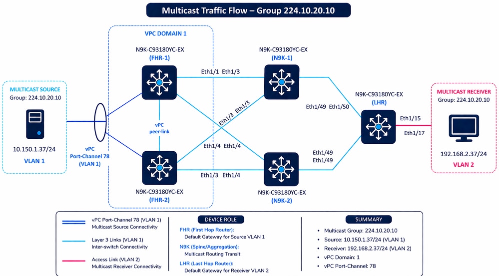 Multicast Traffic Flow
First Hop Router
The same configuration has FHR-2.
FHR-1# show running-config pim
feature pim
ip pim auto-rp forward listen

interface Vlan1
  ip pim sparse-mode

interface Ethernet1/1
  ip pim sparse-mode

interface Ethernet1/3
  ip pim sparse-mode
| Command | Purpose / Description |
|---|---|
| feature pim | Enables the PIM (Protocol Independent Multicast) process on the switch. |
| ip pim auto-rp forward listen | Enables the Auto-RP Listener. This allows the switch to receive and forward Auto-RP control messages (224.0.1.39 and 224.0.1.40) even if it does not yet know the identity of the RP. |
| ip pim sparse-mode | Enables PIM Sparse Mode on a specific interface. In this mode, multicast traffic is only forwarded to segments that have explicitly requested it via PIM Join messages. |
Mapping Agent and RP Candidate
N9K-1# show running-config pim
feature pim

ip pim auto-rp rp-candidate loopback0 group-list 224.10.20.0/24 interval 15
ip pim auto-rp mapping-agent loopback1

interface loopback0
  ip pim sparse-mode

interface loopback1
  ip pim sparse-mode

interface Ethernet1/3
  ip pim sparse-mode

interface Ethernet1/4
  ip pim sparse-mode

interface Ethernet1/49
  ip pim sparse-mode
This table provides a detailed technical breakdown of the PIM configuration for N9K-1. This configuration is replicated on N9K-2. Both switches are configured with a dual role, acting as both an RP Candidate and a Mapping Agent for the multicast domain.
| Command | Detailed Technical Explanation |
|---|---|
| feature pim | Feature Activation: Globally enables the Protocol Independent Multicast (PIM) engine on the Nexus switch. |
| ip pim auto-rp rp-candidate loopback0 group-list 224.10.20.0/24 interval 15 | RP Candidate Role: Configures this switch to "volunteer" as the Rendezvous Point (RP). Source: Uses the IP address of loopback0 Scope: It offers to handle the multicast group range 224.10.20.0/24. Interval: Sends "Announce" messages to the Mapping Agent every 15 seconds. Hold timer is three times this value. |
| ip pim auto-rp mapping-agent loopback1 | Mapping Agent Role: Configures the switch as the "administrator" of the Auto-RP process. Function: It listens to all RP Candidates, resolves conflicts (using the highest IP address as a tie-breaker), and broadcasts the "Discovery" messages to the rest of the network to inform them who the active RP is. |
| interface loopback0 / loopback1 | Logical Interfaces: PIM is enabled on these interfaces because they serve as the source IPs for the RP Candidate and Mapping Agent roles. They must be reachable via the unicast routing table from all PIM routers. |
| interface Ethernet1/3, 1/4, 1/49 | Physical Forwarding: Enables PIM Sparse Mode on physical ports. This allows the switch to form PIM neighbor adjacencies with other routers and forward multicast traffic across these specific links. |
| ip pim sparse-mode | Operational Mode: Applied to all interfaces above. It ensures that multicast traffic is only sent to receivers that have explicitly requested it via PIM Join messages, preventing unnecessary network flooding. |
Routing Configuration for IPv4 Reachability
- In this topology, all Nexus switches participate in a single OSPF process named UNDERLAY, operating within Area 0 (0.0.0.0) to provide full routing reachability across the network.
- On the LHR, OSPF is enabled on VLAN 2, which serves as the gateway for the multicast receiver, and on the uplink interfaces Ethernet1/49 and Ethernet1/50, both configured as point-to-point. This ensures efficient adjacency formation toward the upstream N9K switches without DR/BDR elections.
- The FHR layer (FHR-1 and FHR-2) shares an identical configuration. OSPF is enabled on VLAN 1, which acts as the gateway for the multicast source, and on the routed uplinks (Ethernet1/1 and Ethernet1/3) toward the aggregation layer. These links are also configured as point-to-point, optimizing convergence and adjacency behavior.
- Similarly, N9K-1 and N9K-2 have identical OSPF configurations, with the addition of Loopback0 and Loopback1 advertisment into OSPF.
- These loopbacks are critical, as they are later used for PIM RP Candidate and Mapping Agent roles.
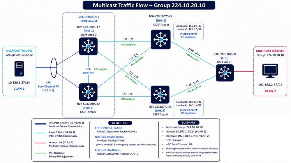 PIM Neighbors and OSPF Area 0
N9K-1 — OSPF Configuration
N9K-1(config)# show running-config ospf
feature ospf

router ospf UNDERLAY
  router-id 10.2.0.1

interface loopback0
  ip router ospf UNDERLAY area 0.0.0.0

interface loopback1
  ip router ospf UNDERLAY area 0.0.0.0

interface Ethernet1/3
  ip ospf network point-to-point
  ip router ospf UNDERLAY area 0.0.0.0

interface Ethernet1/4
  ip ospf network point-to-point
  ip router ospf UNDERLAY area 0.0.0.0

interface Ethernet1/49
  ip ospf network point-to-point
  ip router ospf UNDERLAY area 0.0.0.0
FHR-1 — OSPF Configuration
FHR-1(config)# show running-config ospf
feature ospf

router ospf UNDERLAY

interface Vlan1
  ip router ospf UNDERLAY area 0.0.0.0

interface Ethernet1/1
  ip ospf network point-to-point
  ip router ospf UNDERLAY area 0.0.0.0

interface Ethernet1/3
  ip ospf network point-to-point
  ip router ospf UNDERLAY area 0.0.0.0
LHR — OSPF Configuration
LHR(config)# show running-config ospf
feature ospf

router ospf UNDERLAY

interface Vlan2
  ip router ospf UNDERLAY area 0.0.0.0

interface Ethernet1/49
  ip ospf network point-to-point
  ip router ospf UNDERLAY area 0.0.0.0

interface Ethernet1/50
  ip ospf network point-to-point
  ip router ospf UNDERLAY area 0.0.0.0
Verify Operational State and Troubleshoot Auto-RP
Step 1: Verify Basic IP Reachability (Unicast Underlay Validation)
Before analyzing multicast behavior, it is critical to validate that the unicast underlay (OSPF Area 0) is fully operational. Multicast control-plane protocols such as PIM and Auto-RP depend on unicast reachability to function correctly.
The first validation step is to confirm that the source and receiver (or their closest Layer 3 gateways: FHR and LHR) are reachable.
From the topology:
-
FHR-1 / FHR-2 → Closest to multicast source (10.150.1.37 – VLAN 1)
-
LHR → Closest to multicast receiver (192.168.2.37 – VLAN 2)
Validation Approach
1. Perform ICMP reachability tests between:
-
FHR ↔ LHR
-
FHR ↔ Receiver subnet (VLAN 2 gateway)
-
LHR ↔ Source subnet (VLAN 1 gateway)
2. Validate source and receiver reachability in the routing table. For vPC deployments, ensure consistency across both Nexus peers. Note that the receiver has an ECMP path, whereas the source is reachable via Layer 2.
FHR-1 — Route to Source
FHR-1# show ip route 10.150.1.37

10.150.1.37/32, ubest/mbest: 1/0, attached
    *via 10.150.1.37, Vlan1, [250/0], 06:57:19, am
FHR-1 — Route to Receiver
FHR-1# show ip route 192.168.2.37

192.168.2.0/24, ubest/mbest: 2/0
    *via 10.4.0.6, Eth1/3, [110/45], 04:11:08, ospf-UNDERLAY, intra
    *via 10.4.0.10, Eth1/1, [110/45], 04:11:08, ospf-UNDERLAY, intra
FHR-2 — Route to Source
FHR-2# show ip route 10.150.1.37

10.150.1.37/32, ubest/mbest: 1/0, attached
    *via 10.150.1.37, Vlan1, [250/0], 07:03:45, am
FHR-2 — Route to Receiver
FHR-2# show ip route 192.168.2.37

192.168.2.0/24, ubest/mbest: 2/0
    *via 10.4.0.13, Eth1/3, [110/45], 04:16:16, ospf-UNDERLAY, intra
    *via 10.4.0.18, Eth1/4, [110/45], 04:16:16, ospf-UNDERLAY, intra
LHR — Route to Source
LHR(config)# show ip route 10.150.1.37

10.150.1.0/24, ubest/mbest: 2/0
    *via 10.4.0.22, Eth1/49, [110/45], 04:14:52, ospf-UNDERLAY, intra
    *via 10.4.0.26, Eth1/50, [110/45], 04:14:52, ospf-UNDERLAY, intra
LHR — Route to Receiver
LHR(config)# show ip route 192.168.2.37

192.168.2.37/32, ubest/mbest: 1/0, attached
    *via 192.168.2.37, Vlan2, [250/0], 06:47:21, am
Important Considerations
-
Failure of this test strongly indicates an underlay issue.
-
Multicast cannot function properly without unicast reachability, since:
-
PIM neighbors rely on unicast routing
-
RP (Loopback) addresses must be reachable
-
RPF (Reverse Path Forwarding) checks depend on the routing table
-
-
A successful ping does not guarantee multicast can work, because:
-
ICMP can be permitted while multicast is blocked
-
PIM or Auto-RP can still be misconfigured
-

Tip: Before analyzing Auto-RP, PIM adjacencies, or RP selection, always ensure that the underlay routing domain is stable, consistent, and fully reachable end-to-end.
Step 2: Identify Multicast Roles and End-to-End Topology
The next step is to clearly identify the role of each device involved in forwarding multicast traffic. This is a mandatory step, as multicast troubleshooting is entirely dependent on understanding the traffic flow and expected behavior across the topology.
At a minimum, these elements must be identified:
-
Multicast Source (S): 10.150.1.37 (VLAN 1)
-
Multicast Group (G): 224.10.20.10
-
Receiver: 192.168.2.37 (VLAN 2)
-
First Hop Router (FHR): FHR-1 / FHR-2 (closest to the source)
-
Last Hop Router (LHR): LHR (closest to the receiver)
Additionally, it is required to identify the control-plane roles:
-
RP Candidates: N9K-1 and N9K-2 (Loopback0)
-
Mapping Agents: N9K-1 and N9K-2 (Loopback1)
Topology and Control-Plane Awareness
A detailed network topology is mandatory to proceed with any multicast troubleshooting. This includes:
-
Physical connectivity (interfaces used between devices)
-
Logical topology (VLANs, routed links, vPC relationships)
-
Routing protocol in use (OSPF Area 0 in this design)
-
Routing domain boundaries (single IGP vs mixed protocols such as OSPF, EIGRP, or BGP)
-
Loopback interfaces used for RP and Mapping Agent roles
-
PIM-enabled interfaces and neighbor relationships
What Must Be Clearly Understood
-
The exact path from Source → FHR → RP → LHR → Receiver
-
Which devices are responsible for:
-
Sending PIM Register (FHR)
-
Building (*,G) or (S,G) trees (LHR)
-
Advertising RP information (Mapping Agent)
-
-
How routing (OSPF) ensures reachability to:
-
Source subnet
-
Receiver subnet
-
RP loopback addresses
- Mapping Aggent loopback addresses
-
Caution: Multicast troubleshooting without a clear topology is equivalent to debugging without visibility—it leads to incorrect assumptions and misdiagnosis.
Step 3: Validate Auto-RP Configuration Based on Device Role
The next step is to verify that Auto-RP is correctly configured on each device according to its role in the multicast topology. This includes confirming that:
-
RP Candidates (N9K-1 / N9K-2) are properly configured to advertise their Loopback0 as the RP for the multicast group range.
-
Mapping Agents (N9K-1 / N9K-2) are configured to collect RP-Announce messages and generate RP-Discovery messages using Loopback1.
-
FHR and LHR have PIM Sparse Mode enabled on all relevant interfaces to participate in Auto-RP and receive RP mappings.
It is essential to ensure that all required interfaces (including loopbacks and routed links) are enabled for PIM sparse-mode, and that there are no missing configurations that would prevent the exchange of RP-Announce (224.0.1.39) and RP-Discovery (224.0.1.40) messages.

Note: N9K-1 and N9K-2 are configured as RP-Candidates and Mapping Agents within the multicast domain.
Caution: Any missing or inconsistent Auto-RP configuration can prevent routers from learning the RP, resulting in multicast traffic not being forwarded correctly.
Step 4: Validate the Operation of all RP Candidates and all Mapping Agents
Step 4.1 Verify PIM Neighbor Adjacencies
The first validation step is to confirm that all expected PIM neighbors are established correctly across the multicast topology.
N9K-1 — Verify PIM Neighbors
N9K-1# show ip pim neighbor

PIM Neighbor Status for VRF "default"
Neighbor        Interface            Uptime    Expires   DR       Bidir-  BFD    ECMP Redirect
                                                         Priority Capable State     Capable
10.4.0.5        Ethernet1/3          23:19:45  00:01:20  1        yes     n/a     no
10.4.0.14       Ethernet1/4          23:19:45  00:01:38  1        yes     n/a     no
10.4.0.21       Ethernet1/49         23:19:45  00:01:38  1        yes     n/a     no
N9K-2 — Verify PIM Neighbors
N9K-2# show ip pim neighbor

PIM Neighbor Status for VRF "default"
Neighbor        Interface            Uptime    Expires   DR       Bidir-  BFD    ECMP Redirect
                                                         Priority Capable State     Capable
10.4.0.9        Ethernet1/3          23:21:18  00:01:29  1        yes     n/a     no
10.4.0.17       Ethernet1/4          23:21:18  00:01:23  1        yes     n/a     no
10.4.0.25       Ethernet1/49         23:21:18  00:01:44  1        yes     n/a     no
Validation Points
- Verify that all expected neighbors appear on every routed interface.
- Verify that neighbor uptime is stable and continuously increasing.
- Verify that the Expires timer refreshes periodically.
- Verify that no unexpected adjacency flaps occur.
- Verify the correct Designated Router (DR) election.
- Verify that multicast interfaces form PIM adjacencies successfully.
In this topology:
- N9K-1 establishes three PIM neighbors.
- N9K-2 also establishes three PIM neighbors.
- All adjacencies remain stable for more than 23 hours, which indicates stable multicast control-plane operation.
Step 4.2 Verify PIM-Enabled Interfaces
The next step is to confirm that all interfaces participating in Auto-RP are enabled for PIM.
This validation is especially important for:
- RP-Candidate loopbacks
- Mapping Agent loopbacks
N9K-1 — Verify PIM Interfaces
N9K-1# show ip pim interface brief

PIM Interface Status for VRF "default"
Interface            IP Address      PIM DR Address  Neighbor  Border
                                                     Count     Interface
Ethernet1/3          10.4.0.6        10.4.0.6        1         no
Ethernet1/4          10.4.0.13       10.4.0.14       1         no
Ethernet1/49         10.4.0.22       10.4.0.22       1         no
loopback0            10.2.0.1        10.2.0.1        0         no
loopback1            10.2.1.5        10.2.1.5        0         no
N9K-2 — Verify PIM Interfaces
N9K-2# show ip pim interface brief

PIM Interface Status for VRF "default"
Interface            IP Address      PIM DR Address  Neighbor  Border
                                                     Count     Interface
Ethernet1/3          10.4.0.10       10.4.0.10       1         no
Ethernet1/4          10.4.0.18       10.4.0.18       1         no
Ethernet1/49         10.4.0.26       10.4.0.26       1         no
loopback0            10.2.0.4        10.2.0.4        0         no
loopback1            10.2.1.4        10.2.1.4        0         no
Validation Points:
- Verify that all routed multicast interfaces appear in the output.
- Verify that RP-Candidate loopbacks are PIM-enabled.
- Verify that Mapping Agent loopbacks are PIM-enabled.
- Verify that neighbor counts are correct on transit interfaces.
- Verify that loopback interfaces correctly show Neighbor Count = 0.
Loopback Role Assignment:
| Device | Function | Loopback |
|---|---|---|
| N9K-1 | RP-Candidate | 10.2.0.1 |
| N9K-1 | Mapping Agent | 10.2.1.5 |
| N9K-2 | RP-Candidate | 10.2.0.4 |
| N9K-2 | Mapping Agent | 10.2.1.4 |
The loopbacks correctly appear as active PIM interfaces even though they do not form PIM neighbors. This behavior is expected because loopback interfaces do not establish multicast adjacencies directly.
The presence of these loopbacks confirms that:
- PIM can source Auto-RP control messages correctly.
- RP advertisements can be originated successfully.
- Mapping Agent functionality can operate properly.
Step 4.3 Analyze show ip pim rp
This command validates:
- RP discovery
- Auto-RP advertisements
- Mapping Agent operation
- Group-to-RP mappings
N9K-1 — RP Information
N9K-1# show ip pim rp

PIM RP Status Information for VRF "default"
BSR disabled
Auto-RP RPA: 10.2.1.5*, next Discovery message in: 00:00:39
BSR RP Candidate policy: None
BSR RP policy: None
Auto-RP Announce policy: None
Auto-RP Discovery policy: None

RP: 10.2.0.1*, (0),
 uptime: 22:18:44   priority: 255,
 RP-source: 10.2.0.1 (A),
 group ranges:
 224.10.20.0/24   , expires: 00:00:37 (A)

RP: 10.2.0.4, (0),
 uptime: 23:00:32   priority: 255,
 RP-source: 10.2.0.4 (A),
 group ranges:
 224.10.20.0/24   , expires: 00:00:44 (A)
Line-by-Line Explanation
BSR disabled
BSR disabled
This confirms that:
- Bootstrap Router (BSR) is not used.
- The multicast domain relies exclusively on Auto-RP.
This behavior is expected in this topology.
Auto-RP RPA: 10.2.1.5*
Auto-RP RPA: 10.2.1.5*
- 10.2.1.5 corresponds to loopback1 on N9K-1.
- The * indicates that the local switch itself is the active Mapping Agent.
This means:
- N9K-1 originates RP-Discovery messages.
- N9K-1 collects RP announcements from RP-Candidates.
- N9K-1 distributes RP mapping information to the multicast domain.
Next Discovery message in
next Discovery message in: 00:00:39
- Verify that the timer continuously refreshes.
- Verify that Discovery messages are sent periodically.
If this timer freezes or expires unexpectedly, Auto-RP advertisements cannot propagate correctly.
Policy Fields
BSR RP Candidate policy: None
BSR RP policy: None
Auto-RP Announce policy: None
Auto-RP Discovery policy: None
- No filtering policies are applied.
- All RP announcements and Discovery advertisements are accepted.
First RP Entry
RP: 10.2.0.1*, (0),
- RP address = 10.2.0.1
- The * indicates that this RP is local to N9K-1.
- 10.2.0.1 corresponds to loopback0 on N9K-1.
This confirms that N9K-1 is configured as an RP-Candidate.
Uptime and Priority
uptime: 22:18:44 priority: 255,
- Stable uptime indicates stable RP advertisement operation.
- Priority 255 is the default highest priority.
RP Source
RP-source: 10.2.0.1 (A),
- The RP advertisement originated directly from the RP itself.
- (A) indicates Auto-RP learned information.
Group Range
224.10.20.0/24
- Verify that the correct multicast range is advertised.
- Verify that the group range matches the configuration.
Second RP Entry
RP: 10.2.0.4, (0),
- Another RP exists in the topology.
- 10.2.0.4 corresponds to loopback0 on N9K-2.
- No * appears because this RP is remote from N9K-1.
N9K-2 — RP Information
N9K-2# show ip pim rp

PIM RP Status Information for VRF "default"
BSR disabled
Auto-RP RPA: 10.2.1.5, uptime: 22:19:10, expires: 00:02:28

RP: 10.2.0.4*, (0),
 uptime: 23:14:14   priority: 255,
 RP-source: 10.2.1.5 (A),
 group ranges:
 224.10.20.0/24   , expires: 00:02:28 (A)
Key Differences on N9K-2
Auto-RP RPA: 10.2.1.5
- No * appears because N9K-2 is not the Mapping Agent.
- N9K-2 learns Mapping Agent information remotely from N9K-1.
Important RP Difference
RP-source: 10.2.1.5 (A),
- N9K-2 learns RP information from the Mapping Agent.
- The Mapping Agent is 10.2.1.5.
This confirms that:
- Auto-RP Discovery messages are functioning correctly.
- Mapping Agent advertisements propagate successfully through the multicast domain.
Step 4.4 Validate Auto-RP Election Process and RP Selection
Auto-RP uses two different multicast control-plane functions:
- RP-Candidate
- Mapping Agent
Understanding how these functions interact is critical when validating multicast operation in a PIM Sparse Mode environment.
In this topology:
- N9K-1 and N9K-2 operate as RP-Candidates.
- N9K-1 operates as the active Mapping Agent.
RP-Candidate Operation
An RP-Candidate advertises itself as a valid Rendezvous Point for one or more multicast group ranges.
Each RP-Candidate periodically sends Auto-RP Announce messages to:
- 224.0.1.39 — Auto-RP Announce group
These announcements contain:
- RP address
- Group range
- Priority
- Holdtime
In this topology:
- 10.2.0.1 on N9K-1 advertises itself as an RP.
- 10.2.0.4 on N9K-2 advertises itself as an RP.
N9K-1 — RP-Candidate Information
N9K-1# show ip pim rp
<snip>
RP: 10.2.0.1*, (0),
 uptime: 23:11:22 priority: 255,
 RP-source: 10.2.0.1 (A),
 group ranges:
 224.10.20.0/24 , expires: 00:00:38 (A)

RP: 10.2.0.4, (0),
 uptime: 23:53:09 priority: 255,
 RP-source: 10.2.0.4 (A),
 group ranges:
 224.10.20.0/24 , expires: 00:00:43 (A)
N9K-2 — RP-Candidate Information
N9K-2# show ip pim rp
<snip>
RP: 10.2.0.4*, (0),
 uptime: 1d00h priority: 255,
 RP-source: 10.2.1.5 (A),
 group ranges:
 224.10.20.0/24 , expires: 00:02:52 (A)
Both devices advertise the same multicast group range:
- 224.10.20.0/24
Both RP-Candidates also use:
- Priority 255
This is important because Auto-RP uses priority and RP address during RP selection.
Active Mapping Agent Identification
The Mapping Agent selects the active RP for a multicast group starting with this logic:
- Highest RP priority wins.
- If priorities are equal, the highest RP IP address wins.
In this topology:
- N9K-1 RP address = 10.2.0.1
- N9K-2 RP address = 10.2.0.4
- Both RP-Candidates use priority 255
Because both RP-Candidates have the same priority:
- The highest RP IP address becomes the selected RP.
Therefore:
- 10.2.0.4 becomes the active RP for 224.10.20.0/24.
Selected RP Validation
N9K-2 — Selected RP
N9K-2# show ip pim rp
<snip>
RP: 10.2.0.4*, (0),
 uptime: 23:14:14   priority: 255,
 RP-source: 10.2.1.5 (A),
 group ranges:
 224.10.20.0/24
Why N9K-1 Still Displays Both RP Entries
On N9K-1:
N9K-1# show ip pim rp
<snip>
RP: 10.2.0.1*, (0),
RP: 10.2.0.4, (0),
This behavior is expected because:
- N9K-1 operates as the Mapping Agent.
- The Mapping Agent maintains visibility of all RP-Candidates.
- The output displays all learned RP announcements before final RP selection is distributed.
Caution: On the Mapping Agent, all RP-Candidates within the same multicast domain must appear. If any RP-Candidate is missing, verify reachability by sending a ping to the RP-Candidate IP address sourced from the Mapping Agent IP address, typically a loopback interface.
Step 5: Verify Reachability to RP-Candidates and Mapping Agents
All multicast routers participating in the PIM Sparse Mode domain must maintain stable IP reachability to:
- All RP-Candidates
- All Mapping Agents
This validation is critical because PIM Sparse Mode relies on unicast routing to:
- Reach the Rendezvous Point (RP)
- Build the shared multicast tree (RPT)
- Deliver PIM Register messages from the First Hop Router (FHR)
- Receive Auto-RP Discovery advertisements
- Perform Reverse Path Forwarding (RPF) validation
If reachability toward the RP or Mapping Agent fails:
- Multicast sources can fail to register successfully.
- Receivers can fail to join multicast groups.
- Auto-RP advertisements could not propagate correctly.
- RPF failures could occur.
- Multicast traffic forwarding can become unstable or intermittent.
Verify Stable Routing Entries
The routing table must contain stable unicast routes toward:
- All RP loopbacks
- All Mapping Agent loopbacks
- All multicast transit interfaces
The routes must remain continuously installed without route flapping or excessive reconvergence events.
Verify:
- Correct next-hop selection
- Correct outgoing interface
- Stable route uptime
- Expected routing protocol source
- Consistent unicast reachability across the multicast domain
FHR-1 — Route to RP-Candidate 10.2.0.1
FHR-1# show ip route 10.2.0.1

IP Route Table for VRF "default"
'*' denotes best ucast next-hop
'**' denotes best mcast next-hop
'[x/y]' denotes [preference/metric]
'%<string>' in via output denotes VRF <string>

10.2.0.1/32, ubest/mbest: 1/0
    *via 10.4.0.6, Eth1/3, [110/5], 1d02h, ospf-UNDERLAY, intra
FHR-1 — Route to RP-Candidate 10.2.0.4
FHR-1# show ip route 10.2.0.4

IP Route Table for VRF "default"
'*' denotes best ucast next-hop
'**' denotes best mcast next-hop
'[x/y]' denotes [preference/metric]
'%<string>' in via output denotes VRF <string>

10.2.0.4/32, ubest/mbest: 1/0
    *via 10.4.0.10, Eth1/1, [110/5], 1d02h, ospf-UNDERLAY, intra
FHR-1 — Route to Mapping Agent 10.2.1.5
FHR-1# show ip route 10.2.1.5

IP Route Table for VRF "default"
'*' denotes best ucast next-hop
'**' denotes best mcast next-hop
'[x/y]' denotes [preference/metric]
'%<string>' in via output denotes VRF <string>

10.2.1.5/32, ubest/mbest: 1/0
    *via 10.4.0.6, Eth1/3, [110/5], 1d02h, ospf-UNDERLAY, intra
FHR-1 — Route to Mapping Agent 10.2.1.4
FHR-1# show ip route 10.2.1.4

IP Route Table for VRF "default"
'*' denotes best ucast next-hop
'**' denotes best mcast next-hop
'[x/y]' denotes [preference/metric]
'%<string>' in via output denotes VRF <string>

10.2.1.4/32, ubest/mbest: 1/0
    *via 10.4.0.10, Eth1/1, [110/5], 1d02h, ospf-UNDERLAY, intra
FHR-2 — Route to RP-Candidate 10.2.0.1
FHR-2# show ip route 10.2.0.1

IP Route Table for VRF "default"
'*' denotes best ucast next-hop
'**' denotes best mcast next-hop
'[x/y]' denotes [preference/metric]
'%<string>' in via output denotes VRF <string>

10.2.0.1/32, ubest/mbest: 1/0
    *via 10.4.0.13, Eth1/3, [110/5], 1d02h, ospf-UNDERLAY, intra
FHR-2 — Route to RP-Candidate 10.2.0.4
FHR-2# show ip route 10.2.0.4

IP Route Table for VRF "default"
'*' denotes best ucast next-hop
'**' denotes best mcast next-hop
'[x/y]' denotes [preference/metric]
'%<string>' in via output denotes VRF <string>

10.2.0.4/32, ubest/mbest: 1/0
    *via 10.4.0.18, Eth1/4, [110/5], 1d02h, ospf-UNDERLAY, intra
FHR-2 — Route to Mapping Agent 10.2.1.5
FHR-2# show ip route 10.2.1.5

IP Route Table for VRF "default"
'*' denotes best ucast next-hop
'**' denotes best mcast next-hop
'[x/y]' denotes [preference/metric]
'%<string>' in via output denotes VRF <string>

10.2.1.5/32, ubest/mbest: 1/0
    *via 10.4.0.13, Eth1/3, [110/5], 1d02h, ospf-UNDERLAY, intra
FHR-2 — Route to Mapping Agent 10.2.1.4
FHR-2# show ip route 10.2.1.4

IP Route Table for VRF "default"
'*' denotes best ucast next-hop
'**' denotes best mcast next-hop
'[x/y]' denotes [preference/metric]
'%<string>' in via output denotes VRF <string>

10.2.1.4/32, ubest/mbest: 1/0
    *via 10.4.0.18, Eth1/4, [110/5], 1d02h, ospf-UNDERLAY, intra
LHR — Route to RP-Candidate 10.2.0.1
LHR# show ip route 10.2.0.1

IP Route Table for VRF "default"
'*' denotes best ucast next-hop
'**' denotes best mcast next-hop
'[x/y]' denotes [preference/metric]
'%<string>' in via output denotes VRF <string>

10.2.0.1/32, ubest/mbest: 1/0
    *via 10.4.0.22, Eth1/49, [110/2], 1d02h, ospf-UNDERLAY, intra
LHR — Route to RP-Candidate 10.2.0.4
LHR# show ip route 10.2.0.4

IP Route Table for VRF "default"
'*' denotes best ucast next-hop
'**' denotes best mcast next-hop
'[x/y]' denotes [preference/metric]
'%<string>' in via output denotes VRF <string>

10.2.0.4/32, ubest/mbest: 1/0
    *via 10.4.0.26, Eth1/50, [110/2], 1d02h, ospf-UNDERLAY, intra
LHR — Route to Mapping Agent 10.2.1.5
LHR# show ip route 10.2.1.5

IP Route Table for VRF "default"
'*' denotes best ucast next-hop
'**' denotes best mcast next-hop
'[x/y]' denotes [preference/metric]
'%<string>' in via output denotes VRF <string>

10.2.1.5/32, ubest/mbest: 1/0
    *via 10.4.0.22, Eth1/49, [110/2], 1d02h, ospf-UNDERLAY, intra
LHR — Route to Mapping Agent 10.2.1.4
LHR# show ip route 10.2.1.4

IP Route Table for VRF "default"
'*' denotes best ucast next-hop
'**' denotes best mcast next-hop
'[x/y]' denotes [preference/metric]
'%<string>' in via output denotes VRF <string>

10.2.1.4/32, ubest/mbest: 1/0
    *via 10.4.0.26, Eth1/50, [110/2], 1d02h, ospf-UNDERLAY, intra
Verify Ping Reachability from PIM Interfaces
After validating the routing table, verify end-to-end IP reachability toward:
- All RP-Candidates
- All Mapping Agents
The ping must be sourced from:
- PIM-enabled interfaces
- Loopback interfaces participating in multicast routing
This validation is important because multicast routers use these source addresses during:
- PIM neighbor establishment
- RPF calculations
- PIM Register encapsulation
- Auto-RP communication
Tip: If unnumbered interfaces are used, where multiple Layer 3 interfaces share the same IP address from a loopback interface, reachability verification becomes simpler because a single source IP address can be used consistently.
Ping Validation Summary
| Device | Source IP | Destination | Function | Result |
|---|---|---|---|---|
| FHR-1 | 10.4.0.5 | 10.2.0.1 | RP-Candidate | Successful |
| FHR-1 | 10.4.0.5 | 10.2.0.4 | RP-Candidate | Successful |
| FHR-1 | 10.4.0.5 | 10.2.1.5 | Mapping Agent | Successful |
| FHR-1 | 10.4.0.5 | 10.2.1.4 | Mapping Agent | Successful |
| FHR-2 | 10.4.0.9 | 10.2.0.1 | RP-Candidate | Successful |
| FHR-2 | 10.4.0.9 | 10.2.0.4 | RP-Candidate | Successful |
| FHR-2 | 10.4.0.9 | 10.2.1.5 | Mapping Agent | Successful |
| FHR-2 | 10.4.0.9 | 10.2.1.4 | Mapping Agent | Successful |
| LHR | 10.4.0.5 | 10.2.0.1 | RP-Candidate | Successful |
| LHR | 10.4.0.5 | 10.2.0.4 | RP-Candidate | Successful |
| LHR | 10.4.0.5 | 10.2.1.5 | Mapping Agent | Successful |
| LHR | 10.4.0.5 | 10.2.1.4 | Mapping Agent | Successful |
Verify Operational State and Multicast Traffic Forwarding on the FHR and LHR
The next validation step is to verify that:
- The FHR and LHR learned the expected RP successfully.
- The multicast routing table contains the expected multicast states.
- The multicast control-plane operates correctly before multicast traffic transmission begins.
- PIM Sparse Mode builds the expected shared tree state.
Step 1 Verify RP Learning on the FHR and LHR
Before validating multicast forwarding state, verify that all multicast routers learned the expected RP for the multicast group under validation.
This step is critical because:
- The FHR must know where to send PIM Register messages.
- The LHR must know which RP to use when building the shared tree.
- The multicast domain must maintain a consistent RP mapping.
In this topology:
- The selected RP is 10.2.0.4.
- The Mapping Agent is 10.2.1.5.
- The multicast group range is 224.10.20.0/24.
FHR-1 — Verify Learned RP
FHR-1# show ip pim rp

PIM RP Status Information for VRF "default"
BSR disabled
Auto-RP RPA: 10.2.1.5, uptime: 1d02h, expires: 00:02:30
BSR RP Candidate policy: None
BSR RP policy: None
Auto-RP Announce policy: None
Auto-RP Discovery policy: None

RP: 10.2.0.4, (0),
 uptime: 1d03h   priority: 255,
 RP-source: 10.2.1.5 (A),
 group ranges:
 224.10.20.0/24   , expires: 00:02:30 (A)
FHR-2 — Verify Learned RP
FHR-2# show ip pim rp

PIM RP Status Information for VRF "default"
BSR disabled
Auto-RP RPA: 10.2.1.5, uptime: 1d02h, expires: 00:02:15
BSR RP Candidate policy: None
BSR RP policy: None
Auto-RP Announce policy: None
Auto-RP Discovery policy: None

RP: 10.2.0.4, (0),
 uptime: 1d03h   priority: 255,
 RP-source: 10.2.1.5 (A),
 group ranges:
 224.10.20.0/24   , expires: 00:02:15 (A)
LHR — Verify Learned RP
LHR# show ip pim rp

PIM RP Status Information for VRF "default"
BSR disabled
Auto-RP RPA: 10.2.1.5, uptime: 1d02h, expires: 00:02:07
BSR RP Candidate policy: None
BSR RP policy: None
Auto-RP Announce policy: None
Auto-RP Discovery policy: None

RP: 10.2.0.4, (0),
 uptime: 1d03h   priority: 255,
 RP-source: 10.2.1.5 (A),
 group ranges:
 224.10.20.0/24   , expires: 00:02:07 (A)
RP Learning Analysis
The outputs confirm that:
- All multicast routers learned the same RP consistently.
- The selected RP is 10.2.0.4.
- The RP mapping was learned through Auto-RP.
- The Mapping Agent distributing the RP information is 10.2.1.5.
- The RP mapping remains stable for more than one day.
- The Discovery expiration timers refresh correctly.
This behavior is expected because:
- 10.2.0.4 was selected as the active RP during the Auto-RP election process.
- 10.2.1.5 operates as the Mapping Agent.
- All multicast routers successfully receive Auto-RP Discovery advertisements.
At this stage, the multicast control-plane is operating correctly and all routers have a consistent RP mapping for 224.10.20.0/24
Step 2 Verify Multicast Routing State Before Active Multicast Traffic
The next step is to validate the multicast routing table before multicast traffic transmission begins.
In this scenario:
- The multicast receiver already joined the multicast group.
- No active multicast source traffic is flowing yet.
This state is important because it validates:
- IGMP membership operation
- PIM shared-tree creation
- Initial (*,G) multicast state
- Receiver interest propagation
FHR-1 — Multicast Routing Table
FHR-1# show ip mroute

IP Multicast Routing Table for VRF "default"

(*, 232.0.0.0/8), uptime: 23:07:34, pim ip
  Incoming interface: Null, RPF nbr: 0.0.0.0
  Outgoing interface list: (count: 0)
FHR-2 — Multicast Routing Table
FHR-2# show ip mroute

IP Multicast Routing Table for VRF "default"

(*, 232.0.0.0/8), uptime: 23:07:37, pim ip
  Incoming interface: Null, RPF nbr: 0.0.0.0
  Outgoing interface list: (count: 0)
FHR Multicast State Analysis
The FHRs do not yet contain:
- (* ,G) state for 224.10.20.10
- (S,G) state for the multicast source
This behavior is expected because:
- No multicast source traffic is active yet.
- No PIM Register messages have been generated.
- The FHR has not started multicast forwarding.
The only multicast entry present is:
- 232.0.0.0/8
This corresponds to the default SSM range and is automatically installed by the system.
These values are expected:
- Incoming interface: Null
- RPF neighbor: 0.0.0.0
- Outgoing interface count: 0
This entry does not indicate active multicast forwarding.
LHR — Multicast Routing Table
LHR# show ip mroute

IP Multicast Routing Table for VRF "default"

(*, 224.10.20.10/32), uptime: 23:07:39, igmp ip pim
  Incoming interface: Ethernet1/50, RPF nbr: 10.4.0.26
  Outgoing interface list: (count: 1)
    Vlan2, uptime: 23:07:39, igmp

(*, 232.0.0.0/8), uptime: 23:07:39, pim ip
  Incoming interface: Null, RPF nbr: 0.0.0.0
  Outgoing interface list: (count: 0)
LHR Multicast State Analysis
Unlike the FHRs, the LHR contains an active (*,G) entry for:
- 224.10.20.10
This behavior is expected because:
- The multicast receiver already joined the group.
- IGMP membership information was learned on Vlan2.
- The LHR initiated the shared-tree join toward the RP.
The multicast routing table confirms:
- The Incoming Interface (IIF) is Ethernet1/50.
- The RPF neighbor is 10.4.0.26.
- The Outgoing Interface List (OIL) contains Vlan2.
This indicates that:
- The LHR correctly built the shared tree toward the RP.
- The multicast receiver interest propagated successfully upstream.
- PIM Join messages were transmitted correctly.
At this stage:
- No multicast source traffic is active yet.
- No (S,G) state exists yet.
- Only shared-tree state exists.
N9K-1 — Mapping Agent Multicast Routing Table
N9K-1# show ip mroute

IP Multicast Routing Table for VRF "default"

(*, 232.0.0.0/8), uptime: 1d03h, pim ip
  Incoming interface: Null, RPF nbr: 0.0.0.0
  Outgoing interface list: (count: 0)
Mapping Agent Multicast State Analysis
N9K-1 operates as the Mapping Agent only and does not participate in multicast forwarding for 224.10.20.10
Therefore, the absence of (* ,G) entrie and (S,G) entries is expected.
The Mapping Agent only distributes RP mapping information and does not necessarily participate in multicast data forwarding unless multicast traffic traverses the device directly.
N9K-2 — RP Multicast Routing Table
N9K-2# show ip mroute

IP Multicast Routing Table for VRF "default"

(*, 224.10.20.10/32), uptime: 1d01h, pim ip
  Incoming interface: loopback0, RPF nbr: 10.2.0.4
  Outgoing interface list: (count: 1)
    Ethernet1/49, uptime: 1d01h, pim

(*, 232.0.0.0/8), uptime: 1d03h, pim ip
  Incoming interface: Null, RPF nbr: 0.0.0.0
  Outgoing interface list: (count: 0)
RP Multicast State Analysis
N9K-2 operates as the active RP for:
- 224.10.20.0/24
Therefore, the RP contains the shared-tree (*,G) state for 224.10.20.10
These values are expected:
- Incoming interface = loopback0
- RPF neighbor = 10.2.0.4
- Outgoing interface = Ethernet1/49
This indicates that:
- The RP installed the shared-tree state successfully.
- The RP received PIM Join messages from downstream routers.
- The shared multicast tree toward receivers was built correctly.
At this stage:
- The RP contains only shared-tree state.
- No multicast source traffic is active yet.
- No (S,G) entries exist yet.
Step 3 Verify Multicast Routing State With Active Multicast Traffic
Once multicast traffic transmission begins, the multicast routing table transitions from shared-tree state to active source-specific forwarding state.
In this scenario:
- The multicast source is 10.150.1.37.
- The multicast group is 224.10.20.10.
- The active RP is 10.2.0.4 on N9K-2.
- The multicast source connects through vPC port-channel 78.
Important vPC Multicast Considerations
The multicast source connects through a vPC domain formed by FHR-1 and FHR-2.
Because the source connects through a vPC member port-channel:
- Traffic hashing can forward multicast packets toward either Nexus switch.
- Both FHRs require identical multicast configuration.
- Both FHRs require consistent unicast routing information.
- Both FHRs must maintain identical RP mappings.
- Both FHRs must maintain stable PIM adjacencies.
In this specific scenario:
- The multicast flow hashes toward FHR-2.
- FHR-2 becomes the active forwarding FHR for the multicast source.
FHR-1 — Multicast Routing Table
FHR-1# show ip mroute

IP Multicast Routing Table for VRF "default"

(10.150.1.37/32, 224.10.20.10/32), uptime: 00:03:58, ip pim
  Incoming interface: Vlan1, RPF nbr: 10.150.1.37
  Outgoing interface list: (count: 0)

(*, 232.0.0.0/8), uptime: 1d00h, pim ip
  Incoming interface: Null, RPF nbr: 0.0.0.0
  Outgoing interface list: (count: 0)
FHR-1 — vPC Role
FHR-1# show vpc role

vPC Role status
----------------------------------------------------
vPC role                        : primary <<<
Dual Active Detection Status    : 0
vPC system-mac                  : 00:23:04:ee:be:01
vPC system-priority             : 32667
vPC local system-mac            : 00:6b:f1:84:02:97
vPC local role-priority         : 32667
vPC local config role-priority  : 32667
vPC peer system-mac             : 6c:b2:ae:ee:5a:97
vPC peer role-priority          : 32667
vPC peer config role-priority   : 32667
FHR-1 Multicast State Analysis
FHR-1 contains an active (S,G) entry for:
- Source = 10.150.1.37
- Group = 224.10.20.10
The multicast routing entry confirms:
- The source was learned on Vlan1.
- The RPF neighbor is the directly connected multicast source.
- No outgoing interfaces exist in the OIL.
This behavior is expected because the multicast flow did not hash toward FHR-1 for outbound forwarding.
As a result:
- FHR-1 installs local source state only.
- FHR-1 does not forward multicast traffic upstream through PIM.
FHR-2 — Multicast Routing Table
FHR-2# show ip mroute

IP Multicast Routing Table for VRF "default"

(10.150.1.37/32, 224.10.20.10/32), uptime: 00:16:35, ip pim
  Incoming interface: Vlan1, RPF nbr: 10.150.1.37
  Outgoing interface list: (count: 1)
    Ethernet1/3, uptime: 00:16:35, pim

(*, 232.0.0.0/8), uptime: 1d00h, pim ip
  Incoming interface: Null, RPF nbr: 0.0.0.0
  Outgoing interface list: (count: 0)
FHR-2 — vPC Role
FHR-2# show vpc role

vPC Role status
----------------------------------------------------
vPC role                        : secondary <<<
Dual Active Detection Status    : 0
vPC system-mac                  : 00:23:04:ee:be:01
vPC system-priority             : 32667
vPC local system-mac            : 6c:b2:ae:ee:5a:97
vPC local role-priority         : 32667
vPC local config role-priority  : 32667
vPC peer system-mac             : 00:6b:f1:84:02:97
vPC peer role-priority          : 32667
vPC peer config role-priority   : 32667
FHR-2 Multicast State Analysis
Unlike FHR-1, FHR-2 contains:
- An active outgoing interface list
- An active PIM forwarding path
This indicates that:
- FHR-2 became the operational forwarding FHR for the multicast flow.
- The multicast packets hashed toward FHR-2 through the vPC member port-channel.
- FHR-2 encapsulated the multicast traffic into PIM Register messages.
- FHR-2 forwarded multicast traffic upstream toward the RP.
ECMP and Multicast Forwarding Behavior
The outgoing interface Ethernet1/3 matches the unicast routing table toward the receiver 192.168.2.37
FHR-2 — Route to Multicast Receiver
FHR-2# show ip route 192.168.2.37

IP Route Table for VRF "default"

'*' denotes best ucast next-hop
'**' denotes best mcast next-hop
'[x/y]' denotes [preference/metric]
'%<string>' in via output denotes VRF <string>

192.168.2.0/24, ubest/mbest: 2/0
    *via 10.4.0.13, Eth1/3, [110/45], 1d02h, ospf-UNDERLAY, intra
    *via 10.4.0.18, Eth1/4, [110/45], 1d02h, ospf-UNDERLAY, intra
FHR-2 contains two equal-cost routes toward the multicast receiver subnet:
- 10.4.0.13 through Ethernet1/3
- 10.4.0.18 through Ethernet1/4
This confirms that:
- ECMP routing is active in the multicast transport topology.
- Multiple valid unicast forwarding paths exist toward the receiver network.
- PIM can use the MRIB-selected RPF path for multicast forwarding decisions.
- Packet duplication across parallel ECMP paths does not occur.
Although two equal-cost routes exist, multicast forwarding uses a single RPF path for each multicast flow.
In this topology, the multicast flow uses:
- Ethernet1/3 toward 10.4.0.13
This behavior matches the multicast routing table observed previously:
(10.150.1.37/32, 224.10.20.10/32)
  Outgoing interface list:
    Ethernet1/3
vPC Operational Primary and Secondary Behavior
The vPC operational roles influence multicast forwarding behavior differently for:
- PIM traffic
- IGMP processing
In this topology:
- FHR-1 is the operational vPC primary.
- FHR-2 is the operational vPC secondary.
Both Nexus switches can:
- Process PIM control-plane traffic
- Build multicast routing state
- Forward multicast traffic through PIM
However:
- Only the operational vPC primary processes IGMP receiver traffic toward the access layer.
This distinction is important because:
- PIM forwarding toward the routed network remains active on both peers.
- IGMP forwarding toward Layer 2 receiver segments remains centralized on the operational primary.
Therefore:
- Multicast traffic from the source toward the routed multicast domain can exit through either vPC peer.
- Multicast traffic toward IGMP receivers relies on the operational primary behavior.
LHR — Multicast Routing Table
LHR# show ip mroute

IP Multicast Routing Table for VRF "default"

(*, 224.10.20.10/32), uptime: 1d00h, igmp ip pim
  Incoming interface: Ethernet1/50, RPF nbr: 10.4.0.26
  Outgoing interface list: (count: 1)
    Vlan2, uptime: 1d00h, igmp

(10.150.1.37/32, 224.10.20.10/32), uptime: 00:06:31, ip mrib pim
  Incoming interface: Ethernet1/49, RPF nbr: 10.4.0.22
  Outgoing interface list: (count: 1)
    Vlan2, uptime: 00:06:31, mrib

(*, 232.0.0.0/8), uptime: 1d00h, pim ip
  Incoming interface: Null, RPF nbr: 0.0.0.0
  Outgoing interface list: (count: 0)
LHR Multicast State Analysis
The LHR now contains both:
- (* ,G) shared-tree state
- (S,G) source-tree state
This confirms:
- The multicast receiver joined successfully.
- The multicast source became active.
- The LHR transitioned from shared-tree forwarding to source-tree forwarding.
The (S,G) entry confirms:
- The multicast source path was learned successfully.
- The RPF neighbor is 10.4.0.22.
- The multicast traffic arrives through Ethernet1/49.
- The multicast traffic forwards toward Vlan2 receivers.
This behavior confirms successful:
- PIM forwarding
- RPF validation
- Source-tree construction
- Multicast traffic delivery
N9K-1 — Transit Multicast Routing Table
N9K-1# show ip mroute

IP Multicast Routing Table for VRF "default"

(10.150.1.37/32, 224.10.20.10/32), uptime: 00:06:42, pim ip
  Incoming interface: Ethernet1/4, RPF nbr: 10.4.0.14
  Outgoing interface list: (count: 1)
    Ethernet1/49, uptime: 00:06:42, pim

(*, 232.0.0.0/8), uptime: 1d04h, pim ip
  Incoming interface: Null, RPF nbr: 0.0.0.0
  Outgoing interface list: (count: 0)
N9K-1 Transit State Analysis
N9K-1 operates as a transit multicast router for the active multicast flow.
The multicast routing entry confirms:
- The multicast traffic arrives from Ethernet1/4.
- The multicast traffic forwards toward Ethernet1/49.
- The multicast forwarding path toward the LHR is operational.
This confirms successful:
- PIM neighbor operation
- RPF validation
- Multicast forwarding across the transit network
N9K-2 — RP Multicast Routing Table
N9K-2# show ip mroute

IP Multicast Routing Table for VRF "default"

(*, 224.10.20.10/32), uptime: 1d02h, pim ip
  Incoming interface: loopback0, RPF nbr: 10.2.0.4
  Outgoing interface list: (count: 1)
    Ethernet1/49, uptime: 1d02h, pim

(10.150.1.37/32, 224.10.20.10/32), uptime: 00:06:50, ip pim mrib
  Incoming interface: Ethernet1/4, RPF nbr: 10.4.0.17, internal
  Outgoing interface list: (count: 0)

(*, 232.0.0.0/8), uptime: 1d04h, pim ip
  Incoming interface: Null, RPF nbr: 0.0.0.0
  Outgoing interface list: (count: 0)
RP Multicast State Analysis
N9K-2 operates as the active RP for the multicast group.
The RP contains both:
- (* ,G) shared-tree state
- (S,G) source-tree state
The absence of outgoing interfaces in the (S,G) entry is expected because:
- The RP already switched receivers toward the shortest-path tree.
- The shared-tree forwarding path is no longer required for active multicast forwarding.
Minimum Multicast Information Required for RCA and Health Diagnostics
The list of commands provides the minimum recommended multicast data collection required to perform a proper Root Cause Analysis (RCA) or multicast health diagnostic on Cisco Nexus 9000 Series switches running NX-OS. These outputs capture multicast control-plane state, MRIB programming, forwarding information, vPC operational state, and hardware forwarding details. However, additional information can still be required depending on the failure scenario. For example, multicast packet loss, intermittent traffic drops, packet replication problems, hardware forwarding inconsistencies, or out-of-order multicast forwarding often require direct packet captures on the Nexus switch using Ethanalyzer, SPAN, or hardware-level captures. Similarly, transient RPF inconsistencies, ECMP forwarding changes, ASIC programming failures, or IGMP suppression events can occur without persistent log generation.
As a result, combining show tech outputs with packet captures and forwarding validation significantly improves diagnostic accuracy and RCA quality. Although this information provides a strong operational baseline for multicast troubleshooting, it does not guarantee that an RCA can always be identified exclusively from these outputs. Certain multicast failures require additional troubleshooting, live traffic analysis, hardware-level validation, topology correlation, or extended packet captures to isolate the exact root cause.
Tip: Collecting this information during the working and non-working provides a clear snapshot of how the issue appears from the Nexus perspective and significantly improves the ability to identify the root cause.
Minimum Multicast Data Collection Commands
N9K-1# show tech-support multicast >> bootflash:$(SWITCHNAME)-sh-tech-multicast.txt

N9K-1# show tech-support details >> bootflash:$(SWITCHNAME)-sh-tech-det.txt

N9K-1# show tech-support vpc >> bootflash:$(SWITCHNAME)-sh-tech-vpc.txt

N9K-1# show tech-support forwarding multicast >> bootflash:$(SWITCHNAME)-sh-tech-fwd-multicast.txt

N9K-1# show tech-support forwarding l3 multicast detail vdc-all >> bootflash:$(SWITCHNAME)-sh-tech-fwd-l3-multicast.txt

N9K-1# show tech-support forwarding l3 unicast detail vdc-all >> bootflash:$(SWITCHNAME)-sh-tech-fwd-l3-unicast-det.txt
Create a TAR Archive for Export
After generating the show tech files, consolidate them into a single TAR archive for export and analysis. The command is a single line.
N9K-1# tar create bootflash:$(SWITCHNAME)-multicast-logs
bootflash:$(SWITCHNAME)-sh-tech-multicast.txt
bootflash:$(SWITCHNAME)-sh-tech-det.txt
bootflash:$(SWITCHNAME)-sh-tech-vpc.txt
bootflash:$(SWITCHNAME)-sh-tech-fwd-multicast.txt
bootflash:$(SWITCHNAME)-sh-tech-fwd-l3-multicast.txt
bootflash:$(SWITCHNAME)-sh-tech-fwd-l3-unicast-det.txt
Exporting a single TAR archive simplifies:
- TAC case uploads
- RCA workflows
- Centralized log analysis
- Multicast forwarding correlation
- Historical failure preservation
Revision History
| Revision | Publish Date | Comments |
|---|---|---|
1.0 |
13-May-2026
|
Initial Release |
 Feedback
Contact Cisco
- Open a Support Case

- (Requires a Cisco Service Contract)