Introduction
This document describes the process of replacing Nexus switches running Virtual Extensible LAN (VXLAN).
Prerequisites
Requirements
Cisco recommends that you have knowledge of these topics:
- Cisco Nexus Operating System (NX-OS)
- VXLAN
Components Used
The information in this document is based on Nexus 9000 switches.
The information in this document was created from the devices in a specific lab environment. All of the devices used in this document started with a cleared (default) configuration. If your network is live, ensure that you understand the potential impact of any command.
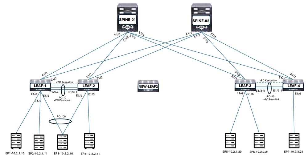
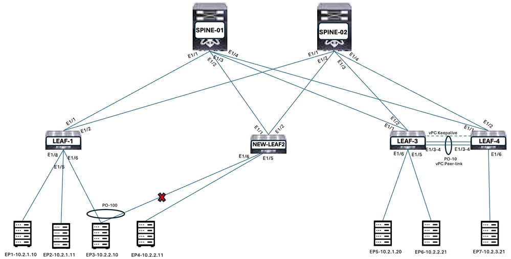
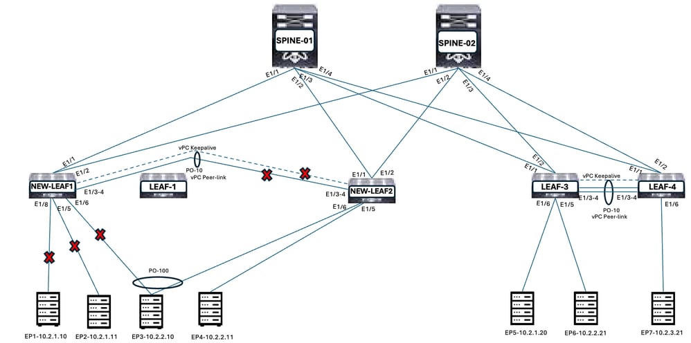
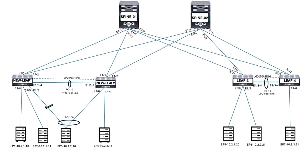
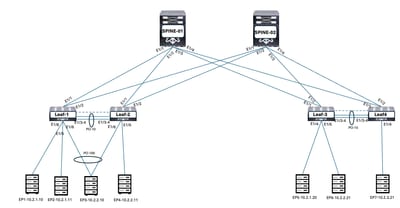
VXLAN Leaf-Spine Architecture
Figure 1. VXLAN Leaf-Spine Topology
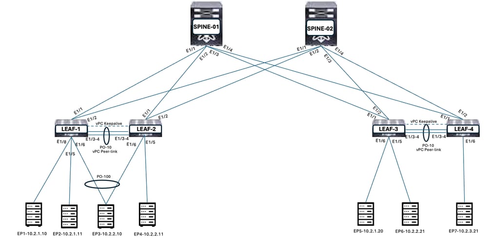
VXLAN Leaf-Spine Architecture Highlights
- LEAF-1 and LEAF-2 are Virtual Port Channel (vPC) peers. LEAF-3 and LEAF-4 are vPC peers.
- Anycast Gateway are configured on LEAF-1, LEAF-2, LEAF-3, and LEAF-4 for VLAN101, VLAN102, and VLAN103.
- Point-to-Point IP addresses configured between Leaf and Spines.
- Loopback0 primary IP Addresses is used for Leaf individual node VXLAN Tunnel Endpoint (vTEP).
- Loopback0 Secondary IP Addresses is shared between vPC Leaf member as anycast vTEP (vip).
- Open Shortest Path First (OSPF) routing protocol is used between Leaf and Spines for Underlay. Loopback0 advertised from Leaf and Spine through OSPF.
- Border Gateway Protocol (BGP) L2VPN is used between Leaf and Spines for Overlay. BGP L2VPN EVPN peering established on Loopback0.
- VLAN101, VLAN102, and VLAN103 subnets are advertised to Leaf and Spines.
Table 1. Leaf Loopback IP Addresses
|
Spine/Leaf Hostname
|
Loopback0 Primary IP
|
Loopback0 Secondary IP (vip)
|
|
SPINE-1
|
10.7.1.1/32
|
|
|
SPINE-2
|
10.7.1.2/32
|
|
|
LEAF-1
|
10.5.1.1/32
|
10.0.1.72/32
|
|
LEAF-2
|
10.5.1.2/32
|
10.0.1.72/32
|
|
LEAF-3
|
10.6.1.1/32
|
10.0.2.72/32
|
|
LEAF-4
|
10.6.1.2/32
|
10.0.2.72/32
|
Routes Verification from Leaf and Spines
Figure 2. Verify routes on Leaf switches.
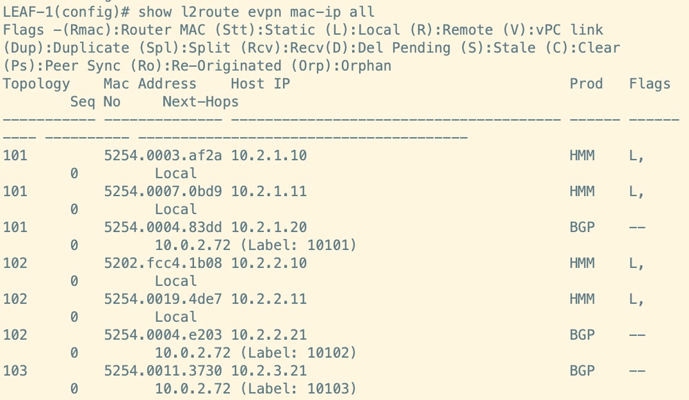
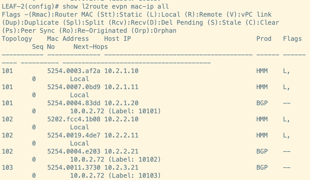

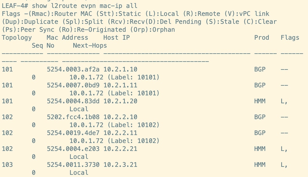
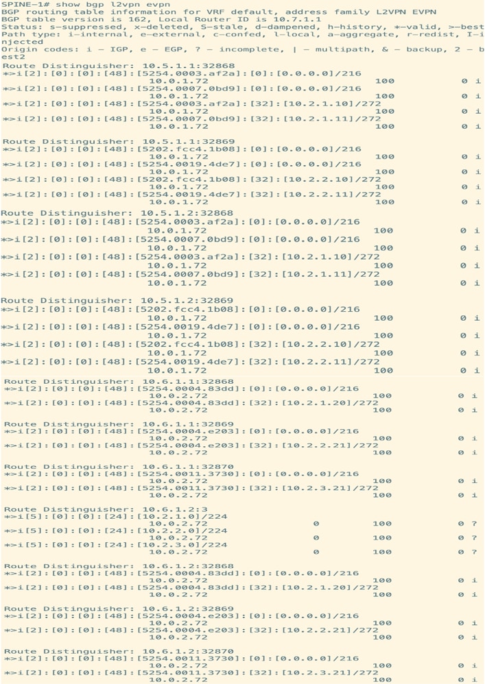
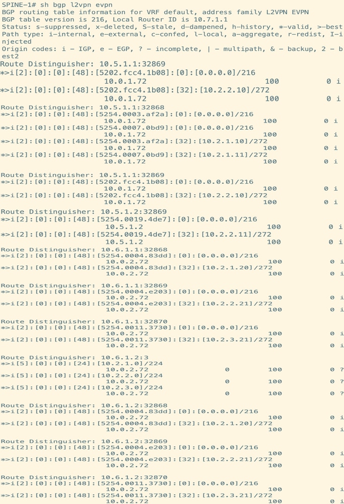
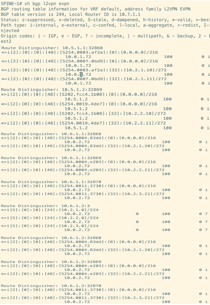
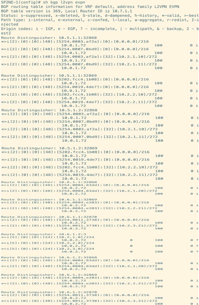
Figure 3. Verify routes on Spine switches (it remains same on both spine switches).
Nexus Switch Hardware Refresh Steps
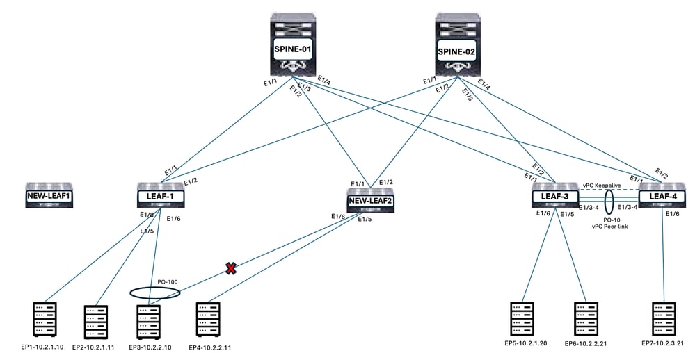
Step 1. Copy Configuration from LEAF-2 to NEW-LEAF2
Copy configuration from LEAF-2 to NEW-LEAF2. Shut down all the interfaces on NEW-LEAF2.
Figure 4. Configure NEW-LEAF2
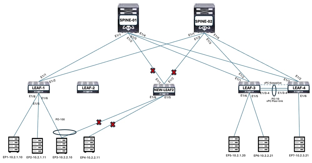
Step 2. Isolate vPC Secondary Switch by Shutting all the Interfaces (LEAF-2 is vPC Secondary Switch)
The sequence to shut down the interfaces on secondary switch:
- Shutdown vPC Member ports and Orphan ports
- Shutdown uplinks towards Spines
- Shutdown vPC keepalive link
- Shutdown vPC Peer link
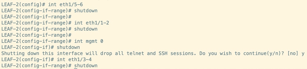
Figure 5. Isolate vPC secondary switch
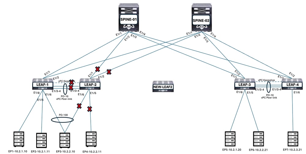
Figure 6. Shut down the interfaces on secondary switch
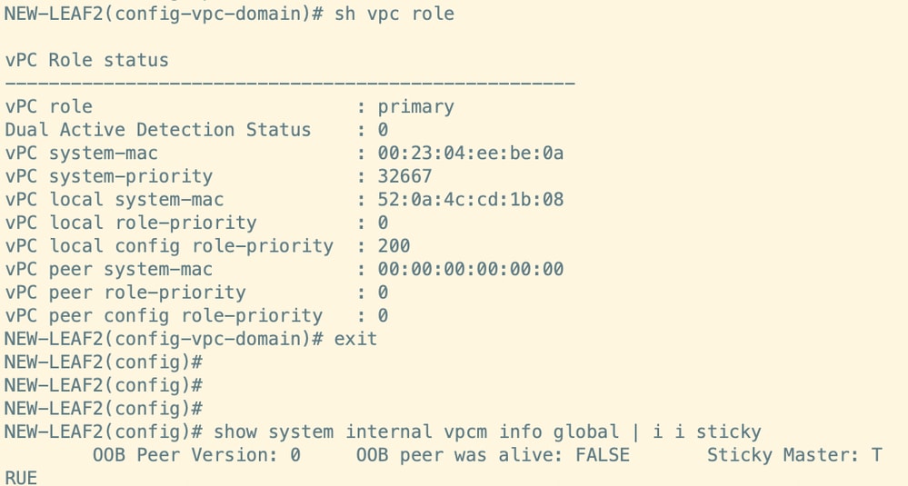
Step 3. Verify the vPC Sticky Bit on NEW-LEAF2
Sticky bit must be 'False'. If it is 'True', increase the vPC priority higher than the previous value. Reload the Leaf in case if sticky bit status did not change to 'False'. NEW-LEAF2 is configured with vPC auto-recovery, hence it is vPC primary switch. It is not forming any vPC peering with LEAF-1, as the Peer-link and Peer-keepalive are down.
Figure 7. NEW-LEAF2 is vPC Primary
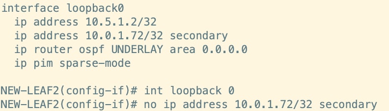
Step 4. Remove Secondary IP Address from Loopback0 from NEW-LEAF2
This step is to ensure that once the links comes up, Routes for Endpoints connected on Orphan ports are sent to the Leaf and Spines from NEW-LEAF2.
Figure 8. Remove secondary IP address from Loopback0
Step 5. Connect the Cables to NEW-LEAF2
Complete the cable connectivity from NEW-LEAF2 to Spines and Endpoints.
Figure 9. Connect the cables to NEW-LEAF2
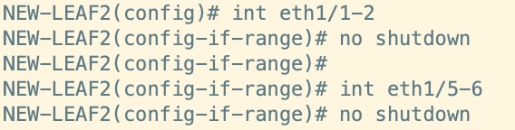
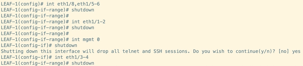
Step 6. Unshut the Uplink Ports and Orphan Ports on NEW-LEAF2
Unshut Uplink ports and Orphan ports on NEW-LEAF2. vPC keepalive, vPC peer link, and vPC members to be kept shut.
This step ensures the routes for Orphan ports are sent to the Spines and other Leaf through NEW-LEAF2. Routes for vPC member ports are sent through the LEAF-1 only.
Figure 10. Unshut the Orphan ports and Uplink ports on NEW-LEAF2
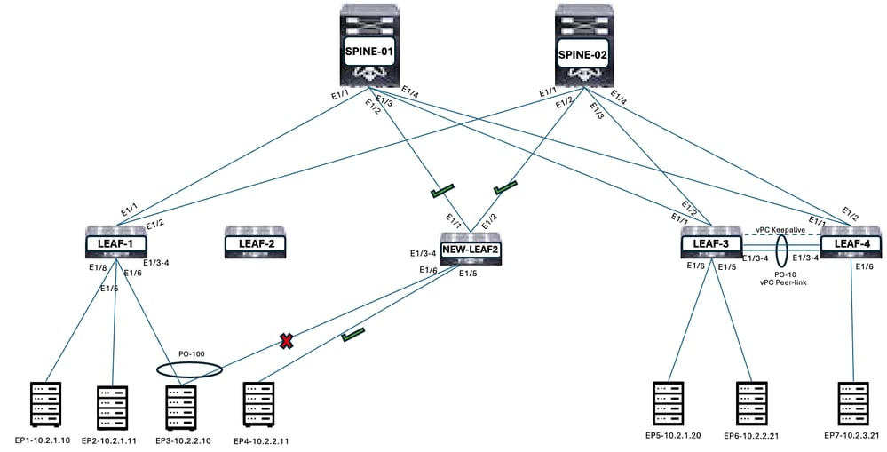
Figure 11. Output for 'unshut the interfaces' on NEW-LEAF2
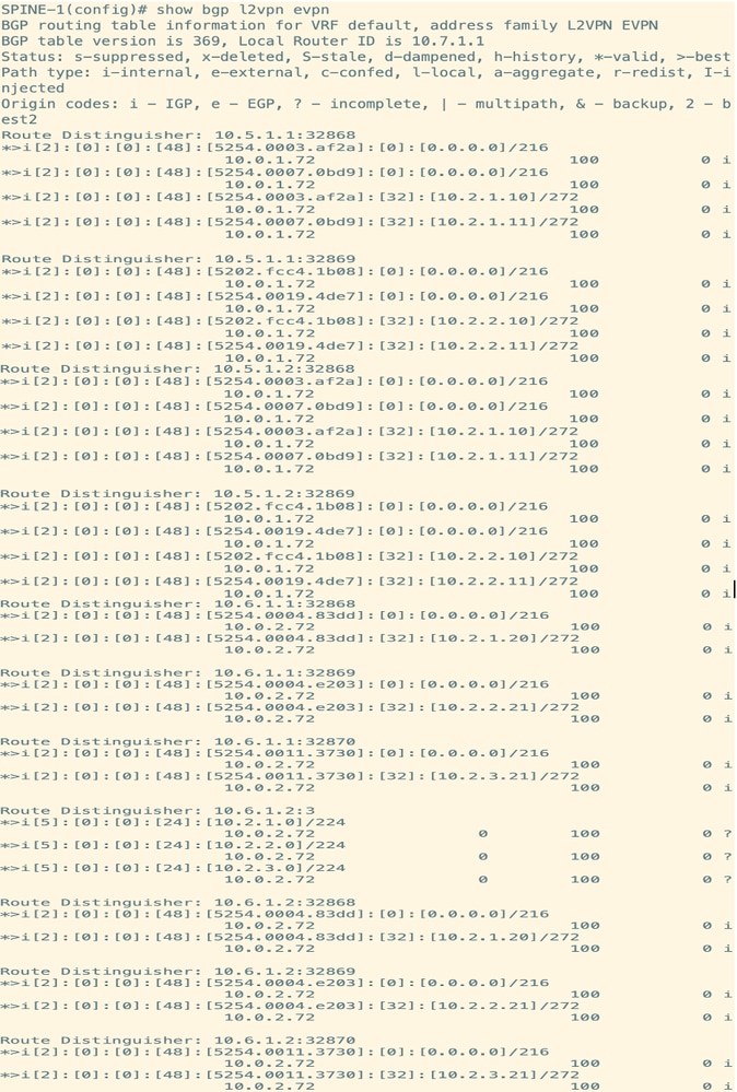
Step 7. Verify the Routes in Spine and Other Leaf which are Received from NEW-LEAF2 for Orphan Ports
NEW-LEAF2 routes for orphan ports are advertised to Spines and other Leaf. NEW-LEAF2 Loopback0 primary IP address is the Next Hop address for the routes.
Figure 12. Verify Routes on Leaf
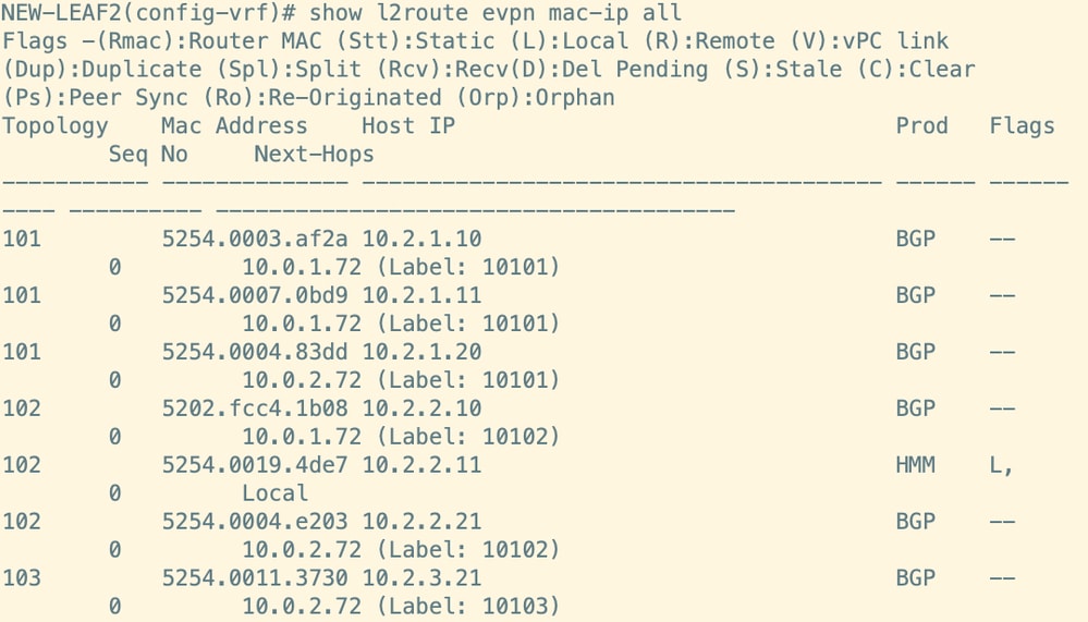
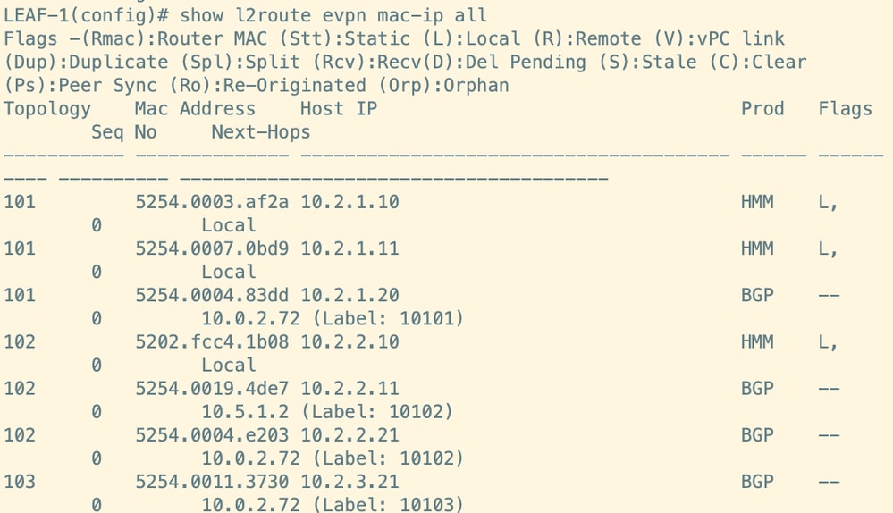
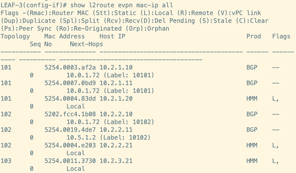

Figure 13. Verify Routes on Spines. It remains same on both spines.
Step 8. vPC between LEAF-1 and NEW-LEAF2 Remains Down
There is no connectivity between Leaf-1 and NEW-LEAF2, hence vPC peering is not formed.
Figure 14. vPC peering between LEAF-1 and NEW-LEAF2 is down
Step 9. Copy Configuration from LEAF-1 to NEW-LEAF1
Copy configuration from LEAF-1 to NEW-LEAF1. Shut down all the interfaces on NEW-LEAF1.
Figure 15. Configure NEW-LEAF1
Step 10. Isolate LEAF-1
The sequence to shut down the interfaces on primary switch:
- Shutdown vPC Member ports and Orphan ports
- Shutdown uplinks towards Spines
- Shutdown vPC peer link and keepalive link
Figure 16. Isolate LEAF-1
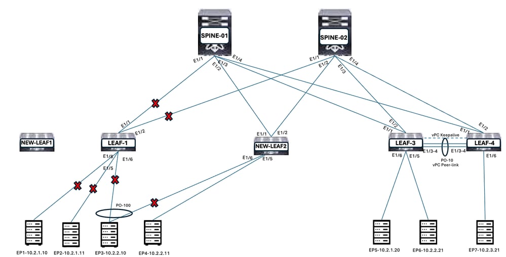
Figure 17. Shut down the interfaces on LEAF-1
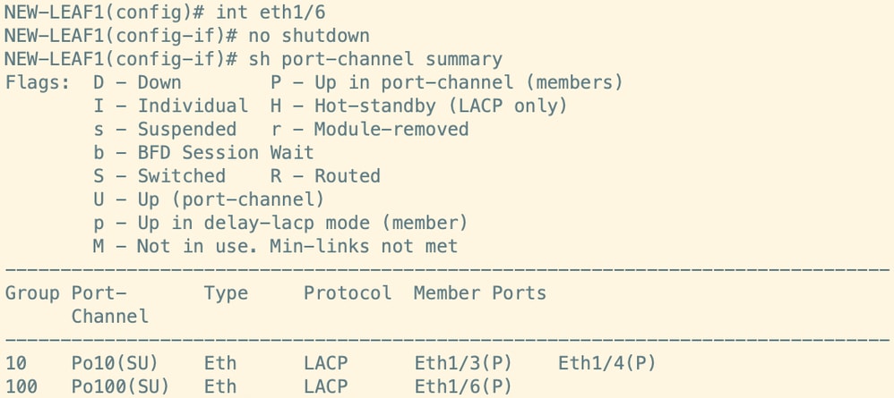
Step 11. Unshut the vPC Member Ports NEW-LEAF2
Unshut vPC member ports NEW-LEAF2.
Figure 18. Unshut the vPC member ports on NEW-LEAF2
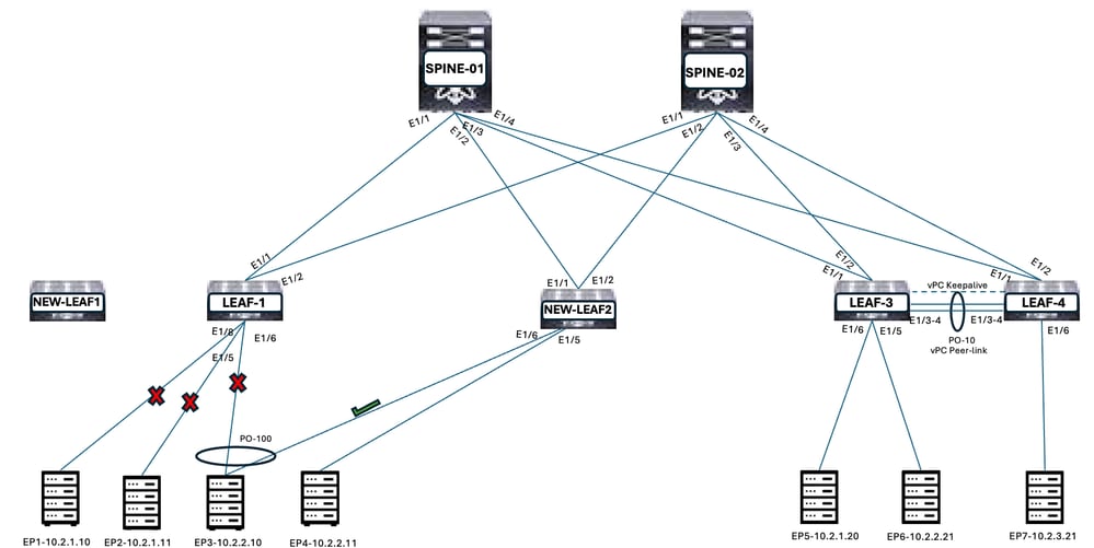
Figure 19. Output for unshut the interfaces on NEW-LEAF2

Step 12. Verify the Routes in Spine and Other Leaf which are Received from NEW-LEAF2
NEW-LEAF2 routes for vPC member ports are advertised to Spines and other Leaf. NEW-LEAF2 Loopback0 primary IP address is the Next Hop address for the routes.
Figure 20. Verify Routes on Leaf
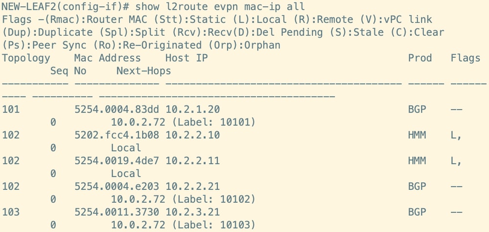
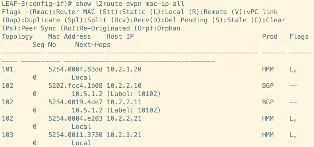
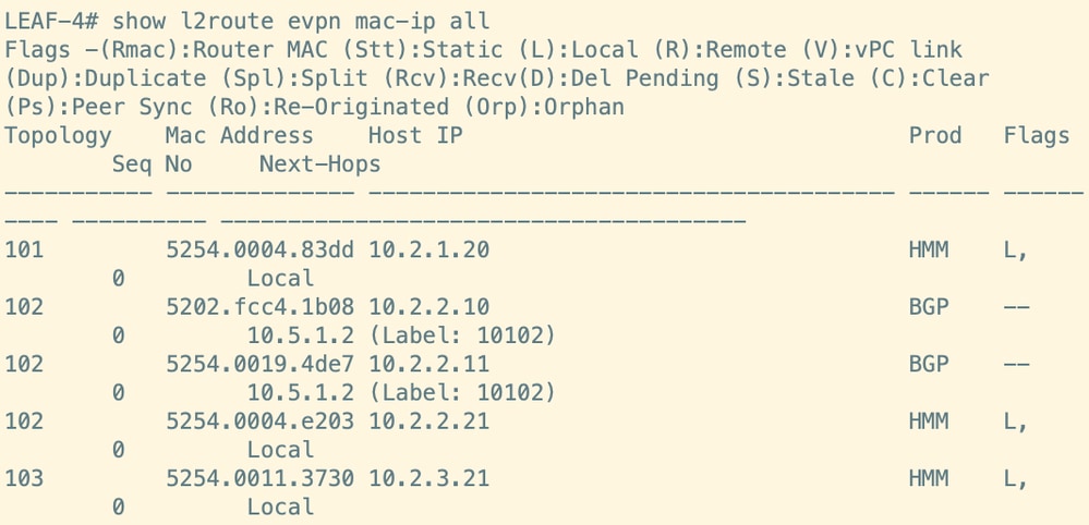
Figure 21. Verify Routes on Spines. It remains same on both spines.
Step 13. Connect the Cables to NEW-LEAF1 (Keep the Interfaces Shut)
Figure 22. Connect the cables to NEW-LEAF1
Step 14. Unshut the Uplink Ports and Orphan Ports on NEW-LEAF1
Unshut Uplinks ports and Orphan ports on NEW-LEAF1. vPC keepalive, vPC peer link and vPC members must be kept shut.
This step ensures the routes for Orphan ports are sent to the Spines and other Leaf through NEW-LEAF1. Routes for vPC member ports are sent through the NEW-LEAF2 only.
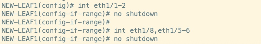
Figure 23. Unshut the Uplink ports and Orphan ports on NEW-LEAF1
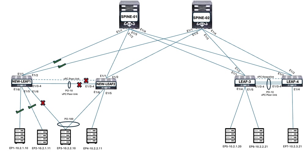
Figure 24. Output for unshut the interfaces on NEW-LEAF1
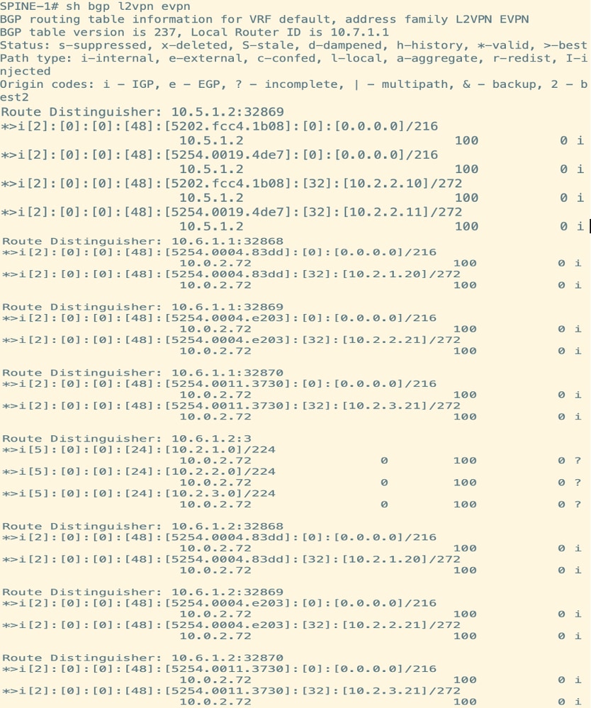
Step 15. Verify the Routes in Spine and Other Leaf which are Received from NEW-LEAF1 for Orphan Ports
NEW-LEAF1 routes for orphan ports are advertised to Spines and other Leaf. NEW-LEAF1 Loopback0 secondary IP address is the Next Hop address for the routes.
Figure 25. Verify Routes on Leaf
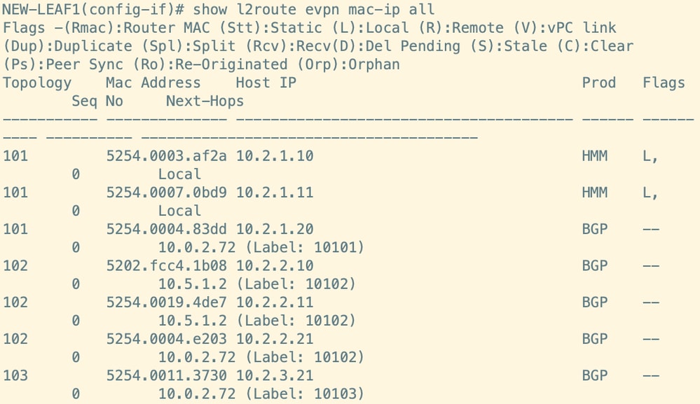
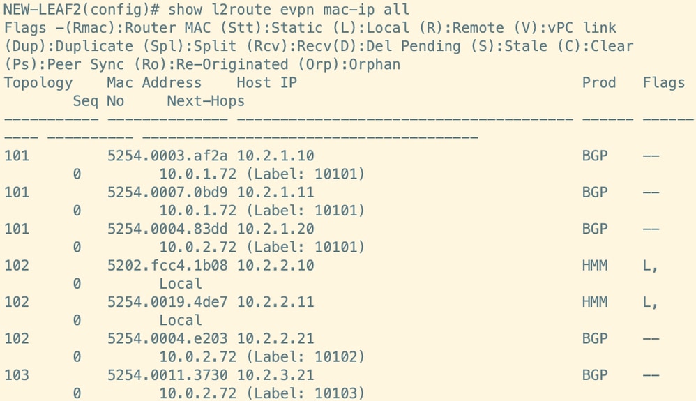
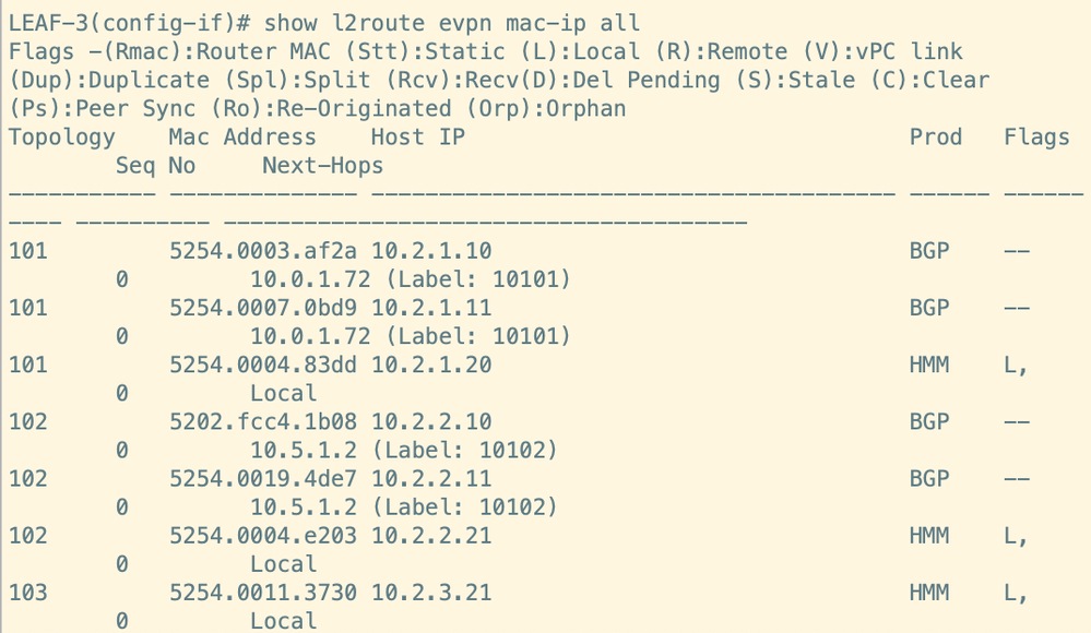
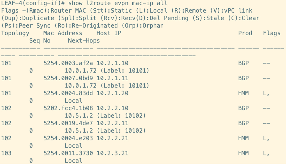
Figure 26. Verify Routes on Spines. It remains same on both spines.
Step 16. Bring up the vPC Between NEW-LEAF1 and NEW-LEAF2
Unshut vPC Peer-link and vPC keepalive link between NEW-LEAF1 and NEW-LEAF2. Verify the vPC status. vPC primary and secondary switch elected on the basis of vPC role priority.
Figure 27. Bring up the vPC between NEW-LEAF1 and NEW-LEAF2
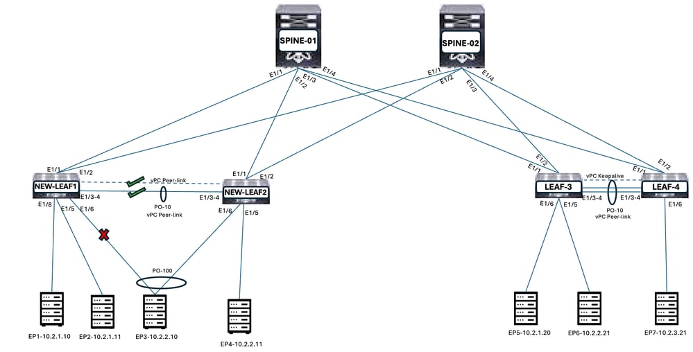
Figure 28. Output for unshut the vPC Peer-link and vPC keepalive on NEW-LEAF1 and NEW-LEAF2
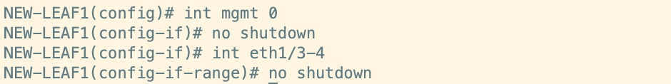
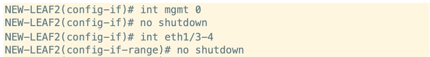
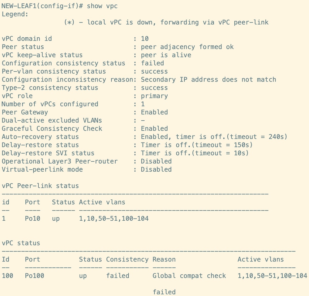
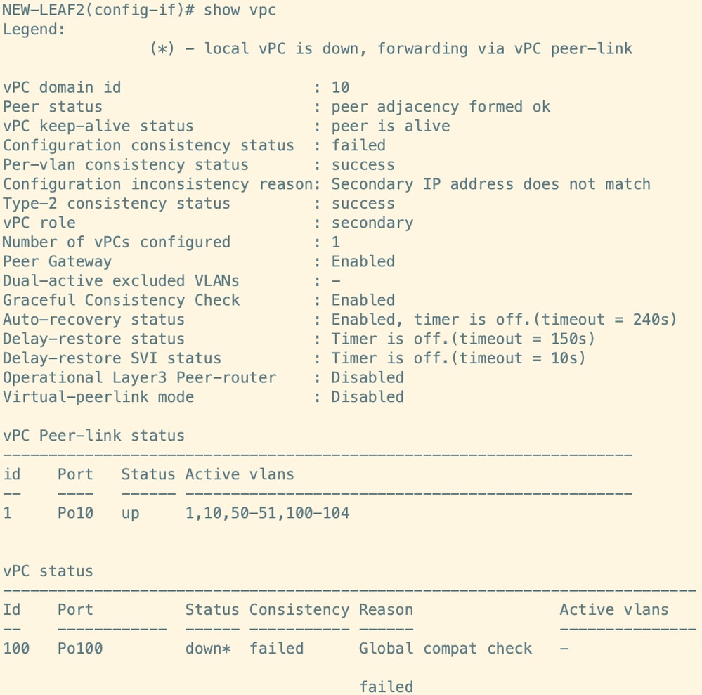
Figure 29. Output for vPC status
There is vPC inconsistency due to Secondary IP address does not match on Loopback0. This causes the downtime for vPC member ports.
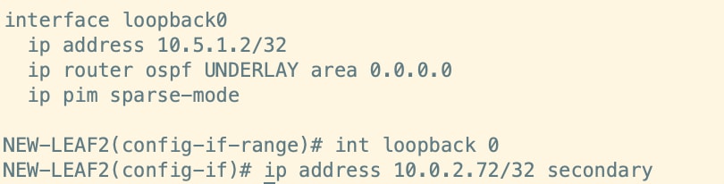
Step 17. Add the Secondary IP Address in Loopback0 on NEW-LEAF2
Reconfigure Loopback0 Secondary IP Address on NEW-LEAF-2.
Figure 30. Add Secondary IP address in Loopback0 on NEW-LEAF-2
Step 18. Verify the Routes in Spine and Other Leaf which are Received from NEW-LEAF1 and NEW-LEAF2 for all the Endpoints
NEW-LEAF1 and NEW-LEAF2 routes for all the endpoints are advertised to Spines and other Leaf. Next Hop is Loopback0 secondary IP.
Figure 31. Output for vPC status
There is vPC inconsistency is resolved after adding Loopback0 secondary IP address. This step has to be done after vPC peering formed. This reduces the downtime for Endpoints.
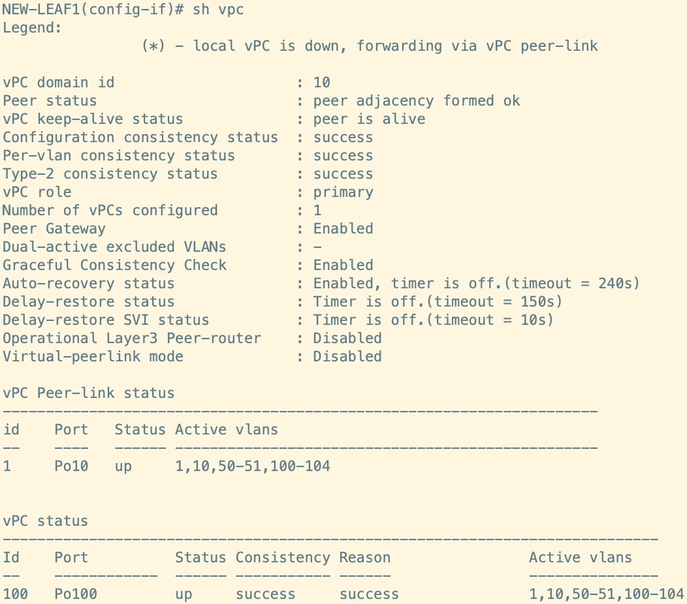
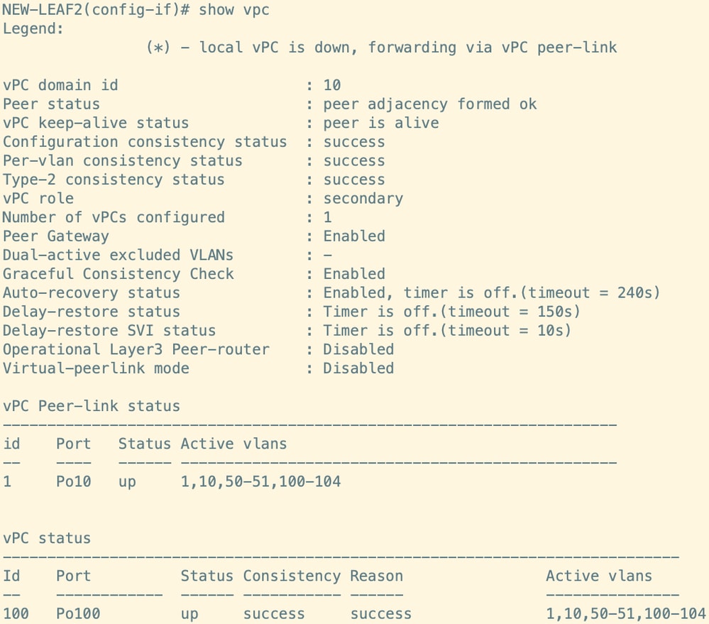
Figure 32. Verify Routes on Leaf
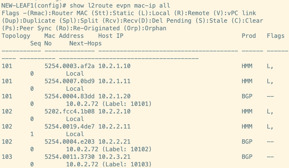
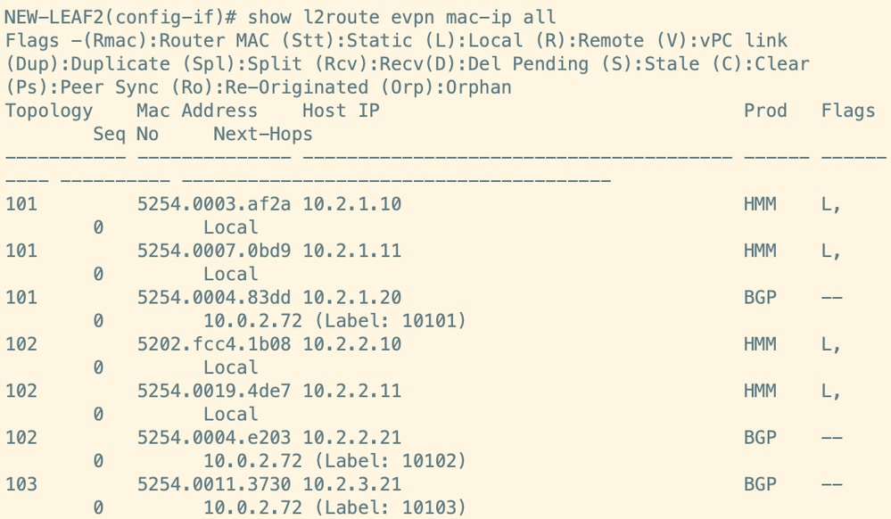
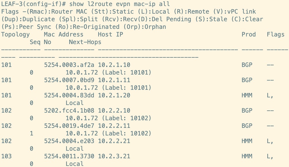

Figure 33. Verify Routes on Spines. It remains same on both spines.
Step 19. Unshut the vPC Member Ports on NEW-LEAF1
Unshut vPC member ports on NEW-LEAF1.
Figure 34. Unshut the vPC member ports on NEW-LEAF1
Step 20. Unshut the vPC Member Ports NEW-LEAF1
Unshut vPC member ports NEW-LEAF1.
Figure 35. Unshut the vPC member ports on NEW-LEAF1
Step 21. Verify the Routes in Spine and Other Leaf which are Received from NEW-LEAF1 and NEW-LEAF2
NEW-LEAF1 and NEW-LEAF2 routes for all the endpoints are advertised to Spines and other Leaf. Next Hop is Loopback0 secondary IP.
Figure 36. Verify Routes on Leaf

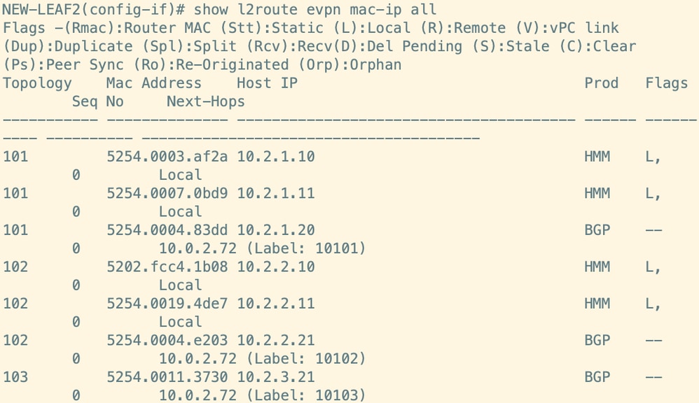
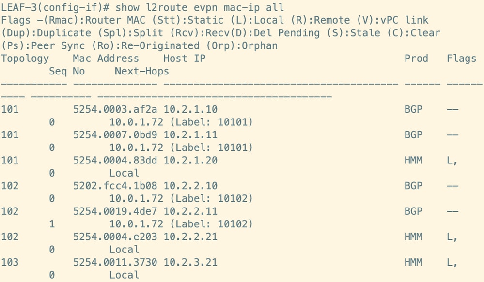
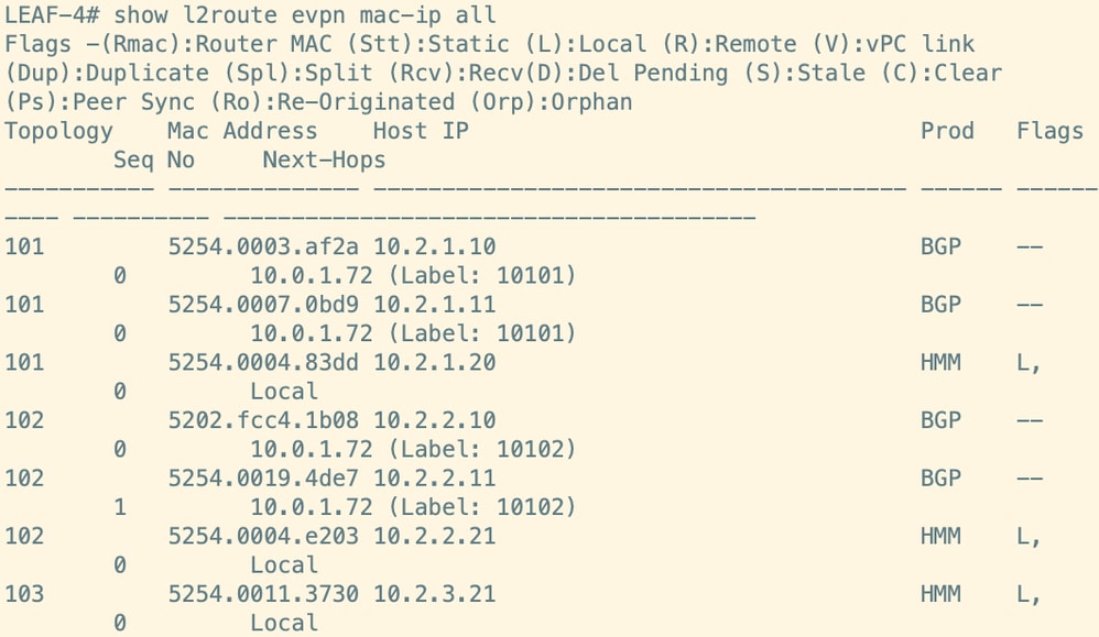
Figure 37. Verify Routes on Spines. It remains same on both spines.
 Feedback