Verify Packets Using PHY and HW QoS Counters
Available Languages
Download Options
Bias-Free Language
The documentation set for this product strives to use bias-free language. For the purposes of this documentation set, bias-free is defined as language that does not imply discrimination based on age, disability, gender, racial identity, ethnic identity, sexual orientation, socioeconomic status, and intersectionality. Exceptions may be present in the documentation due to language that is hardcoded in the user interfaces of the product software, language used based on RFP documentation, or language that is used by a referenced third-party product. Learn more about how Cisco is using Inclusive Language.
Contents
Introduction
This document describes how PHY counters help verify packet arrival using frame size rather than detailed traffic analysis.
Prerequisites
Requirements
There are no specific requirements for this document.
Components Used
The information in this document is based on these software and hardware versions.
- C9300
- Cisco IOS® XE 17.9.5
- Cisco IOS® XE 17.15.3
This document provides information on the use of PHY controller counters as the first inspection point for incoming packets on a switch. These counters provide visibility into whether packets arrive based on frame size rather than detailed traffic flow analysis.
The information in this document was created from the devices in a specific lab environment. All of the devices used in this document started with a cleared (default) configuration. If your network is live, ensure that you understand the potential impact of any command.
Related Products
This document can also be used with these hardware versions:
- C9200
- C9300
- C9400
- C9500
- C9600

Caution: DSCP counters are not supported as part of troubleshooting tests on Silicon One–based platforms such as Catalyst 9600X (Sup-2 & Sup-3), 9500X, and 9350.
PHY Controller Counters Background
The PHY controller is the first component a packet encounters when it enters a switch. It operates at Layer 1 and provides visibility into whether packets are physically received or transmitted on an interface. Unlike higher-layer counters such as MAC or IP statistics, PHY counters rely on frame size and byte counts to confirm packet arrival or transmission.
This makes them a valuable diagnostic tool to validate physical-layer traffic behavior and detect potential ingress or egress issues before packets reach higher processing layers.
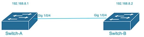
Network Diagram
PHY Controller Counters Output
The example from a Cisco Catalyst switch shows statistics collected at the PHY controller level:
Switch-A#show controllers ethernet-controller GigabitEthernet 1/0/4
Transmit                  GigabitEthernet1/0/4          Receive
         1906 Total bytes                          64 Total bytes
            1 Unicast frames                        1 Unicast frames
           64 Unicast bytes                        64 Unicast bytes
            8 Multicast frames                      0 Multicast frames
         1842 Multicast bytes                       0 Multicast bytes
            0 Broadcast frames                      0 Broadcast frames
            0 Broadcast bytes                       0 Broadcast bytes
            0 System FCS error frames               0 IpgViolation frames
            0 MacUnderrun frames                    0 MacOverrun frames
            0 Pause frames                          0 Pause frames
            0 Cos 0 Pause frames                    0 Cos 0 Pause frames
            0 Cos 1 Pause frames                    0 Cos 1 Pause frames
            0 Cos 2 Pause frames                    0 Cos 2 Pause frames
            0 Cos 3 Pause frames                    0 Cos 3 Pause frames
            0 Cos 4 Pause frames                    0 Cos 4 Pause frames
            0 Cos 5 Pause frames                    0 Cos 5 Pause frames
            0 Cos 6 Pause frames                    0 Cos 6 Pause frames
            0 Cos 7 Pause frames                    0 Cos 7 Pause frames
            0 Oam frames                            0 OamProcessed frames
            0 Oam frames                            0 OamDropped frames
            5 Minimum size frames                   1 Minimum size frames
            0 65 to 127 byte frames                 0 65 to 127 byte frames
            0 128 to 255 byte frames                0 128 to 255 byte frames
            4 256 to 511 byte frames                0 256 to 511 byte frames
            0 512 to 1023 byte frames               0 512 to 1023 byte frames
            0 1024 to 1518 byte frames              0 1024 to 1518 byte frames
            0 1519 to 2047 byte frames              0 1519 to 2047 byte frames
            0 2048 to 4095 byte frames              0 2048 to 4095 byte frames
            0 4096 to 8191 byte frames              0 4096 to 8191 byte frames
            0 8192 to 16383 byte frames             0 8192 to 16383 byte frames
            0 16384 to 32767 byte frame             0 16384 to 32767 byte frame
            0 > 32768 byte frames                   0 > 32768 byte frames
            0 Late collision frames                 0 SymbolErr frames
            0 Excess Defer frames                   0 Collision fragments
            0 Good (1 coll) frames                  0 ValidUnderSize frames
            0 Good (>1 coll) frames                 0 InvalidOverSize frames
            0 Deferred frames                       0 ValidOverSize frames
            0 Gold frames dropped                   0 FcsErr frames
            0 Gold frames truncated
            0 Gold frames successful
            0 1 collision frames
            0 2 collision frames
            0 3 collision frames
            0 4 collision frames
            0 5 collision frames
            0 6 collision frames
            0 7 collision frames
            0 8 collision frames
            0 9 collision frames
            0 10 collision frames
            0 11 collision frames
            0 12 collision frames
            0 13 collision frames
            0 14 collision frames
            0 15 collision frames
            0 Excess collision frames

LAST UPDATE 346 msecs AGO
Switch-A#show controllers ethernet-controller Gig 1/0/4
Transmit GigabitEthernet1/0/4 Receive
3169535406 Total bytes 307126227 Total bytes
290349 Unicast frames 294295 Unicast frames
18660704 Unicast bytes 18929926 Unicast bytes
33923210 Multicast frames 3074668 Multicast frames
3150872686 Multicast bytes 251494767 Multicast bytes
30 Broadcast frames 141745 Broadcast frames
2016 Broadcast bytes 36701534 Broadcast bytes
0 System FCS error frames 0 IpgViolation frames
0 MacUnderrun frames 0 MacOverrun frames
0 Pause frames 0 Pause frames
0 Cos 0 Pause frames 0 Cos 0 Pause frames
0 Cos 1 Pause frames 0 Cos 1 Pause frames
0 Cos 2 Pause frames 0 Cos 2 Pause frames
0 Cos 3 Pause frames 0 Cos 3 Pause frames
0 Cos 4 Pause frames 0 Cos 4 Pause frames
0 Cos 5 Pause frames 0 Cos 5 Pause frames
0 Cos 6 Pause frames 0 Cos 6 Pause frames
0 Cos 7 Pause frames 0 Cos 7 Pause frames
0 Oam frames 0 OamProcessed frames
0 Oam frames 0 OamDropped frames
1221612 Minimum size frames 847707 Minimum size frames
31115917 65 to 127 byte frames 2403801 65 to 127 byte frames
69441 128 to 255 byte frames 135289 128 to 255 byte frames
1227890 256 to 511 byte frames 112047 256 to 511 byte frames
578669 512 to 1023 byte frames 11824 512 to 1023 byte frames
40 1024 to 1518 byte frames 40 1024 to 1518 byte frames
20 1519 to 2047 byte frames 0 1519 to 2047 byte frames
0 2048 to 4095 byte frames 0 2048 to 4095 byte frames
0 4096 to 8191 byte frames 0 4096 to 8191 byte frames
0 8192 to 16383 byte frames 0 8192 to 16383 byte frames
0 16384 to 32767 byte frame 0 16384 to 32767 byte frame
0 > 32768 byte frames 0 > 32768 byte frames
0 Late collision frames 0 SymbolErr frames
0 Excess Defer frames 0 Collision fragments
0 Good (1 coll) frames 0 ValidUnderSize frames
0 Good (>1 coll) frames 0 InvalidOverSize frames
0 Deferred frames 0 ValidOverSize frames
0 Gold frames dropped 0 FcsErr frames
0 Gold frames truncated
0 Gold frames successful
0 1 collision frames
0 2 collision frames
0 3 collision frames
0 4 collision frames
0 5 collision frames
0 6 collision frames
0 7 collision frames
0 8 collision frames
0 9 collision frames
0 10 collision frames
0 11 collision frames
0 12 collision frames
0 13 collision frames
0 14 collision frames
0 15 collision frames
0 Excess collision frames
LAST UPDATE 3227 msecs AGO
Switch-A#Key Points from the Output
- Total bytes and frames show the overall traffic count, separated into transmit and receive directions.
- Unicast, multicast, and broadcast frames display the distribution of traffic types.
- Frame size ranges indicate how many packets of a given size are received or transmitted (for example, minimum-size frames, 65–127 bytes, 256–511 bytes).
- Error counters indicate Layer 1 issues such as FCS errors, collisions, underruns, overruns, or symbol errors.
- The last update field shows the time elapsed since the PHY statistics are last updated.
Ping Using PHY Controller Counters
A common use case for PHY controller counters is validating whether test traffic transmits or receives on an interface. By sending a controlled traffic stream, such as ICMP packets of a specific size, and monitoring the counters, engineers confirm whether the traffic reaches the PHY layer.r.
Example: Using ICMP with a Specific Packet Size
Initially, the PHY counters for the interface show no activity in the 1024–1518 byte range.
Switch-A#show controllers ethernet-controller GigabitEthernet 1/0/4
Transmit                  GigabitEthernet1/0/4          Receive

            5 Minimum size frames                   1 Minimum size frames
            0 65 to 127 byte frames                 0 65 to 127 byte frames
            0 128 to 255 byte frames                0 128 to 255 byte frames
            4 256 to 511 byte frames                0 256 to 511 byte frames
            0 512 to 1023 byte frames               0 512 to 1023 byte frames
            0 1024 to 1518 byte frames<<<<<         0 1024 to 1518 byte frames <<<<<
            0 1519 to 2047 byte frames              0 1519 to 2047 byte frames
            0 2048 to 4095 byte frames              0 2048 to 4095 byte frames
            0 4096 to 8191 byte frames              0 4096 to 8191 byte frames
            0 8192 to 16383 byte frames             0 8192 to 16383 byte frames
            0 16384 to 32767 byte frame             0 16384 to 32767 byte frame
            0 > 32768 byte frames                   0 > 32768 byte frames
A ping test executes using 1,000 ICMP packets with a size of 1,200 bytes, which increments the 1024–1518 byte frame counters.
Switch-A#ping 192.168.8.2 repeat 1000 timeout 0 size 1200
Type escape sequence to abort.
Sending 1000, 1200-byte ICMP Echos to 192.168.8.2, timeout is 0 seconds:
......................................................................
......................................................................
Success rate is 0 percent (0/1000), round-trip min/avg/max = 1/1/1 ms
Switch-A#
After the test, the transmit counters show the packets sent, confirming that they leave the interface, even if no replies are received.
Switch-A#show  controllers ethernet-controller GigabitEthernet 1/0/4
Transmit                  GigabitEthernet1/0/4          Receive

            7 Minimum size frames                   6 Minimum size frames
            0 65 to 127 byte frames                 0 65 to 127 byte frames
            0 128 to 255 byte frames                0 128 to 255 byte frames
           28 256 to 511 byte frames                2 256 to 511 byte frames
            0 512 to 1023 byte frames               0 512 to 1023 byte frames
         1000 1024 to 1518 byte frames <<<<<     1000 1024 to 1518 byte frames <<<<<
            0 1519 to 2047 byte frames              0 1519 to 2047 byte frames
            0 2048 to 4095 byte frames              0 2048 to 4095 byte frames
            0 4096 to 8191 byte frames              0 4096 to 8191 byte frames
            0 8192 to 16383 byte frames             0 8192 to 16383 byte frames
            0 16384 to 32767 byte frame             0 16384 to 32767 byte frame
            0 > 32768 byte frames                   0 > 32768 byte frames
Even though the ping test shows 0% success, the PHY controller counters confirm that 1,000 packets of 1,200 bytes transmit successfully. This demonstrates how PHY counters validate traffic generation and transmission independently of higher-layer responses.

Tip: Run multiple iterations for consistency, or clear counters beforehand with: clear controller ethernet-controller <interface>.

Note: This testing approach is viable on interfaces configured as Layer 3 routed ports (no switchport), access mode ports, trunk ports, and EtherChannel members. For EtherChannel configurations, counters must be validated on the individual physical interfaces that are part of the channel group.
HW QoS DSCP Counters
HW QoS counters are highly reliable and operate just PHY controller counters in the hardware pipeline, likely at the ingress and egress FIFO level. These counters help validate whether packets with specific Differentiated Services Code Point (DSCP) markings reach or leave an interface.
Compared to PHY controller counters, HW QoS counters are easier to use because they offer granularity across 64 DSCP values. This allows engineers to verify traffic presence based on QoS classification rather than relying only on frame size.
HW QoS DSCP Output
Switch-A#show platform hardware fed switch active qos dscp-cos counters interface GigabitEthernet 1/0/4


Frames        Bytes
Ingress DSCP0 374959        0
Ingress DSCP1 0             0
Ingress DSCP2 0             0
Ingress DSCP3 0             0
Ingress DSCP4 0             0
...

Switch-A#
Key Points
-
Reliability: HW QoS counters are highly trustworthy, slightly less fundamental than PHY controller counters.
-
Granularity: Support for 64 DSCP values enables precise traffic classification.
-
Requirement: Controlled test traffic with consistent DSCP marking is necessary for accurate validation.
-
Limitation: HW QoS counters do not differentiate between multiple flows sharing the same DSCP value.
Note: Please refer to the network diagram provided at the beginning of this document for reference.
Ping Using HW QoS DSCP Counters
Example: Using ICMP with DSCP Marking
HW QoS DSCP counters can be effectively leveraged to validate whether traffic with a specific DSCP marking is arriving at or leaving an interface. This capability is particularly useful in scenarios involving controlled test traffic, where a unique DSCP value is applied to easily track the presence of packets in hardware counters. By using these counters, engineers can confirm traffic flow based on QoS classification at the hardware level, independent of higher-layer protocols. This method provides granular visibility since HW QoS counters support tracking across 64 possible DSCP values, enabling precise classification and validation of traffic presence on interfaces
Initially, the counters show no traffic for DSCP values 1 and 2:
Switch-A# show platform hardware fed switch 1 qos dscp-cos counters interface GigabitEthernet 1/0/4

Ingress DSCP0 374959        0
Ingress DSCP1 0             0 <<<<
Ingress DSCP2 0             0 <<<<
A ping test is then run with DSCP 2 marking:
Switch-B# ping 192.168.8.1 repeat 1000 timeout 0 dscp 2
Type escape sequence to abort.
Sending 1000, 100-byte ICMP Echos to 192.168.8.1, timeout is 0 seconds:
......................................................................
......................................................................
Success rate is 0 percent (0/1000)
After the test, the counter for DSCP 2 has incremented by 1000, confirming packet arrival at the ingress interface even though no replies were received:
Switch-A# show platform hardware fed switch 1 qos dscp-cos counters interface GigabitEthernet 1/0/4
Ingress DSCP0 374959        0
Ingress DSCP1 0             0
Ingress DSCP2 1000          0 <<<<
DSCP counters provide an effective method to confirm traffic presence at the hardware level. By marking test traffic with a DSCP value that is otherwise unused, engineers can isolate and validate packet forwarding independently of higher-layer responses. This approach allows for precise tracking of packets in hardware counters, ensuring that traffic with specific DSCP markings is indeed being forwarded through the network. Using unique DSCP values in controlled test traffic helps in isolating and verifying packet flows, which is valuable for troubleshooting and QoS policy validation in Cisco devices.
Tip: Run multiple iterations, or clear DSCP counters first with: clear platform hardware fed switch active qos dscp-cos counters interface <interface>.
Revision History
| Revision | Publish Date | Comments |
|---|---|---|
1.0 |
07-Oct-2025
|
Initial Release |
Contributed by Cisco Engineers
- Ricardo CaballeroTechnical Consulting Engineer
 Feedback
Contact Cisco
- Open a Support Case

- (Requires a Cisco Service Contract)