Introduction
This document describes how to configure and validate Resilient Ethernet Protocol (REP) on Catalyst 9000 switches.
Prerequisites
Requirements
Cisco recommends you have knowledge of these topics:
Components Used
The information in this document is based on these software and hardware versions:
- Catalyst 9200
- Catalyst 9300
- Catalyst 9400
- Catalyst 9500
- Catalyst 9600
- Cisco IOS XE 17.6.5 and later

Caution: REP is not supported on switches with Stackwise Virtual (SVL).
The information in this document was created from the devices in a specific lab environment. All of the devices used in this document started with a cleared (default) configuration. If your network is live, ensure that you understand the potential impact of any command.
Background Information
REP is a Cisco proprietary protocol designed to prevent network loops and provide fast convergence on link failure in layer 2 Ethernet networks. It is an alternative to Spanning Tree Protocol and is often used in specific layer 2 topologies that require large layer 2 extensions such as IoT networks, industrial networks, or manufacturing networks. REP segments are formed by chaining together ports between switches that are configured with the same segment ID. With features like REP Load Balancing and its ability to co-exist with STP, REP can used to construct complex yet predictable layer 2 topologies.
Terminology
|
Term
|
Definition
|
|
Segment
|
Chain of ports connected together that share the same segment ID
|
|
Segment ID
|
Number used to represent the segment and is between 1 and 1024
|
|
REP Port
|
Port that is configured to run REP. STP is disabled on REP ports.
|
|
Edge Port
|
Port that terminates one edge of the REP segment.
|
|
Alternate Port
|
Port that blocks VLANs in the segment to prevent loops. There are 2 alternate ports in the segment if load balancing is configured
|
|
Open Port
|
Port in the segment that is forwarding all VLANs
|
|
Closed Segment
|
REP Segment where both edge ports are on the same switch and have connectivity to one another. Also called a 'Ring Segment'.
|
|
Open Segment
|
REP Segment where edge ports have no connectivity to one another. The edge ports are on different switches and have a blocking port between them.
|
|
Link Status Layer (LSL)
|
3-way handshake protocol responsible for neighbor adjacency establishment and maintaining link status. LSL frames are sent every 1 second on REP ports.
|
|
Hardware Flood Layer (HFL)
|
Layer responsible for facilitating rapid convergence after link failure by flooding REP PDUs via multicast
|
|
Blocked Port Advertisement (BPA)
|
Message sent by a port to advertise the list of VLANs it blocks. BPAs can carry topology changes as well, making the receiving ports flush their MAC table
|
|
End Port Advertisement (EPA)
|
Carries global information about the REP segment and is sent by Edge ports
|
|
REP Admin VLAN
|
VLAN used for flooding REP fast notifications for convergence after link failure. The HFL operates here if it is configured. If not, the REP Admin VLAN is 1.
|
REP Theory
REP is able to prevent switching loops by blocking VLANs on a single port in the segment known as the Alternate port. When all ports in the REP segment are in an UP state, the alternate port is blocking to prevent the loop. When a link in the REP segment fails, or if a switch has a problem resulting in link loss of REP protocol packets, the alternate port beings forwarding for the VLANs it was previously blocking. It is important to note that because of this, REP segments can only handle a single failed port within the segment. More than 1 link failure on the REP segment can result in traffic loss.
When REP is enabled on an interface it immediately blocks all VLANs. The REP LSL takes over and begins sending LSL PDUs to establish an adjacency. The adjacency is created using a 3-way handshake with subsequent LSL hello packets being sent at 1 second intervals to maintain REP neighbors.
During REP neighbor discovery the devices exchange their REP segment ID and their port ID.
- Segment ID is a number between 1 and 1024 and is configured on the interface when enabling REP. This uniquely identifies the REP segment.
- Port ID is a 60-bit word automatically generated from the system MAC address and the port number on the switch.
- The LSL PDU is sent to destination MAC address is 0180.c200.0000
9200-STACK-1#show interface port-channel1 rep detail | i PortID
PortID: 08E978BC1A4FDD80                                         <--- Port ID with system MAC in bold

9200-STACK-1#show version | i MAC
Base Ethernet MAC Address : 78:bc:1a:4f:dd:80                    <-- Switch system MAC
A REP port moves to into a Failed status after it is shut down or the LSL hello timeout expires after 5 seconds.
REP Alternate Port Election
The REP Alternate port is the port in the segment that is blocking VLANs.
- The election of the Alternate port happens immediately after REP neighbors are established using a proposal and agreement mechanism to determine which single port in the segment remains blocking.
- Every port in the segment advertises its port key and port priority and waits for the agreement.
- The port that has the highest priority gets elected as the Alternate port.
- The election process occurs via REP BPA messages.
Blocked Port Advertisements
A BPA message consists of a Port Key and Port Priority.
- The REP Port Key is a 9-byte identifier that is generated every time the port goes into a blocking state, which is immediately on link-up for REP enabled ports.
- It is a combination of the port ID and a randomly generated number.
- The Port Priority is also a 9-byte identifier.
Alternate Port Election
- On link-up and while the REP port is in a blocking state, it advertises its port key and priority to its REP neighbor
- The receiving port compares the received BPA port priority with its own port priority
- The receiving port responds with an ACK message containing the key that was received in the BPA from the neighbor port. When the neighbor receives its own key in the BPA it knows the BPA is an ACK message from its neighbor
- If the ACK contains a port priority that is higher than the local port priority, the local port moves to an OPEN status. It does not respond to the neighbor with the higher priority but it does forward the proposal out its other REP port to its other REP neighbor
- The other REP neighbor compares the received port priority to its own. If the received priority is higher than the local priority, it also does not respond and forwards the proposal along. If the local priority is higher it responds to the original proposal with its own priority
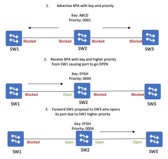
This process repeats until the highest priority port stays in blocking mode. This becomes the segment Alternate port. The Alternate port continues to send BPA messages containing its port key to the REP segment. All REP ports in the segment cache the key of the Alternate port.
In a stable REP segment all ports are in agreement on the Alternate port by all having the same copy of the alternate port key. Every switch maintaining the port key ID of the Alternate port becomes relevant during link failure scenarios.
End Port Advertisements
EPA messages are generated by edge ports every 4 seconds. These messages are forwarded by every REP interface in the segment and each port adds its own topology information to the message. Once the edge port receives an EPA generated by the other edge port in the segment it has a full topology of the entire segment.
EPAs allow each edge port to see each other and facilitates the election of the primary edge port. The edge port with the highest priority becomes the primary edge port.
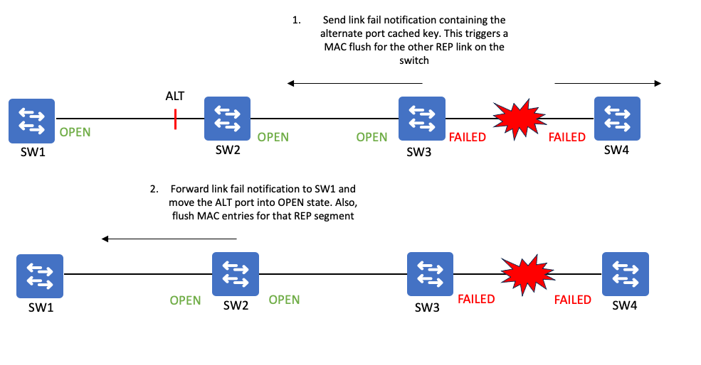
REP Link Failure Notification
When a link fails in a REP segment it moves into "Failed" state and beings sending link failure notifications containing the cached key of the Alternate port. The sending switch also flushes MAC addresses for its REP link that is still up.
The REP neighbor switch receives the link failure notification and forwards it to any REP neighbors on the segment as well as flushes MAC address entries for ports in the REP segment. If the switch receiving the link failure notification contains the Alternate port on the segment it moves the port into an "OPEN" state.
Link failure notifications are distributed in two ways:
- REP Fast Notifications via sending BPA messages to the Cisco multicast address of 0100.0ccc.ccce
- REP Reliable Notifications via sending BPA messages in REP BPDU frames (similar to REP LSL frames).
|
Feature
|
Fast Notification
|
Reliable Notification
|
|
Hardware Forwarded
|
Yes
|
No
|
|
Reliable
|
No
|
Yes via sequence numbering and retransmissions
|
|
Passes through an Alternate/Blocking port
|
No
|
Yes
|
|
Forwarded outside of REP segment
|
Yes
|
No
|
|
Sent on REP Admin VLAN
|
Yes
|
No (uses native VLAN)
|
REP Link Failure Notifications act similar to STP TCNs in that they get punted to the CPU and trigger MAC flushing on REP ports. With additional configuration on REP ports facing STP segments, a REP link failure notification can be converted into an STP TCN to inform the STP domain to flush MACs due to the REP link failure.
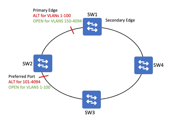
REP Preferred Port and VLAN Load Balancing
When VLAN Load Balancing is configured, the REP Primary edge port is the the port that can initiate load balancing. The REP Preferred port is the port that is preferred to become the alternate port.
The primary edge port is relevant in the load balancing scenario because load balancing is initiated from the primary edge port via additional configuration.
Load Balancing is achieved by configuring which VLANs the preferred port must block.
- The remaining VLANs become blocked at the primary edge port.
- There are 2 Alternate ports when VLAN load balancing is configured and active.
Once load balancing is configured, it does not take affect until a link failure or manual preemption is triggered from the primary edge port.
Configure
Network Diagram
Configurations
All ports must be configured as trunk ports with a matching REP segment ID. The edge switch requires the edge parameter.
9200-STACK-1#show running-config interface port-channel 1
Building configuration...
Current configuration : 100 bytes
!
interface Port-channel1
 switchport mode trunk        <-- Must be a trunk
 load-interval 30
 rep segment 1 edge           <-- configure edge port in REP segment 1
end
REP ports that are not edge ports do not require the edge keyword.
9300-STACK-2#show running-config interface port-channel 1
Building configuration...

Current configuration : 69 bytes
!
interface Port-channel1
 switchport mode trunk
 rep segment 1                <-- non-edge REP port configuration
end
Verify
Once all segment ports are configured the segment is complete and no failed ports can be present.
Confirm the REP topology.
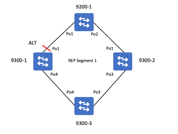
9200-STACK-1#show rep topology
REP Segment 1
BridgeName                       PortName   Edge Role
-------------------------------- ---------- ---- ----
9200-STACK-1                     Po1        Pri  Open     <-- primary edge port
9300-STACK-1                     Po1             Alt      <-- alternate port that is blocking VLANs
9300-STACK-1                     Po4             Open
9300-STACK-3                     Po4             Open
9300-STACK-3                     Po3             Open     <-- port is OPEN and forwarding all VLANs
9300-STACK-2                     Po3             Open
9300-STACK-2                     Po1             Open
9200-STACK-1                     Po2        Sec  Open     <-- secondary edge port
Confirm REP status on an interface.
9200-STACK-1#show interface port-channel 1 rep                            <-- check REP status for the port
Interface                    Seg-id Type           LinkOp      Role
---------------------------- ------ -------------- ----------- ----
Port-channel1                1      Primary Edge    TWO_WAY     Open      <-- Edge port is not blocking any VLANs
Detail output gives further insight into REP status of the port
9200-STACK-1#show interfaces port-channel1 rep detail
Port-channel1   REP enabled
Segment-id: 1 (Primary Edge)
PortID: 08E978BC1A4FDD80             <-- port ID made from system MAC + random number
Preferred flag: No
Operational Link Status: TWO_WAY
Current Key: 0BE934ED1B4798003405    <-- cached key of the segment Alternate port
Port Role: Open
Blocked VLAN:
Admin-vlan: 1                        <-- REP admin vlan
Preempt Delay Timer: disabled
LSL Ageout Timer: 5000 ms            <-- default link status adjacency hold down timer
LSL Ageout Retries: 5
Configured Load-balancing Block Port: none    <-- no load balancing configured on the port
Configured Load-balancing Block VLAN: none
STCN Propagate to: none                       <-- sending TCNs into STP domain is disabled
LSL PDU rx: 924743, tx: 612406
HFL PDU rx: 1, tx: 1
BPA TLV rx: 611945, tx: 2
BPA (STCN, LSL) TLV rx: 0, tx: 0
BPA (STCN, HFL) TLV rx: 0, tx: 0
EPA-ELECTION TLV rx: 13, tx: 11
EPA-COMMAND TLV rx: 0, tx: 0
EPA-INFO TLV rx: 152998, tx: 152999
Command Summary
show rep topology
show rep topology detail
show rep topology segment <Id>
show rep topology segment <Id> detail
show rep topology archive
show rep topology archive detail
show interfaces gig<X/X> rep
show interfaces gig<X/X> rep detail
Troubleshoot
Input Queue Wedge
On certain versions of code, the REP HSL packet can wedge an interface input queue.
- This can impact REP convergence if HSL packets fill the input queue and LSL convergence packets cannot be processed
- This is caused by Cisco bug ID CSCwc52868
- The input queue handles processing of ALL protocols. Once the queue becomes "full" it starves out legitimate network control traffic and cannot be emptied manually.
Symptoms of Queue wedge
- Protocols such as CDP, IGMP, etc stop working (you can lose a neighbor in CDP, IGMP multicast programming issues, and so on).
- The symptoms vary depending on what features and protocols are arriving to the interface which need to be processed.
- The interface input queue is used for packets that arrive at an interface to be queued and punted to the CPU for processing
- An input queue becomes wedged when a certain packet cannot be dequeued and eventually the input queue limit is reached
- Once an interface input queue limit is hit, no other packets can be stored and they are instead dropped.
Verify a Queue wedge
REP hardware flooded layer packets over the REP administrative VLAN causes the input queue on a L2 port to become wedged.
C9300#show interface gi1/0/48
GigabitEthernet1/0/48 is up, line protocol is up (connected)
  Hardware is Gigabit Ethernet, address is 7486.0b0c.e0b0 (bia 7486.0b0c.e0b0)
  Description: PORT
  MTU 1500 bytes, BW 1000000 Kbit/sec, DLY 10 usec,
     reliability 255/255, txload 1/255, rxload 1/255
  Encapsulation ARPA, loopback not set
  Keepalive set (10 sec)
  Full-duplex, 1000Mb/s, media type is 10/100/1000BaseTX
  input flow-control is on, output flow-control is unsupported
  ARP type: ARPA, ARP Timeout 04:00:00
  Last input 01:14:45, output 00:00:00, output hang never
  Last clearing of "show interface" counters never
  Input queue: 2438/2000/16/0 (size/max/drops/flushes); Total output drops: 0     <-- 2438 frames in the input queue who's limit is 2000
<...snip...>
Check this CLI to confirm if an interface is holding buffers with REP HFL frames.
- The destination MAC for HFL frames is 0100.0ccc.ccc:
C9300#show buffers input-interface gi1/0/48 packet
Tracekey : 1#09f7811786f1de5ddfa0f5542a69f593

Buffer information for Middle buffer at 0x7F81FE8E9000
  data_area 0x7F820F78F004, refcount 1, next 0x0, flags 0x210
  linktype 189 (LINK_REP), enctype 3 (SNAP), encsize 22, rxtype 88
  if_input 0x7F820E71DB50 (GigabitEthernet1/0/48), if_output 0x0 (None)
  inputtime 3d14h (elapsed 03:11:48.761)
  outputtime 00:00:00.000 (elapsed never), oqnumber 65535
  datagramstart 0x7F820F78F072, datagramsize 565, maximum size 804
  mac_start 0x7F820F78F072, addr_start 0x7F820F78F072, info_start 0x7F820F78F080
  network_start 0x7F820F78F088, transport_start 0x0, caller_pc :55FBF3ED3000+37680AC

  7F820F78F072: 01000CCC CCCEA0F8 ...LLN x           <--- HFL destination MAC is in the queue
Remediate the queue wedge:
- Reboot the device (An input queue cannot be cleared without a reload. Shut / no shut of interface does not clear these buffers)
- Upgrade to a version of code not impacted by this issue
- Adjust input queue size (In cases where you are certain no more HSL frames are going to arrive you can try increasing the input queue size. Keep in mind the problem is likely to manifest again the next time an HSL flood occurs).
In this state, there are some REP syslogs that occur. These logs are called out in the next section

Note: Keep in mind that this is a generic log indicating a loss of LSL between neighbors, which can happen for other reasons. So it is useful to identify this specific problem, but is not limited to this issue
REP Log Messages
|
Log Message
|
Definition
|
Recovery Actions
|
|
%REP-4-LINKSTATUS: TenGigabitEthernet1/1/1 (segment 1) is non-operational due to neighbor not responding
|
Indicates a loss of LSL between neighbors
|
- Confirm interfaces do not have a wedged input queue
- Verify links are free from CRCs & other incrementing errors
- Verify there are no CoPP or drops in the CPU punt path
|
|
%REP-5-EDGEMISCONFIG: Invalid topology. More than two edge ports configured for segment
|
shown when the edge port advertisement received is not same as edge port advertisement sent out
|
- Expected behavior when multiple ports in a topology are recovering from failed state this message is can be seen, but not after the topology has established
- every failed port in rep topology acts as an edge port and sends out an advertisement
|
Related Information
 Feedback