Configure OSPF on Catalyst 1300X Switches Using the Web UI
Available Languages
Objective
The objective of this article is to configure Open Shortest Path First (OSPF) on Cisco Catalyst 1300X series switches via the web user interface (UI).
Applicable Devices | Software Version
- Cisco Catalyst 1300X Series Switches | 4.10.0.82
Introduction
OSPF is a dynamic link-state routing protocol widely used in networks for efficient and scalable route calculation. The Cisco Catalyst 1300X Series Switches support OSPFv2 (for IPv4) and OSPFv3 (for IPv6), allowing seamless interoperability with other OSPF-compliant devices. While advanced OSPF features are typically configured via CLI, the web UI provides a straightforward interface for basic OSPF setup, including process creation, area assignment, and interface configuration. This guide focuses on OSPFv2 (IPv4) configuration using the web UI, ensuring optimal routing performance and network stability.
For more information on OSPF, check out the following articles:
- Understanding OSPF in Catalyst 1300X Switches
- Configure OSPF on Cisco Catalyst 1300X Series Switches Using CLI
OSPFv2 Configuration Flow
- Create an OSPF process and assign it a router ID. Multiple process can be created. The configurations below can be applied per each process.
- Add one or more areas to the process. For each area:
- Adding area networks from the IP addresses that are configured on the device’s interfaces.
- Define the area type and settings.
- Configure the network settings.
- OSPFv2 Process
- OSPFv2 Area
- OSPFv2 IPv4 Networks
Configure OSPFv2 Using Web UI
Step 1
Login to the Catalyst 1300X switch and go to Advanced mode.

The default username and password is cisco/cisco.
Step 2
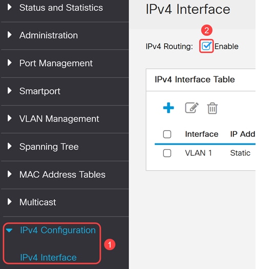
OSPFv2 is active only if IP routing is enabled on the device. To do this, navigate to IPV4 Configuration > IPv4 interfaces and enable IPv4 Routing.
Step 3
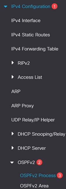
Navigate to IPv4 Configuration > OSPFv2 > OSPFv2 Process.
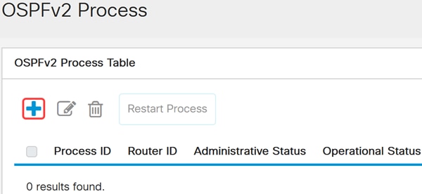
Step 4
Click Add to create a new OSPFv2 process.
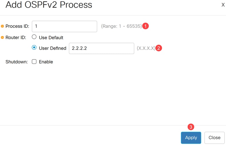
Step 5
Configure the following for an OSPFv2 process:
- Process ID - Internally used identification parameter. It is locally assigned and can be any positive integer. The default value is 1 and the range is 1-65535.
- Router ID - The router ID assigned to the process. Use either the default router ID or configure the router ID manually.
- Shutdown - Enable this to create the process at the shutdown state.
Click Apply.
Modifying the router ID of a running OSPFv2 process will automatically restart the process.
The Shutdown option allows you to configure the process settings without activating the traffic.
Step 6
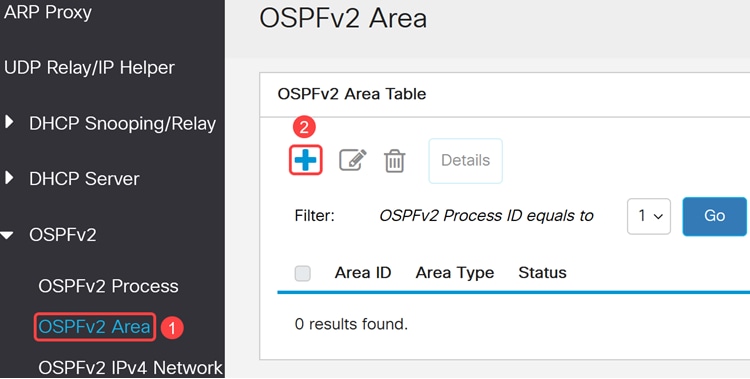
An OSPFv2 Area table is a data structure used in OSPFv2 to organize and manage routing information within different areas of an IPv4 network. OSPFv2 uses areas to optimize and manage routing efficiently.
Navigate to OSPFv2 Area and click Add to create one or more areas.
Step 7
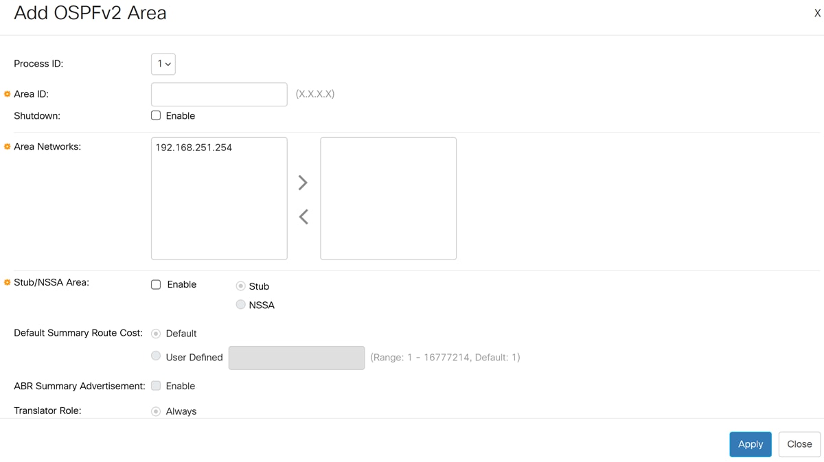
Configure the following fields in the Add OSPFv2 Area pop-up window:
- Process ID - select the OSPFv2 process ID from the dropdown box the area will be associated with the selected process ID.
- Area ID - Use the dotted decimal notation to define the area ID in Catalyst 1300X switches. For example, to add an interface to area 0, the area ID will be 0.0.0.0.
- Shutdown - select enable to create the area in the shutdown state. This allows to configure the area settings while keeping the area in the inactive state.
- Area Networks - select one or more Ipv4 networks to add to the area.
- Stub/NSSA Area: - select to set this area as a stub area or NSSA (Not So Stubby Area). This option is available only if the area is not a backbone area (area ID does not equal 0.0.0.0). If this option is selected, continue to configure the following fields:
- Stub/NSSA - select if this area is a stub area or NSSA.
- Default Summary Route Cost - specify a cost for the default summary route that is sent into a stub area or not-so-stubby area (NSSA). Select one of the available options.
- Default - value of 1
- User defined - Range: 1 - 16777214
- ABR Summary Advertisement- enables Area Border Router (ABR) to send summary link advertisements into the stub area.
- Translator Role - Specifies whether or not an NSSA border router will unconditionally translate Type-7 LSAs into Type-5 LSAs.
- Select Always to specify that NSSA border router always translates Type-7 LSAs into Type-5 LSAs regardless of the translator state of other NSSA border routers.
- Select Candidate to specify that an NSSA border router participates in the translator election process described in RFC 3101, Section 3.1.
- Translator Stability Interval - Specifies the number of seconds after an elected translator determines its services are no longer required, that it should continue to perform its translation duties. The default value is 40 seconds.
The Translator Role and Translator Stability Interval can be configured only if the area was defined as an NSSA.
Click Apply to create the area.
Area 0 (0.0.0.0) is the backbone area and must be present in all OSPF deployments. Use stub or NSSA areas to optimize routing in specific network segments.
Step 8
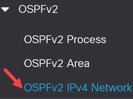
Go to OSPFv2 IPv4 Networks in the navigation pane to view, edit or configure the OSPFv2 IPv4 area networks.
Step 9
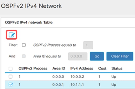
To edit the OSPFv2 IPV4 Area Network Table, select the OSPFv2 process from the table, click the Edit icon.
Step 10
Configure the following:
- Select the Process ID, Area ID, and Area network to configure.
- Configure the interface cost- selected the Default cost or a User Defined cost (Range 1-65535). The path cost is calculated using the formula Cost = Reference Bandwidth / Interface Bandwidth, with a reference bandwidth of 10 Gbps.
- Shutdown - Optionally set the OSPFv2 Network to administrative down state.
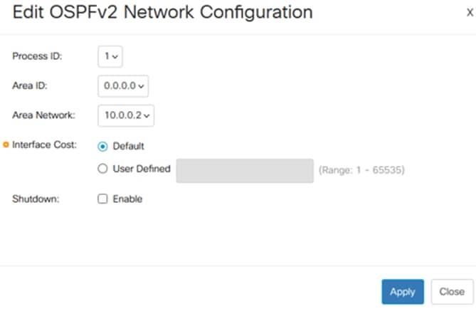
Interface cost influences OSPF path selection. Adjust costs to control routing preferences if necessary.
Best Practices
- Use unique router IDs for each OSPF process in the network.
- Designate Area 0 as the backbone and connect all other areas to it.
- Use stub or NSSA areas to reduce routing overhead in smaller segments.
- Regularly back up the configuration after changes.
- Monitor OSPF process and interface status for optimal performance.
- For advanced OSPF features (e.g., route summarization, redistribution), use the CLI as the GUI may have limitations.
- Increased OSPF usage can impact CPU and memory. Plan network design and OSPF roles accordingly.
Conclusion
Now you know how to use the web UI to configure basic OSPF settings in the Catalyst 1300X switches.
For more information on OSPF feature in Catalyst 1300X switches, refer to the Catalyst 1300X Admin Guide and CLI Guide.
Revision History
| Revision | Publish Date | Comments |
|---|---|---|
1.0 |
12-Dec-2025
|
Initial Release |
 Feedback
Contact Cisco
- Open a Support Case

- (Requires a Cisco Service Contract)