Site-to-Site Connectivity with Overlapping Subnets in Cisco Secure Access
Available Languages
Introduction
This document describes the Cisco Secure Access overlapping subnet solution.
Prerequisites
Requirements
Cisco recommends that you have knowledge of these topics:
- Cisco Secure Access administration.
- Firewall / Router administration.
Cisco recommends that you have:
- Administrative Access to Cisco Secure Access.
- Administrative Access to the IPSec Headend device (Firewall or Router )
Components Used
This document is not restricted to specific software and hardware versions.
The information in this document was created from the devices in a specific lab environment. All of the devices used in this document started with a cleared (default) configuration. If your network is live, ensure that you understand the potential impact of any command.
Before you Begin
In this example there are two different branch sites with the same IP subnet 192.168.200.0/24, in which they are connected to the Cisco Secure Access via two separate IPSec Tunnel.
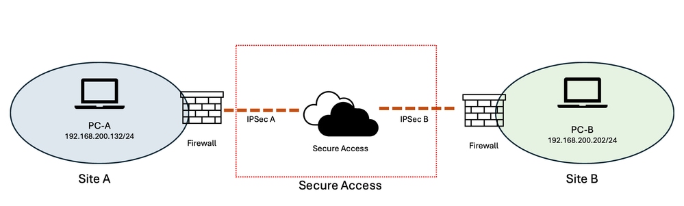 Image - Network Diagram
The goal is, users from "Site A" can access the resources in "Site B" and vise versa.
Preparing and Plannig
Because both sites use the same IP subnet (192.168.200.0/24), the overlapping address space prevents direct communication between the two sites. To resolve this overlap, two non-overlapping virtual subnets are assigned to represent the resources at each site.
For this example:
-
Site A:
10.30.30.0/24 -
Site B:
10.40.40.0/24 -
Actual subnet at both sites:
192.168.200.0/24
The virtual subnets provide unique address spaces for each site while the actual resources continue to use their existing 192.168.200.0/24 addresses.
When a user at Site A accesses a resource located at Site B, the user accesses the resource through the Site B virtual subnet (10.40.40.0/24) rather than directly using the overlapping 192.168.200.0/24 address space.
Cisco Secure Access provides a One-to-One Destination NAT (D-NAT) feature that can translate the virtual addresses to the corresponding real addresses. The D-NAT address range has the same size as the original subnet. In this example, both the virtual and actual networks are /24 subnets, providing a one-to-one mapping between the virtual and real IP addresses.
For example:
10.40.40.202 → 192.168.200.202
Therefore, a request from Site A destined for 10.40.40.202 is translated by D-NAT to 192.168.200.202, allowing the request to reach the corresponding resource at Site B despite both sites using the same underlying IP subnet.
This approach effectively creates a virtual, non-overlapping address space for each site while preserving the existing IP addressing of the resources. It also provides a consistent one-to-one relationship between the virtual and real addresses, making the configuration easier to understand, manage, and troubleshoot.
Configuration Steps
Due to the current design and limitations of Cisco Secure Access, achieving this scenario requires configuration on both the headend devices behind the IPsec tunnels and Cisco Secure Access.
The headend device is the firewall or router that establishes the IPsec tunnel to Cisco Secure Access. In addition to configuring D-NAT in Cisco Secure Access, the headend firewall must also perform Source NAT (S-NAT) for the return traffic.
The configuration therefore consists of two sections:
-
Configuring Destination NAT (D-NAT) in Cisco Secure Access for each network tunnel separately.
-
Configuring Source NAT (S-NAT) on the firewalls to ensure that return traffic is translated back to the virtual address space.
Configuring Cisco Secure Access
Step 1: From the Cisco Secure Access management portal, navigate to Connect > Network Connections and select the Network Tunnel Groups tab.
Step 2: Edit the Network Tunnel Group associated with the IPsec tunnel for the site that uses the overlapping subnet.
In this example:
-
IPSec-A = Network Tunnel Group for Site A
-
IPSec-B = Network Tunnel Group for Site B
Step 3: Click the three-dot menu next to the required Network Tunnel Group and select Edit.
Step 4: From the left-hand menu, select the Routing tab and enable Network Address Translation (NAT) if it is not already enabled.
Step 5: Under Destination NAT Mappings, click Add Mappings.
Step 6: Use this table to configure the D-NAT mappings for each Network Tunnel Group:
| Site A - IPSec Tunnel |
Site B - IPSec Tunnel |
|
| Destination NAT-1 |
Site → Secure Access Original CIDR: 10.40.40.0/24 Translated CIDR: 192.168.200.0/24 |
Site → Secure Access Original CIDR: 10.30.30.0/24 Translated CIDR: 192.168.200.0/24 |
| Destination NAT-2 |
Secure Access → Site Original CIDR: 192.168.200.0/24 Translated CIDR: 10.30.30.0/24 |
Secure Access → Site Original CIDR: 192.168.200.0/24 Translated CIDR: 10.40.40.0/24 |
 IPsec Tunnel Site A - D-NAT Configuration IPsec Tunnel Site A - D-NAT Configuration |
 IPsec Tunnel Site B - D-NAT Configuration IPsec Tunnel Site B - D-NAT Configuration |
Configuring the Firewall
The firewall configuration is required because of a current limitation in the handling of overlapping IP subnets behind Network Tunnel Groups.
When Cisco Secure Access performs D-NAT on an incoming packet, the translated destination address is used to deliver the packet to the destination resource. However, the corresponding reverse translation is not automatically performed for the return traffic in this overlapping-subnet scenario.
As a result, the return traffic needs to be manually source-NATed on the firewall.
The key requirement is that the destination server sees the return traffic using the virtual IP address that the client originally accessed, rather than the server actual IP address.
Example
Assume the following:
-
Site A client:
192.168.200.132 -
Site B web server:
192.168.200.202 -
Site B virtual subnet:
10.40.40.0/24 -
Virtual address of the web server:
10.40.40.202
The client at Site A accesses the Site B web server using https://10.40.40.202
Cisco Secure Access performs the D-NAT 10.40.40.202 → 192.168.200.202
The packet then reaches the web server at 192.168.200.202.
The problem occurs with the return traffic. Without additional NAT on the firewall, the web server generates the response with Source: 192.168.200.202
However, the client initiated the connection to Destination: 10.40.40.202
Therefore, the return traffic needs to be translated so that the source address presented to the client corresponds to the virtual address192.168.200.202 → 10.40.40.202
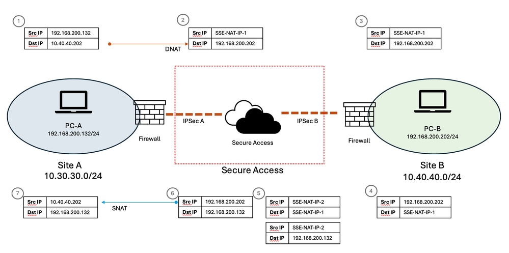 Image - Network Flow
To achieve this, the firewall performs Source NAT on traffic leaving toward the Network Tunnel Group.
For this example, the required mapping is192.168.200.0/24 → 10.40.40.0/24
This creates the reverse one-to-one relationship between the real addresses and their corresponding virtual addresses.
One-to-One SNAT
If the firewall supports one-to-one Source NAT for the entire subnet, a single NAT rule can represent the complete /24 address range.
For example:
| Real Source | Translated Source |
|---|---|
192.168.200.0/24 |
10.40.40.0/24 |
This results in mappings such as 192.168.200.202 → 10.40.40.202 and 192.168.200.203 → 10.40.40.203
The same one-to-one relationship applies across the entire subnet.
Firewalls Without One-to-One SNAT
If the firewall does not support one-to-one Source NAT for the entire subnet, each required mapping needs to be configured individually.
For example, for the web server:
-
Source IP:
192.168.200.202 -
Source interface: Network Tunnel Group
-
Traffic direction: Inbound
-
Translated Source IP:
10.40.40.202
The resulting translation is192.168.200.202 → 10.40.40.202
The same approach can be applied to each resource that requires access through the virtual subnet.
This ensures that both directions of the communication maintain the virtual addressing scheme and that the client receives the response from the same virtual IP address that it used when establishing the connection.
Related Information
Cisco Secure Access NAT Mapping / Network Tunnel Group configuration : https://securitydocs.cisco.com/docs/csa/olh/168842.dita
Cisco Secure Access Network Tunnel Group configuration and routing reference: https://securitydocs.cisco.com/docs/csa/olh/118900.dita
Cisco Secure Access troubleshooting and basic-data collection guide: https://www.cisco.com/c/en/us/support/docs/security/secure-access/221240-troubleshoot-and-collect-basic-informati.html
Revision History
| Revision | Publish Date | Comments |
|---|---|---|
1.0 |
13-Aug-2026
|
Initial Release |

 Feedback
Contact Cisco
- Open a Support Case

- (Requires a Cisco Service Contract)