Configure Secure Access with Secure FTD and ASA for Private Access with NAT
Available Languages
Contents
Introduction
This document describes how to configure Secure Access Network Tunnel Group with Network Address Translation.
Prerequisites
Requirements
Cisco recommends that you have knowledge of these topics:
- Cisco Firewall Management Center
- Cisco Secure Firewall Threat Defence
- Cisco Secure Access
- Cisco Adaptive Security Appliance
- Network Address Translation
- Policy Based Routing
- Packet Captures on Firewall
Components Used
The information in this document is based on:
- Cisco Firewall Management Center 7.10
- Cisco Secure Firewall Threat Defence 7.10
- Cisco Secure Access
- Cisco Adaptive Security Appliance 9.22
- Cisco Routers
The information in this document was created from the devices in a specific lab environment. All of the devices used in this document started with a cleared (default) configuration. If your network is live, ensure that you understand the potential impact of any command.
Background Information
Cisco Secure Access delivers cloud-native Secure Service Edge capabilities including Secure Internet Access (SIA) and Secure Private Access (SPA). For organizations extending private application access to remote users without backhauling all traffic through a datacenter, Secure Access uses IPsec Network Tunnel Groups (NTGs) to create encrypted tunnels between on-premises network devices—such as Cisco Firewall Threat Defense (FTD), Adaptive Security Appliance (ASA)—and Cisco Secure Access cloud Points-of-Presence (PoPs).
This document details how to establish a route-based IPsec tunnel using IKEv2 between Cisco FTD, ASA, and Cisco Secure Access, enabling Network Address Translation (NAT) on Secure Access and Policy-Based Routing (PBR) on the FTD and ASA to steer only private-access-bound traffic into the tunnel.
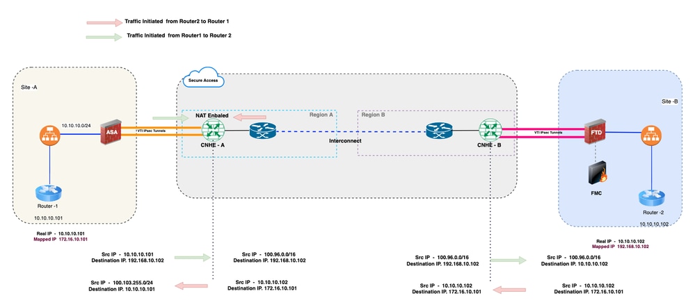
Network Diagram
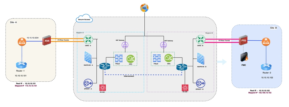
Network Topology
Configure
Secure Access and Secure Firewall Thread Defense - Dynamic (BGP) route-based VPN with PBR
Configure Network Tunnel Group on Secure Access
1. Log in to Secure Access dashboard Secure Access
2. Navigate to Connect > Network Connections > Network Tunnel Groups and click on +Add to configure the Network Tunnel Group.
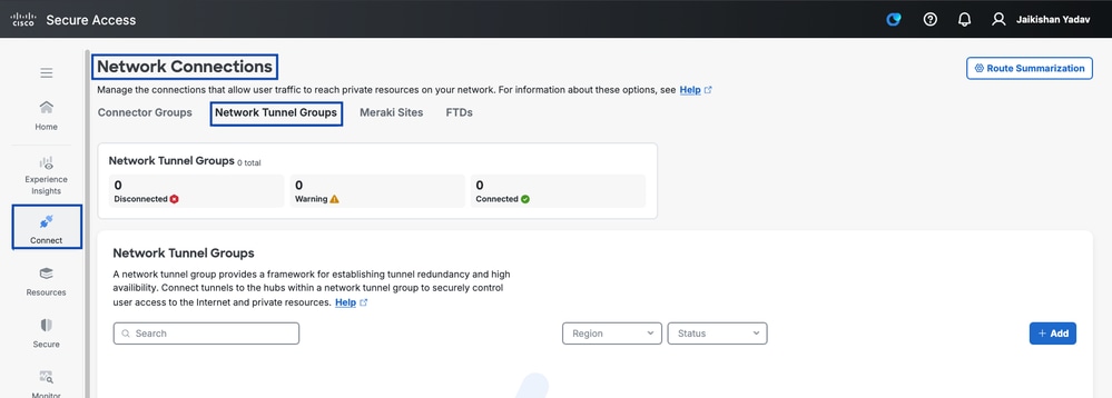
Secure Access - Network Tunnel Groups
3. Configure Network Tunnel Group - General Settings
- Configure Tunnel Group Name, Region and Device Type
- Click Next
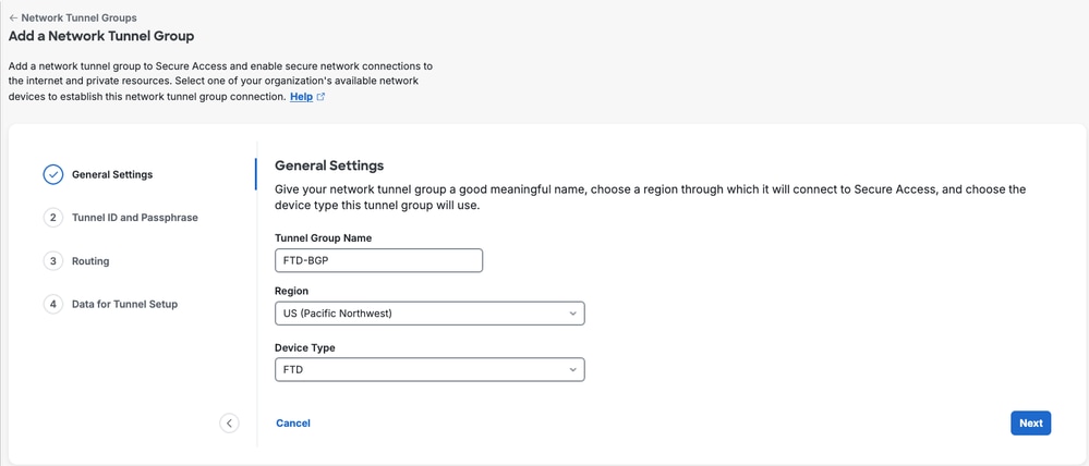
Secure Access - Network Tunnel Groups General Settings
4. Configure Tunnel ID and Passphrase.
- Configure the Tunnel ID and Passphrase.
- Click Next
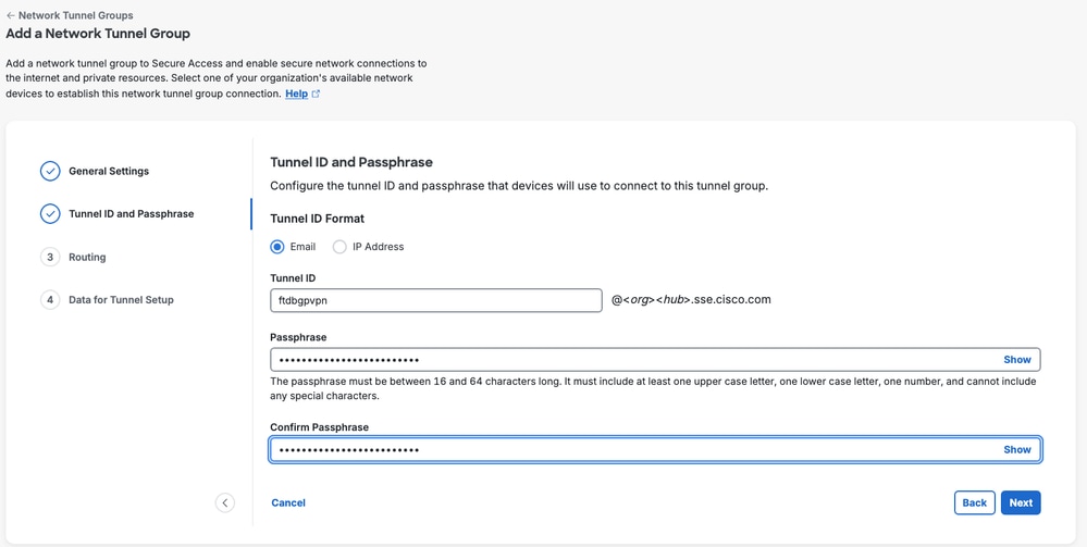
Secure Access - Network Tunnel Groups ID and Passphrase
5. Configure Routing
- Configure Device AS Number
- Click Save
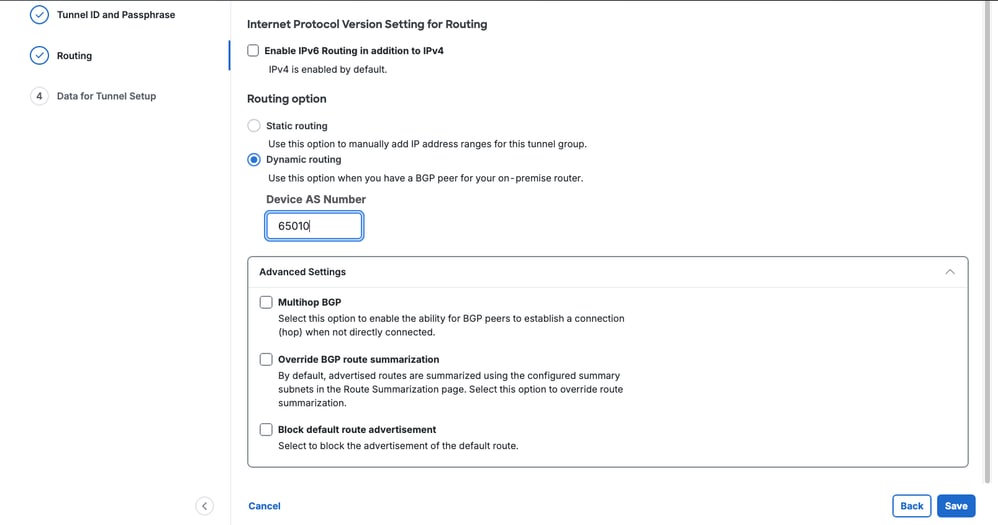
Secure Access - Network Tunnel Groups Routing
6. Save Network Tunnel Group Configuration
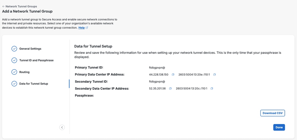
Secure Access - Network Tunnel Groups
Configure Dynamic Route-based IPsec VPN on Secure Firewall Threat Defense (FTD) with PBR
1. Login to Firewall Management Center (FMC)
2. Configure Virtual Tunnel Interface VTI
- Navigate to Devices > Device Management
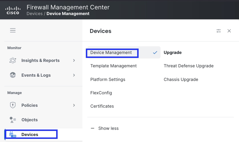
Secure Firewall Management - Dashboard
- Click the Pencil icon next to device and navigate to Interface section
- Click on Add interfaces and select Virtual Tunnel Interface
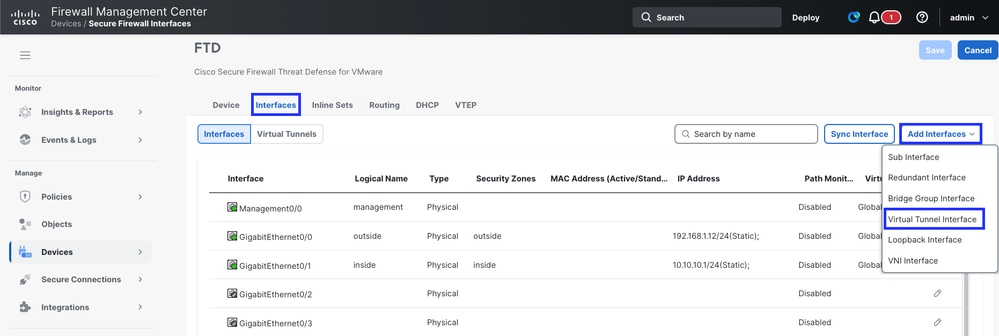
Secure Firewall Management - FTD VTI Configuration
- Configure VTI
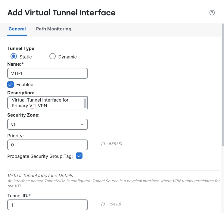
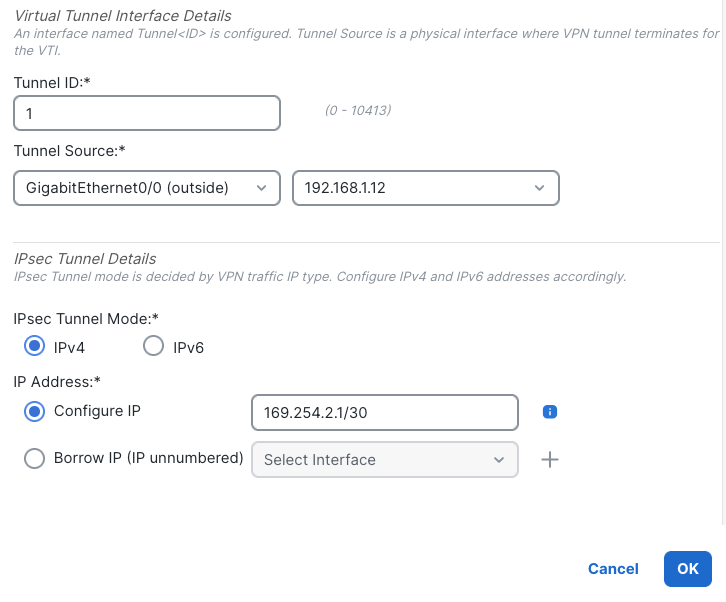
Secure Firewall Management - FTD VTI Configuration
- Configure VTI-2 as well for secondary IPsec VPN with Secure Access
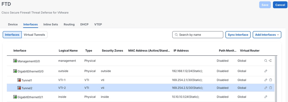
Secure Firewall Management - FTD VTI Configuration
3. Navigate to Secure Connections > Site-to-Site VPN & SD-WAN and click on Add to confiure the VPN
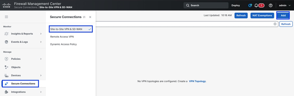
Secure Firewall Management - FTD VPN Configuration
- Create VPN topology
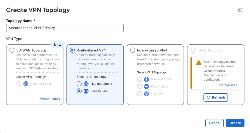
Secure Firewall Management - FTD VPN Configuration
- From step 6 of the Configure Network Tunnel Group on Secure Access , obtain the tunnel IDs and IP addresses for the primary and secondary data centers.
- Click on Endpoints
- Under Node A, click Device and select your FTD device
- Click on Virtual Tunnel Interface and select the first VTI interface created in the previous step
- Click on Send Local Identity to Peers option and select Email ID, enter the primary tunnel ID (from "Save Network Tunnel Group Configuration" under the Configure Network Tunnel Group on Secure Access )
- Under Node B, click on Device and select Extranet
- Click on Device Name and give it a name
- Click on Endpoint IP Addresses and enter the Secure Access Primary and Secondary IP Addresses separated by a comma (from "Save Network Tunnel Group Configuration" under the Configure Network Tunnel Group on Secure Access )
- Click on Add Backup VTI
- Click on Virtual Tunnel Interface and select the second VTI interface created in the previous step
- Click on Send Local Identity to Peers option and select Email ID, enter the secondary tunnel ID (from "Save Network Tunnel Group Configuration" under the Configure Network Tunnel Group on Secure Access )
- Click on Save
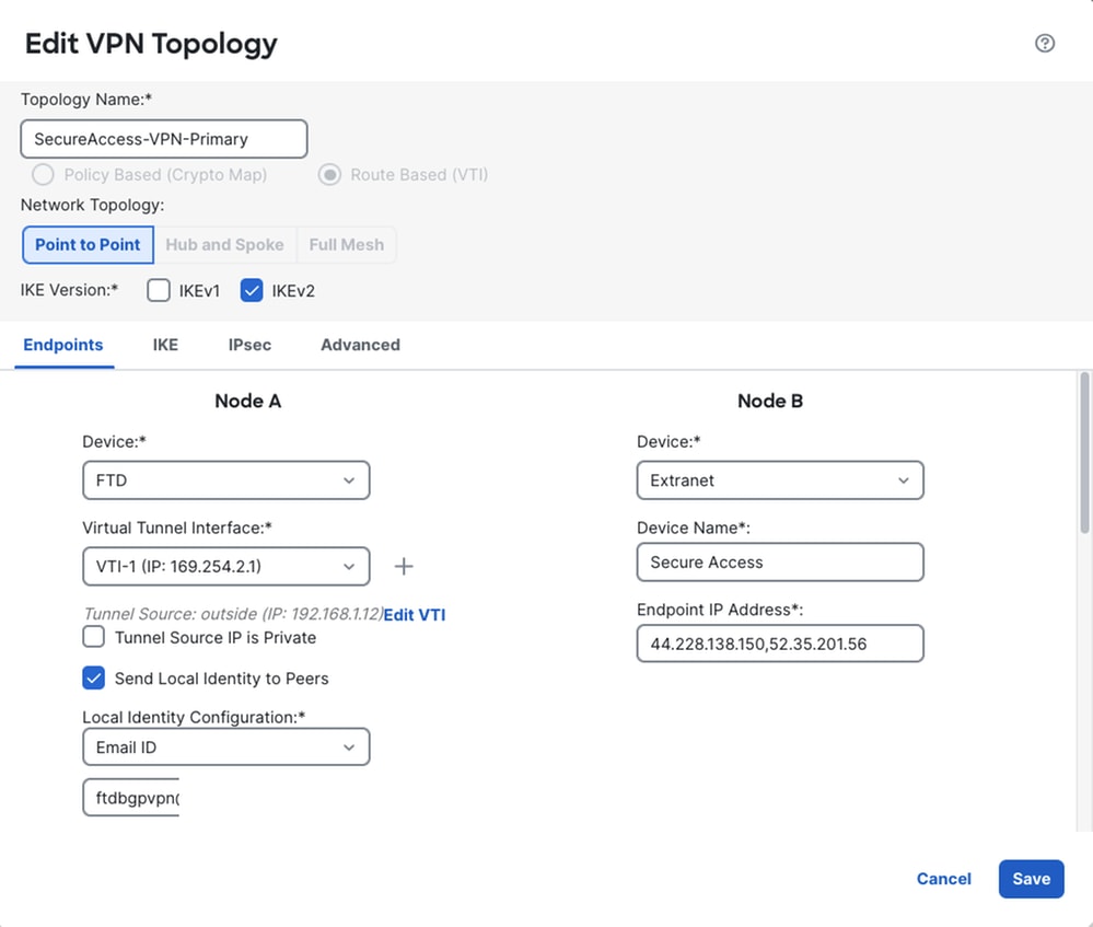
Secure FTD - VPN Endpoint Configuration
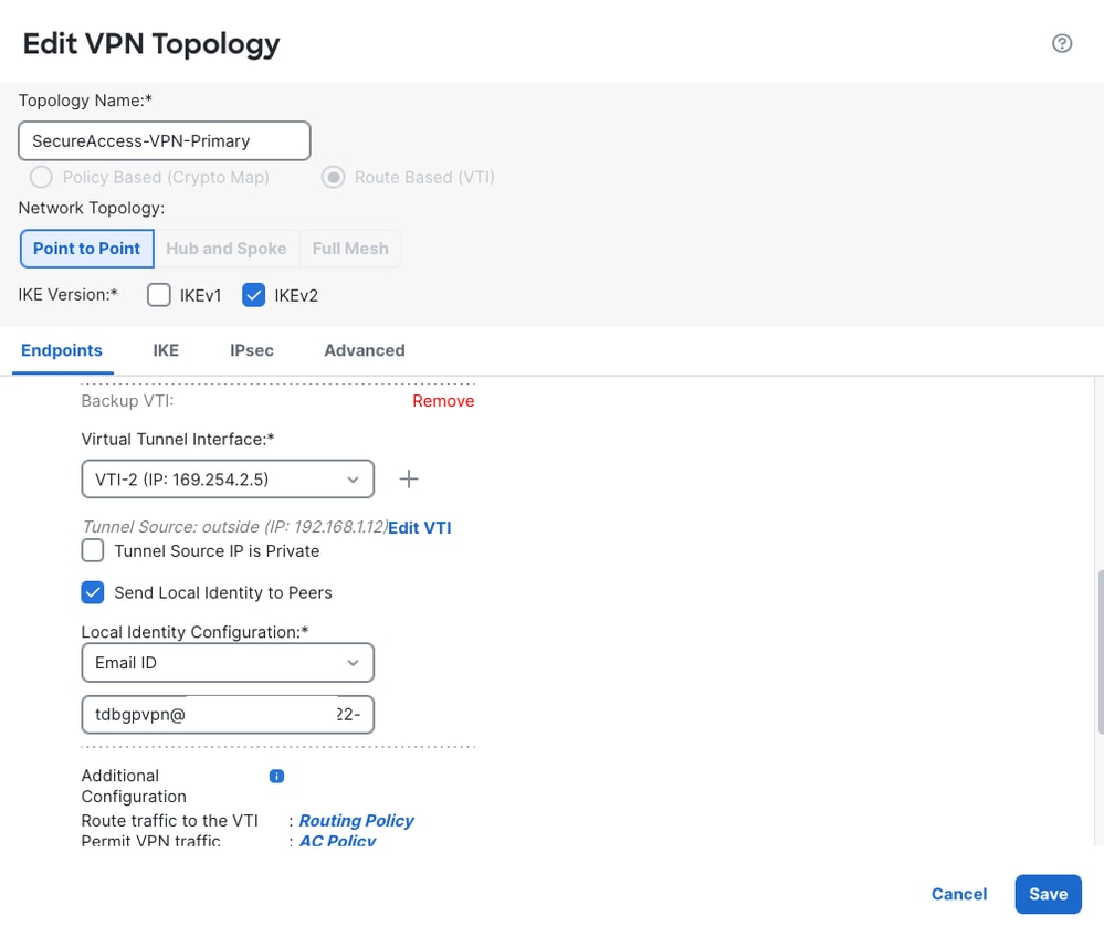
Secure FTD - VPN Endpoint Configuration
- Configure IKEv2 Settings as per Supported IPsec Parameters
- Select Policies as Umbrella-AES-GCM-256
- Select Authentication Type as Pre-Shared Manual Key
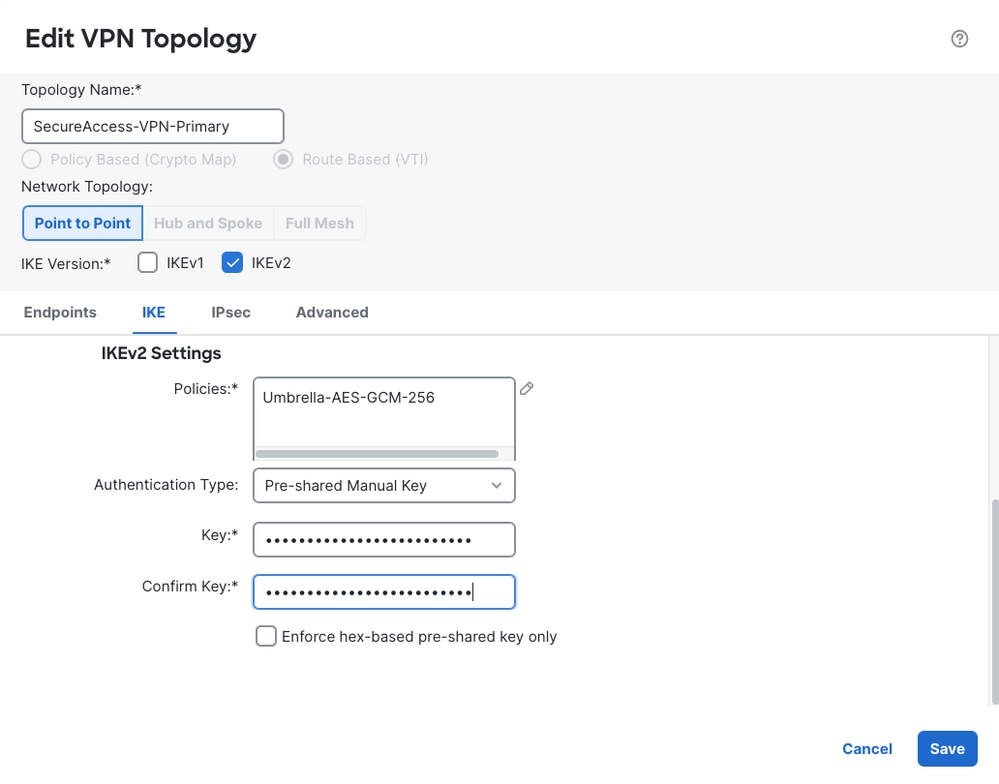
Secure FTD - VPN IKE Settings
- Configure IPsec settings
- Select IKEv2 IPsec Proposals as Umbrella-AES-GCM-256
- Enable PFS as select Modulus Group as 20
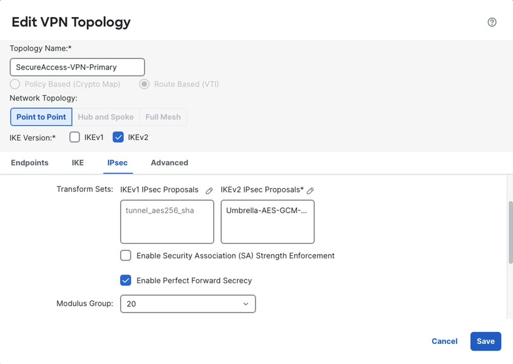
Secure FTD - VPN IPsec Settings
- Advanced Settings
- Click Save
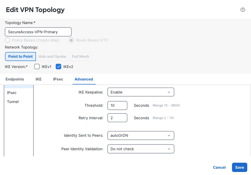
Secure FTD - VPN Advanced Settings
FTD Policy Based Routing
In traditional routing, packets are routed based on the destination IP address. Changing the routing of specific traffic in a destination-based routing system is difficult. Policy Based Routing (PBR) extends and complements the mechanisms provided by routing protocols, giving you more control over routing.
PBR allows you to set the IP precedence. It also allows you to specify a path for certain traffic, such as priority traffic over a high-cost link. With PBR, you can define routing that is based on criteria other than destination network such as source port, destination address, destination port, protocol, applications, or a combination of these objects. For more information, refer Policy Based Routing
1. Configure Access List
- Navigate to Objects > Access List > Extended
- Click on Add Extended Access List
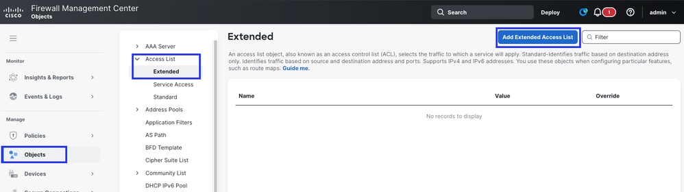
Secure FTD - Extended Access List
- Give the Access List Name
- Define the Action
- Allow. - Traffic defined will be sent to IPsec tunnel
- Block - Traffic will be bypassed from IPsec Tunnel
- Rule will be matched based on Sequence Number (Lower to higher)
- Click on Add
- Click Save
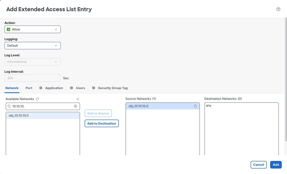
Secure FTD - Extended Access List

Secure FTD - Extended Access List
2. Configure Policy Based Routing
- Navigate to Devices > Device Management > FTD > Routing
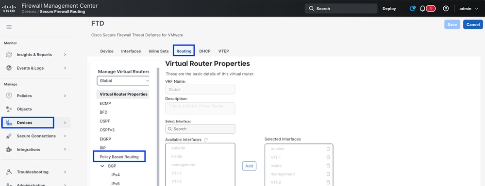
Secure FTD - Policy Based Routing
- Click Add
- Select Ingress Interface - Ingress interface for the subnet we defined in the Access List
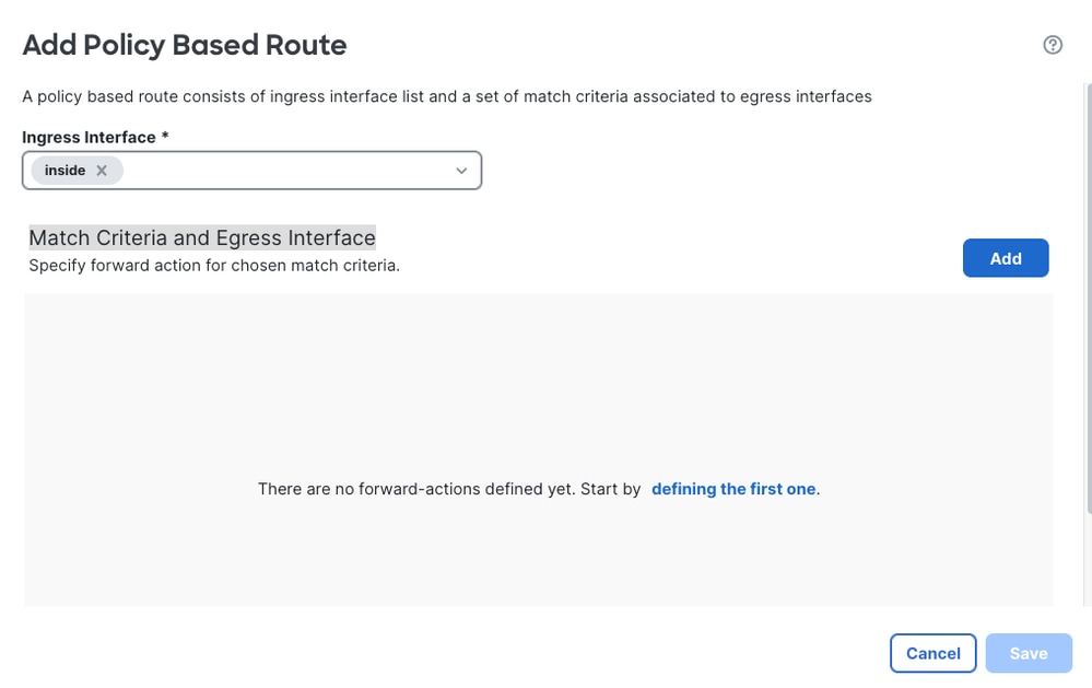
Secure FTD - Policy Based Routing
- Define Match Criteria and Egress Interface
- Click on Add
- Select the Match ACL
- Select Send to as IP address
- Add Next hop IP address. - VTIs interface IP addresses are. 169.254.2.130 and. 169.254.2.5/30. So, the next hop IP addresses for VTI -1 and VTI-2 would be 169.254.2.2 and. 169.254.2.6 respectively
- Click on Save
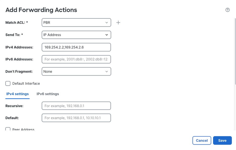
Secure FTD - Policy Based Routing
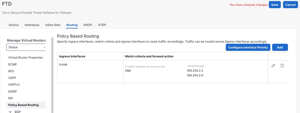
Secure FTD - Policy Based Routing
Configure BGP on FTD
1. Enable BGP
- Navigate to Devices > Device Management > FTD > Routing > General Settings > BGP
- Enable BGP and add the AS number ( FTD local AS number)
- Click Save
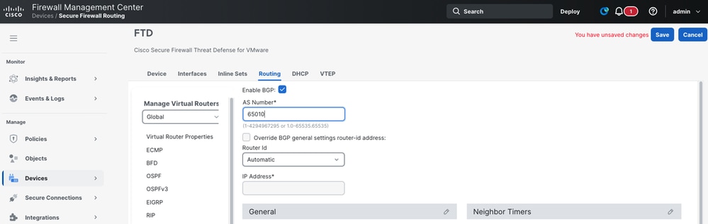
Secure FTD - BGP Routing
- Navigate to BGP > IPv4
2. Add BGP Neighbor - Secure Access BGP peers are 169.254.0.5 and. 169.254.0.9
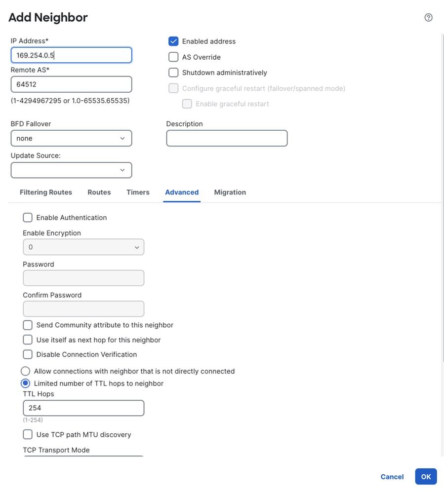
Secure FTD - BGP Routing
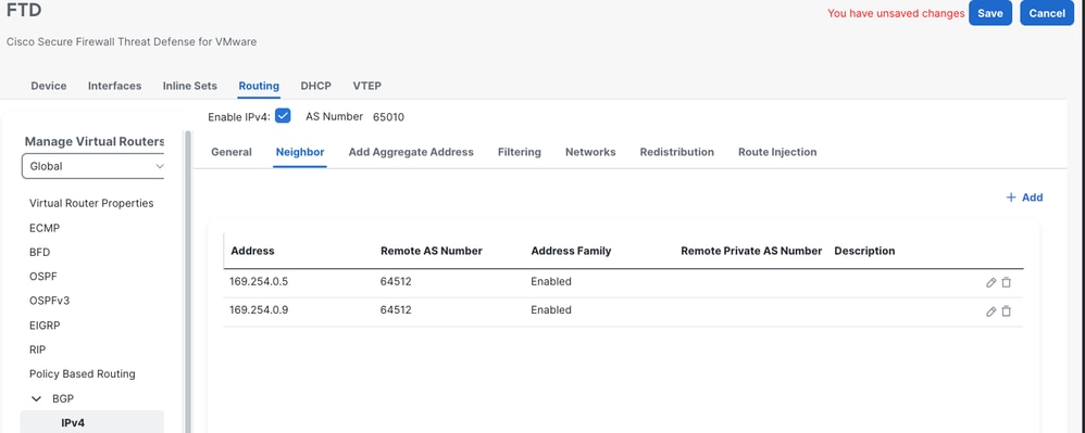
Secure FTD - BGP Routing
3. Add the Networks - Networks that needs to be advertised to Secure Access
- Click OK
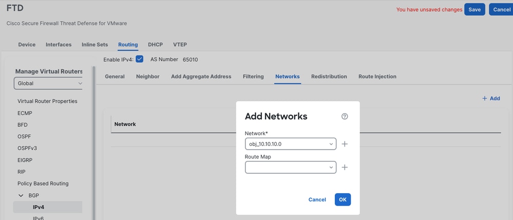
Secure FTD - BGP Routing
- Save and Deploy the changes
Verify Tunnel Status
On Secure Access
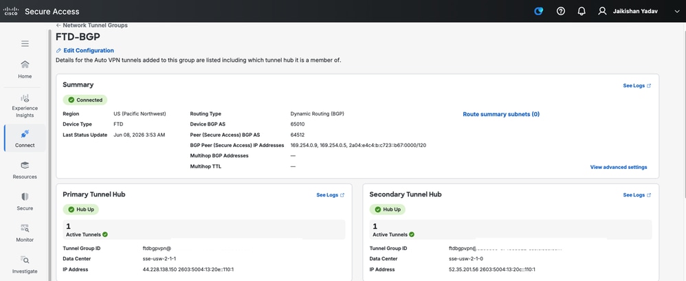
Secure FTD - IPsec Tunnel Status
On FMC
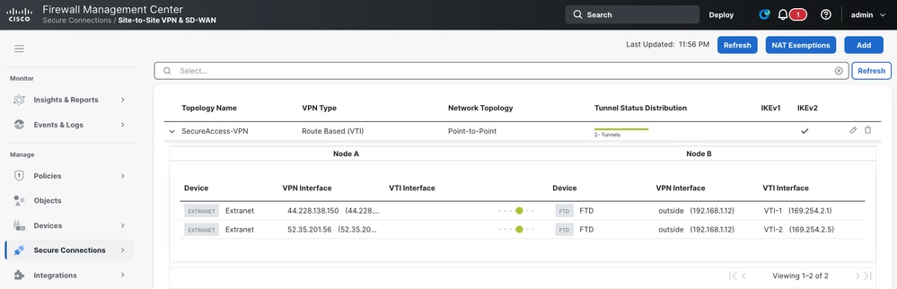
Secure FMC - IPsec Tunnel Status
Configure Static Route-based IPsec VPN on Adaptive Security Appliance (ASA) with PBR
VPN Configuration on Secure Access
1. Login to Secure Access dashboard Secure Access
2. Navigate to Connect > Network Connections > Network Tunnel Groups and click on +Add to configure the Network Tunnel Group
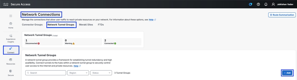
Secure Access - Network Tunnel Groups
3. Configure Network Tunnel Group - General Settings
- Configure Tunnel Group Name, Region and Device Type
- Click Next
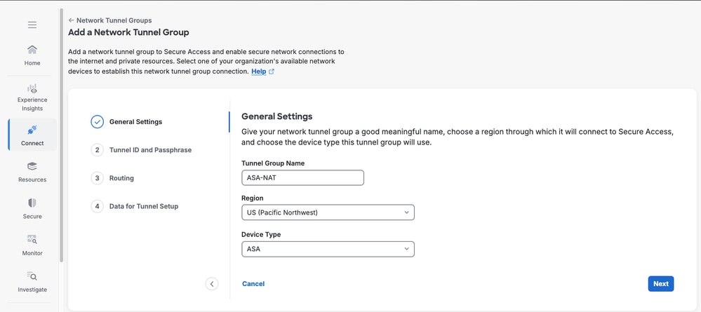
Secure Access - Network Tunnel Groups General Settings
4. Configure Tunnel ID and Passphrase.
- Configure the Tunnel ID and Passphrase.
- Click Next
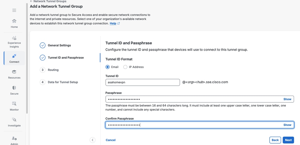
Secure Access - Network Tunnel Groups
5. Enable Network Address Translation (NAT)
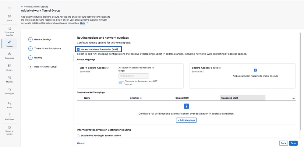
Secure Access - Network Tunnel Groups NAT Settings
6. Add Destination NAT Mapping
Flow 1 - Router 1 to Router 2 ( Site to Secure Access)
Flow 2 - Router 2 to Router 1 (Secure Access to Site)
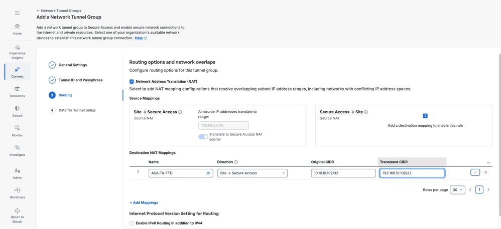
Secure Access - Network Tunnel Groups NAT Settings

Caution: When NAT is enabled, BGP is not possible. Also, configure static VPN on Customer Edge devices.

Tip: Always remember to ping a translated IP. Translated IP goes in Translated CIDR and Real IP goes in Original CIDR.
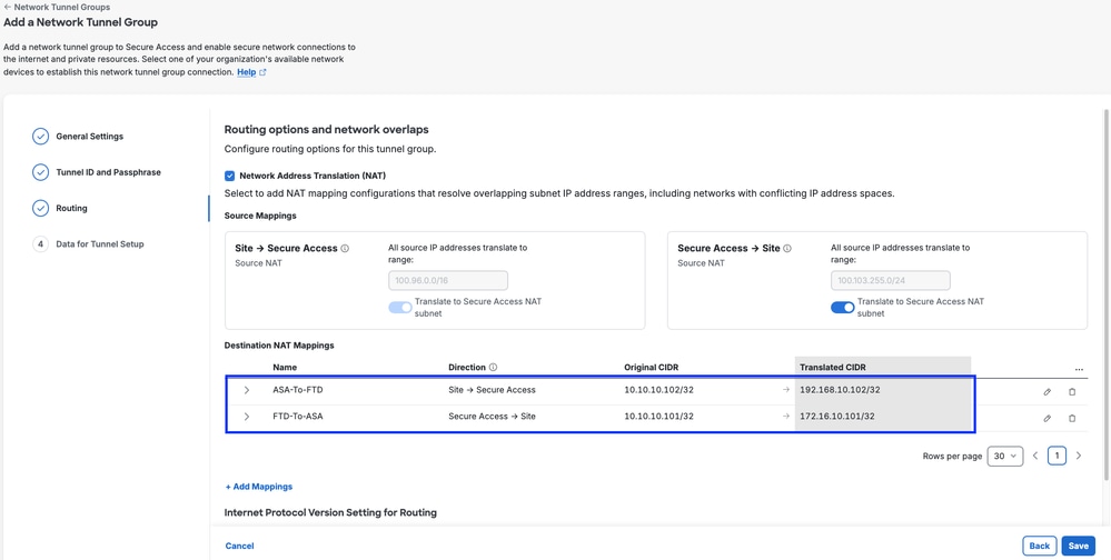
Secure Access - Network Tunnel Groups NAT Settings
Click Save
Tip: For traffic going from 'Site A' to 'Site B', from CNHE-1 point of view direction is 'Site-> SecureAccess'. For traffic going from 'site B' to 'site A', from CNHE-1 point of view direction is 'SecureAccess -> Site'
VPN Configuration on ASA
1. Log into ASA CLI, enter enable mode and verify basic IP connectivity towards the internet
ASA# sh ip
System IP Addresses:
Interface Name IP address Subnet mask Method
GigabitEthernet0/0 outside 192.168.1.40 255.255.255.0 manual
GigabitEthernet0/1 inside 10.10.10.1 255.255.255.0 manual
Current IP Addresses:
Interface Name IP address Subnet mask Method
GigabitEthernet0/0 outside 192.168.1.40 255.255.255.0 manual
GigabitEthernet0/1 inside 10.10.10.1 255.255.255.0 manual
ASA# ping 8.8.8.8
Type escape sequence to abort.
Sending 5, 100-byte ICMP Echos to 8.8.8.8, timeout is 2 seconds:
!!!!!
Success rate is 100 percent (5/5), round-trip min/avg/max = 20/28/30 ms
ASA#
2. Configure IKEv2 policy and enable IKEv2 on the outside interface
crypto ikev2 policy 10
encryption aes-gcm-256
integrity null
group 19
lifetime seconds 86400
crypto ikev2 enable outside
3. Configure IPSec proposal
crypto ipsec ikev2 ipsec-proposal Ipsec-Proposal-primary
protocol esp encryption aes-gcm-256
4. Configure IPsec profile
crypto ipsec profile csa-profile-primary
set ikev2 ipsec-proposal Ipsec-Proposal-primary
set ikev2 local-identity email-id <primary tunnel-id>
5. Configure Group Policy, and enable IKEv2 protocol under attribute.
group-policy csa-policy-primary internal
group-policy csa-policy-primary attributes
vpn-tunnel-protocol ikev2
6. Configure Tunnel Group.
tunnel-group 44.228.138.150 type ipsec-l2l
tunnel-group 44.228.138.150 general-attributes
default-group-policy csa-policy-primary
tunnel-group 44.228.138.150 ipsec-attributes
ikev2 remote-authentication pre-shared-key <pre-shared-key>
ikev2 local-authentication pre-shared-key <pre-shared-key>
7. Configure Virtual Tunnel Interface (VTI)
- Nameif can be if your choice
- IP address assigned to VTI must not overlap with any other interface on the ASA
- Tunnel source must be the outside interface of the firewall
- Tunnel destination must be the Data Center IP address
interface Tunnel1
nameif VTI-1
ip address 169.254.2.1 255.255.255.252
tunnel source interface outside
tunnel destination 44.228.138.150
tunnel mode ipsec ipv4
tunnel protection ipsec profile csa-profile-primary
8. Configure routing in way that, traffic to the mapped IP address or subnet is routed inside the VTI interface. Next hop needs to by IP within range of VTI.
route VTI-1 0.0.0.0 0.0.0.0 169.254.2.2 5. ( for internet based, RAVPN pool or CGNAT traffic
or
route VTI-1 172.16.10.101 255.255.255.255 169.254.2.2 5
Policy Based Routing
1. Access List
access-list PBR extended permit ip 10.10.10.0 255.255.255.0 any
2. Route-map
route-map RM-CSA permit 10
match ip address PBR
set ip next-hop 169.254.2.2 169.254.2.6
3. Apply Route-map on ingress interface
interface GigabitEthernet0/1
nameif inside
security-level 100
ip address 10.10.10.1 255.255.255.0
policy-route route-map RM-CSA
Verify
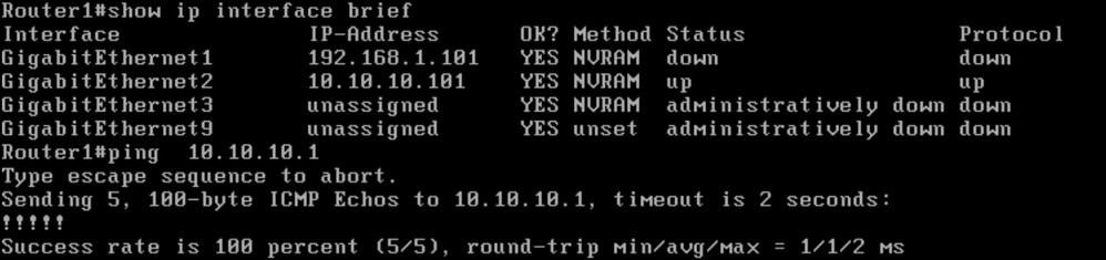
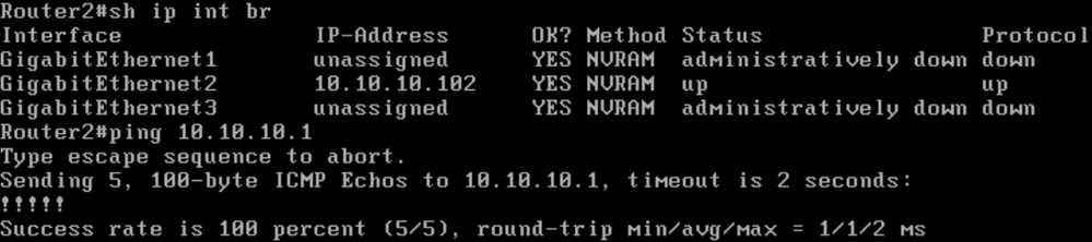
Router interface and GW reachability status
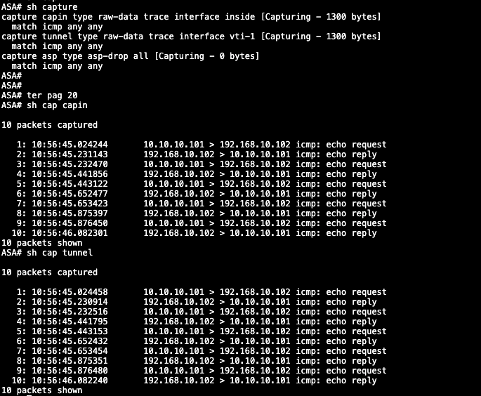
Test 1- Router2 --> Router1. - Ping Test

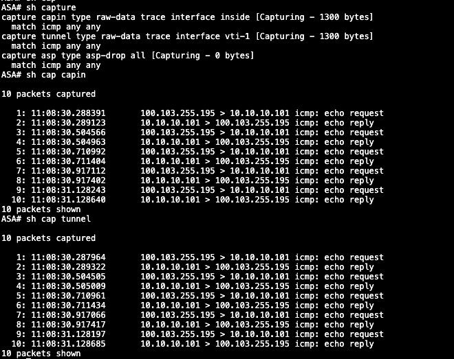
Packet capture on ASA (Local FW)
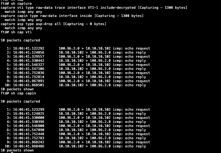
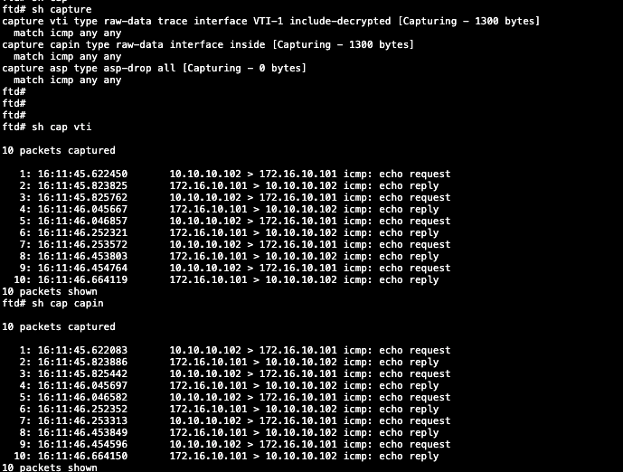
Packet Capture on FTD (Remote FW)
Test 2. - Router 2 ---> Router 1 ping test
FTD Packet Capture (Local FW)
ASA packet capture (Remote FW)
Revision History
| Revision | Publish Date | Comments |
|---|---|---|
1.0 |
29-Jul-2026
|
Initial Release |

 Feedback
Contact Cisco
- Open a Support Case

- (Requires a Cisco Service Contract)