Configure Ethernet Virtual Connections on Catalyst 8000 Routers
Available Languages
Contents
Introduction
This document describes practical examples to configure Ethernet Virtual Connections (EVC) on Catalyst 8000 Enterprise Platforms.
Prerequisites
Requirements
There are no specific requirements for this document.
Components Used
The information in this document is based on Cisco IOS® XE software version 17.
The information in this document was created from the devices in a specific lab environment. All of the devices used in this document started with a cleared (default) configuration. If your network is live, ensure that you understand the potential impact of any command.
Background Information
Ethernet Virtual Connections provide a flexible, standards-based framework for delivering Layer 2 services across a network by representing an end-to-end logical path between user network interfaces.
Central to this architecture is the service instance, which acts as a logical entity on a physical interface to classify incoming traffic based on specific criteria, such as VLAN tags, and map it to the appropriate network service. These service instances are associated with a bridge domain, which functions as a logical broadcast domain that facilitates Layer 2 switching or routing between these instances, effectively decoupling the service definition from the underlying physical infrastructure and allowing for granular control over traffic forwarding and policy application within the virtualized environment.
Configure
Network Diagram
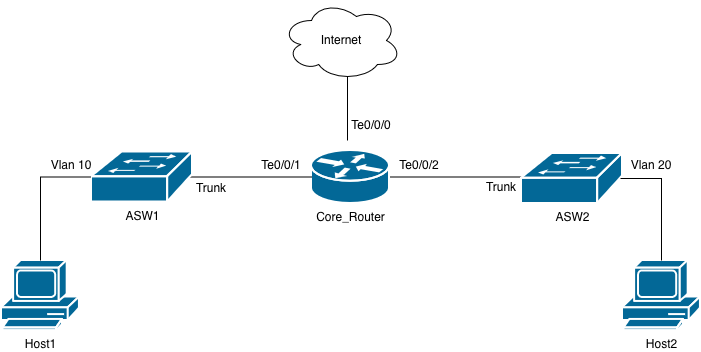 Topology Diagram
Configurations
Consider the topology diagram. You want to use the Core_Router as the default gateway for all hosts in the network. Host1 and Host2 are in the same VLANs, but they can also be in different VLANs.
If you use subinterfaces in the Core_Router, there are two main challenges:
- You have to configure different subnets for hosts that are part of the same VLAN, which forces you to use two different default gateways.
- Hosts within the same VLAN cannot communicate between them directly because each subinterface breaks a broadcast domain.
You can configure the Core_Router to bridge packets that do not need to be routed and, you can also configure a single interface to act as the default gateway for both hosts. This can be done with Ethernet Virtual Connections (EVC), and then map them to a Bridge Domain. The interface that acts as the default gateway is called Bridge Domain Interface (BDI).
For this specific example, the access Switches are already configured with the corresponding access VLANs and trunks allowing the same.
Example1. Bridge Packets Between Hosts in the Same VLAN
Core_Router#configure terminal
Core_Router(config)#interface TenGigabitEthernet 0/0/1
Core_Router(config-if)#service instance 10 ethernet
Core_Router(config-if-srv)#encapsulation dot1q 10
Core_Router(config-if-srv)#bridge-domain 10
Core_Router(config-if-srv)#exit
Core_Router(config-if)#exit
Core_Router(config)#
Core_Router(config)#interface TenGigabitEthernet 0/0/2
Core_Router(config-if)#service instance 10 ethernet
Core_Router(config-if-srv)#encapsulation dot1q 10
Core_Router(config-if-srv)#bridge-domain 10
Core_Router(config-if-srv)#exit
Core_Router(config-if)#exit
Core_Router(config)#
Core_Router(config)#bridge-domain 10
Core_Router(config)#end
Core_Router#

Note: The Service Instance ID does not have to be the same as the VLAN ID, which is specified by the encapsulation dot1q <vlan-id> command. It is a best practice to match them for identification and troubleshooting purposes.
Host1 and Host2 can now ping each other.
Example 2. Configure BDI to Act as the Default Gateway for Both Host 10 and Host 20
Core_Router#configure terminal
Core_Router(config)#interface bdi 10
Core_Router(config-if)#encapsulation dot1Q 10
Core_Router(config-if)#ip address 10.10.10.1 255.255.255.0
Core_Router(config-if)#no shutdown
Core_Router(config-if)#end
Core_Router#
You can now ping both hosts from the BDI.
Core_Router#ping 10.10.10.10
Type escape sequence to abort.
Sending 5, 100-byte ICMP Echos to 10.10.10.10, timeout is 2 seconds:
!!!!!
Success rate is 100 percent (5/5), round-trip min/avg/max = 1/1/2 ms

Core_Router#ping 10.10.10.20
Type escape sequence to abort.
Sending 5, 100-byte ICMP Echos to 10.10.10.20, timeout is 2 seconds:
!!!!!
Success rate is 100 percent (5/5), round-trip min/avg/max = 1/1/3 ms

Core_Router#show ip arp
Protocol Address Age (min) Hardware Addr Type Interface
Internet 10.10.10.1 - 001e.e525.2fbf ARPA BDI10
Internet 10.10.10.10 0 aabb.cc00.0f00 ARPA BDI10
Internet 10.10.10.20 0 aabb.cc00.1000 ARPA BDI10

Warning: Ensure to configure dot1q encapsulation in the BDI. By default, Bridge Domain Interfaces do not tag packets with VLAN IDs. If this configuration is not applied, the packet is placed in the native vlan when it arrives at the L2 Switch trunks.
Example 3. Configure Routing Through BDI Interfaces
Core_Router#configure terminal
Core_Router(config)#interface bdi 20
Core_Router(config-if)# encapsulation dot1Q 20
Core_Router(config-if)# ip address 10.20.20.1 255.255.255.0
Core_Router(config-if)#exit
Core_Router(config)#
Core_Router(config)#
Core_Router(config)#interface TenGigabitEthernet 0/0/2
Core_Router(config-if)#service instance 20 ethernet
Core_Router(config-if-srv)#encapsulation dot1q 20
Core_Router(config-if-srv)#bridge-domain 20
Core_Router(config-if-srv)#exit
Core_Router(config-if)#exit
Core_Router(config)#bridge-domain 20
Core_Router(config)#exit
Core_Router#
You can now ping Host 1 from BDI 20.
Core_Router#ping 10.10.10.10 source bdi 20
Type escape sequence to abort.
Sending 5, 100-byte ICMP Echos to 10.10.10.10, timeout is 2 seconds:
Packet sent with a source address of 10.20.20.1
!!!!!
Success rate is 100 percent (5/5), round-trip min/avg/max = 1/1/2 ms
Core_Router#
Example 4. The Rewrirte Option
You can configure Bridge Domain Interfaces without dot1q encapsulation; but, you must ensure that the L2 Switches receive the packets tagged with their corresponding VLAN ID. Similarly, you must ensure that the received packets are passed to the BDI without VLAN tags.
This is what the configuration looks like.
interface TenGigabitEthernet 0/0/1
no ip address
negotiation auto
service instance 10 ethernet
encapsulation dot1q 10
rewrite ingress tag pop 1 symmetric
bridge-domain 10
!

interface TenGigabitEthernet 0/0/2
no ip address
negotiation auto
service instance 20 ethernet
encapsulation dot1q 20
rewrite ingress tag pop 1 symmetric
bridge-domain 20
!
This is how rewrite works:
1. Packets are received from the L2 Switch with a VLAN tag.
2. The command enables the router to pop the outermost ingress VLAN tag.
3. Packets are placed within the corresponding Bridge Domain.
4. BDI receives the packet without a tag.
5. The opposite action happens for outgoing packets. This is because you configured the symmetric keyword at the end. This ensures packets get a VLAN tag pushed on egress, and the L2 Switches receive tagged packets.
Verify
To verify the configurations are correct, check to see the configuration of the physical interfaces where service instances are configured as well as BDIs.
Core_Router#show running-config interface tenGigabitEthernet 0/0/1
Building configuration...

Current configuration : 166 bytes
!
interface TenGigabitEthernet0/0/1
no ip address
speed 1000
no negotiation auto
service instance 10 ethernet
encapsulation dot1q 10 >>>>>>>>>>>>>>>> always check the dot1q tag is correct.
bridge-domain 10
!
end
Check to see ig the bridge-domain is mapped to the interfaces and that the service instances are correct.
Core_Router#show bridge-domain 10
Bridge-domain 10 (2 ports in all)
State: UP Mac learning: Enabled
Aging-Timer: 300 second(s)
Unknown Unicast Flooding Suppression: Disabled
Maximum address limit: 65536
TenGigabitEthernet0/0/1 service instance 10
TenGigabitEthernet0/0/2 service instance 20
AED MAC address Policy Tag Age Pseudoport
-----------------------------------------------------------------------------
Revision History
| Revision | Publish Date | Comments |
|---|---|---|
1.0 |
07-Jul-2026
|
Initial Release |

 Feedback
Contact Cisco
- Open a Support Case

- (Requires a Cisco Service Contract)