Troubleshoot Netflow on IOS XE
Available Languages
Contents
Introduction
This document describes how to troubleshoot Netflow on Technologies for Cisco IOS® XE.
Prerequisites
Requirements
Cisco recommends that you have knowledge of these topics:
- Netflow
- Cisco IOS XE
For more information on these topics, see:
Flexible Netflow Overview
Configuring Flexible NetFlow (Catalyst 9300 Switches)
Configuring Flexible NetFlow (Catalyst 9400 Switches)
Configuring Flexible NetFlow (Catalyst 9500 Switches)
Configuring Flexible NetFlow (Catalyst 9600 Switches)
Components Used
The information in this document is based on Cisco IOS XE software.
The information in this document was created from the devices in a specific lab environment. All of the devices used in this document started with a cleared (default) configuration. If your network is live, ensure that you understand the potential impact of any command.
Troubleshoot NetFlow on Cisco Routers
Network Diagram
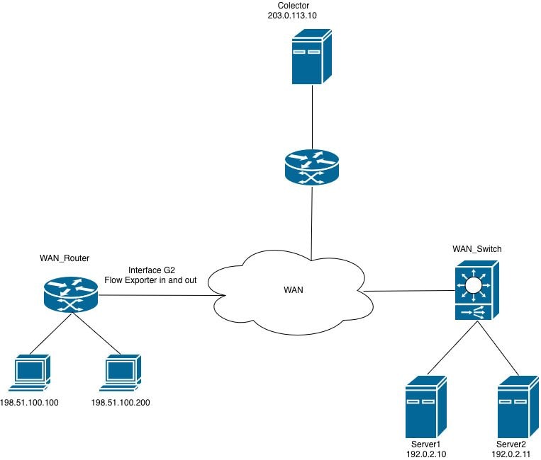 Netflow on Routers
Collector is not Receiving NetFlow Export Packets (CFLOWS) from the Router
The collector is not receiving the information from the router on the interface GigabitEthernet2.
Step 1. Verify Exporter Configuration.
- Collector IP address
- Source interface
- UDP port
- Export protocol (NetFlow v9/IPFIX)
WAN_Router#show running-config | section flow exporter
flow exporter Netflow_Exporter
destination 203.0.113.10
source Loopback0
transport udp 9996
template data timeout 60
Step 2. Verify Interface Status.
Confirm that GigabitEthernet2 is operational:
- Interface is up/up
- Correct IP address is configured
- No excessive errors or drops
WAN_Router#show interface gigabitEthernet 2 | include up|error|drop
GigabitEthernet2 is up, line protocol is up
Full Duplex, 1000Mbps, link type is auto, media type is Virtual
output flow-control is unsupported, input flow-control is unsupported
Input queue: 0/375/0/0 (size/max/drops/flushes); Total output drops: 0
0 input errors, 0 CRC, 0 frame, 0 overrun, 0 ignored
0 output errors, 0 collisions, 0 interface resets
0 unknown protocol drops
Step 3. Verify Reachability to the Collector.
Test connectivity from the source interface:
WAN_Router#ping 203.0.113.10 source Loopback 0
Type escape sequence to abort.
Sending 5, 100-byte ICMP Echos to 203.0.113.10, timeout is 2 seconds:
Packet sent with a source address of 198.51.100.10
!!!!!
Success rate is 100 percent (5/5), round-trip min/avg/max = 1/2/5 ms
WAN_Router#

WAN_Router#traceroute 203.0.113.10 source Loopback 0 numeric
Type escape sequence to abort.
Tracing the route to 203.0.113.10
VRF info: (vrf in name/id, vrf out name/id)
1 X.X.X.X 2 msec 1 msec 1 msec
2 Y.Y.Y.Y 2 msec 2 msec 1 msec
3 Z.Z.Z.Z 2 msec * 2 msec
WAN_Router#
Step 4. Verify Exporter Statistics.
Verify that the router is generating and transmitting NetFlow export packets to the configured collector address.
Verify:
- Successfully sent packets
- Successfully sent templates
- No transmission failures
- No socket errors
WAN_Router#show flow exporter statistics
Flow Exporter Netflow_Exporter:
Packet send statistics:
Successfully sent: 41 (3780 bytes)

Client send statistics:
Client: Flow Monitor MONITOR_INGRESS
Records added: 35
- sent: 35
Bytes added: 1750
- sent: 1750

Client: Flow Monitor MONITOR_EGRESS
Records added: 35
- sent: 35
Bytes added: 1750
- sent: 1750
Step 5. Verify Flow Creation.
Verify that flow entries are being populated and maintained in the flow monitor cache.
Verify:
- Active flows are present in the flow monitor cache.
- Cache entries are incrementing, which indicates that traffic is being recorded.
- Flow entries are expiring (aging out) within the expected timeout intervals.

Note: If no flows are observed in the cache, investigate the flow monitor and record configuration, as the issue is likely unrelated to the export function.
WAN_Router#show flow monitor MONITOR_EGRESS cache
Cache type: Normal (Platform cache)
Cache size: 200000
Current entries: 14
High Watermark: 27

Flows added: 3032
Flows aged: 3018
- Active timeout ( 60 secs) 200
- Inactive timeout ( 30 secs) 2818

IPV4 SOURCE ADDRESS: 198.51.100.200
IPV4 DESTINATION ADDRESS: 192.0.2.11
TRNS SOURCE PORT: 57188
TRNS DESTINATION PORT: 1967
INTERFACE OUTPUT: Gi2
IP TOS: 0x00
IP PROTOCOL: 17
counter bytes long: 80
counter packets long: 1
timestamp abs first: 22:09:34.067
timestamp abs last: 22:09:34.067
Based on the output, can be determined:
- The flow monitor MONITOR_EGRESS is operational and actively populating the cache with flow entries.
- Cache health is confirmed - entries are being added and removed (aged out) at expected rates.
- A significant portion of flows (2818 of 3018 aged) are expiring due to the inactive timeout, which is expected behavior for short-duration or low-frequency traffic.
- The displayed cache entry represents a single-packet UDP flow (protocol 17) from source 198.51.100.200, port 57188, to destination 192.0.2.11, port 1967, exiting via interface GigabitEthernet2.
Step 6. Verify Monitor Attachment.
Confirm that the flow monitor is applied to the correct interface.
WAN_Router#show running-config interface gigabitEthernet 2
Building configuration...

Current configuration : 217 bytes
!
interface GigabitEthernet2
ip flow monitor MONITOR_EGRESS output
ip address x.x.x.x 255.255.255.252
ip ospf network point-to-point
ip ospf 1 area 0
negotiation auto
end
Step 7. Verify ACLs or Security Policies.
Verify that no configured ACLs or security policies are filtering or dropping NetFlow export packets destined to the collector.:
WAN_Router#show running-config | include access-group
WAN_Router#
Step 8. Capture Traffic on the Router.
- Verify the routing path to the collector by issuing the show ip route <collector_IP> command. Identify the egress interface through which the router forwards NetFlow export traffic.
- Create an ACL that permits UDP packets with the source IP address matching the configured NetFlow exporter source interface and the destination IP address matching the collector. Apply this ACL to the packet capture to filter the relevant traffic.
WAN_Router#show running-config | sec flow exporter
flow exporter Netflow_Exporter
destination 203.0.113.10
source Loopback0
transport udp 9996
template data timeout 60
WAN_Router#show ip route 203.0.113.10
Routing entry for 203.0.113.10/32
Known via "ospf 1", distance 110, metric 22, type intra area
Last update from x.x.x.x on GigabitEthernet2, 02:12:27 ago
Routing Descriptor Blocks:
* x.x.x.x, from 203.0.113.10, 02:12:27 ago, via GigabitEthernet2
Route metric is 22, traffic share count is 1

WAN_Router#show running-config interface Loopback0
Building configuration...

Current configuration : 87 bytes
!
interface Loopback0
ip address 198.51.100.10 255.255.255.255
ip ospf 1 area 0
end

WAN_Router(config)#ip access-list extended netflow
WAN_Router(config-ext-nacl)#permit udp host 198.51.100.10 host 203.0.113.10
WAN_Router(config-ext-nacl)#end
!
WAN_Router#monitor capture netflow interface gigabitEthernet 2 out access-list netflow buffer size 10
WAN_Router#monitor capture netflow start
Started capture point : netflow

WAN_Router#show monitor capture netflow buffer brief
-------------------------------------------------------------------------------------
#    size     timestamp      source                destination     dscp   protocol
-------------------------------------------------------------------------------------
0    166      0.000000      198.51.100.10      -> 203.0.113.10      0 BE   UDP
1    166      0.055997      198.51.100.10      -> 203.0.113.10      0 BE   UDP
2    166      7.562019      198.51.100.10      -> 203.0.113.10      0 BE   UDP
3    166      7.617024      198.51.100.10      -> 203.0.113.10      0 BE   UDP
4    166      9.719009      198.51.100.10      -> 203.0.113.10      0 BE   UDP
5    166      9.776013      198.51.100.10      -> 203.0.113.10      0 BE   UDP
Note: The captured data can be stored on bootflash as a .pcap file or extracted as a hexadecimal dump in a text file, which can then be imported into a packet analysis tool such as Wireshark for detailed examination.
Configure and Capture Embedded Packet on Software
WAN_Router#show monitor capture netflow buffer dump
0
0000: AABBCC00 18005254 00B62209 08004500 ......RT.."...E.
0010: 009863EA 0000FF11 F121C633 640ACB00 ..c......!.3d...
0020: 710AC027 270C0084 F2E70009 0002086E q..''..........n
0030: 9B7A6A2F 2ED40000 07CE0000 01000102 .zj/............
0040: 0068C000 020BC633 64C80011 07AFDCA1 .h.....3d.......
0050: 00000002 00000000 00000034 00000000 ...........4....
0060: 00000001 0000019E C84E6CDC 0000019E .........Nl.....
0070: C84E6CDC C000020B C63364C8 0011007B .Nl......3d....{
0080: DCA10000 00020000 00000000 002C0000 .............,..
0090: 00000000 00010000 019EC84E 6CF00000 ...........Nl...
00A0: 019EC84E 6CF0 ...Nl.
Based on the packet capture analysis, the NetFlow export packets (cflows) are being transmitted from the router to the configured collector. Packet Capture Netflow
If the exporter statistics indicate successful transmissions but no packets are received at the collector, the issue likely resides in the network path between the router and the collector rather than in the NetFlow exporter configuration itself.
To isolate the issue, perform these verifications:
- Validate the network path - Review all ACLs applied along the path to ensure that the configured NetFlow UDP port is not being denied or filtered.
- Verify firewall policies - If a firewall exists in the path between the exporter and the collector, confirm that the applicable security policy permits the NetFlow export UDP traffic on the designated port.
- Confirm the collector application status - Verify that the collector service or process is running and actively listening on the expected UDP port.
NetFlow Exporter Fails to Transmit Flow Data to Collector in a VRF-Aware Topology
The collector does not receive flow export data from interface GigabitEthernet2. Although reachability to the collector has been verified, the flow records are not being delivered successfully.
Step 1. Verify Traffic is Being Learned.
Verify that the monitor is receiving traffic and creating flow entries.
WAN_Router#show flow monitor MONITOR_INGRESS cache
Cache type: Normal (Platform cache)
Cache size: 200000
Current entries: 7
High Watermark: 9

Flows added: 65
Flows aged: 58
- Active timeout ( 60 secs) 4
- Inactive timeout ( 30 secs) 54

IPV4 SOURCE ADDRESS: x.x.x.x
IPV4 DESTINATION ADDRESS: 224.0.0.5
TRNS SOURCE PORT: 0
TRNS DESTINATION PORT: 0
INTERFACE INPUT: Gi2
IP TOS: 0xC0
IP PROTOCOL: 89
counter bytes long: 100
counter packets long: 1
timestamp abs first: 01:54:53.144
timestamp abs last: 01:54:53.144
Step 2. Verify Export Statistics.
Check exporter operation.
WAN_Router#show flow exporter statistics
Flow Exporter Netflow_Exporter:
Packet send statistics :
Successfully sent: 0 (0 bytes)

Client send statistics:
Client: Flow Monitor MONITOR_INGRESS
Records added: 0
Bytes added: 0
The output indicates that the flow monitor MONITOR_INGRESS is successfully collecting and caching flow data; however, the flow exporter Netflow_Exporter is not transmitting any records to the collector.
Step 3. Verify Collector Reachability in the Routing Table.
Verify that a route to the collector IP address exists in the appropriate routing table. This can be the global routing table or a VRF-specific routing table, depending on the network topology.
WAN_Router#show ip route 203.0.113.10
% Network not in table

WAN_Router#show ip cef 203.0.113.10
0.0.0.0/0
no route
WAN_Router#show ip vrf
Name           Default RD         Interfaces
A             <not set>           Lo0
                                  Gi1
                                  Gi2

WAN_Router#show ip route vrf A 203.0.113.10

Routing Table: A
Routing entry for 203.0.113.10/32
Known via "ospf 1", distance 110, metric 22, type intra area
Last update from x.x.x.x on GigabitEthernet2, 00:37:34 ago
Routing Descriptor Blocks:
* x.x.x.x, from 203.0.113.10, 00:37:34 ago, via GigabitEthernet2
Route metric is 22, traffic share count is 1

WAN_Router#ping vrf A 203.0.113.10 source loopback0 <The source interface specified in the flow exporter configuration, which determines the IP address used to send export packets to the collector.
Type escape sequence to abort.
Sending 5, 100-byte ICMP Echos to 203.0.113.10, timeout is 2 seconds:
Packet sent with a source address of 198.51.100.10
!!!!!
Success rate is 100 percent (5/5), round-trip min/avg/max = 1/1/3 ms
WAN_Router
Step 4. Verify the flow exporter configuration.
Review the exporter configuration to confirm that the appropriate VRF is specified, ensuring the exporter is VRF-aware.
WAN_Router#show running-config | sec flow exporter
flow exporter Netflow_Exporter
destination 203.0.113.10
source Loopback0
transport udp 9996
template data timeout 60
WAN_Router#
The root cause of the export failure is the absence of a VRF definition in the flow exporter configuration. In a VRF-aware network, the flow exporter must be explicitly configured with the appropriate VRF to ensure that export packets are forwarded to the collector through the correct routing table.
The corrected configuration and the verification steps to confirm that the exporter is functioning as expected are shown here.
WAN_Router#show running-config | section flow exporter
flow exporter Netflow_Exporter
destination 203.0.113.10 vrf A
source Loopback0
transport udp 9996
template data timeout 60
Step 5. Verify That Export Packets Are Egressing the Router.
Enable packet captures on the egress interface and use the relevant show commands to confirm that NetFlow export packets are being sent to the collector.
WAN_Router#show monitor capture netflow parameter
monitor capture netflow interface GigabitEthernet2 OUT
monitor capture netflow access-list netflow
monitor capture netflow buffer size 10
monitor capture netflow limit pps 1000
WAN_Router#show flow exporter statistics
Flow Exporter Netflow_Exporter:
Packet send statistics :
Successfully sent: 7 (576 bytes)

Client send statistics:
Client: Flow Monitor MONITOR_INGRESS
Records added: 9
- sent: 9
Bytes added: 450
- sent: 450

WAN_Router#show monitor capture netflow buffer brief
--------------------------------------------------------------------------------
#   size   timestamp      source               destination      dscp    protocol
--------------------------------------------------------------------------------
0    114    0.000000     198.51.100.10     -> 203.0.113.10         0 BE UDP
1    118    31.873947    198.51.100.10     -> 203.0.113.10         0 BE UDP
2    166    32.955004    198.51.100.10     -> 203.0.113.10         0 BE UDP
3    166    43.580963    198.51.100.10     -> 203.0.113.10         0 BE UDP
4    166    53.061993    198.51.100.10     -> 203.0.113.10         0 BE UDP
5    114    62.480978    198.51.100.10     -> 203.0.113.10         0 BE UDP
Troubleshoot NetFlow on Cisco Switches
Network Diagram
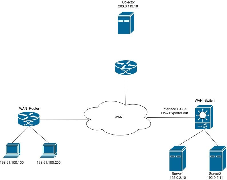 Netflow on Switches
Flow Monitor Cannot be Applied to the Interface
When attempting to attach the Flexible NetFlow (FNF) flow monitor to the interface in the egress direction, the router rejects the configuration and generates an error message.
WAN_Switch(config-if)#interface TwentyFiveGigE1/0/1
WAN_Switch(config-if)#ip flow monitor MONITOR_INGRESS input
% Flow Monitor: Failed to add monitor to interface: Invalid set of fields in monitor record for wired interface
Step 1. Verify the monitor configuration.
WAN_Switch#show running-config | section flow monitor
flow monitor MONITOR_INGRESS
exporter Netflow_Exporter
cache timeout inactive 30
cache timeout active 60
record INGRESS
Step 2. Review the flow record configuration for direction-specific fields. The most common field that causes this issue is: match application name.
WAN_Switch#show running-config | section flow record
flow record INGRESS
match ipv4 version
match ipv4 protocol
match application name
match ipv4 destination address
match ipv4 source address
match transport destination-port
match transport source-port
match interface input
match flow direction
collect timestamp absolute first
collect timestamp absolute last
collect counter bytes long
collect counter packets long
The match application name field in a Flexible NetFlow (FNF) flow record is used within Application Visibility and Control (AVC) deployments to identify and classify traffic based on the application generating the flow.
This field leverages the Network-Based Application Recognition (NBAR) engine to perform deep packet inspection (DPI) and identify the application associated with each flow. Rather than relying solely on port numbers or IP addresses, this field enables the router to classify traffic at the application layer (Layer 7).
In a deployment that uses only Flexible NetFlow (FNF) without the AVC feature enabled, this field is incompatible with the interface configuration and prevents the flow monitor from being attached to the monitored interface.
Note: On the Catalyst 9500H and Catalyst 9600 platforms, the AVC feature is not available. For AVC-based flow monitoring, the Catalyst 9300 series is the supported platform.
3. Remove the unsupported field from the flow record configuration, then reapply the flow monitor to the interface.
WAN_Switch(config)#interface twentyFiveGigE 1/0/1
WAN_Switch(config-if)#no ip flow monitor MONITOR_INGRESS in
WAN_Switch(config)#no flow monitor MONITOR_INGRESS
WAN_Switch(config)#flow record INGRESS
WAN_Switch(config-flow-record)#no match flow direction
<snip>
Note: After modifying the flow record, reapply the flow monitor configuration and attach the flow monitor to the interface to complete the configuration change.
Step 4. Confirm that the flow monitor is operational after the configuration changes have been applied.
WAN_Switch#show flow monitor MONITOR_INGRESS statistics
Cache type: Normal (Platform cache)
Cache size: 10000
Current entries: 1

Flows added: 1
Flows aged: 0

WAN_Switch#show flow monitor MONITOR_INGRESS cache
Cache type: Normal (Platform cache)
Cache size: 10000
Current entries: 1

Flows added: 1
Flows aged: 0

IPV4 SOURCE ADDRESS: x.x.x.x
IPV4 DESTINATION ADDRESS: y.y.y.y
TRNS SOURCE PORT: 0
TRNS DESTINATION PORT: 0
INTERFACE INPUT: Twe1/0/1
FLOW DIRECTION: Input
IP VERSION: 4
IP PROTOCOL: 89
counter bytes long: 708
counter packets long: 7
timestamp abs first: 20:38:23.408
timestamp abs last: 20:39:12.408
Revision History
| Revision | Publish Date | Comments |
|---|---|---|
1.0 |
18-Jun-2026
|
Initial Release |
 Feedback