Configure VRF Label Mode with Carrier Supporting Carrier
Available Languages
Download Options
Bias-Free Language
The documentation set for this product strives to use bias-free language. For the purposes of this documentation set, bias-free is defined as language that does not imply discrimination based on age, disability, gender, racial identity, ethnic identity, sexual orientation, socioeconomic status, and intersectionality. Exceptions may be present in the documentation due to language that is hardcoded in the user interfaces of the product software, language used based on RFP documentation, or language that is used by a referenced third-party product. Learn more about how Cisco is using Inclusive Language.
Contents
Introduction
This document describes why the Per-Virtual Routing and Forwarding (VRF) or Per-Customer Equipment (CE) Label mode is not supported with Carrier Supporting Carrier (CSC) scenario. Also, how the forwarding plane behaves when you migrate a CSC customer from Per-Prefix to any other VRF Label mode.
Prerequisites
Requirements
There are no specific requirements for this document.
Components Used
This document is not restricted to specific software and hardware versions.
The information in this document was created from the devices in a specific lab environment. All of the devices used in this document started with a cleared (default) configuration. If your network is live, make sure that you understand the potential impact of any command.
Background Information
BGP Layer 3 VPNs generally support these MPLS Label Allocation modes on the PE:
Per-Prefix: By default, all learned routes from CE use per-prefix mode. A VPN label is generated per each VPNv4 prefix.
Per-CE mode allocates one VPN label for each BGP next-hop (i.e. CE router Per-VRF mode allocates one VPN label for each VRF. By default all connected interfaces and redistributed on PE will use a per-vrf aggregate label (includes: connected, redistributed, static to null0 and BGP aggregates).
| Per-Prefix | Per-CE | Per-VRF | |
| Label Allocation | One Label per prefix(default) | One Label per-ce | One Label per VRF |
| Label Savings | NIL | moderate | maximum |
| Description | Allocate separate MPLS service label for each prefix | Allocate one service Label for all prefix learned from one CE | Allocate one service Label for all prefix learned in a VRF |
This document is to provide guidance around which Label allocation method can be used in the CSC scenario.
Carrier supporting carriers (CSC) is implemented in circumstances in which one service provider needs to use the transport services provided by another service provider. The service provider providing the transport is called the backbone carrier and the service provider using the services provided by the backbone carrier is called a customer carrier. The customer carrier can either be an ISP provider or an MPLS VPN service provider.
In the CSC model, the links between the backbone and customer carrier are MPLS enabled to provide an end-to-end LSP path between the two POP sites located in the customer carrier network. In the CSC model, the backbone carrier providing MPLS VPN services to the customer carrier has knowledge of only the customer carrier's internal routes. These routes are relevant for building the LSP path between the two POP sites and for forming the iBGP or MP-iBGP session between the POP sites. User networks will then be transported across this iBGP or MP-iBGP session.
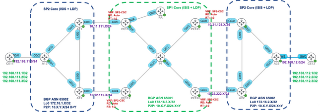
For example, in the given diagram - SP1 acts as a Backbone carrier and SP2 acts as a Customer carrier.
Label Exchange Methods in CSC Architecture: There are two ways of exchanging IGP labels in a CSC based MPLS VPN network:
- Using IGP for label exchange (TDP/LDP)
- Using BGP for label exchange (eBGP LU)
BGP has been used for label exchange in this example.
Configure
Network Diagram
Configurations
Initially, the default VRF label Mode (per-prefix) is used at PE111, PE112, PE121 & PE122.
|
PE111 |
PE112 |
|
interface GigabitEthernet0/0/0/0 vrf SP2-CSC ipv4 address 10.11.111.111255.255.255.0 ! router static vrf SP2-CSC address-family ipv4 unicast 10.11.111.11/32 GigabitEthernet0/0/0/0 ! ! router isis IGP is-type level-2-only net 49.0001.0000.0000.0111.00 address-family ipv4 unicast metric-style wide advertise passive-only mpls traffic-eng level-2-only mpls traffic-eng router-id Loopback0 ! interface Loopback0 passive address-family ipv4 unicast ! ! interface GigabitEthernet0/0/0/4 point-to-point address-family ipv4 unicast fast-reroute per-prefix fast-reroute per-prefix remote-lfa tunnel mpls-ldp ! ! interface GigabitEthernet0/0/0/5 point-to-point address-family ipv4 unicast fast-reroute per-prefix fast-reroute per-prefix remote-lfa tunnel mpls-ldp ! ! ! router bgp 65001 vrf SP2-CSC rd auto address-family ipv4 unicast redistribute connected allocate-label all ! neighbor 10.11.111.11 remote-as 65002 description SP2 address-family ipv4 labeled-unicast route-policy PASS in route-policy PASS out as-override ! ! ! |
interface GigabitEthernet0/0/0/4 vrf SP2-CSC ipv4 address 10.12.112.112 255.255.255.0 ! router static vrf SP2-CSC address-family ipv4 unicast 10.12.112.12/32 GigabitEthernet0/0/0/4 ! ! router isis IGP is-type level-2-only net 49.0001.0000.0000.0112.00 address-family ipv4 unicast metric-style wide advertise passive-only mpls traffic-eng level-2-only mpls traffic-eng router-id Loopback0 ! interface Loopback0 passive address-family ipv4 unicast ! ! interface GigabitEthernet0/0/0/5 point-to-point address-family ipv4 unicast fast-reroute per-prefix fast-reroute per-prefix remote-lfa tunnel mpls-ldp ! ! ! ! ! ! ! ! ! ! router bgp 65001 vrf SP2-CSC rd auto address-family ipv4 unicast redistribute connected allocate-label all ! neighbor 10.12.112.12 remote-as 65002 description SP2 address-family ipv4 labeled-unicast route-policy PASS in route-policy PASS out as-override ! ! ! |
Verify
Use this section in order to confirm that your configuration works properly.
By default, the PE router allocates separate local labels for each prefix (per-prefix label mode) learned from the eBGP neighbor. It is shown in these output captures.
RP/0/0/CPU0:PE111#show bgp vpnv4 unicast vrf SP2-CSC 172.16.1.11/32 | i Local Label
Local Label: 24006
RP/0/0/CPU0:PE111#show bgp vpnv4 unicast vrf SP2-CSC 172.16.1.12/32 | i Local Label
Local Label: 24014
RP/0/0/CPU0:PE111#show bgp vpnv4 unicast vrf SP2-CSC 172.16.1.13/32 | i Local Label
Local Label: 24007
LFIB table operation for respective Local Label is SWAP (with Outgoing Label) and send the packet towards Outgoing interface Gi0/0/0/0 (towards eBGP neighbor).
RP/0/0/CPU0:PE111#show mpls forwarding labels 24006
Local Outgoing Prefix Outgoing Next Hop Bytes
Label Label or ID Interface Switched
------ ----------- ------------------ ------------ --------------- ------------
24006 Pop 172.16.1.11/32[V] Gi0/0/0/0 10.11.111.11 0
Similar results can be verified at other PE routers (PE112, PE121, PE122) for the BGP LU routes learned from eBGP neighbor.
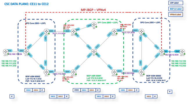
Trace results from CE11 to CE12
CE11#traceroute 192.168.112.1 source lo0 numeric
Type escape sequence to abort.
Tracing the route to 192.168.112.1
VRF info: (vrf in name/id, vrf out name/id)
1 192.168.11.13 2 msec 1 msec 2 msec
2 10.12.13.12 [MPLS: Labels 24010/24012 Exp 0] 36 msec 47 msec 36 msec
3 10.12.112.112 [MPLS: Labels 24013/24012 Exp 0] 39 msec 36 msec 39 msec
4 10.1.112.1 [MPLS: Labels 24003/24011/24012 Exp 0] 43 msec 43 msec 38 msec
5 10.1.121.121 [MPLS: Labels 24011/24012 Exp 0] 39 msec 39 msec 37 msec
6 10.21.121.21 [MPLS: Labels 24001/24012 Exp 0] 36 msec 34 msec 36 msec
7 10.21.23.23 [MPLS: Label 24012 Exp 0] 36 msec 37 msec 38 msec
8 192.168.12.12 [AS 65012] 36 msec * 39 msec
Respective label stack during dataplane forwarding is shown in this image:
Label Mode Per-VRF
After you change to Label Mode to per-vrf at PE111, PE112, PE121 & PE122.
PE1XX:
RP/0/0/CPU0:PE111(config)#router bgp 65001
RP/0/0/CPU0:PE111(config-bgp)#vrf SP2-CSC
RP/0/0/CPU0:PE111(config-bgp-vrf)#address-family ipv4 unicast
RP/0/0/CPU0:PE111(config-bgp-vrf-af)#label mode per-vrf
RP/0/0/CPU0:PE111(config-bgp-vrf-af)#root
RP/0/0/CPU0:PE111(config)#show
Tue Jan 25 13:45:43.444 UTC
Building configuration...
router bgp 65001
 vrf SP2-CSC
  address-family ipv4 unicast
   label mode per-vrf
  !
 !
!
end
RP/0/0/CPU0:PE111(config)#commit
Now, each PE router will allocate the same MPLS label for all originating vpnv4 prefixes (per-vrf label mode). It is shown in these output captures.
For example, PE111 originates.
RP/0/0/CPU0:PE111#sh bgp vpnv4 unicast vrf SP2-CSC 172.16.1.11/32 | i Local Label
Local Label: 24003
RP/0/0/CPU0:PE111#sh bgp vpnv4 unicast vrf SP2-CSC 172.16.1.12/32 | i Local Label
Local Label: 24003
RP/0/0/CPU0:PE111#sh bgp vpnv4 unicast vrf SP2-CSC 172.16.1.13/32 | i Local Label
Local Label: 24003
MPLS Forwarding Plane
LFIB table operation for respective Local Label is "Aggregate" (Outgoing Label), which means Untag and do a FIB lookup for it to find out the outgoing interface.
RP/0/0/CPU0:PE111#sh mpls forwarding labels 24003
Local  Outgoing    Prefix             Outgoing     Next Hop        Bytes
Label  Label       or ID              Interface                    Switched
------ ----------- ------------------ ------------ --------------- ------------
24003  Aggregate   SP2-CSC: Per-VRF   Aggr[V] \
                                      SP2-CSC                      8798

Let us try to Ping from CE11 to CE21

CE11#ping 192.168.112.1 source lo0
Type escape sequence to abort.
Sending 5, 100-byte ICMP Echos to 192.168.112.1, timeout is 2 seconds:
Packet sent with a source address of 192.168.111.1
.....
Success rate is 0 percent (0/5))
Wireshark Capture at PE121 (Gi0/0/0/5)
ICMP Echo (ping) request packets are received but no response is found.
Source IP: 192.168.111.1,
Destination IP: 192.168.112.1
Top Label: 24006
Bottom Label: 24012
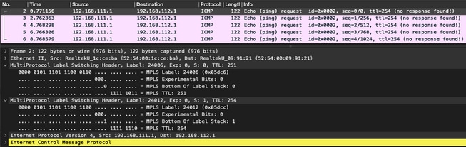
Since the LFIB operation is Aggregate which means Convert the incoming MPLS packet to an IP packet and then do a FIB lookup for it to find out the outgoing interface. So for the previously mentioned ICMP request packets, PE121 will remove all the labels and try to do the FIB lookup in "VRF: SP2-CSC" for 192.168.112.1/32. It will not find any CEF entry, so it will simply drop the packet.
That’s why label mode per-vrf is not supported for the CSC scenario.
Label Mode Per-CE
After you change to Label Mode to per-ce at PE111, PE112, PE121 & PE122.
PE1XX:
RP/0/0/CPU0:PE111(config)#router bgp 65001
RP/0/0/CPU0:PE111(config-bgp)#vrf SP2-CSC
RP/0/0/CPU0:PE111(config-bgp-vrf)#address-family ipv4 unicast
RP/0/0/CPU0:PE111(config-bgp-vrf-af)#label mode per-ce
RP/0/0/CPU0:PE111(config-bgp-vrf-af)#root
RP/0/0/CPU0:PE111(config)#show
Building configuration...
router bgp 65001
 vrf SP2-CSC
  address-family ipv4 unicast
   label mode per-ce
  !
 !
!
end
RP/0/0/CPU0:PE111(config)#commit

Rest of the routers will be configured similarly
Now, each PE router will allocate one MPLS label per Next-Hop (so per connected CE neighborship). It is shown in these output captures.
e.g. PE111 originates these prefixes and allocated same label - 24006

RP/0/0/CPU0:PE111#sh bgp vpnv4 unicast vrf SP2-CSC 172.16.1.11/32 | i Local Label
Local Label: 24006
RP/0/0/CPU0:PE111#sh bgp vpnv4 unicast vrf SP2-CSC 172.16.1.12/32 | i Local Label
Local Label: 24006
RP/0/0/CPU0:PE111#sh bgp vpnv4 unicast vrf SP2-CSC 172.16.1.13/32 | i Local Label
Local Label: 24006
MPLS Forwarding Plane
There is no LFIB entry for Local label 24006.
RP/0/0/CPU0:PE111#sh mpls forwarding labels 24006
RP/0/0/CPU0:PE111#

Let us try to Ping from CE11 to CE12

CE11#ping 192.168.112.1 source lo0
Type escape sequence to abort.
Sending 5, 100-byte ICMP Echos to 192.168.112.1, timeout is 2 seconds:
Packet sent with a source address of 192.168.111.1
.....
Success rate is 0 percent (0/5)
Wireshark Capture at PE121 (Gi0/0/0/5)
ICMP Echo (ping) request packets are received but no response is found.
Source IP: 192.168.111.1,
Destination IP: 192.168.112.1
Top Label: 24009
Bottom Label: 24012
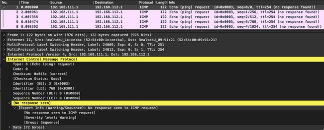
Enable debugging MPLS drop on PE121 and you can see that ICMP packets are dropped at PE121 due to no LFIB entry available.
RP/0/0/CPU0:PE121#debug mpls drop

RP/0/0/CPU0:PE121#show logging | i 24009
RP/0/0/CPU0:Jan 25 16:13:59.016 : netio[314]: ~mpls_netio_switch.c:2795~ Pkt Drop: GigabitEthernet0_0_0_5, No LFIB entry found for in_label 24009
RP/0/0/CPU0:Jan 25 16:14:01.016 : netio[314]: ~mpls_netio_switch.c:2795~ Pkt Drop: GigabitEthernet0_0_0_5, No LFIB entry found for in_label 24009
RP/0/0/CPU0:Jan 25 16:14:03.026 : netio[314]: ~mpls_netio_switch.c:2795~ Pkt Drop: GigabitEthernet0_0_0_5, No LFIB entry found for in_label 24009
RP/0/0/CPU0:Jan 25 16:14:05.016 : netio[314]: ~mpls_netio_switch.c:2795~ Pkt Drop: GigabitEthernet0_0_0_5, No LFIB entry found for in_label 24009
RP/0/0/CPU0:Jan 25 16:14:07.015 : netio[314]: ~mpls_netio_switch.c:2795~ Pkt Drop: GigabitEthernet0_0_0_5, No LFIB entry found for in_label 24009
This is how the label mode per-ce is not supported for the CSC scenario.
Troubleshoot
There is currently no specific troubleshooting information available for this configuration.
Conclusion
Hence concluded, you cannot use Per-VRF or Per-CE VRF Label mode for a CSC customer. Per-prefix is the only VRF Label mode that is supported for a CSC customer.
Related Information
Revision History
| Revision | Publish Date | Comments |
|---|---|---|
1.0 |
08-Feb-2022
|
Initial Release |
Contributed by Cisco Engineers
- Gaurav SinglaCisco Advanced Services
 Feedback
Contact Cisco
- Open a Support Case

- (Requires a Cisco Service Contract)