
Introduction
Cisco IQTM provides customers with features designed to improve asset visibility and deliver smarter insights across their environments. In addition, AI features such as the AI Assistant optimize operational outcomes and the Cisco IQ user experience by providing contextual understanding that empowers users to make proactive, informed decisions, and streamlines processes for customer engagement and success.
Cisco IQ On-Prem Air-Gapped is the deployment mode of Cisco IQ built for environments that cannot connect to the cloud. It is delivered as a self-contained Virtual Machine (VM), referred to as the Cisco IQ Virtual Appliance (VA), which runs entirely on the customer's premises in complete isolation from external networks, with software updates and maintenance packages obtained from Cisco IQ SaaS and transferred to the VA through an approved, manual process.
For organizations operating in regulated, high-security, and sovereign environments, VA removes the trade-off between insight and control. Customers deploy Cisco IQ Assets and Assessments capabilities inside their own network and retain complete ownership of their data, while still getting the insights and recommendations they expect from Cisco IQ. The Air-Gapped deployment mode extends the capabilities of Cisco IQ SaaS to isolated environments, enabling mission-critical teams to operate with the speed and diagnostic intelligence of cloud-connected enterprises.
This guide provides instructions for configuring and deploying the VA, including the process of setting up the required network environment.
Prerequisites
Ensure the following prerequisites are met before configuring and installing Cisco IQ VA.
Hardware and VM Resource Requirements
Cisco IQ VA is tested for multiple scale capacity and offers multiple deployment sizes to support your environment’s scaling needs. Refer to the table below to select the appropriate resource configuration based on your planned device discovery count for both Non-Graphics Processing Unit (GPU) and GPU-based deployment options.
Table 1: Hardware and VM Resource Requirements
| Resource |
Up to 5K Devices (Non-GPU Based) |
Up to 20K Devices (Non-GPU Based) |
Up to 20K Devices (GPU-Based)* |
| vCPU |
48 |
64 |
128 |
| RAM |
96GB |
128GB |
256GB |
| Storage (SSD) (Recommended for better performance) |
1.3TB |
1.3TB |
2.6TB |
| Collection Schedule |
24 hours or more |
24 hours or more |
24 hours or more |
| Supported Hypervisors |
● VMware ESXi v8.0 or later with VMware vSphere Web Client v8.0 or later ● Hyper-V on Microsoft Server 2022 and 2025 ● Kernel-based Virtual Machine (KVM) Hypervisor on RHEL v9.7 or later |
||
| Additional Recommendation |
● Cisco recommends that you use thick provisioning. While it is possible to use thin provisioning, over-provisioning can lead to a lack of storage capacity which can then result in degradation and loss of service. ● It is highly recommended to place appliance disks on a volume backed by SSDs. ● Disk write speed must be greater than 70 megabytes per second. |
||
*vCPU, RAM, and Disk resources are required to be equally divided between two (2) VMs.
AI Feature Resource Requirements
Cisco IQ VA is tested and supported on the NVIDIA RTX Pro 6000 Blackwell Server Edition GPU. This GPU configuration meets the performance and latency requirements at the planned deployment scale.
Table 2: AI Feature Resource Requirements
| Resource |
Recommended |
| Validated GPU |
NVIDIA RTX Pro 6000 Blackwell Server Edition |
| Additional GPU Options (Not validated) |
NVIDIA H200 (141 GB) |
| Additional GPU Options (Not validated, suggested with one (1) concurrent user) |
● NVIDIA H100 (80 GB) ● NVIDIA H100 NVL (94 GB) ● NVIDIA A100 (80 GB) |

Note: GPUs other than NVIDIA RTX Pro 6000 Blackwell Server Edition have not been validated in Cisco labs at the supported scale. Performance and latency are not guaranteed for non-validated GPUs. Please validate all non-supported hardware against your projected workload in a pre-production environment prior to production deployment.
Network Requirements
VA supports a single network interface.
IP Address and Hostname Requirements
The following IP address and hostname requirements must be met:
- Domain Name System (DNS): DNS simplifies system management by replacing numeric IP addresses with consistent, human-readable hostnames. This approach facilitates easier maintenance, seamless service integration, and reliable certificate validation in secure environments. Ensure that the IPv4 address is configured in your DNS with the following:
- A Record: Maps the hostname to the IPv4 address
- Associated Pointer (PTR) record: Required to support reverse DNS lookups; if an IP address resolves to multiple hostnames, the first resolved hostname is used to access the UI
- IP Addresses: The VA requires the following three (3) IP addresses to be configured before deployment:
- VM Access IP: A routable IPv4 address used to access the VA; no subnet restrictions apply, provided the address has network connectivity
- System Orchestration (SysOrch) IP: An internal /32 address used for communication between pods and the VM (the default is 192.168.23.17/32); this does not need to be changed unless the address conflicts with an existing address in your network
- Kubernetes Pod CIDR: An internal /20 subnet used for Kubernetes pod networking (the default is 100.64.0.0/20); this must not overlap with the SysOrch IP, DNS server, VM access IP, or NTP server addresses
Note: DHCP is currently not supported.
Port Requirements
The following table outlines the network ports required for Cisco IQ VA communication.
Table 3: Port Requirements
| Port(s) |
Protocol |
Description |
| 22 |
TCP |
Used for Administrator CLI and Cisco Support debugging sessions |
| 443 |
TCP |
Used for communication between Cisco IQ On-Prem and web browsers, as well as endpoint targets |
| 53, 123, 161 |
UDP |
Used to send and receive DNS, NTP, and SNMP traffic |
Supported Browsers
You must use the latest stable release of the following browsers to install and launch VA:
- Google Chrome
- Microsoft Edge
- Apple Safari
- Mozilla Firefox
Note: Support is limited to current browser versions, and older versions may not provide full functionality or may be unsupported as new updates are released.
Deployment Options
Cisco IQ VA offers two (2) flexible deployment options designed to meet your specific operational and security requirements. You can choose the deployment path that best aligns with your operational and security requirements, ensuring a scalable and future-ready solution.
Non-GPU Deployment (Non-AI Features)
The Non-GPU deployment runs on standard compute resources, with no GPU required, allowing you to access all core Cisco IQ, non-AI capabilities, including Assets and Inventory, Assessments, and day-to-day operations.
This option is ideal for environments where GPU hardware is not immediately available, allowing you to deploy the Cisco IQ VA and scale to AI features later.
The following high-level steps outline the non-GPU deployment process:
- System Planning: Determine the number of VMs required based on your scale and module needs. One (1) VM is required at minimum. See the table in Hardware and VM Resource Requirements for more details about Cisco IQ VA’s multi-scale capability.
- Resource Provisioning: Obtain the necessary IP addresses and VM resource. See Network Requirements for more details.
- Software Download:
- Download Cisco IQ VA Installer. See Downloading a VA for more details.
- Download required Cisco IQ Module Installer. See Modules and Rules Installation for more details.
- Deployment and Installation:
- Deploy the Cisco IQ VA. See Deploying VA on Hypervisor and Installing VA for Air-Gapped Mode for more details.
- Install the downloaded modules via the Package Catalog in the UI. See Modules and Rules Installation for more details.
Once these steps are complete, Cisco IQ VA is now ready for use without AI support.
GPU-based Deployment (AI-Enabled Features)
The GPU-based deployment utilizes a supported GPU, which powers all supported Cisco IQ on-premises AI features, including an AI Assistant, Key Insights, and Full Insights, along with core features like Assets and Inventory, Assessments, and day-to-day operations. You get SaaS-grade, Cisco IQ AI-powered insights entirely within your air-gapped environment, without your data ever leaving your premises.
The GPU-based deployment requires a minimum of two (2) nodes: One (1) VM that is the same as the Non-GPU node and a second VM with a GPU to enable AI features. The following high-level steps outline the GPU deployment process.
GPU Deployment Process
- System Planning: Determine the number of VMs required based on scale and module needs. A minimum of two (2) VMs are required, listed below. See the table in the section Hardware and VM Resource Requirements to get more details about Cisco IQ VA multiple scale capability.
- VM 1: Dedicated to CPU workloads
- VM 2: Dedicated to GPU workloads
- Resource Provisioning: Obtain the necessary IP addresses and VM resource. See Network Requirements section for more details.
- Software Download:
- Download the Cisco IQ VA Installer. See Downloading a VA for more details.
- Download the required Cisco IQ Module Installer. See Modules and Rules Installation for more details.
- Download the Cisco IQ AI Infra component Installer.
- Non-GPU Node Deployment and Installation:
- Deploy the Cisco IQ VA Installer. See Deploying VA on Hypervisor for more details.
- Install the downloaded modules via Package Catalog in the UI. See Modules and Rules Installation for more details.
- GPU Node Deployment and Installation:
- Deploy the Cisco IQ VA Installer for GPU Node. See Deploying VA on Hypervisor for more details.
- Install the GPU Node as a Supplemental Node. See Multi Node Support for detailed steps.
- Once deployed, log in to the Cisco IQ VA UI.
- Install the downloaded modules and AI Inference Infrastructure by navigating to System Settings > Package Management. See AI-Powered Features in the Operations Guide for more details.
- Install any additional downloaded modules by navigating to System Settings > Package Management. See Adding Modules in Operations Guide for more details.
Once these steps are complete, Cisco IQ VA is ready for use with full AI support.
To learn more about enabling AI Inference powered features, see the Operations Guide.
Deploying VA on Hypervisor
This section outlines the deployment procedures for Cisco IQ VA. The current scope covered in the following sections includes instructions for the following hypervisors:
- VMware ESXi
- Microsoft Hyper-V Server
- Red Hat KVM
Downloading a VA
VA installer files are available to be downloaded from Cisco IQ SaaS. To download VA:
- Log in to Cisco IQ (SaaS). For information on onboarding to the Cisco IQ SaaS portal, see the Cisco IQ Getting Started Guide.
- Navigate to Home > System Settings > Package Catalog. See the Cisco IQ Getting Started Guide for more information on Package Catalog.
- From the Cisco IQ Virtual Appliance card, choose Download options. The install package window opens.
- Select one of the following Hypervisor options from the drop-down list:
- ESXi: for VMware ESXi
- Hyper-V: for Microsoft Hyper-V
- KVM: for Linux Kernel-based Virtual Machine (KVM)
- Select a Version from the drop-down list.
- Click Download to save the file locally.
Note: Installation files are large (20-25 GB); ensure you have sufficient disk space before downloading.
Deploying VA on VMware ESXi
The downloaded VA installer file is ready to be installed. To install VA on VMware ESXi:
Note: The OVA must be deployed using VMware vCenter and cannot be directly deployed on ESXi servers.
- Log in to VMware vSphere Web Client with administrator credentials.
- Right-click on the appropriate vCenter object (data center, cluster, or ESXi host) and choose Deploy OVF Template.
- On the Deploy OVF Template wizard, choose the template page, specify the source location, and click Next. You can specify a URL or browse to any accessible location.
- On the OVF Template Details page, verify the OVF template details and click Next. No input is necessary.
- On the Select a name and location page, add or edit the Name and Location for the VA and click Next.
- On the Select a resource page, choose the specific Host (ESXi host), Cluster, or Resource Pool on which you want to deploy and click Next.
Note: Each VM must be assigned to a specific host on clusters that are configured with vSphere High Availability (HA) or Manual mode vSphere Distributed Resource Scheduler (DRS).
- On the Review details page, verify the OVA template details and click Next.
- On the Configuration page, choose a deployment configuration and click Next.
- On the Select storage page, choose the destination storage location for the VM files in the selected ESXi host and click Next.
- Choose the Disk Format for the VM virtual disks.
Note: It is recommended to use thick provisioning. While it is possible to use thin provisioning, over-commitment of storage can lead to a lack of storage capacity resulting in degradation and loss of service.
- On the Select networks page, choose a source network and map it to a destination network and click Next.
- On the Ready to Complete page, select Power On After Deployment and click Finish.
- Ensure that VMs are configured with the following additional settings by right-clicking the desired VM in VMware ESXi and clicking Edit Settings.
- CPU: Select Low from the first Shares drop-down list
- Memory: Check the Reserve all guest memory (All locked) check box
- Set CPU and RAM based on your scale size; see Hardware and VM Resource Requirements for more information
- In VMware ESXi, select the desired VM.
- Click the Summary tab.
- Click the displayed image or the Launch Console icon to launch the console.
- See Network Configuration for next steps.
Deploying VA on Microsoft Hyper-V Server
To install VA on Hyper-V:
- Log in to Hyper-V Server Manager with administrator credentials.
- Extract the VA package to the location defined by the Hyper-V Administrator to store all the virtual hard disks.
- Verify that all the disks from the original Cisco IQ .tar.gz are in the Virtual Hard Disks folder.
- From the Actions pane of Hyper-V Manager, choose New > Virtual Machine and click Next.
- Enter the Name you want to assign to the VA and click Next.
- Choose Generation 2 and click Next.
- Enter the memory value based on the recommended memory size in Hardware and VM Resource Requirements and click Next.
- Verify Use Dynamic Memory remains unchecked.
- Choose the appropriate network adapter for your VA and click Next.
- Add the provided VA virtual hard disk, ensuring disk one (1) is the first disk, and click Next.
Note: The other two (2) virtual hard disks are added at a later step.
- Verify the selections in the Summary and click Finish. Hyper-V displays the newly created VA VM.
- Right click the VM and choose Settings.
- Under Security, uncheck the Enable Secure Boot check box.
- Add the other two (2) virtual hard disks to the VM by repeating the same steps used for adding the first hard disk.
- In the Advanced Features under the Network Adapter, verify that the Enable device naming is selected.
- Set the number of processors to the recommended vCPUs as listed in Hardware and VM Resource Requirements.
- In the Actions pane, select Start to power on the VM.
- In the Actions pane, select Connect to connect to the VM. The VM Connection console is displayed.
- See Network Configuration for more details.
Deploying VA on Red Hat KVM
Ensure that the following supported requirements are met before installing VA on KVM.
- RHEL host OS
- Administrative access on the Red Hat server
To install VA on a KVM Hypervisor, VM Manager is required.
- Log in to Red Hat host OS server with administrator credentials.
- Download and extract the VA package on the host.
- Launch the Virtual Machine Manager (VMM) client.
- Choose File > New Virtual Machine on the menu to install a new VA.
- Choose Import existing disk image and click Forward.
- Under Provide the existing storage path, click Browse.
- Create a new storage pool using the path where you extracted the VA package.
- Choose the first disk of the VA from the storage pool created on the previous step and click Choose Volume.
- Under Choose an operating system type and version, choose AlmaLinux 9, and click Forward.
- Under Choose Memory and CPU settings, enter details based on your scale size and click Forward. See Hardware and VM Resource Requirements for more details.
- In the dialog box, complete the following configuration:
- Under Ready to begin the installation, enter a Name for the VA instance.
- Click the Customize configuration before install option.
- Under Network selection, ensure that you select the appropriate virtual network.
- Click Finish to complete the addition of the first disk.
- Add the remaining two (2) disks:
- On the VMM console, click Add Hardware.
- Under Storage, ensure that the Select or create custom storage check box is checked and click Manage.
- Browse to select the second disk of the VA file that you extracted on your system.
- Click Choose volume.
- Repeat the same (Add Hardware) steps to add the third VA disk.
- Ensure all disk Bus Types are SCSI.
- Click Finish.
- Under the Overview section, choose UEFI for Firmware.
- Click Begin installation.
- See Network Configuration for next steps.
Network Configuration
- Launch VA from VM console.
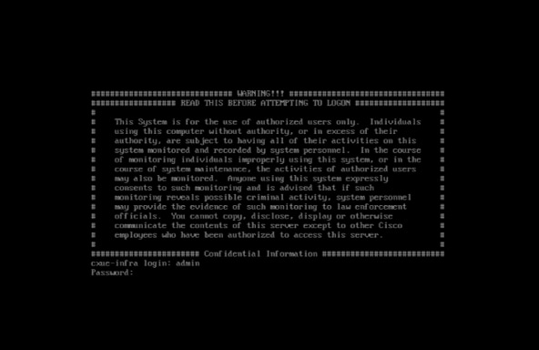 Log In
- Log in to the console using the default network credentials by entering “admin” for both the login name and password. The Configuration Settings displays.
Note: The default credentials are provided for initial setup only as there is no data to protect at this stage of installation.
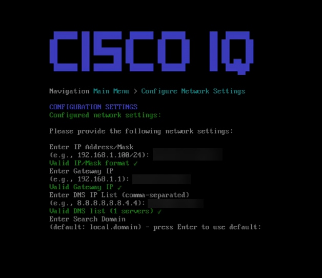 Configuration Settings
- Enter “1” and press Enter to configure network settings.
- Provide the following network settings:
Note: Users can press Enter to use detected values where available.
- IP address
- Gateway IP
- DNS IP list
- Search domain
- NTP server list
Note: Inputting multiple NTP servers using a comma-separated format is supported.
- Configure the NTP authentication by pressing N to proceed without an authentication method
OR
Press Y and enter the corresponding number of an option listed below:
- Traditional key-based authentication: Uses provided credentials for secure time synchronization; after selecting this option, enter a valid algorithm and a hex key
- Network Time Security (NTS): Uses the NTS protocol to provide secure NTP communication
Note: NTP information can be validated in the UI after installation by navigating to System Settings.
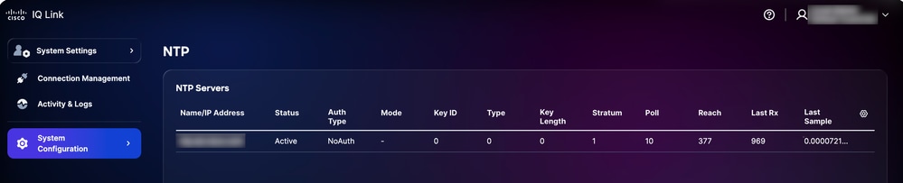 NTP Validation in UI
- Enter and confirm a password after reviewing the on-screen password requirements.
- Review the summary and press Y to continue. Setup can take a few minutes.
- Once a success message is received, press Enter to return to the main menu.
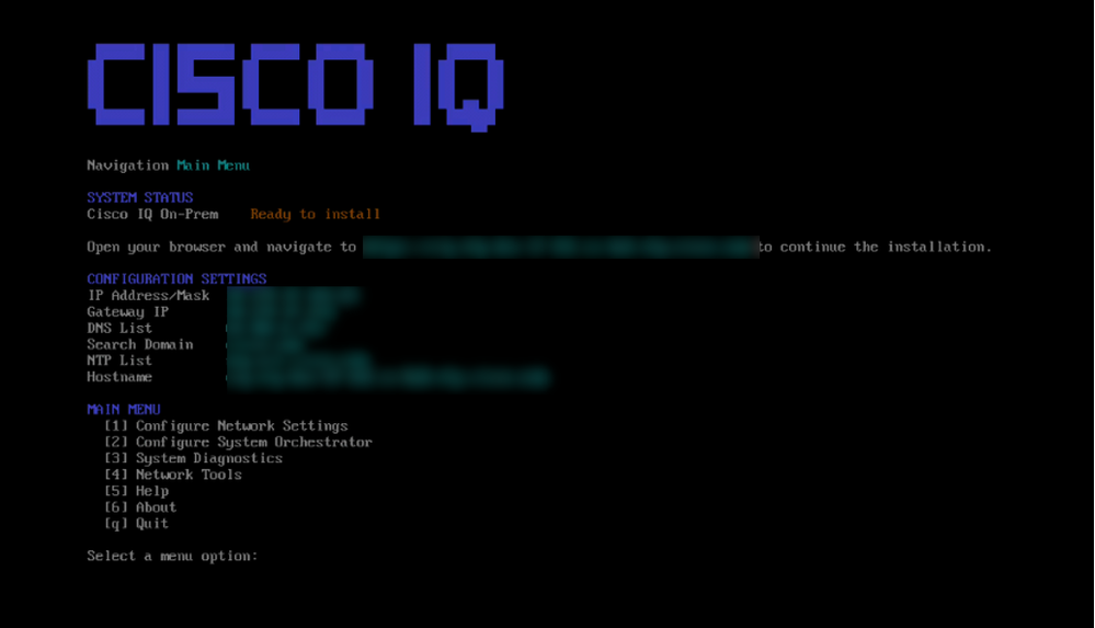 Cisco IQ Menu
Network settings are now configured, but VA has not yet been installed. It is recommended to return to hypervisor and take a Snapshot of the new VM for future reference. At this point, you can also initiate a Secure Shell connection using the newly configured IP address and credentials.
This completes manual configuration of VA.
Installing VA for Air-Gapped Mode
To install VA:
- Navigate to the VA installer web interface (https://<CIQ-HOST-FQDN>/installer/welcome) (received after configuring VA in VMs.). The Cisco IQ Virtual Appliance Installer page displays.
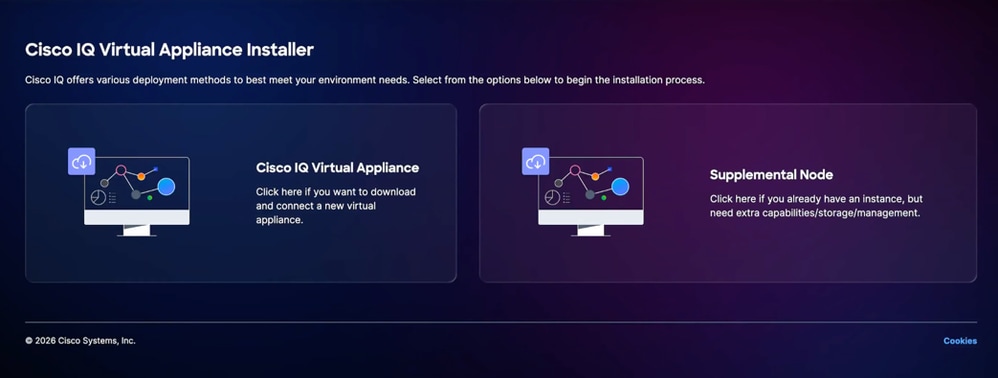 Virtual Appliance Installer Page
 - Click Cisco IQ Virtual Appliance. The Install Cisco IQ Virtual Appliance page displays.
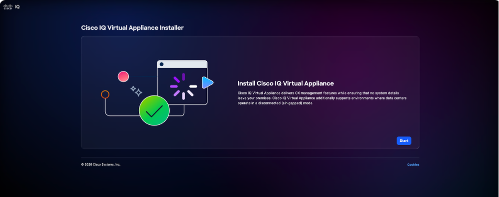 Install Virtual Appliance
 - Click Start. The Configure Internal Network tab displays.
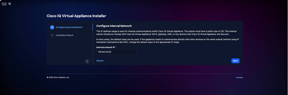 Configure Internal Network
 - Enter the Internal IP Range.
Note: Ensure the internal subnet does not overlap with your VM IP, gateway, DNS, or reachable network ranges.
5. Click Next. The Installer Result page displays.
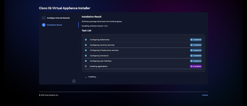 Installation Result
6. Wait until all tasks displayed are complete. Upon successful completion, the browser automatically navigates to the Cisco IQ VA login page. The installation completion can take up to two (2) hours.
 Login
Login
Once successfully logged in, the system is ready to discover devices and supports the Assets application without AI support.
Modules and Rules Installation
To expand your system's capabilities, you can download additional modules and rules directly from the Cisco IQ SaaS portal and complete the installation in VA. See Installing Packages in Operations Guide for more details.
Note: The Assets module is pre-installed in the VA installer, and available for immediate use. You can upgrade the asset module or asset rule version like any other module and rules as needed.
Multi-Node Support
The multi-node architecture allows you to expand a standalone VA for horizontal scalability and add on GPU support. The horizontal scalability helps with providing increased resource capacity for processing a higher number of supported devices and more module deployments. This configuration enables the addition of supplementary nodes to a primary management node, allowing the system to scale based on your specific workload requirements.
Enabling the multi-node capability is essential to add a GPU node. This integration allows the On-Prem environment to leverage GPU resources for AI inferencing. This section provides detailed guidance on connecting the GPU as a supplemental node for the On-Prem, which is necessary for users to utilize GPU capabilities effectively.
Network Requirements
VA supports a single network interface.
Port Requirements
The following table outlines the network ports required for Cisco IQ VA communication in a multi-node environment.
Table 4: Port Requirements
| Port(s) |
Protocol |
Description |
Node Type |
| 22 |
TCP |
Used for Administrator CLI and Cisco Support debugging sessions |
Management and supplementary nodes |
| 443 |
TCP |
Used for communication between Cisco IQ On-Prem and web browsers, as well as endpoint targets |
Management and supplementary nodes |
| 53, 123, 161 |
UDP |
Used to send and receive DNS, NTP, and SNMP traffic |
Management and supplementary nodes |
| 10250, 10256 |
TCP |
Used for Kubernetes communication between the node |
Management and supplementary nodes |
| 179 |
TCP |
Used for VXLAN control plane (BGP) between nodes |
Management and supplementary nodes |
| 4789 |
UDP |
Used for VXLAN traffic between nodes |
Management and supplementary nodes |
| 500, 4500 |
UDP |
Used for IPSec IKE traffic between nodes |
Management and supplementary nodes |
| All |
ESP (50) |
Used for IPSec ESP traffic between node |
Management and supplementary nodes |
| 6443 |
TCP |
Used for Kubernetes API server |
Management node only |
Note: Multi-node clustering is supported only for standard VA deployments.
Note: A supplementary node must be the exact same version as the primary management node during the initial join process.
Note: The current multi-node implementation does not provide High Availability (HA) for the management plane. If the primary management node becomes unavailable, cluster operations will be impacted.
Adding a Supplemental Node
Adding a supplementary node requires the same process as installing the VA. Once you have downloaded the VA installer from the Package Catalog in Cisco IQ (SaaS), install it on the chosen hypervisor. See Deploying VA on Hypervisor for more details.
Before adding a supplementary node, ensure the first node is fully configured as a standard VA. To add a supplementary node:
- Navigate to System Configuration > Node Management.
- Verify that the primary node under Node column with successful status displays.
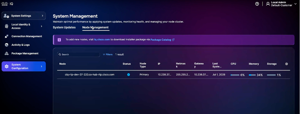 Node Management
 - Navigate to VA Installer. The following options display:
- Cisco IQ Virtual Appliance
- Supplemental Node
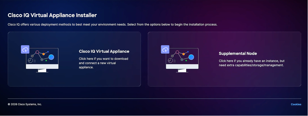 Supplemental Node
- Click Supplemental Node option. The Supplemental Node Installer page displays.
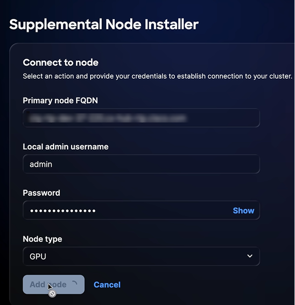 Supplemental Node Page
 - Enter Primary node FQDN.
- Enter Local admin username.
- Enter Password.
- Choose Node type from the drop-down list.
Note: You can choose GPU worker node. When choosing GPU worker nodes, ensure your hypervisor environment (for example, VMware or Hyper-V) is configured with the necessary hardware to support GPU devices, as these are required for GPU node accessibility. See Deployment Options to learn more.
9. Click Add node. The "Supplemental node ready" message displays after successful node addition.
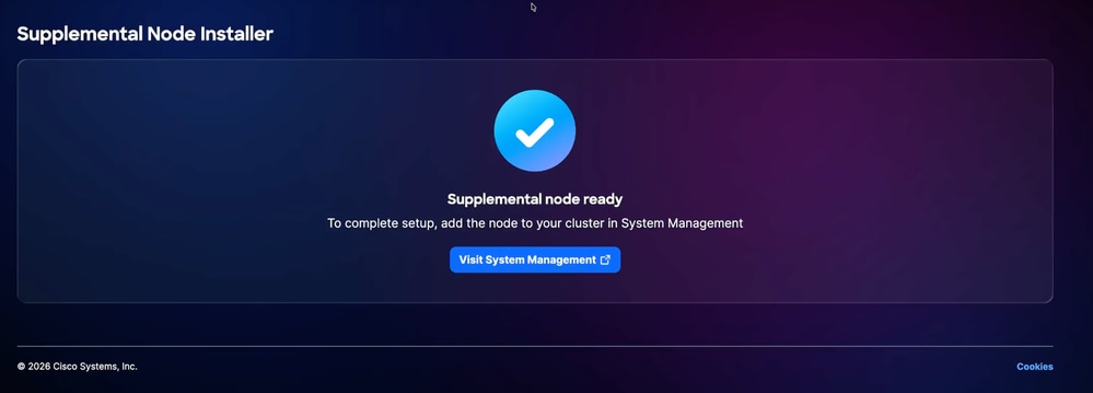 Supplemental Node Ready
10. Once “Supplemental node ready” displays, click the Visit System Management link or navigate to System Management > Node Management to trigger the add node action to complete the integration.
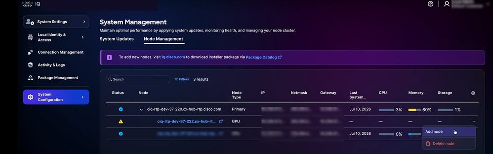 Add Node
11. Click More menu icon > Add Node. The Add GPU Node window displays.
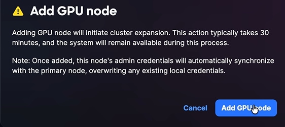 Add GPU Node
12. Click Add GPU Node. Once the node is successfully added, it displays in cluster.
Cluster Synchronization and Management
Upon adding a worker node, the administrative credentials of the primary management node automatically synchronize with the worker node. The access to the worker node must be performed using these synchronized credentials.
Note: The cluster dynamically manages module distribution. When a module requires advanced processing capabilities, the system checks for the availability of GPU-enabled nodes. If a GPU worker is present and the appropriate module package is installed, the system enables these advanced features. If the cluster lacks the necessary hardware resources, the system will operate in a non-accelerated mode to maintain stability.
Support
You can create VA and module-specific support cases from Cisco IQ SaaS. The Support module is available in Cisco IQ SaaS and offers a consolidated view of your support cases. It enables you to filter, sort, and customize the case list view, providing visibility into both open and closed cases you are entitled to access. For more detailed information about the Support module in Cisco IQ SaaS, see the Cisco IQ SaaS Getting Started Guide.
Note: Cisco IQ VA customers can access most Cisco IQ SaaS Support module features, including opening Technical Assistance Center (TAC) cases related to Cisco IQ VA and its modules, as well as creating and managing product cases.
Creating a Support Case
You can create VA and module-specific cases in Cisco IQ SaaS. To create a case:
- Log in to Cisco IQ (SaaS).
- Click the Help icon > Report an Issue. The Report an Issue window opens.
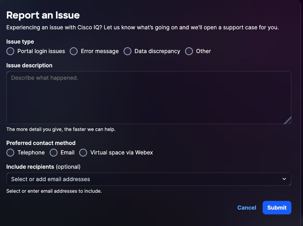 Report an Issue
- Provide the required details.
- Click Submit.
Revision History
| Revision | Publish Date | Comments |
|---|---|---|
2.0 |
August 20, 2026
|
GA Release |
1.0 |
July 23, 2026
|
Initial Release |