Understand Switch Onboarding through Catalyst Center Plug and Play
Available Languages
Contents
Introduction
This document describes Catalyst Center Plug and Play for automated switch onboarding, the full lifecycle, discovery methods, and troubleshooting.
Description
Catalyst Center Plug and Play (PnP) automates Cisco Catalyst switch onboarding through the Cisco IOS® XE embedded PnP agent. This process enables secure discovery, authentication, and initial provisioning with minimal manual effort, significantly speeding up deployments and improving configuration consistency. By supporting scalable rollouts through standardized settings and optional Day-0 templates, PnP ensures a reliable deployment at scale.
The document outlines the complete onboarding lifecycle, including PnP workflows, discovery methods, onboarding options, and certificate validation. It also provides detailed guidance on device claiming, verification, troubleshooting, and industry best practices.
Audience
This document is intended for network administrators, deployment engineers, and system integrators who deploy and manage Cisco Catalyst switches through Catalyst Center.
Requirements
It is preferable that readers of this document have a basic working knowledge of these topics:
- Catalyst Center
- Cisco Catalyst switches
- Network automation and provisioning
- DHCP and DNS fundamentals
Prerequisites
Ensure that these prerequisites are met before starting the onboarding process:
- Catalyst Center 2.3.7.9 or later is installed and operational.
- Cisco Catalyst switches run a supported Cisco IOS XE release 16.12.x or later.
- Network connectivity is available between the Catalyst switches and Catalyst Center.
- The DHCP server is configured with Option 43 pointing to the Catalyst Center's enterprise interface IP address or FQDN.
- Switches are in factory-default (out-of-box) state, and the pnpa service reset command available on IOS XE 16.12.1 and later can be used to reset a switch to this state.
Plug and Play Concept Overview
Review these key concepts that explain how Catalyst Center Plug and Play onboards a new switch.
1. DHCP Discovery of PnP Server
When a factory-default Cisco Catalyst switch powers on, the PnP agent attempts to discover a Plug and Play controller (like Catalyst Center) using DHCP.
The discovery process use the standard DHCP exchange:
- DHCP Discover
- DHCP Offer
- DHCP Request
- DHCP Acknowledgement
If configured correctly, the DHCP server includes Option 43, which provides the switch with connection details for the PnP server.
2. DHCP Option 43 Format
The DHCP Option 43 value is a semicolon-separated ASCII string that specifies how the switch connects to the PnP server.
Example:
option 43 ascii 5A1N;B2;K4;I10.127.212.43;J80;
Option 43 Field Definitions
- 5A1N
- 5 – PnP suboption
- A – Active mode (device initiates communication)
- 1 – PnP agent template version
- N – Debug disabled (D enables debugging)
- B2 – PnP server IP address type
- 1 – Hostname
- 2 – IPv4 address
- 3 – IPv6 address
- K4 – Transport protocol
- 4 – HTTP
- 5 – HTTPS
- I – PnP server IP address or FQDN
- J – TCP port number
Optional parameters include:
- T – Trustpool certificate bundle URL (mandatory for HTTPS)
- Z – NTP server IP address (mandatory when using Trustpool security)
3. DHCP Option 43 Configuration Examples
- Example 1: Option 43 IPv4 configuration: 10.127.212.43 [Catalyst Center enterprise interface IP address]
ip dhcp pool pnp_pool
  network 10.127.212.0 255.255.255.0
  option 43 ascii 5A1D;B2;K4;I10.127.212.43;J80;
default-router 10.127.212.49- Example 2: Option 43 hostname configuration: catc1.cisco.com [Catalyst Center FQDN]
ip dhcp pool pnp_pool
  network 10.127.212.0 255.255.255.0
  option 43 ascii 5A1D;B1;K4;Icatc1.cisco.com;J80;
  default-router 10.127.212.49
- Example 3: Option 43 IPv6 configuration: 2001:60:60:60::133 [Catalyst Center enterprise interface IPv6 address]
ipv6 dhcp pool pnp_pool
 address prefix 2001:70:70:70::/64
 link-address 2001:70:70:70::7/64
 vendor-specific 9
  suboption 16 ascii "ciscopnp"
  suboption 17 ascii "5A1D;B3;K4;I2001:60:60:60::133;J80"
4. PnP startup VLAN Behaviour
By default, a factory-reset switch uses VLAN 1 for PnP management. Cisco recommends using a dedicated management VLAN in production environments. This is the command to configure a Custom PnP Startup VLAN:
pnp startup-vlan <vlan-id> This command must be configured on an upstream switch. The upstream switch communicates the PnP startup VLAN to the new switch using Cisco Discovery Protocol (CDP). The downstream switch then:
- Disables DHCP on VLAN 1
- Enables DHCP on the configured startup VLAN
- Updates the trunk to allow the new VLAN
Catalyst Center Certificate Verification
Secure onboarding requires that the Catalyst Center SSL certificate includes the IP address or FQDN used by the switch in the Subject Alternative Name (SAN) field.
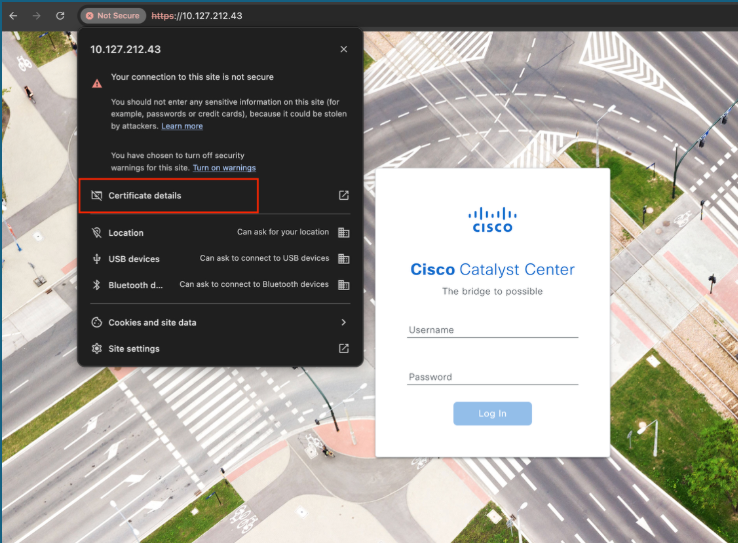
GUI Verification
- Open the Catalyst Center login page in a browser
- View site information
- Open certificate details
- Verify SAN entries under Extensions
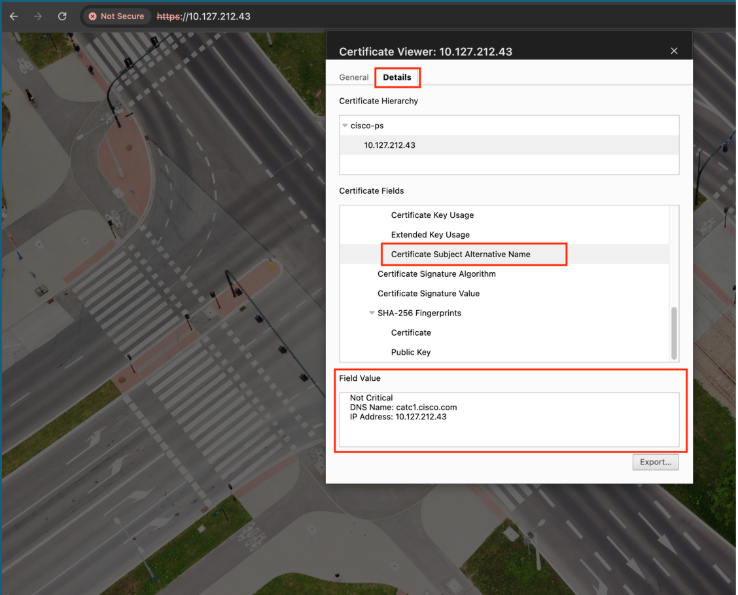

Note: If the SAN or Subject Alternative Name field contains:
- Only DNS Name – Configure the DNS name in the option 43 string.
- Only IP Address – Configure the IP address in the option 43 string.
- Both IP Address and DNS Name – Configure the IP address in the option 43 string.
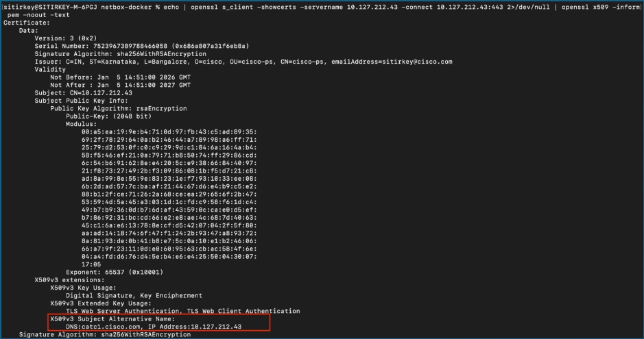
CLI Verification
To verify this, we need the Catalyst Center IP address and a machine that can reach the Catalyst Center server. Run this command in the terminal or at the command prompt.
echo | openssl s_client -showcerts -servername <catc-ip-address> -connect <catc-ip-address>:443 2>/dev/null | openssl x509 -noout -text
Verify that the SAN field contains the appropriate IP address or FQDN.
Network Diagram
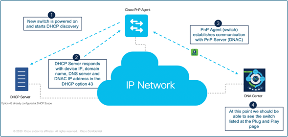
Cisco PnP automates new device onboarding by enabling discovery, configuration, and management with minimal manual effort. When a new switch powers on, it sends a DHCP discovery request, and the DHCP server returns network details, including the Catalyst Center (PnP server) IP address through DHCP Option 43. Using this information, the switch’s PnP agent securely connects to the PnP server over the IP network. After the connection is established, the device is authenticated and identified, then added to the Plug and Play inventory, where administrators can apply configurations and complete provisioning quickly and consistently.
Switch Onboarding Methods
Review the various onboarding methods in this section through which a switch can be onboarded into the Plug and Play inventory of Catalyst Center.
1. Onboard using VLAN1
This method uses the default VLAN 1 for PnP management
Requirements
- VLAN 1 SVI is configured on the upstream switch.
- DHCP Server with Option 43 configured
- DNS resolution for the Catalyst Center FQDN
Procedure on the Upstream switch
Step 1. Configure VLAN 1's SVI.
config t
interface Vlan1
  ip address 10.127.212.49 255.255.255.0
Step 2. Configure a DHCP pool with Option 43 (Note: We can use the Option 43 parameter with either the IPv4 address or FQDN of Catalyst Center).
config t
ip dhcp pool pnp_pool
  network 10.127.212.0 255.255.255.0
  option 43 ascii 5A1D;B2;K4;I10.127.212.43;J80;
or
config t
ip dhcp pool pnp_pool
  network 10.127.212.0 255.255.255.0
  option 43 ascii5A1D;B1;K4;Icatc1.cisco.com;J80;
  default-router 10.127.212.49
  dns-server 10.127.212.1
Step 3. Configure a trunk interface to the new switch.
config t
interface GigabitEthernet1/0/5
  description PnP_Trunk
  switchport mode trunk
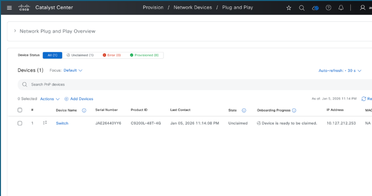
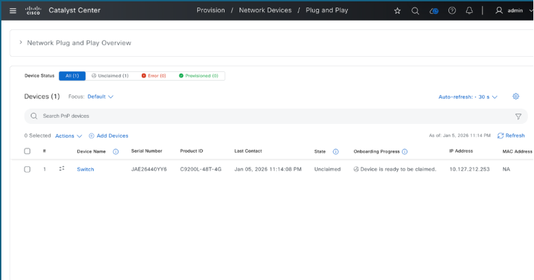
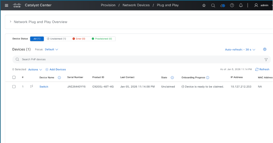
Step 4. Verify that the switch appears on Catalyst Center's Provision > Plug and Play page.
2. Onboard using custom VLAN
This method uses a dedicated VLAN for management.
Requirements
- Custom VLAN SVI configured on the upstream switch.
- DHCP Server with Option 43 configured.
- DNS resolution for the Catalyst Center FQDN.
- Trunk allows the custom VLAN along with any other VLANs necessary for other traffic.
Procedure on the upstream switch
Step 1. Configure the custom VLAN's SVI.
config t
interface Vlan302
  description PnP_Vlan
    ip address 10.127.212.49 255.255.255.0
Step 2. Configure a DHCP pool with Option 43 (Note: We can use the Option 43 parameter with either the IPv4 address or FQDN of Catalyst Center).
config t
ip dhcp pool pnp_pool
  network 10.127.212.0 255.255.255.0
  option 43 ascii 5A1D;B2;K4;I10.127.212.43;J80;
or
config t
ip dhcp pool pnp_pool
  network 10.127.212.0 255.255.255.0
  option 43 ascii 5A1D;B1;K4;Icatc1.cisco.com;J80;
  default-router 10.127.212.49
  dns-server 10.127.212.1
Step 3. Configure the custom VLAN as the PnP VLAN.
config t
pnp startup-vlan 302
Step 4. Configure the trunk interface to new switch.
config t
interface GigabitEthernet1/0/5
  description PnP_Trunk
  switchport mode trunk
  switchport trunk allowed vlan 302
Step 5.Verify that the switch appears on Catalyst Center's Provision > Plug and Play page.
3. Onboard Switch using the management port
This method leverages the management interface of the switch.
Requirements
- Custom VLAN SVI configured on the upstream switch
- DHCP Server with Option 43 configured
- DNS resolution for the Catalyst Center FQDN
Procedure on the upstream switch.
Step 1. Configure the VLAN's SVI.
config t
interface Vlan302
    ip address 10.127.212.49 255.255.255.0
    ip helper-address 10.127.212.1
Step 2. Configure the access interface to the new switch.
config t
interface GigabitEthernet1/0/5
  switchport mode access
  switchport access vlan 302
Step 3.Verify that the switch appears on Catalyst Center's Provision > Plug and Play page.
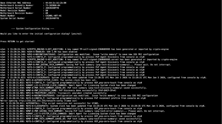
4. Switch Console logs
Here is what appears on the switch's console when DHCP is used for Plug and Play.
Onboarding Switch to Catalyst Center without Day-0 templates
To onboard a new switch into Catalyst Center's inventory, complete these required procedures once the device is visible and claimable on the Plug and Play page.
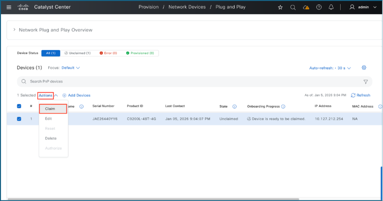
1. To claim switches:
- Select the checkboxes for the switches to be claimed.
- Navigate to Actions > Claim.
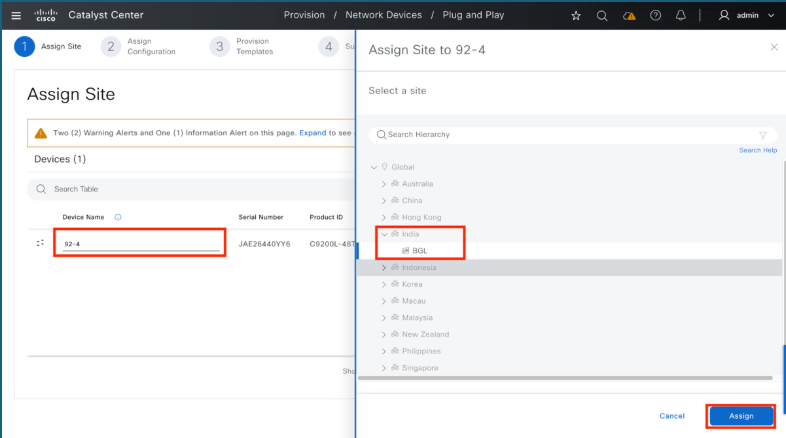
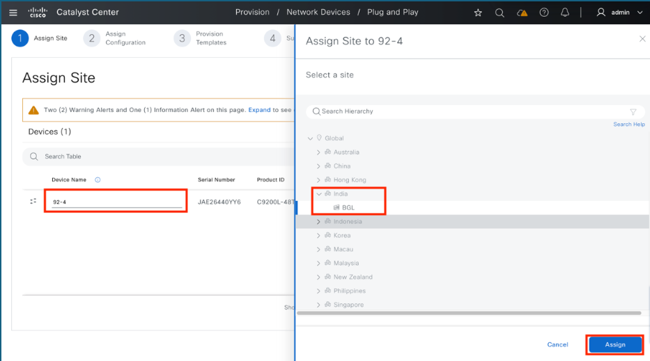
2. To name and map the switch:
- Enter the name in the Device Name field and click Assign.
- Choose the correct site or building, click Assign again, and then click Next.
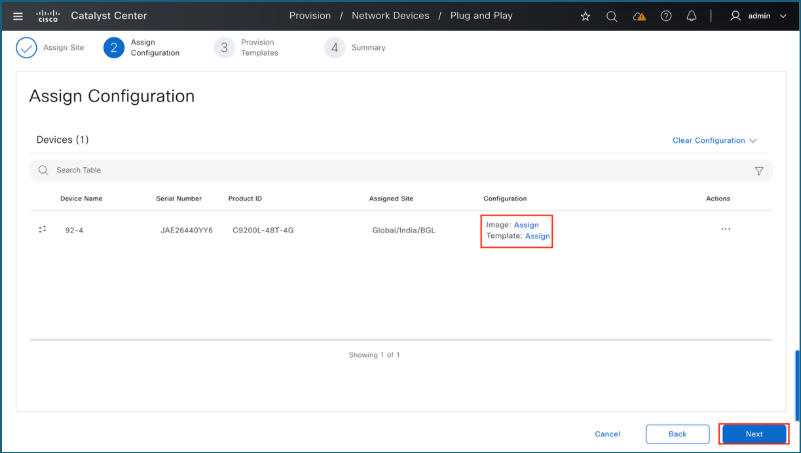
3. Assign Software Image or Template (optional):
Use this step to upgrade the switch to a specific software version or apply a Day-0 configuration template.
- Click Assign next to Image to specify the software version.
- Click Assign next to Template to apply a template configuration.
- Click Next after the desired assignments are complete.
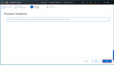
4. Provision templates
When claiming the device without the use of templates, bypass this configuration step by selecting Next.
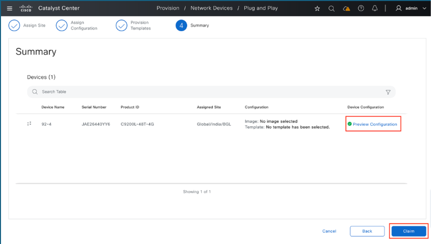
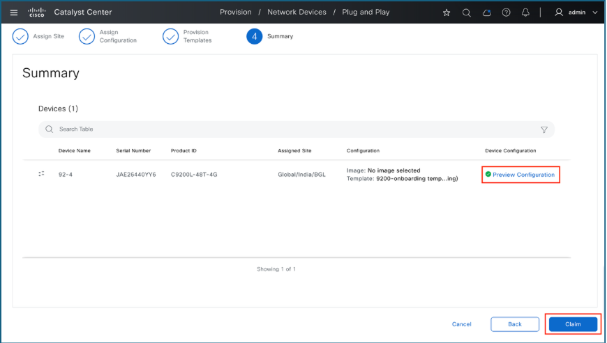
5. Summary
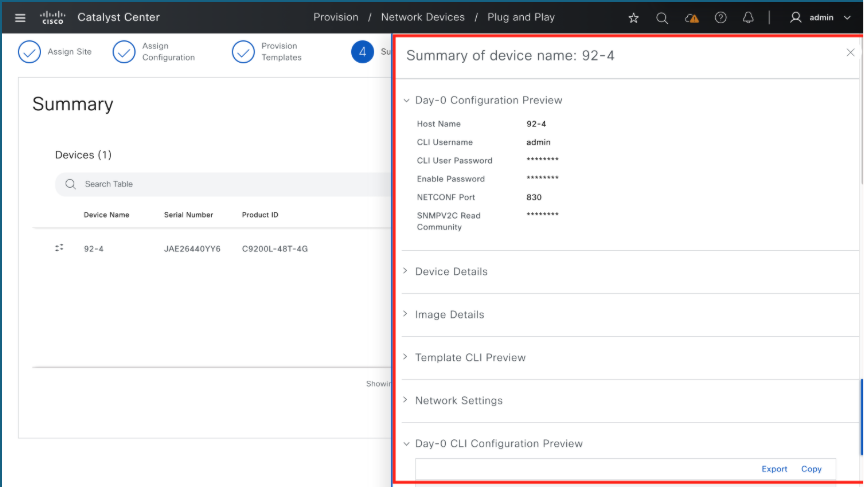
Use the Summary page to review the configuration before it is provisioned by Catalyst Center.
- Click Preview Configuration.
- Expand the individual sections to verify the settings.
- Once verified, click Claim.
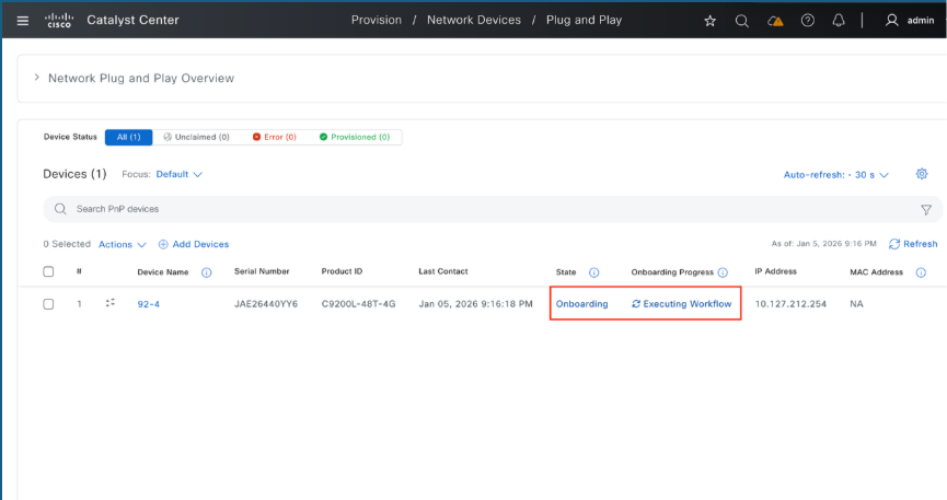
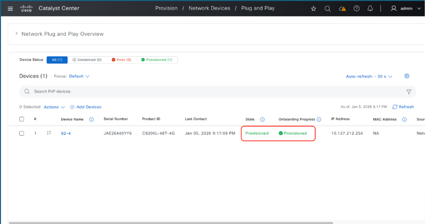
6. Monitor the Claiming Process
Upon initiating the claim, the interface returns to the Plug and Play dashboard. Monitor the device state, a transition to Provisioned indicates the switch has been successfully claimed and added into Catalyst Center's inventory.
Onboarding Switch to Catalyst Center with Day-0 templates
When the new switch is ready to be claimed on Catalyst Center's Plug and Play page, apply a Day-0 template to include additional configuration during the claim process.
1. Create Day-0 or Onboarding Template
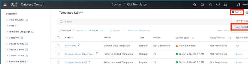
- Navigate to Design > CLI Templates.
- Select Add > New Template.
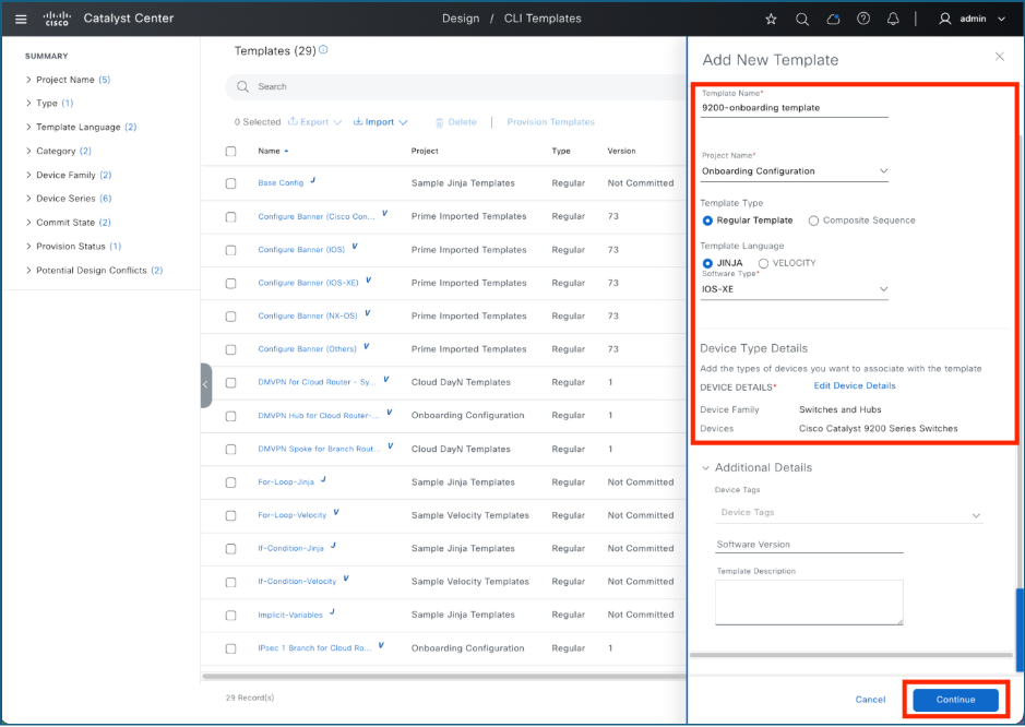
2. Add Template Details
In the side panel, enter these template specifications:
- Template Name
- Project Name: For Day-0 templates, always select Onboarding Configuration.
- Template Type, Language, and Software Type: Select the appropriate values from the menus.
- Click Continue to proceed.
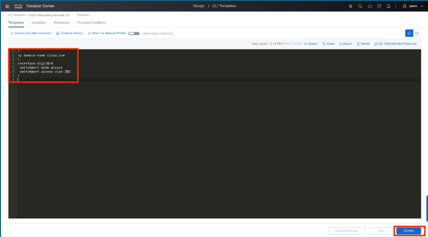
3. Edit the Template
Enter the configuration to be deployed to the switch in the CLI Template Editor. In this example a domain name and an access port are configured. After adding the configuration to the CLI Template Editor, click Save and then Commit to finalize the changes.
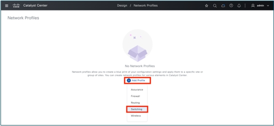
4. Create Network Profile
- Navigate to the Design menu and select Network Profiles.
- Click the Add Profile button.
- Choose the appropriate profile type from the list (for example, Switching).
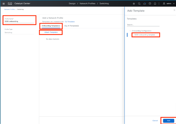
5. Add template and edit network profile settings
- Enter a Profile Name: Provide a name for the network profile.
- Access Templates: Click on Onboarding Template(s) and then select Attach Templates.
- Choose Template: Locate and select the required template from the Onboarding Configuration directory.
- Finalize: Click the Add button to complete the process.
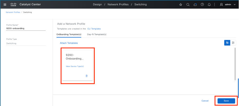
6. Save the profile
- Verify Template: After adding the template, ensure it appears in the list under Onboarding Template(s).
- Save Profile: Click Save button to finalize and store the profile settings.
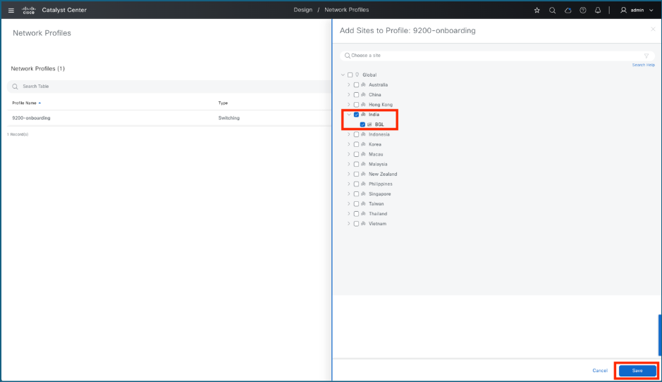
7. Assign network profile to the site where switch/switches are to be onboarded
- Initiate Assignment: Click the Assign Site option for the network profile that was just created.
- Choose the Site: Select the specific site where the switches are to be onboarded.
- Confirm: Click Save to finalize the assignment.
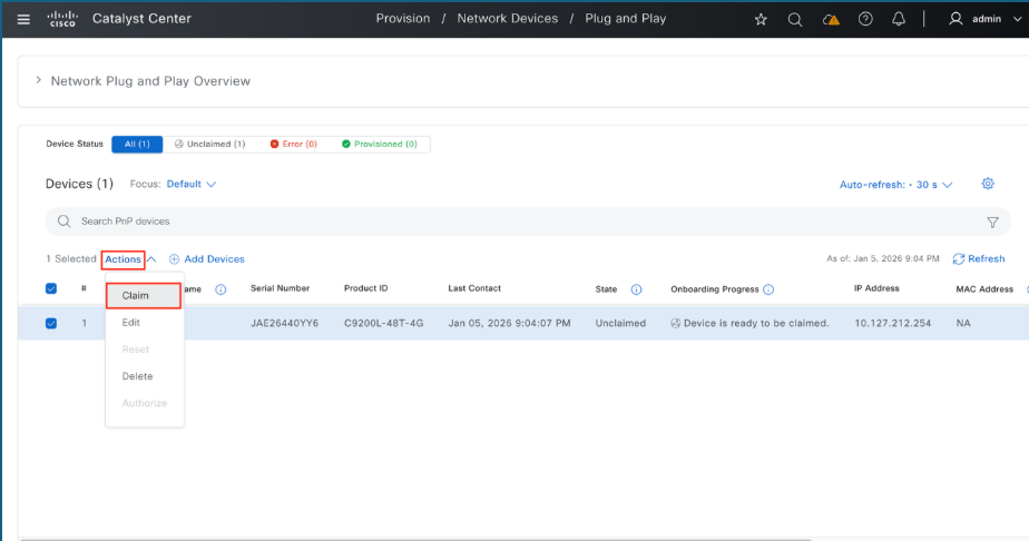
8. Claim Switches
- Navigate to Plug and Play: Go to Provision menu and select Plug and Play.
- Select Devices: Locate the switch or switches to be claimed and click the checkbox next to each switch's name.
- Initiate Claim: Navigate to the Actions menu and select Claim.
9. Assign a name for the switch and assign to a site
- Name the Device: Enter the desired name for the switch in the Device Name field.
- Initiate Assignment: Click the Assign button.
- Select Location: Choose the appropriate site or building, click Assign again, and then click Next to proceed.
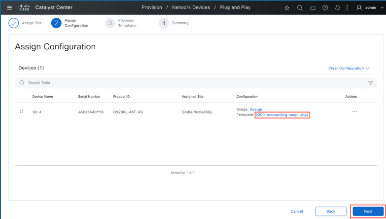
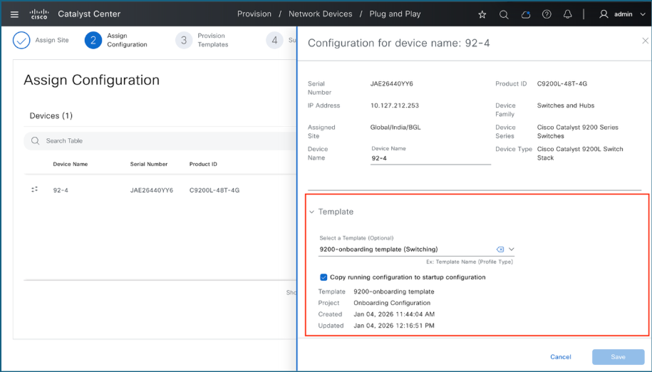
10. Assign a Day-0 template
- Select the Template: Click on the template that has been automatically selected next to the Template option.
- Review Details: Carefully verify the configuration details of the assigned template.
- Proceed: Once you have confirmed the template assignment, click Next.
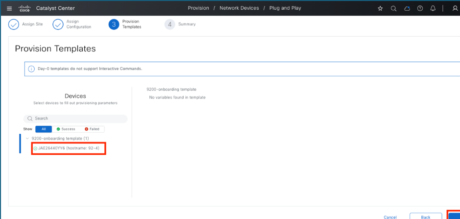
11. Provision templates
- Select Device: Under the template section, click on the specific device you are configuring.
- Identify Variables: Check for any required variable values associated with the template.
- Enter Values: If any variables are mandatory, fill in the necessary values.
- Proceed: Click Next to move to the next step.
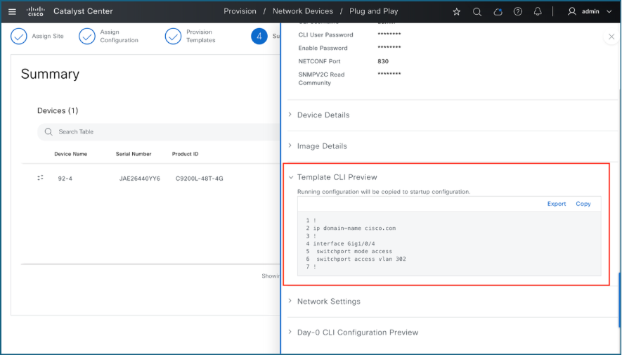
12. Summary
- Review Configuration: On the Summary page, audit the configuration settings prepared by Catalyst Center.
- Preview Details: Click on Preview Configuration to see the pending changes.
- Verify Sections: Expand each section to inspect the specific configuration details.
- Finalize: Once you have verified the settings, click Claim to proceed.
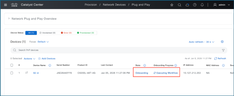
13. Monitor claim progress
You are redirected to the Plug and Play page to track the device progress.
- Monitor Status: Observe the device state as the claiming process proceeds.
- Confirm Completion: When the status updates to Provisioned, the switch has been successfully claimed and integrated into the Catalyst Center inventory.
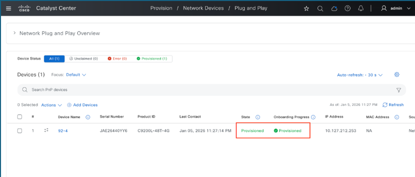
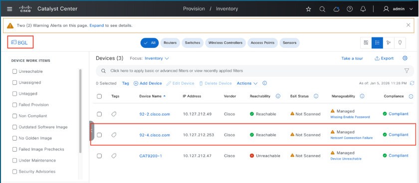
Verification
- Access the Provision Menu: Open the Provision tab in the main page.
- View Inventory: Select the Inventory option.
- Verify Status: Check the list to confirm that the switches have been successfully provisioned.
Bulk Import of Devices into Catalyst Center Plug and Play Inventory
To streamline large network rollouts, Catalyst Center supports a bulk import method for staging devices in advance. This process involves uploading device identifiers such as PIDs, serial numbers, and optional site or template data allowing the system to automatically onboard devices as soon as they are powered on and connected.
1. Prerequisites
To ensure a successful bulk import, these requirements must be met:
- The Catalyst Center instance must be reachable and operational.
- Hardware must be officially supported by the Cisco Plug and Play service.
- Device serial numbers and PIDs must be accessible.
- Target site hierarchies must be pre-configured in the Catalyst Center environment.
2. Bulk Import Procedure
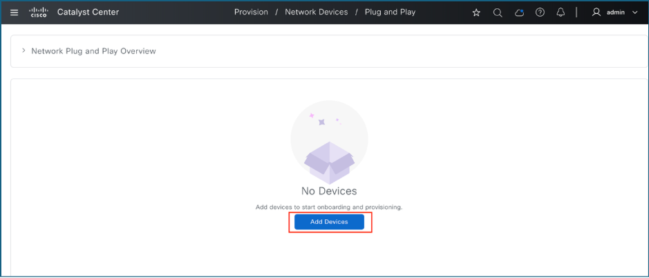
- Log in to Catalyst Center
- Navigate to Provision > Plug and Play
- Click on Add Devices
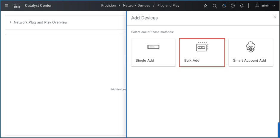
4. Click on Bulk Add
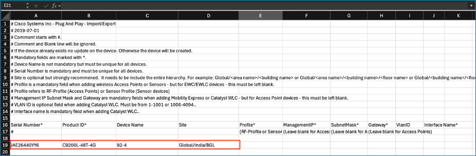
5. Click on Download File Template to download the sample CSV file
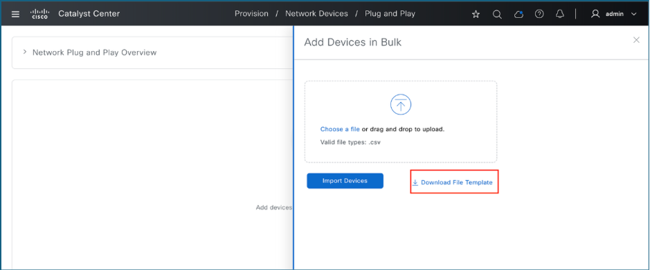
6. Populate the CSV file with the required device details.
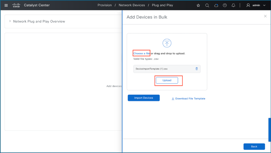
7. Upload the completed CSV file.
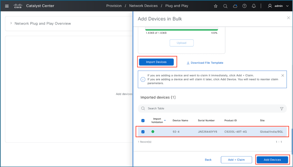
8. Import the devices from the CSV file and add them into the PnP inventory
9. The devices appear in the inventory as Not Contacted.
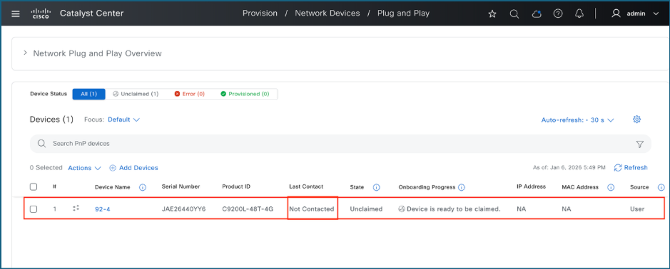
10. Once the device contacts Catalyst Center, it is ready to be claimed.
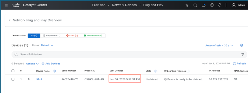
Troubleshooting
If the switch does not appear on Catalyst Center's Plug and Play page, these are the steps to identify and resolve the issue.
1. PnP Connectivity Validation
These commands validate PnP connectivity to Catalyst Center.
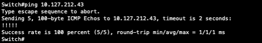
1.1. ICMP Reachability
Verify ICMP connectivity by pinging Catalyst Center's enterprise interface IP or Virtual IP (VIP) address. Ensure that Catalyst Center is reachable via ping.
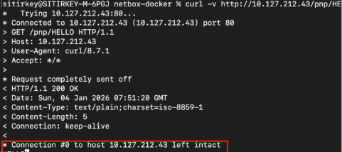
1.2. HTTP HELLO validation
Plug and Play (PnP) fails if Catalyst Center does not respond to HELLO validation requests. To verify connectivity, run this command from a device terminal or command prompt: curl -v http://<Catalyst Center IP>/pnp/HELLO
Confirm that a "HELLO" response is received.
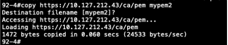
1.3. HTTPS certificate retrieval
PnP functionality fails if the Catalyst Center server's certificate cannot be manually retrieved over HTTPS. To verify this, use this command: copy https://<catc-ip-address>/ca/pem mypem2
Confirm that the file transfer completes without errors.
1.4. PnP profile status
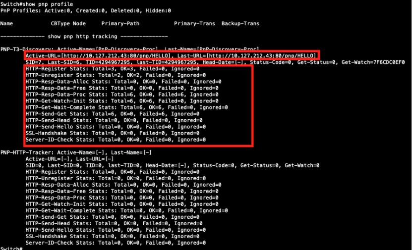
If a switch does not appear on Catalyst Center's PnP page, examine the PnP HTTP connectivity by executing the commandshow pnp profile
- Verify that PnP is using the correct Active-URL.
- Confirm that "Failed Counters" in the HTTP statistics is 0. A value greater than 0 indicates reachability issues between the switch and the Catalyst Center. This image illustrates a scenario involving reachability issues.
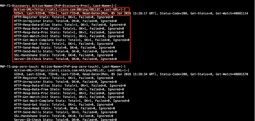
This example illustrates a scenario with no reachability issues.
2. DHCP Validation
These commands help validate DHCP configuration and connectivity.
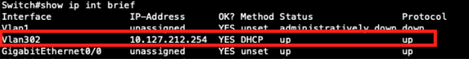
2.1. Verify DHCP IP address assignment
Execute the command: show ip interface brief, to verify that the PnP VLAN SVI has successfully received an IP address from the DHCP server.
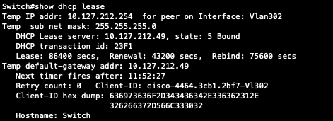
2.2. Confirm Lease Server
Execute the command show dhcp leaseto verify the DHCP lease server information.
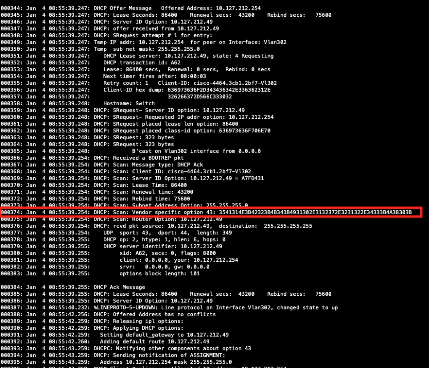
2.3. Validate Option 43 using debug logs
To validate Option 43, enable DHCP debugging with the command debug dhcp detail. After enabling the debug perform a shutdown and no shutdown on the interface to restart the DHCP process. In the logs, locate the section "DHCP: Scan: Vendor specific option 43:". Copy the hex string as shown on this section, convert it to text using a suitable hex-to-ASCII converter, and verify that the resulting string correctly points to Catalyst Center.
Best Practices
- Ensure the switch is in its factory default state. If it was previously provisioned, use the pnpa service reset command to reset it.
- Avoid interrupting the PnP process through the console.
- Verify certificates and DNS resolution prior to deployment.
Revision History
| Revision | Publish Date | Comments |
|---|---|---|
1.0 |
18-May-2026
|
Initial Release |
 Feedback
Contact Cisco
- Open a Support Case

- (Requires a Cisco Service Contract)