Understand AP Onboarding through Catalyst Center Plug and Play
Available Languages
Contents
Introduction
This document describes Cisco PnP for zero-touch AP onboarding with Catalyst Center.
Description
Plug and Play (PnP) services on Catalyst Center provide an automated, zero-touch deployment process that simplifies Access Point (AP) provisioning and site configuration. This guide outlines detailed steps for onboarding new Access Points across various real-life deployment scenarios, including both intent-based and non-intent-based approaches. Additionally, it provides comprehensive troubleshooting guidance to ensure a smooth and efficient deployment experience.
Requirements
Knowledge of these topics:
- Cisco Catalyst 9800 Series Wireless Controllers
- Cisco Access Points
- Catalyst Center Wireless Automation and Provisioning
- Catalyst Center Assurance Deployments
- Catalyst Center Per-Device Configuration (PDC) / Campus Automation
Prerequisites
- Cisco Catalyst Center with 2.3.7.9 or higher.
- Cisco Catalyst 9800 Series Wireless Controller
- Option 43 configured on the AP’s DHCP Server Config with Catalyst Center’s Enterprise Interface IP address. See the example on Step 1.
Step 1 : Option 43 configured on the AP’s DHCP Server Config with Catalyst Center’s Enterprise Interface IP address
Catalyst center enterprise IP mut be the option 43 IP since we are using Onboarding from Catalyst Center, here are two examples:
- Example IPv4 for Enterprise IP addres of Catalyst Center : 9.7.144.14
ip dhcp pool VLAN137
  network 9.7.137.0 255.255.255.0
  default-router 9.7.137.1
  option 43 ascii 5A1N;B2;K4;I9.7.144.14;J80
- Example IPv6 for Enterprise IP addres of Catalyst Center : 2001:60:60:60::133
ipv6 dhcp pool AP_PNP
  address prefix 2001:70:70:70::/64
  link-address 2001:70:70:70::7/64
  vendor-specific 9
  suboption 16 ascii "ciscopnp"
  suboption 17 ascii "5A1D;B3;K4;I2001:60:60:60::133;J80"
- Example for DNS for Enterprise IP addres of Catalyst Center
ip dhcp pool vlan200
  network 10.200.0.0 255.255.0.0
  default-router 10.200.0.1
  domain-name pnpagent.test.com
dns-server 8.8.8.8 - APs must be out of box mode or in factory reset mode for PnP agent to start on the AP.
- Network connectivity must exist between APs, Catalyst Center, and Wireless controller.
Network Diagram
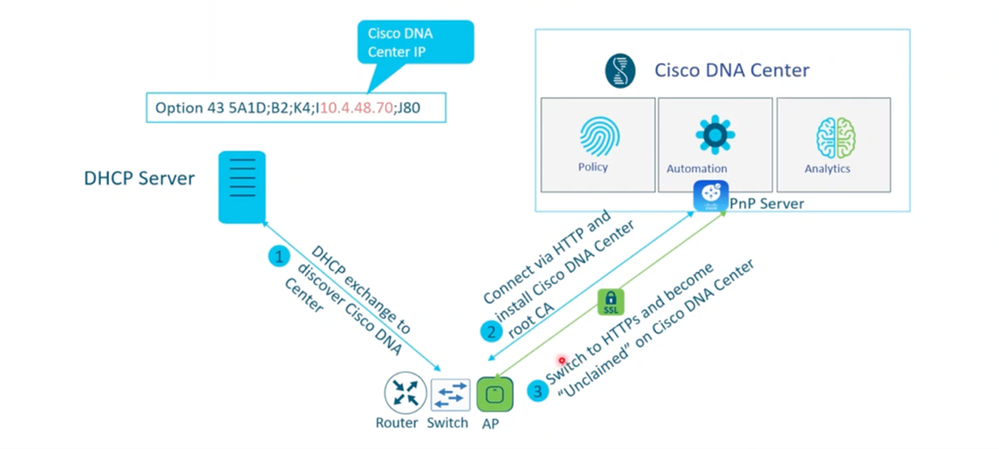 AP PnP Process Diagram
Step 2: AP addition to PnP server:
User can go toPlug and Play page from Main Menu > Provision > Network-Devices > Plug and Play.
There are two ways of adding new devices to PnP page for onboarding
2.1 User pre-added AP’s: Single device addition or bulk CSV upload. Users can pre-add devices using the serial number, PID, and AP name to pre-claim the AP. When the AP connects and contacts the PnP server, the auto PnP configuration is pushed to the AP from Catalyst Center.
Single device addition :
Add Devices->Add a Single Device:
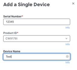 Serial Number and PID Requirement when adding device
Bulk device addition through CSV:
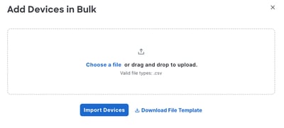 Bulk Import Option
2.2 APs connect via network: APs that are not pre-added to PnP. After the AP is connected to a switch and powered on with factory default settings, the AP contacts the PnP server on Catalyst Center, appear on the Provision -> Plug and Play page, and be ready to claim.
There are two deployment use cases for onboarding a new AP based on which network deployment you have configured on Catalyst Center .
- Intent based Network deployment - Go to AP onboarding with site assignment Use case (Intent-based Network Deployment).
- Non-Intent Based Network deployment - Go to AP onboarding without site assignment use case(non-intent based network deployments like Assurance, Per-Device Configuration).
AP onboarding with site assignment Use case (Intent-based Network Deployment)
This use case is suitable for customers whose wireless network has been designed and configured from Catalyst Center using intent-based automation and provisioned 9800-WLC with managed locations.

Note: If you want to configure AP location same as site location, enable the AP PnP location check box under System > Settings > PnP AP Location -Redirection details shown on page.
1 : PnP page is available in Provision->Plug and Play :Select single AP/multiple APs for claiming
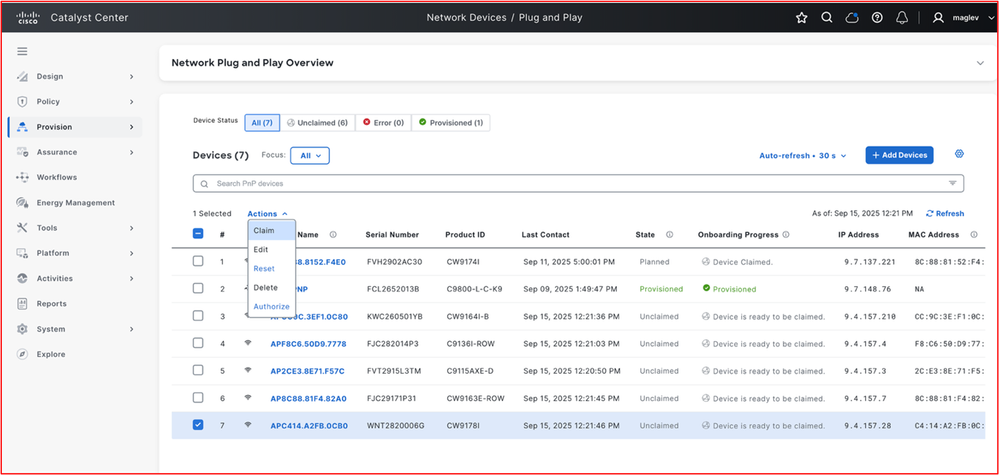 PnP Overview Page (Claim/Edit/Reset/Delete/Authorize)
2 Assign the AP to the floor where you want to claim the AP
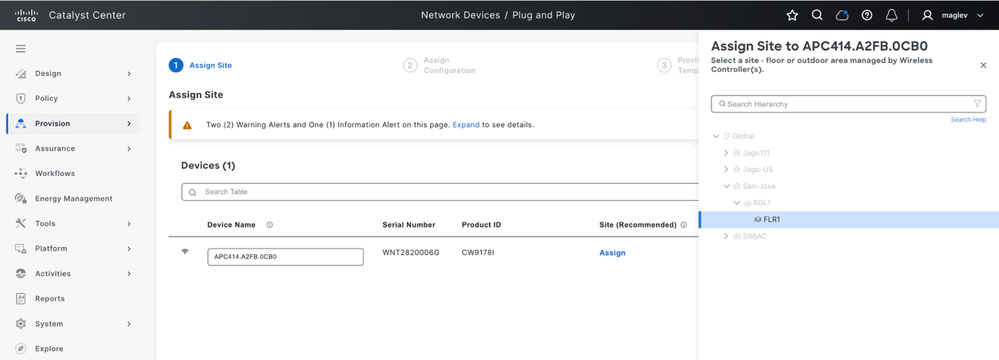 Assign to a site
3 Assign the RF profile for AP
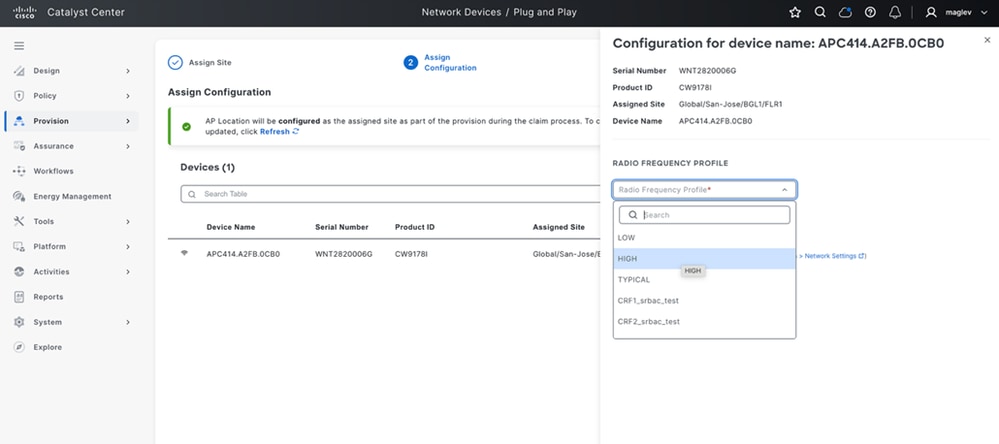 Assign RF Profile
4 if user not enabled the AP PnP location flag in system setting and want to configure AP location same as site location, enable the AP PnP location check box under System -> Settings -> PnP AP Location -Redirection details shown on page [one time enable]
After configuring, return to same RF assign page and refresh. If it’s enabled, it shows as green, if not enabled, it shows as orange.
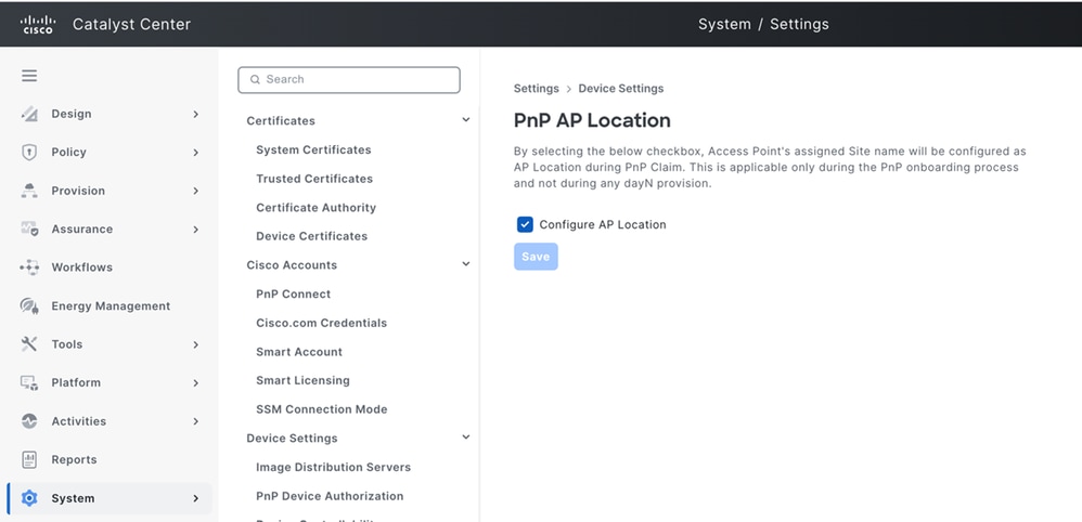 PnP AP Location
AP location enabled: AP location is configured as the assigned site as part of the provision during the claim process.
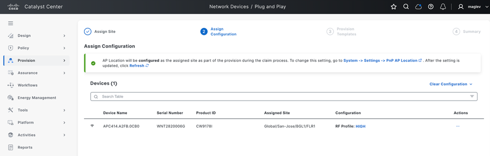 AP Location Enabled
5 Go to next page Provision template no action required and go to next page check the config preview and claim
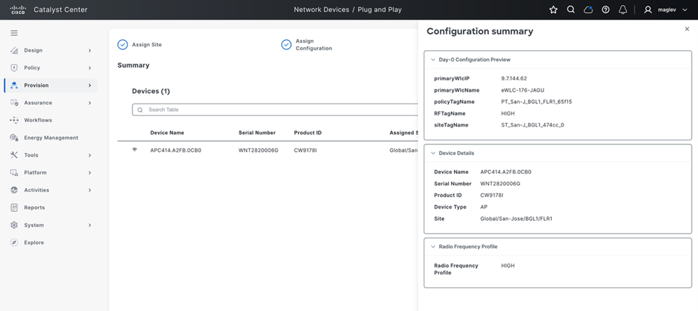 AP Configuration Summary
6 Once the AP is claimed, the config is pushed to the AP and it joins to particular controller managing the site and appears in Catalyst Center inventory with snmp-trap update and get auto provisioned with AP tags and AP location
AP Console logs:
[*09/15/2025 07:14:36.5440] PNP CONFIG - PRI WLC IP : 9.7.144.62
[*09/15/2025 07:14:36.5440] PNP CONFIG - PRI WLC NAME: eWLC-176-JAGU
[*09/15/2025 07:14:36.5440] PNP CONFIG - Policy Tag : PT_San-J_BGL1_FLR1_65f15
[*09/15/2025 07:14:36.5442] PNP CONFIG - Site Tag  :ST_San-J_BGL1_474cc_0
[*09/15/2025 07:14:36.5442] PNP CONFIG - RF Tag   : HIGH

show ap tag summary
APC414.A2FB.0CB0        c414.a2fb.0cb0   ST_SanJ_BGL1_474cc_0             PT_San-J_BGL1_FLR1_65f15          HIGH                   No               AP
7 After the AP is added to Inventory with SNMP-Trap, AP is marked as provisioned and PnP page and auto-provisioning of AP is done
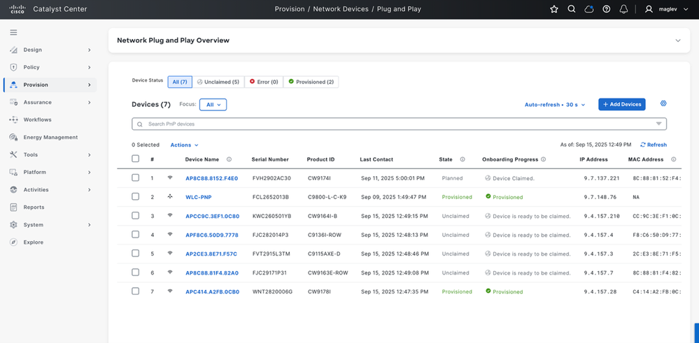 AP Onboarding Status
8 After AP added to the inventory, the Zero-touch provisioning triggers and provision AP’s tags and move AP to provision state
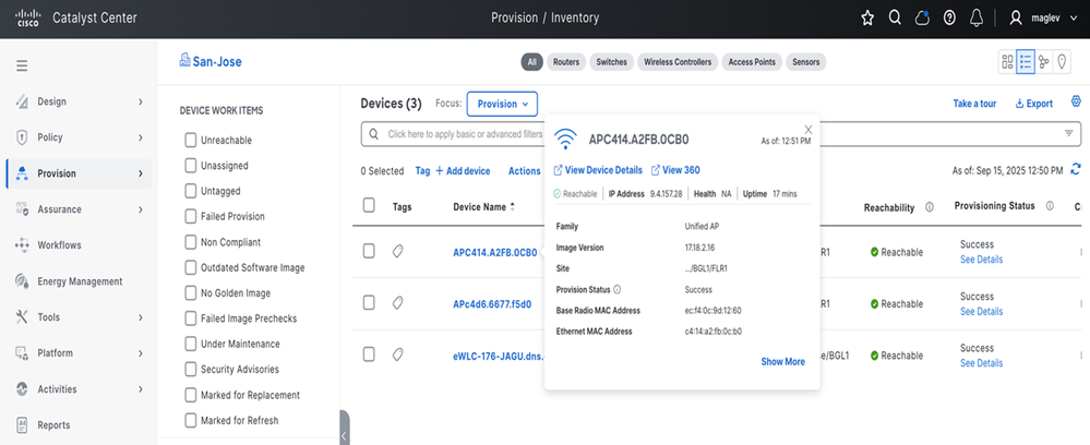 View AP Details
Location is set on AP based on site assignment. Run show ap summary on WLC CLI:
show ap summary
APC414.A2FB.0CB0                 4     CW9178I              c414.a2fb.0cb0 ecf4.0c9d.1260 US   -B   9.4.157.28    Registered   Global/San-Jose/BGL1/FLR1
AP onboarding without site assignment use case(non-intent based network deployments like Assurance, Per-Device Configuration)
1 Day-zero template creation in Catalyst Center
1.1 Go to Catalyst Center Tools > Template Hub.
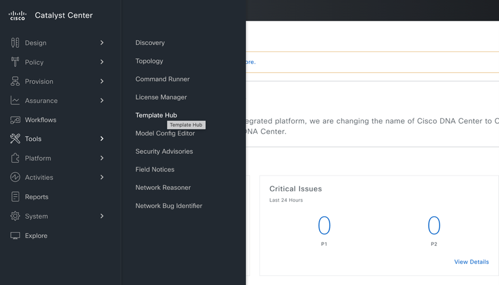 Template Hub
1.2: From the template section, New Project > Onboarding Configuration > Add > Select new template and create as shown, then continue.
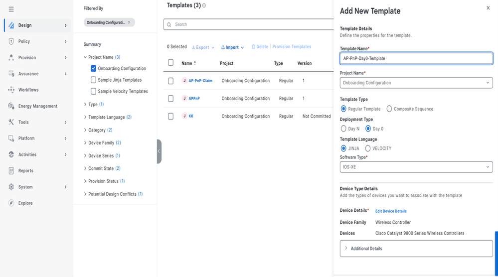 New Template
New template inputs.
- Enter these details:
- Template Name:** Enter a name for the template
- Project Name:** Onboarding Configuration
- Deployment Type:** Day0
- Template Language:** Jinja
- Software Type:** Cisco IOS XE
- Device Family:** Wireless Controller
- Device Model:** Cisco Catalyst 9800 Wireless Controller
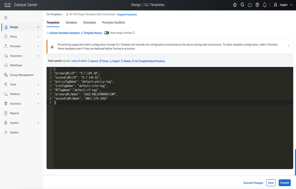
Example of AP day0 template :
{
"primaryWlcIP": "9.7.149.10",
"secondaryWlcIP": "9.7.144.62",
"policyTagName": "default-policy-tag",
"siteTagName": "default-site-tag",
"RFTagName": "default-rf-tag",
"primaryWlcName": "JAGU-EWLCAPWORKFLOW",
"secondaryWlcName": "eWLC-176-JAGU"
}
1.3 Add configuration details in template for pushing to AP during the claim of AP through template save and commit.
 Template Design Section
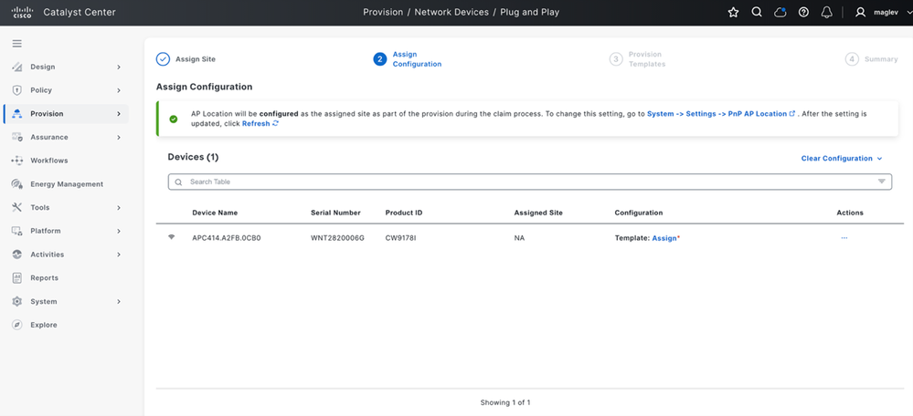
2 AP Claim without Site Assignment
2.1 Go to Provision > Plug and Play page and select the AP and claim
Note: You can select single/multiple APs and assign template.
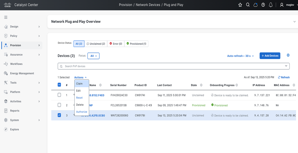 AP Claim without Site Assignment
2.2 In the next page, don’t select any in the site selection page and go to next page.
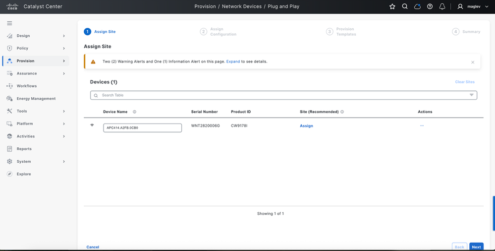 Location Assignment (Leave Unselected)
2.3 From the template selection page, select the template which is created.
 (1) Select Template
2.4 Click the template assign and from drop-down list, select the template created to push for AP and save
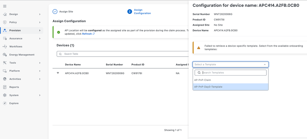 (2) Select Template
2.5 Click Next and preview the configuration to AP and claim
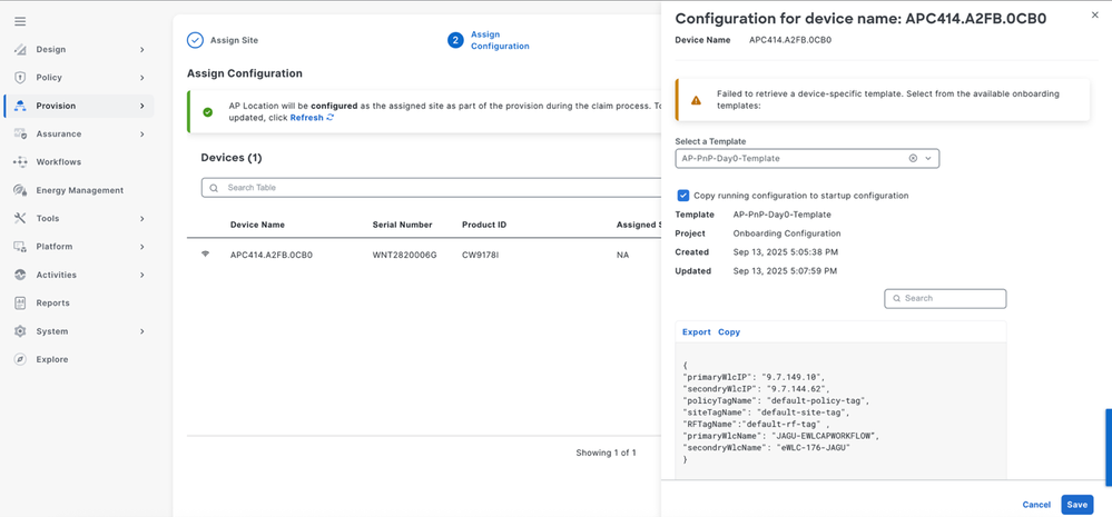 (3) Select Template Configuration Preview
2.6 After claim, the configuration is pushed to AP and AP joins the respective controller. It is displayed in the inventory
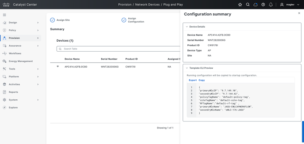 (4) Configuration Summary
Verification
After joining the wireless controller, the AP is displayed in the inventory based on this use case:
- Use case1-Assurance deployment # New AP claimed to the wireless controller which is added in Catalyst Center with site only assignment, new onboarded AP appears in the inventory with snmp-trap sync. After the AP appears, inventory is ready to be managed from Catalyst Center.
- Use case2-Per-device # New AP claimed to the wireless controller which is added in Catalyst Center without site assignment, new onboarded AP is not shown in the inventory until the `1`sync. After the AP appears in the inventory, it is ready to be managed from Catalyst Center.
Verify on the wireless controller:
show ap tag summary
show ap summary - Check the PnP page after adding AP to inventory, must be marked as Provisioned.
- For this, navigate to Provision > Network Devices > Plug and Play on Catalyst Center GUI.
AP Onboarding Troubleshooting
Pre-checks
- Ensure DHCP Option 43 or DNS is configured correctly so the AP can discover the PnP server.
- Verify that the AP has reachability to Catalyst Center using ping, traceroute, and basic network connectivity checks.
- Check whether the AP appears on the PnP page without any errors.
- PnP Claim Validation
- When the AP is visible on the PnP page, verify the device details before claim.
- When the user claims the AP, verify the preview details.
- Verify the claim status after the claim is submitted.
- Once the AP claim is completed, verify that the AP progresses correctly in the onboarding workflow.
- Wireless Controller Validation
- On the wireless controller, verify AP join status using:show ap summary
show wireless stats ap join summary- If the AP does not join the controller, identify the join failure reason and retry onboarding after performing an AP factory reset, if required.
- If the AP is claimed and joined to the eWLC, and the PnP workflow executed status is seen, but the AP is still not visible in Catalyst Center Inventory, check inventory-service, trap processing, and inventory sync.
Best Practices
Avoid running provisioning activities on the WLC that is involved in onboarding new APs.
Concurrent provisioning activities can trigger inventory sync, which can result in backlog or queue delay.
Avoid manually triggering user-initiated re-sync requests on the WLC unless required for troubleshooting.
Common Failure Focus Areas
AP not visible in PnP: verify the AP discovery path, including DHCP Option 43 or DNS.
AP claim fails: check onboarding-service logs.
AP claimed but not joined to WLC: check controller join status and join failure reason.
PnP workflow stuck after claim: if the AP has joined the WLC but is not visible in Inventory, check inventory-service, trap processing, and sync queue.
Provision triggered but configuration not applied as expected: check provisioning-service and network-programmer.
Recommended Outcome Validation
Confirm that the AP is successfully claimed in PnP.
Validate from the Catalyst Center PnP page that the AP is no longer in error state and the claim status is successful.
Confirm that the PnP workflow executed status is visible for the AP.
Confirm that the AP has joined the WLC.
show ap summary
show ap tag summary
show wireless stats ap join summary
show wlan summary
show wireless stats ap join summary
Verify that the AP is present in the joined AP list and there are no join failures.
Confirm that the AP is visible in Catalyst Center Inventory.
Validate from Catalyst Center Inventory that the AP appears under the expected site and is in reachable state.
Confirm that the onboarding or provisioning workflow completes successfully without errors.
From Catalyst Center, verify that the onboarding or provisioning task completes successfully.
Revision History
| Revision | Publish Date | Comments |
|---|---|---|
2.0 |
07-Jul-2026
|
Subtitle fixed |
1.0 |
10-Apr-2026
|
Initial Release |
 Feedback
Contact Cisco
- Open a Support Case

- (Requires a Cisco Service Contract)