Configure Catalyst Center Interface and Routing
Available Languages
Introduction
This document describes the design and configuration of network settings on the Cisco Catalyst Center appliance.
Prerequisites
Components Used
- Catalyst Center Version 2.3.5.5
The information in this document was created from the devices in a specific lab environment. All of the devices used in this document started with a cleared (default) configuration. If your network is live, ensure that you understand the potential impact of any command.
Background Information
The physical appliances provide four routed interfaces, each with one primary and one secondary physical network adapter. The physical location of these network adapters varies by appliance model, however, the logical configuration is the same. The virtual appliance OVA creates only one virtual network adapter, but a second can be added if needed. The reason for providing multiple adapters is to provide across a variety of network architectures. The flexibility to allow bi-directional communication between the appliance, the network devices it manages and/or monitors, the system administrators who need access to the solution, external integrations, and necessary cloud services. First, this document covers the interfaces and their intended use.
Interfaces
Enterprise (10G required)
The Enterprise interface is a ten-gigabit port on the physical appliance and is mapped to the first virtual adapter in the virtual appliance. It is meant to be the primary interface used to communicate with your devices, and in many deployments, can be the only interface used for all network communications.
Cluster (10G required, VA internal)
The Cluster interface is also a ten-gigabit port on the physical appliance, however, on the virtual appliance this is not mapped to any virtual adapter. It is used only for communication between Catalyst Center appliances in an HA cluster. This must be assigned an IP address from a subnet which is otherwise unused in the network. It is required to have this port connected with an IP configured during installation.
Management (1G/10G optional)
The Management interface is a one-gigabit port on the primary network adapter, and a ten-gigabit port on the secondary adapter. If a second virtual adapter is added to a virtual appliance, it is mapped to the Management interface. Some environments have strict network boundaries requiring the Enterprise interface to be placed in a secured network to manage your inventory, which causes difficulty for the Catalyst Center admins and users to access it. The Management interface provides these customers the ability to configure a second reachable IP address.
Internet/Cloud (1G/10G optional, VA not applicable)
The internet port is either a one-or ten-gigabit port on the physical appliances, like the Management port, but is not applicable for the virtual appliance. In many environments, access to the internet or other external services are restricted to only certain networks such as a DMZ. The internet or Cloud interface can be used for this connection.
Each of these interfaces can be configured in the Maglev Configuration Wizard with an IP address, Subnet Mask, a Default Gateway, DNS Servers, and one or more Static Routes. Only one interface can be configured with a Default Gateway and DNS Server, however, with any remaining interfaces, only utilizing Static Routes and the Cluster interface having no routes at all.
Configure
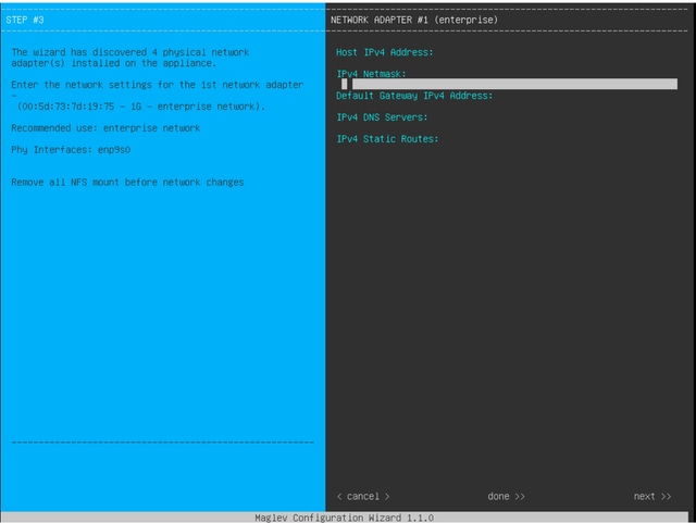 MAGLEV Configuration Wizard
The Maglev configuration wizard is accessible either during the initial installation, or by later connecting to the CIMC KVM and running the sudo maglev-config updatecommand. However, there are certain settings that cannot be altered after installation, as documented in the Install and Upgrades Guide.
In addition to the previously mentioned fields, you can configure Virtual IP addresses (or VIPs) for each interface that is configured with an IP. While the VIP configuration is optional for a single-node deployment, it is required for deploying a three node cluster.
The configurations control the way the appliance initiates connections (outbound routing) and how devices are configured to initiate their own connections with Catalyst Center (inbound routing).
Outbound Routing
Outbound routing, applies to all network communications initiated by the appliance and it is straightforward. The connected subnets, static routes, and default gateway settings from all interfaces configured in the wizard are placed into a shared routing table. When an outbound connection is created, the destination IP is looked up in this routing table to identify the egress interface and next-hop router. The source IP address is the local IP configured on the interface itself, not the VIP.

Note: This applies to all traffic (including DNS and NTP servers) regardless of which interfaces these servers are configured on in the wizard.
Inbound Routing
Inbound routing is configured on managed devices to control how they initiate connections towards the Catalyst Center. Devices and clients must access the Catalyst Center over the same ingress interface that the outbound routing table points to for their IP address. If (for example) a client attempts to connect to the Enterprise interface while the routing table for the client IP address points to the Management interface, the traffic is dropped.
Therefore, the system uses an outbound routing lookup for each inventory device's management IP to identify the correct interface, and configures the device to use the VIP of that interface for connecting to Catalyst Center. If no VIPs are configured (in a single-node installation), then the interface's local IP is used instead. In an FQDN-only certificate deployment, the cluster FQDN is configured on devices. In that case, the DNS architecture must ensure the correct interface VIP or IP is resolved by the client.
For Disaster Recovery deployments, the Disaster Recovery VIP is always configured if present. If there is no Disaster Recovery VIP configured, the VIP of the current Active cluster is configured.
Based on this information, to determine which interfaces are required in your environment and how to configure their routes, review these bullets:
- Determine which of your available IP networks has access to the internet and other external services.
- Determine which IP network has access to the devices you are managing.
- Verify which IP network your administrators is able to access.
- If all three (3) of these roles can be accomplished from a single IP network, then you only need to use the Enterprise port with a default gateway.
- If two (2) of these roles must be carried out on different networks, use the Enterprise port and either one of the Management or internet ports.
- One port has the default gateway assigned, while the other utilizes static routes.
- If each role requires its own IP network to operate, then all three (3) of the Enterprise, Management, and Internet ports are used.
- The default gateway is assigned to the Internet port.
- Static routes to your Administrator networks must be configured on the Management port.
- Static routes to all device management networks must be configured on the Enterprise port.
Revision History
| Revision | Publish Date | Comments |
|---|---|---|
2.0 |
09-Jul-2026
|
Updated spelling, grammar, inserted lines to separate sections for readability, and CCW alerts. |
1.0 |
23-Jul-2024
|
Initial Release |

 Feedback
Contact Cisco
- Open a Support Case

- (Requires a Cisco Service Contract)