Introduction
This document describes the configuration of route filtering and aggregation for MP-BGP redistribution in a Cisco ACI environment.
Concept
In Cisco ACI version 5.2(4) and later, you now have the capability for route filtering and aggregation to control routes from the L3-Out of BL to the fabric, allowing for more precise route management within the given VRF. This enhancement provides better control and optimization of route propagation within the ACI fabric.
Prerequisites
Basic understanding of ACI, L3out and BGP.
In this document, L3out is using the BGP protocol that is set up between the External Device and Border Leaf.
Some of the useful terms are briefly explained:
L3out (Layer 3 Out): The configuration object that enables Layer 3 connectivity to external networks. It defines how the ACI fabric connects to external routers.
Border Leaf (BL): switches that connect the ACI fabric to external networks.
Compute Leaf (CL): switches that connect the ACI fabric to compute nodes (servers).
MP-BGP (Multi-Protocol BGP): MP-BGP in Cisco ACI is an extension of the Border Gateway Protocol (BGP) that enables the support of multiple address families, such as IPv4, IPv6, and VPN, within a single BGP session. This extension allows for the seamless integration and management of diverse network environments, enabling efficient routing of different types of traffic across the ACI fabric while maintaining scalability and flexibility in the network architecture.
Route Filtering: It is used to control which routes are advertised to or accepted by other devices or routing protocols. By specifying criteria for routes to be included or excluded, route filtering helps manage the flow of routing information within the network, ensuring that only desired routes are propagated or received, thereby enhancing network security, efficiency, and stability.
Route Aggregation: The process of combining multiple IP prefixes into a single, broader prefix to streamline and optimize routing efficiency. This technique reduces the size of routing tables by summarizing routes, minimizing the number of entries that routers need to manage, and improving overall network performance by decreasing the complexity of route management and propagation.
Route Map: A set of configurable rules designed to control and manipulate routing information during the redistribution process between different routing protocols or devices. These rules allow network administrators to filter, modify, and manage which routes are advertised or accepted within the fabric, providing granular control over traffic flow and ensuring that only the desired routing information is propagated throughout the network.
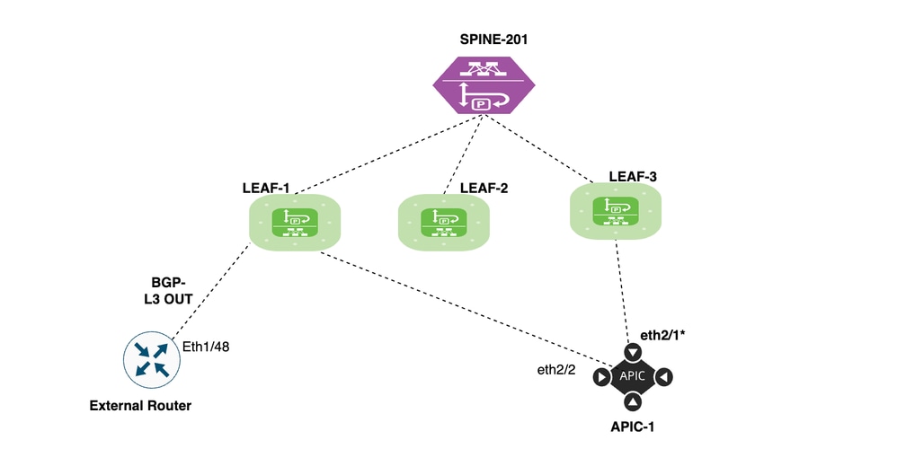
Setup and Topology
- Three leafs - LEAF-1,LEAF-2 and LEAF-3 of Model C93180YC-FX
- Spine : Spine1
- Border Leaf(BL): Leaf1
- L3out is configured on BL-Leaf1 -
Protocol: Border gateway Protocol (BGP)
BGP neighbor IP address 172.16.12.2/24
- Local AS- 65003,Remote AS- 100
Scenarios
We explore two scenarios to control the route advertisement from Border Leaf, where L3out is deployed towards the fabric.
1. Route filtering of specific routes from border leaf to fabric
2. Route aggregation of routes from border leaf to fabric
Configuration of Scenario One (Route filtering of specific routes from border leaf to fabric).
L3out is configured between the External router and Border Leaf (Leaf1) via the BGP protocol.
BGP neighborship between BL (leaf1) and external device is UP:
bgl-aci11-leaf1# show bgp ipv4 unicast summary vrf Tn_Route_Filtering:VRF_Route_Filtering
BGP summary information for VRF Tn_Route_Filtering:VRF_Route_Filtering, address family IPv4 Unicast
BGP router identifier 10.1.1.1, local AS number 65003
BGP table version is 14, IPv4 Unicast config peers 1, capable peers 1
7 network entries and 7 paths using 1456 bytes of memory
BGP attribute entries [4/704], BGP AS path entries [0/0]
BGP community entries [0/0], BGP clusterlist entries [1/4]

Neighbor V AS MsgRcvd MsgSent TblVer InQ OutQ Up/Down State/PfxRcd
172.16.12.1 4 100 456 457 14 0 0 07:31:35 3

bgl-aci11-leaf1#
There are three prefixes advertised, from external device to ACI .
Advertised Prefix List from External Routers:
192.168.1.0/24
192.168.2.0/24
192.168.3.0/24
BL leaf (Leaf1) on which all three prefixes are received.
bgl-aci11-leaf1# show ip route bgp vrf Tn_Route_Filtering:VRF_Route_Filtering
IP Route Table for VRF "Tn_Route_Filtering:VRF_Route_Filtering"
'*' denotes best ucast next-hop
'**' denotes best mcast next-hop
'[x/y]' denotes [preference/metric]
'%<string>' in via output denotes VRF <string>

192.168.1.0/24, ubest/mbest: 1/0
*via 172.16.12.1%Tn_Route_Filtering:VRF_Route_Filtering, [20/0], 07:35:35, bgp-65003, external, tag 100
192.168.2.0/24, ubest/mbest: 1/0
*via 172.16.12.1%Tn_Route_Filtering:VRF_Route_Filtering, [20/0], 07:35:35, bgp-65003, external, tag 100
192.168.3.0/24, ubest/mbest: 1/0
*via 172.16.12.1%Tn_Route_Filtering:VRF_Route_Filtering, [20/0], 07:35:35, bgp-65003, external, tag 100
bgl-aci11-leaf1#
By default, all routes received into Border leaf (Leaf1) from L3out are advertised to compute leaf (Leaf2 and Leaf3) via MP-BGP hence, we see all three prefixes in Compute leaf.
bgl-aci11-leaf2# show ip route bgp vrf Tn_Route_Filtering:VRF_Route_Filtering
IP Route Table for VRF "Tn_Route_Filtering:VRF_Route_Filtering"
'*' denotes best ucast next-hop
'**' denotes best mcast next-hop
'[x/y]' denotes [preference/metric]
'%<string>' in via output denotes VRF <string>

10.1.1.1/32, ubest/mbest: 1/0
*via 10.0.232.64%overlay-1, [1/0], 07:01:12, bgp-65003, internal, tag 65003
192.168.1.0/24, ubest/mbest: 1/0
*via 10.0.232.64%overlay-1, [200/0], 00:02:10, bgp-65003, internal, tag 100
192.168.2.0/24, ubest/mbest: 1/0
*via 10.0.232.64%overlay-1, [200/0], 00:02:10, bgp-65003, internal, tag 100
192.168.3.0/24, ubest/mbest: 1/0
*via 10.0.232.64%overlay-1, [200/0], 07:01:12, bgp-65003, internal, tag 100
172.16.12.0/24, ubest/mbest: 1/0
*via 10.0.232.64%overlay-1, [200/0], 07:01:12, bgp-65003, internal, tag 65003
bgl-aci11-leaf2#
Implementation Steps:
Step 1. Log in to APIC.
Access APIC using admin credentials.
Step 2. Select the VRF.
Navigate to Tenants > Tn_Route_Filtering > Networking > VRFs > VRF_Route_Filtering >Route Control >Infra-VRF Import Route Control Policy
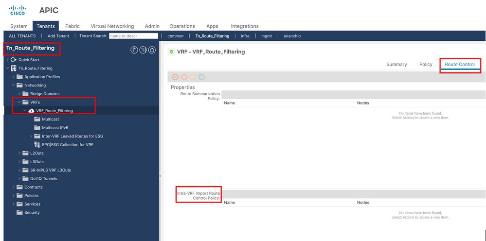
Step 3. Create the Intra-VRF Import Route Control Policy.
Navigate to Route Control >Infra-VRF Import Route Control Policy
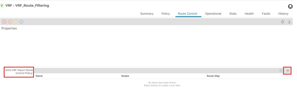
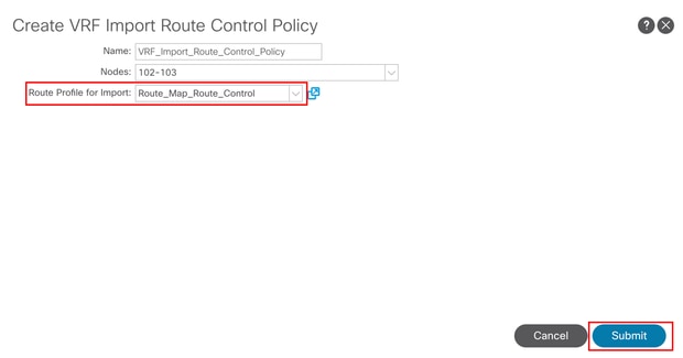
Step 4. Create VRF Import Route Control Policy.
Click + (plus) icon to create VRF Import Route Control Policy.
Provide a name and node for the VRF.
Name: In this document, the policy name is VRF_Import_Route_Control_policy.
Nodes: The node on which you want to control the route advertisement in this document is compute Leaf (Leaf2 and Leaf3)
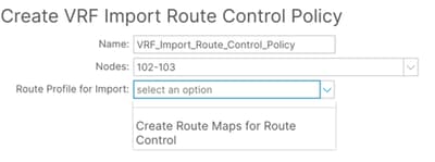
Step 5. Create Route Maps for Route Control
Click on "Create Route Maps for Route Control".
Provide a name and description for Route Maps for Route Control.
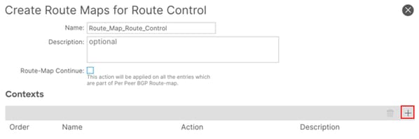
Step 6. Configure the Contexts.
To Complete the Route Map configuration, you need to configure the context.
Click on the + (plus) icon to create a new context.
Provide a name for the route control context and description.
Define the Action either Deny or Permit.
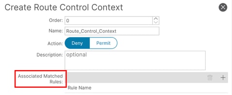
Step 7. Create the Associated Matched Rules
To Complete the Route Control Context, you need to configure the Associated matched Rules.
Click on “+“ sign under Associated matched Rule
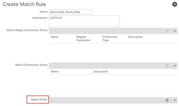
select "Create Match Rule for Route Map"
Give a name to match rule.
Step 8. Add the Match Prefix
Now you configure the Match Rule to complete the Associated Matched Rules.
Name: Give a name and description to Match Rule.
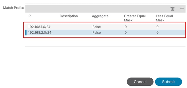
Match Prefix : Enter the IP prefix you want to match
Step 9. Add the Match Prefix
Click + (plus sign) to add a new Prefix entry which we need to deny.
IP Address : Enter the destination IP address or prefix you want to match and add the description.
Aggregate Tab : Used to configure aggregate route policies.
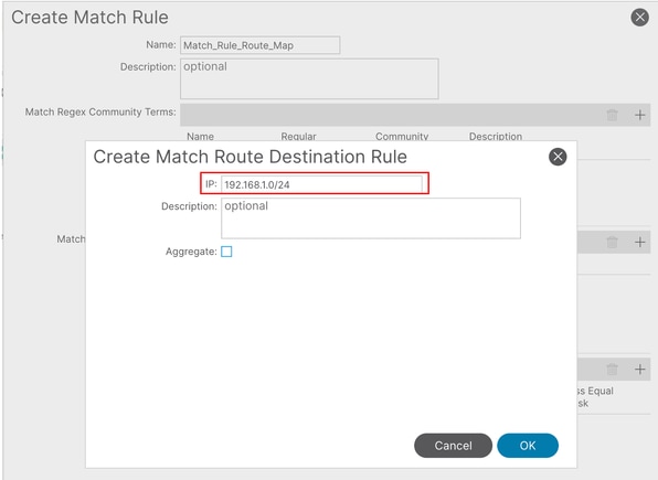
In this example we need to deny 192.168.1.0/24 and 192.168.2.0/24 so we add both prefix.
Then click on submit to create the Match Rule.
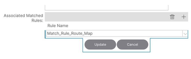
Step 10. Now select the Created Associated Matched rule and Update it.
Step 11. Create the rule for route-map
Now we configure the set rule for route-map.
Click on set rule Tab.
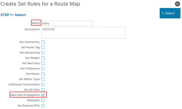
Select the "Create set Rule for a Route Map".
Enter the name of set rule and enable the check box of Next Hope Propagation.
Click on Finish Tab.
In this document the rule name is "Deny” and "Next Hop Propagation" is selected.
Step 12. Submit the Route Control Context
Click on Submit tab to create the Route Control Context.
Then click on Submit tab to create the Route Control Profile.
Now select the Route profile for import from drop down list and Click on Submit.
Verification and troubleshooting
You can now check the routes on your compute leaf ,routes which are filtered are not present in routing table.
bgl-aci11-leaf2# show ip route bgp vrf Tn_Route_Filtering:VRF_Route_Filtering
IP Route Table for VRF "Tn_Route_Filtering:VRF_Route_Filtering"
'*' denotes best ucast next-hop
'**' denotes best mcast next-hop
'[x/y]' denotes [preference/metric]
'%<string>' in via output denotes VRF <string>

10.1.1.1/32, ubest/mbest: 1/0
*via 10.0.232.64%overlay-1, [1/0], 07:30:37, bgp-65003, internal, tag 65003
192.168.3.0/24, ubest/mbest: 1/0
*via 10.0.232.64%overlay-1, [200/0], 07:30:37, bgp-65003, internal, tag 100
172.16.12.0/24, ubest/mbest: 1/0
*via 10.0.232.64%overlay-1, [200/0], 07:30:37, bgp-65003, internal, tag 65003
bgl-aci11-leaf2#
 Feedback