Troubleshoot ACI Policy-Based Redirect
Available Languages
Download Options
Bias-Free Language
The documentation set for this product strives to use bias-free language. For the purposes of this documentation set, bias-free is defined as language that does not imply discrimination based on age, disability, gender, racial identity, ethnic identity, sexual orientation, socioeconomic status, and intersectionality. Exceptions may be present in the documentation due to language that is hardcoded in the user interfaces of the product software, language used based on RFP documentation, or language that is used by a referenced third-party product. Learn more about how Cisco is using Inclusive Language.
Contents
Introduction
This document describes steps to understand and troubleshoot an ACI Policy-Based Redirect (PBR) scenario.
Background Information
The material from this document was extracted from the Troubleshooting Cisco Application Centric Infrastructure, Second Edition book, specifically the Policy-Based Redirect - Overview, Policy-Based Redirect - Service Graph Deployment, Policy-Based Redirect - Forwarding andPolicy-Based Redirect - Other traffic flow examples chapters.
Policy-Based Redirect Overview
This chapter explains troubleshooting for unmanaged mode Service Graph with Policy-Based Redirect (PBR).
The following are typical troubleshooting steps. This chapter explains how to verify steps 2 and 3 which are specific to PBR. For steps 1 and 4, please refer to chapters: "Intra-Fabric forwarding", "External forwarding", and "Security policies".
- Check the traffic works without PBR Service Graph:
- Consumer and provider endpoints are learned.
- Consumer and provider endpoints can communicate.
- Check Service Graph is deployed:
- Deployed Graph Instances have no fault.
- VLANs and class IDs for service node are deployed.
- Service node endpoints are learned.
- Check the forwarding path:
- Check policy is programmed on the leaf nodes.
- Capture the traffic on the service node to confirm if traffic is redirected.
- Capture the traffic on the ACI leaf to confirm if traffic comes back to the ACI fabric after PBR.
- Check the traffic arrives on the consumer and provider endpoint, and that the endpoint generates the return traffic.
This document doesn’t cover design or configuration options. For that information, please refer to the "ACI PBR White Paper" on Cisco.com
In this chapter, service node and service leaf imply the following:
- Service node — an external node to which PBR is redirecting the traffic, such as a firewall or load balancer.
- Service leaf — an ACI leaf that is connected to a service node.
Troubleshooting Service Graph Deployment
This chapter explains a troubleshooting example where a Service Graph is not deployed.
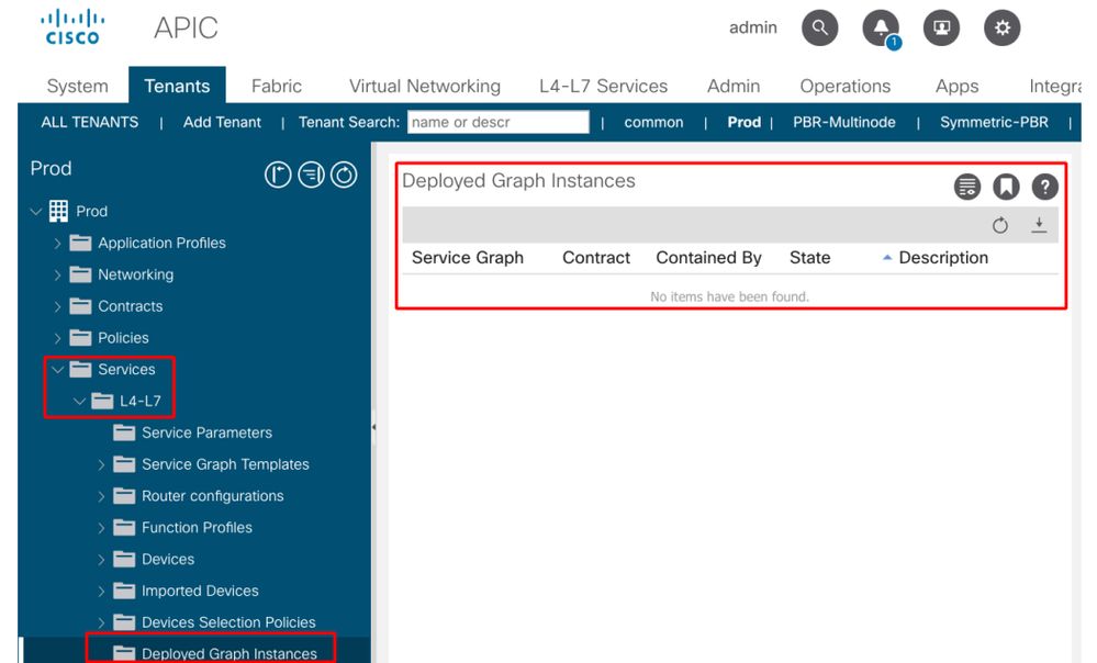
After a Service Graph policy is defined and applied to a contract subject, there should be a deployed graph instance appearing on the ACI GUI. The figure below shows the troubleshooting scenario where the Service Graph does not appear as deployed.
Service Graph is not shown as a Deployed Graph Instance.
1. Check configuration steps and fault
The first step of troubleshooting is to check the necessary components have been configured without any fault. The assumption is that general configurations below are already done:
- VRF and BDs for consumer EPG, provider EPG and service node
- The consumer and provider EPG.
- The contract and filters.
It’s worth mentioning that an EPG for the service node is not needed to be created manually. It will be created through Service Graph deployment.
Service Graph with PBR configuration steps are the following:
- Create the L4-L7 Device (Logical Device).
- Create the Service Graph.
- Create the PBR policy.
- Create the Device Selection policy.
- Associate the Service Graph with the contract subject.
2. Check Service Graph deployment in the UI
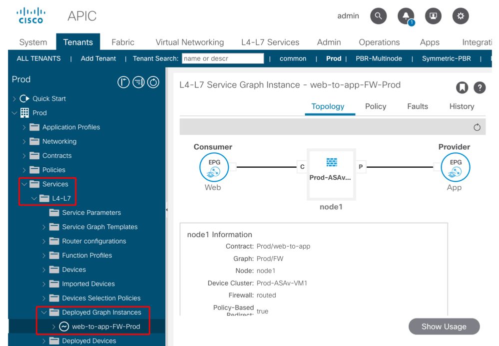
After a Service Graph is associated to the contract subject, a deployed graph instance should show up for each contract with Service Graph (figure below).
The location is 'Tenant > Services > L4-L7 > Deployed Graph Instances'
Deployed Graph Instance
If a Deployed Graph Instance does not show up, there is something wrong with the contract configuration. Major reasons can be:
- The contract doesn't have a consumer or provider EPG.
- The contract subject doesn't have any filter.
- The contract scope is VRF even though it's for inter-VRF or inter-tenant EPG communication.
If Service Graph instantiation fails, faults are raised in the Deployed Graph Instance, which means there is something wrong with the Service Graph configuration. Typical faults caused by configuration are the following:
F1690: Configuration is invalid due to ID allocation failure
This fault indicates that the encapsulated VLAN for the service node is not available. For example, there is no available dynamic VLAN in the VLAN pool associated to the VMM domain used in the Logical Device.
Resolution: Check the VLAN pool in the domain used for the Logical Device. Check encapsulated VLAN in the Logical Device interface if it's in a physical domain. The locations are 'Tenant > Services > L4-L7 > Devices and Fabric >Access Policies > Pools > VLAN'.
F1690: Configuration is invalid due to no device context found for LDev
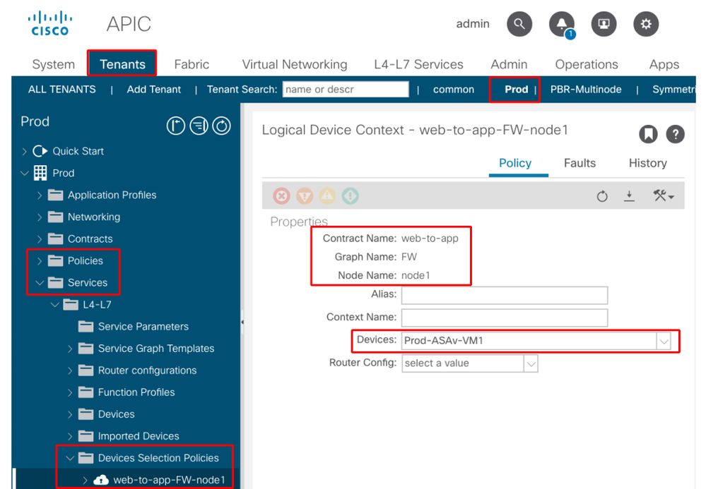
This fault indicates that the Logical Device can't be found for the Service Graph rendering. For example, there is no Device Selection Policy matched for the contract with the Service Graph.
Resolution: Check the Device Selection Policy is defined. Device Selection Policy provides a selection criterion for a service device and its connectors. The criteria are based on a contract name, a Service Graph name, and a node name in the Service Graph. The location is 'Tenant > Services > L4-L7 > Device Selection Policy'.
Check Device Selection Policy
F1690: Configuration is invalid due to no cluster interface found
This fault indicates that the cluster interface for the service node can't be found. For example, the cluster interface is not specified in Device Selection Policy.
Resolution: Check the cluster interface is specified in Device Selection policy and connector name is correct (Figure below).
F1690: Configuration is invalid due to no BD found
This fault indicates that the BD for the service node can't be found. For example, the BD is not specified in Device Selection Policy.
Resolution: Check BD is specified in Device Selection policy and connector name is correct (Figure below).
F1690: Configuration is invalid due to invalid service redirect policy
This fault indicates that the PBR policy is not selected even though redirect is enabled on the service function in the Service Graph.
Resolution: Select PBR policy in the Device Selection Policy (Figure below).
Logical interface configuration in Device Selection Policy

Troubleshooting PBR Forwarding
This chapter explains the troubleshooting steps for the PBR forwarding path.
1. Check VLANs are deployed and endpoints are learned on the leaf node
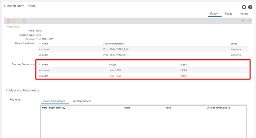
Once a Service Graph is successfully deployed without any fault, EPGs and BDs for a service node get created. The figure below shows where to find the encapsulated VLAN IDs and class IDs of service node interfaces (Service EPGs). In this example, the consumer side of a firewall is class ID 16386 with VLAN encap 1000 and the provider side of a firewall is class ID 49157 with VLAN encap 1102.
The location is 'Tenant > Services > L4-L7 > Deployed Graph instances > Function Nodes'.
Service node
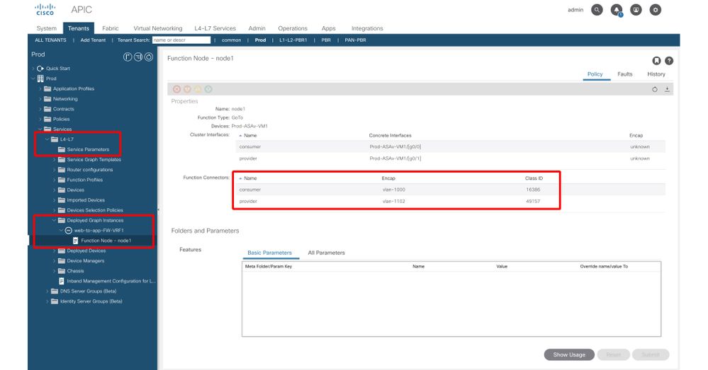
Service node interface class ID
These VLANs are deployed on the service leaf node interfaces where the service nodes are connected. VLAN deployment and endpoint learning status can be checked by using 'show vlan extended' and 'show endpoint' on the service leaf node CLI.
Pod1-Leaf1# show endpoint vrf Prod:VRF1
Legend:
s - arp              H - vtep             V - vpc-attached     p - peer-aged
R - peer-attached-rl B - bounce           S - static           M - span
D - bounce-to-proxy  O - peer-attached    a - local-aged       m - svc-mgr
L - local            E - shared-service
+-----------------------------------+---------------+-----------------+--------------+-------------+
      VLAN/                           Encap           MAC Address       MAC Info/       Interface
      Domain                          VLAN            IP Address        IP Info
+-----------------------------------+---------------+-----------------+--------------+-------------+
53                                        vlan-1000    0050.56af.3c60 LV                        po1
Prod:VRF1                                 vlan-1000   192.168.101.100 LV                        po1
59                                        vlan-1102    0050.56af.1c44 LV                        po1
Prod:VRF1                                 vlan-1102   192.168.102.100 LV                        po1
If endpoint IPs of the service nodes are not learned as endpoints in ACI fabric, it’s most likely either a connectivity or configuration issue between the service leaf and service node. Please check the following statuses:
- The service node is connected to the correct leaf downlink port.
- If the service node is in a physical domain, the leaf static path end encap VLAN needs to be defined in the Logical Device.
- If the service node is in a VMM domain, please check the VMM domain is working and the port group created through Service Graph is attached to the service node VM correctly.
- The leaf downlink port connected to the service node or the hypervisor where the service node VM resides is UP.
- The service node has the correct VLAN and IP address.
- Intermediate switch between the service leaf and the service node has the correct VLAN configuration.
2. Check the expected traffic paths
If end-to-end traffic stops working once PBR is enabled, even though the service node endpoints are learned in ACI fabric, the next troubleshooting step is to check what the expected traffic paths are.
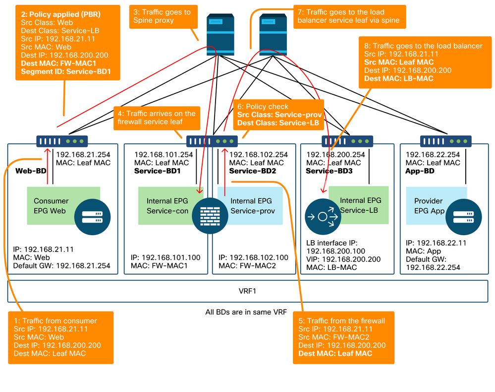
Figures 'PBR forwarding path example - consumer to provider' and 'PBR forwarding path example - provider to consumer' illustrate a forwarding path example of firewall insertion using PBR between a consumer endpoint and a provider endpoint. The assumption is that the endpoints are already learned on leaf nodes.
PBR forwarding path example - consumer to provider
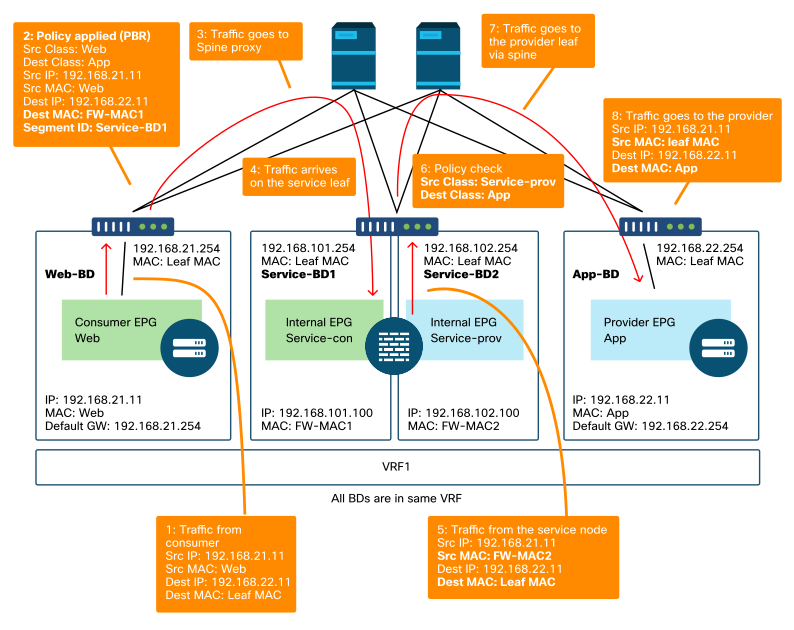
Note : Since source MAC is not changed to ACI leaf MAC, the PBR node must not use source MAC based forwarding if consumer endpoint and PBR node are not in the same BD
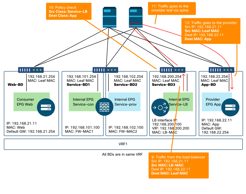
PBR forwarding path example - provider to consumer
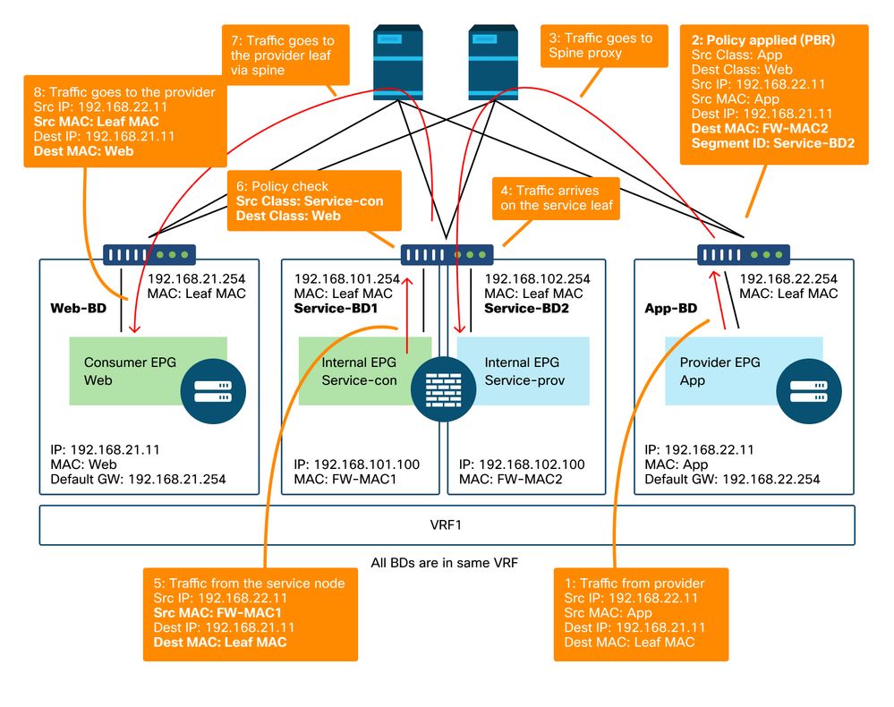
Note: It's worth mentioning that PBR policy is enforced on either consumer or provider leaf and what ACI PBR does is destination MAC rewrite as shown in figures 'PBR forwarding path example - consumer to provider' and 'PBR forwarding path example - provider to consumer'. Reaching the PBR destination MAC always uses a spine proxy, even if the source endpoint and PBR destination MAC are under the same leaf.
Though figures 'PBR forwarding path example - consumer to provider' and 'PBR forwarding path example - provider to consumer' show an example of where the traffic would be redirected, where policy is enforced depends on contract configuration and endpoint learning status. The table 'Where policy is enforced' summarizes where policy is enforced a single ACI site. Where policy is enforced in Multi-Site is different.
Where is policy enforced?
|
Scenario |
VRF enforcement mode |
Consumer |
Provider |
Policy enforced on |
|
Intra-VRF |
Ingress/egress |
EPG |
EPG |
· If destination endpoint is learned: ingress leaf* · If destination endpoint is not learned: egress leaf |
|
Ingress |
EPG |
L3Out EPG |
Consumer leaf (non-border leaf) |
|
|
Ingress |
L3Out EPG |
EPG |
Provider leaf (non-border leaf) |
|
|
Egress |
EPG |
L3Out EPG |
Border leaf -> non-border leaf traffic · If destination endpoint is learned: border leaf · If destination endpoint is not learned: non-border leaf Non-border leaf-> border leaf traffic · Border leaf |
|
|
Egress |
L3Out EPG |
EPG |
||
|
Ingress/egress |
L3Out EPG |
L3Out EPG |
Ingress leaf* |
|
|
Inter-VRF |
Ingress/egress |
EPG |
EPG |
Consumer leaf |
|
Ingress/egress |
EPG |
L3Out EPG |
Consumer leaf (Non-border leaf) |
|
|
Ingress/egress |
L3Out EPG |
EPG |
Ingress leaf* |
|
|
Ingress/egress |
L3Out EPG |
L3Out EPG |
Ingress leaf* |
*Policy enforcement is applied on the first leaf hit by the packet.
These are examples:
- If an external endpoint in L3Out EPG in VRF1 tries to access an endpoint in Web EPG in VRF1 and VRF1 is configured for ingress enforcement mode, traffic is redirected by the leaf where the endpoint in Web EPG resides, regardless of contract direction.
- If an endpoint in consumer Web EPG in VRF1 tries to access an endpoint in provider App EPG in VRF1, and the endpoints are learned on consumer and provider leaf nodes, traffic is redirected by the ingress leaf.
- If an endpoint in consumer Web EPG in VRF1 tries to access an endpoint in provider App EPG in VRF2, traffic is redirected by the consumer leaf where the consumer endpoint resides, regardless of the VRF enforcement mode.
3. Check if traffic is redirected to the service node
Once the expected forwarding path is clear, ELAM can be used to check whether traffic arrives on the switch nodes and check the forwarding decision on the switch nodes. Please refer to section "Tools" in the chapter "Intra-Fabric Forwarding" for instructions on how to use ELAM.
For example, to trace the traffic flow in the figure 'PBR forwarding path example - consumer to provider', these can be captured to confirm if consumer to provider traffic is redirected.
- Downlink port on consumer leaf to check 1 and 2 (Traffic arrives on the consumer leaf and PBR is enforced).
- Fabric port on spine nodes to check 3 (Traffic goes to spine proxy).
- Fabric port on service leaf to check 4 (Traffic arrives on the service leaf).
Then, these can be captured to confirm if traffic that comes back from the service node goes to the provider.
- Downlink port on the service leaf to check 5 and 6 (Traffic comes back from the service node and is permitted).
- Fabric port on spine nodes to check 7 (Traffic goes to provider leaf via spine).
- Fabric port on provider leaf to check 8 (Traffic arrives on the service leaf and goes to the provider endpoint).
Note: If consumer and service node are under the same leaf, specify an interface or source MAC in addition to source/destination IP to take ELAM to check 1 or 5 in figure 'PBR forwarding path example - consumer to provider' specifically because both use the same source IP and destination IP.
If the consumer to provider traffic is redirected to the service node but doesn't come back to the service leaf, please check the following as they are common mistakes:
- Service node routing table reaches the provider subnet.
- Service node security policy such as ACL permits the traffic.
If the traffic is redirected and arrives on the provider, please check the return traffic path from provider to consumer in a similar way.
4. Check the policies programmed on leaf nodes
If traffic is not forwarded or redirected accordingly, the next troubleshooting step is to check the policies programmed on the leaf nodes. This section shows zoning-rule and contract_parser as examples. For more detail of how to check zoning-rules, please refer to section "Tools" in chapter "Security Policies".
Note: The policies are programmed based on EPG deployment status on the leaf. The show command output in this section uses the leaf that has consumer EPG, provider EPG, and EPGs for the service node.
Use of the 'show zoning-rule' command
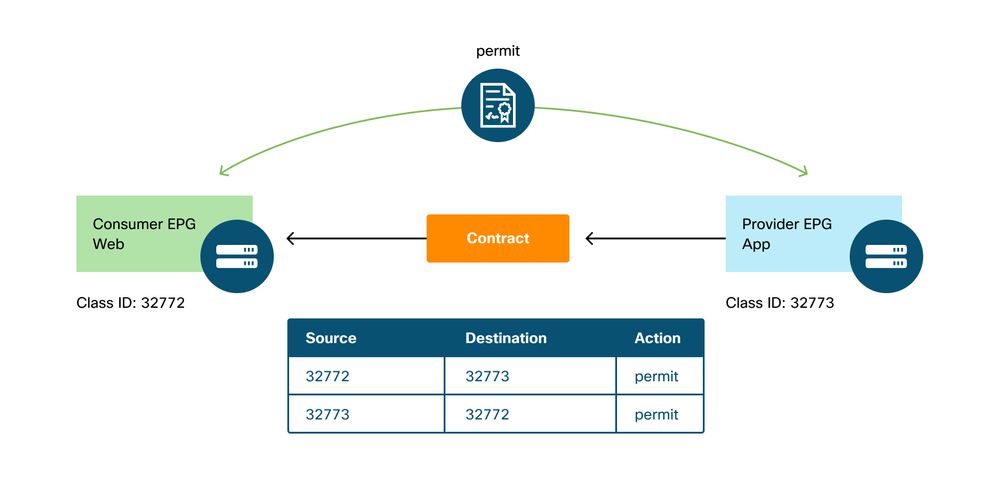
The figure and the 'show zoning-rule' output below describes the zoning-rules before Service Graph deployment.
VRF scope id can be found in 'Tenant > Networking > VRF'.
Pod1-Leaf1# show zoning-rule scope 2752513
+---------+--------+--------+----------+----------------+---------+---------+------------+----------+----------------------+
| Rule ID | SrcEPG | DstEPG | FilterID |      Dir       |  operSt |  Scope  |    Name    |  Action  |       Priority       |
+---------+--------+--------+----------+----------------+---------+---------+------------+----------+----------------------+
|   4237  | 32772  | 32773  |    8     |     bi-dir     | enabled | 2752513 | web-to-app |  permit  |    fully_qual(7)     |
|   4172  | 32773  | 32772  |    9     | uni-dir-ignore | enabled | 2752513 | web-to-app |  permit  |    fully_qual(7)     |
+---------+--------+--------+----------+----------------+---------+---------+------------+----------+----------------------+
Once the Service Graph is deployed, EPGs for the service node get created and policies are updated to redirect traffic between the consumer and the provider EPGs. The figure below and the 'show zoning-rule' output below describes the zoning-rules after Service Graph deployment. In this example, the traffic from pcTag 32772 (Web) to pcTag 32773 (App) is redirected to 'destgrp-27' (consumer side of the service node) and the traffic from pcTag 32773 (App) to pcTag 32772 (Web) is redirected to 'destgrp-28' (provider side of the service node).
Zoning-rules after Service Graph deployment
Pod1-Leaf1# show zoning-rule scope 2752513
+---------+--------+--------+----------+----------------+---------+---------+------+-------------------+----------------------+
| Rule ID | SrcEPG | DstEPG | FilterID |      Dir       |  operSt |  Scope  | Name |       Action      |       Priority       |
+---------+--------+--------+----------+----------------+---------+---------+------+-------------------+----------------------+
...
|   4213  | 16386  | 32772  |    9     |    uni-dir     | enabled | 2752513 |      |       permit      |    fully_qual(7)     |
|   4249  | 49157  | 32773  | default  |    uni-dir     | enabled | 2752513 |      |       permit      |    src_dst_any(9)    |
|   4237  | 32772  | 32773  |    8     |     bi-dir     | enabled | 2752513 |      | redir(destgrp-27) |    fully_qual(7)     |
|   4172  | 32773  | 32772  |    9     | uni-dir-ignore | enabled | 2752513 |      | redir(destgrp-28) |    fully_qual(7)     |
+---------+--------+--------+----------+----------------+---------+---------+------+-------------------+----------------------+
The destination information of each destgrp can be found by using the 'show service redir info' command.
Pod1-Leaf1# show service redir info
============================================================================================
LEGEND
TL: Threshold(Low)  |  TH: Threshold(High) |  HP: HashProfile  |  HG: HealthGrp  | BAC: Backup-Dest |  TRA: Tracking  | RES: Resiliency
============================================================================================
List of Dest Groups
GrpID Name            destination                                 HG-name           BAC  operSt     operStQual      TL   TH   HP   TRAC RES
===== ====            ===========                                 ==============    ===  =======    ============    ===  ===  ===  ===  ===
28    destgrp-28      dest-[192.168.102.100]-[vxlan-2752513]      Not attached      N    enabled    no-oper-grp     0    0    sym  no   no
27    destgrp-27      dest-[192.168.101.100]-[vxlan-2752513]      Not attached      N    enabled    no-oper-grp     0    0    sym  no   no

List of destinations
Name                                          bdVnid             vMac                    vrf         operSt     operStQual      HG-name
====                                          ======             ====                    ====        =====      =========       =======
dest-[192.168.102.100]-[vxlan-2752513]        vxlan-16023499     00:50:56:AF:1C:44       Prod:VRF1   enabled    no-oper-dest    Not attached
dest-[192.168.101.100]-[vxlan-2752513]        vxlan-16121792     00:50:56:AF:3C:60       Prod:VRF1   enabled    no-oper-dest    Not attached
...
If zoning-rules are programmed accordingly, but traffic is not redirected or forwarded accordingly, please check the following as they are common mistakes:
- Check if the source or destination class ID is resolved as expected by using ELAM. If not, please check what the wrong class ID is and the EPG derivation criteria such as path and encap VLAN.
- Even though source and destination class IDs are resolved accordingly, and PBR policy is applied but traffic doesn't arrive on the PBR node, please check IP, MAC, and VRF of the destgrp in the redir action ('show service redir info') are correct.
By default, permit rules for a consumer EPG to a service node (consumer side), and a provider EPG to a service node (provider side) are not programmed if PBR is enabled. Thus, a consumer or provider endpoint can't directly communicate to the service node by default. To permit this traffic, the Direct Connect option needs to be enabled. The use case is explained in section "Other traffic flow examples".
Use of contract_parser
The contract_parser tool can also help to verify the policies. C-consumer is the consumer side of the service node and C-provider is the provider side of the service node.
Pod1-Leaf1# contract_parser.py --vrf Prod:VRF1
Key:
[prio:RuleId] [vrf:{str}] action protocol src-epg [src-l4] dst-epg [dst-l4] [flags][contract:{str}] [hit=count]

[7:4213] [vrf:Prod:VRF1] permit ip tcp tn-Prod/G-Prod-ASAv-VM1ctxVRF1/C-consumer(16386) eq 80 tn-Prod/ap-app1/epg-Web(32772)  [contract:uni/tn-Prod/brc-web-to-app] [hit=0]
[7:4237] [vrf:Prod:VRF1] redir ip tcp tn-Prod/ap-app1/epg-Web(32772) tn-Prod/ap-app1/epg-App(32773) eq 80  [contract:uni/tn-Prod/brc-web-to-app] [hit=0]
                               destgrp-27 vrf:Prod:VRF1 ip:192.168.101.100 mac:00:50:56:AF:3C:60 bd:uni/tn-Prod/BD-Service-BD1
[7:4172] [vrf:Prod:VRF1] redir ip tcp tn-Prod/ap-app1/epg-App(32773) eq 80 tn-Prod/ap-app1/epg-Web(32772)  [contract:uni/tn-Prod/brc-web-to-app] [hit=0]
                               destgrp-28 vrf:Prod:VRF1 ip:192.168.102.100 mac:00:50:56:AF:1C:44 bd:uni/tn-Prod/BD-Service-BD2
[9:4249] [vrf:Prod:VRF1] permit any tn-Prod/G-Prod-ASAv-VM1ctxVRF1/C-provider(49157) tn-Prod/ap-app1/epg-App(32773) [contract:uni/tn-Prod/brc-web-to-app] [hit=15]
...
Other traffic flow examples
This section considers other common traffic flow examples to identify the desired flows for troubleshooting. For troubleshooting steps, please refer to the previous chapter in this section.
- Load balancer without SNAT:
- In this example, consumer EPG Web and provider EPG App have a contract with a load balancer Service Graph. Endpoints in App EPG are real servers associated to the VIP on the load balancer.
- PBR to load balancer is enabled for provider to consumer traffic direction.
- Firewall and load balancer without SNAT:
- In this example, consumer EPG Web and provider EPG App have a contract with a firewall and a load balancer Service Graph. Endpoints in App EPG are real servers associated with the VIP on load balancer.
- PBR to firewall is enabled for both directions.
- PBR to load balancer is enabled for provider to consumer traffic direction.
- Shared service (Inter-VRF contract):
- In this example, consumer EPG Web and provider EPG App have a contract with a firewall Service Graph. EPG Web and EPG App are in different VRFs.
- PBR to firewall is enabled for both directions.
- The firewall is in between VRFs.
1. Load balancer without SNAT
PBR can be deployed as bidirectional PBR or unidirectional PBR. One use case for unidirectional PBR is load balancer integration without source Network Address Translation (NAT). If load balancer performs source NAT, PBR is not required.
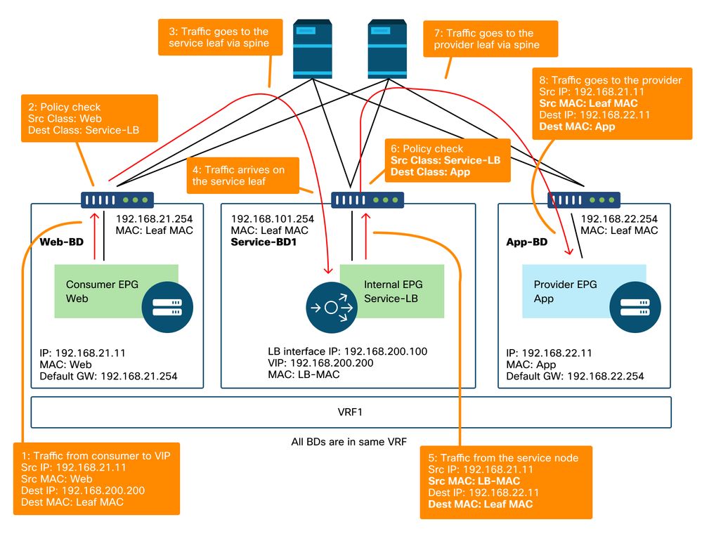
Traffic path example
The figure below illustrates an example of an incoming traffic flow from consumer EPG Web to provider EPG App with two connections: One is from an endpoint in the consumer EPG Web to the load balancer VIP, and the other is from the load balancer to an endpoint in the provider EPG App. Because the incoming traffic is destined to the VIP, the traffic will reach the load balancer without PBR if the VIP is reachable. The load balancer changes the destination IP to one of the endpoints in EPG App associated to the VIP but doesn't translate the source IP. Accordingly, traffic goes to the provider endpoint.
Load balancer without SNAT forwarding path example — consumer to VIP and load balancer to provider without PBR
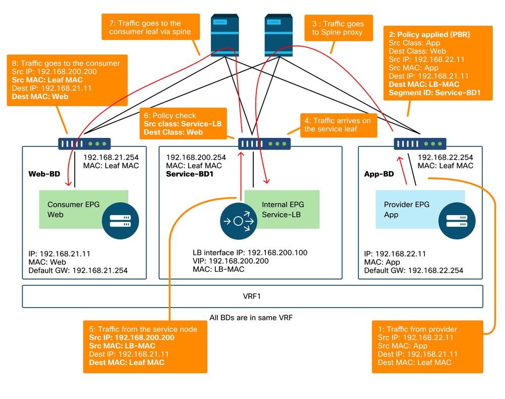
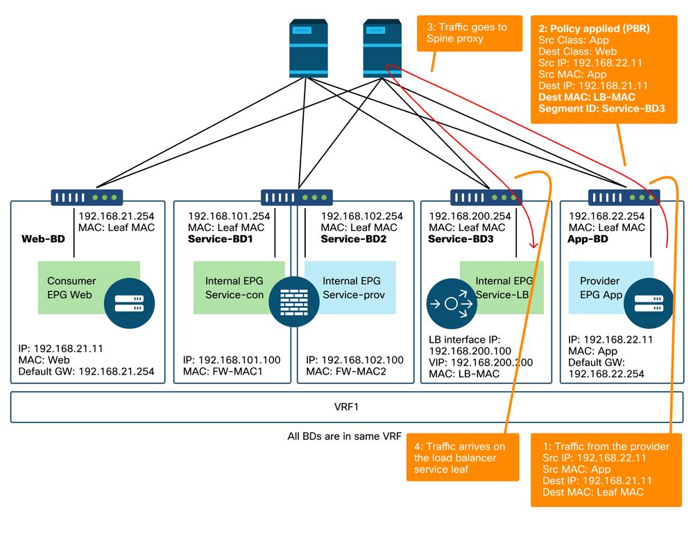
The figure below illustrates the return traffic flow from provider EPG App to consumer EPG Web. Because the return traffic is destined to the original source IP, PBR is required to make the return traffic to go back to the load balancer. Otherwise the consumer endpoint receives the traffic where the source IP is the provider endpoint instead of the VIP. Such traffic will be dropped because the consumer endpoint didn’t initiate traffic to the provider endpoint even if the intermediate network such as the ACI fabric forwards the packet back to the consumer endpoint.
After the traffic from the provider endpoint to the consumer endpoint is redirected to the load balancer, the load balancer changes the source IP to the VIP. Then, the traffic comes back from the load balancer and the traffic goes back to the consumer endpoint.
Load balancer without SNAT forwarding path example - provider to consumer with PBR
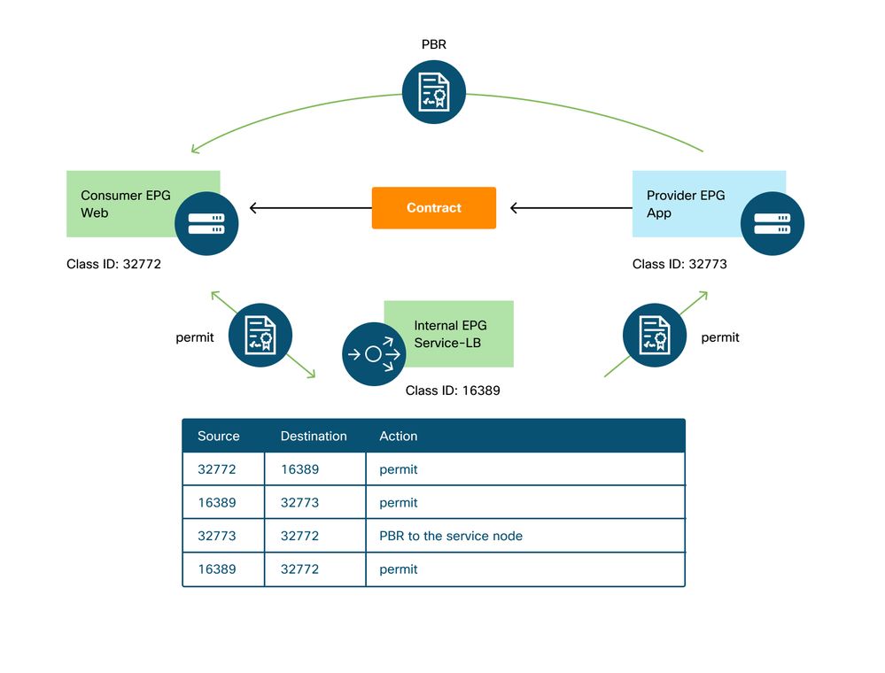
The policies programmed on the leaf nodes.
The figure below and the 'show zoning-rule' output below describe the zoning-rules after Service Graph deployment. In this example, the traffic from pcTag 32772 (Web) to pcTag 16389 (Service-LB) is permitted, the traffic from pcTag 16389 (Service-LB) to pcTag 32773 (App) is permitted, and the traffic from pcTag 32773 (App) to pcTag 32772 (Web) is redirected to 'destgrp-31' (load balancer).
Zoning-rules after Service Graph deployment - load balancer without SNAT
Pod1-Leaf1# show zoning-rule scope 2752513
+---------+--------+--------+----------+----------------+---------+---------+------+-------------------+----------------------+
| Rule ID | SrcEPG | DstEPG | FilterID |      Dir       |  operSt |  Scope  | Name |       Action      |       Priority       |
+---------+--------+--------+----------+----------------+---------+---------+------+-------------------+----------------------+
|   4248  | 16389  | 32773  | default  |    uni-dir     | enabled | 2752513 |      |       permit      |    src_dst_any(9)    |
|   4143  | 32773  | 32772  |    9     |    uni-dir     | enabled | 2752513 |      | redir(destgrp-31) |    fully_qual(7)     |
|   4234  | 16389  | 32772  |    9     | uni-dir-ignore | enabled | 2752513 |      |       permit      |    fully_qual(7)     |
|   4133  | 32772  | 16389  |    8     |     bi-dir     | enabled | 2752513 |      |       permit      |    fully_qual(7)     |
...
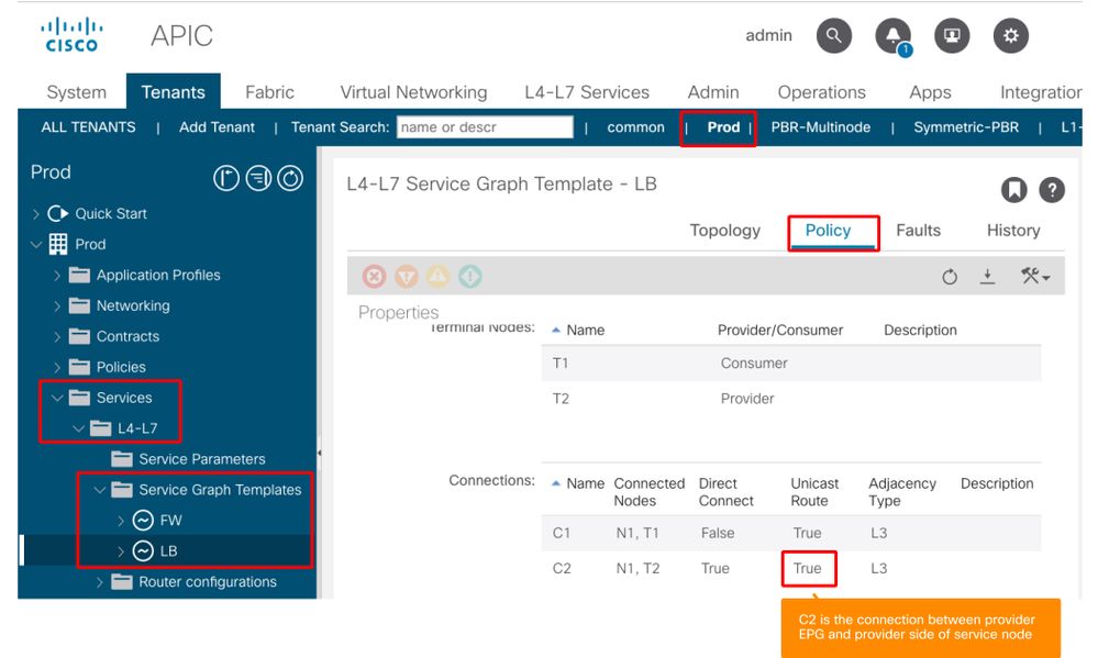
By default, a permit rule for provider EPG (pcTag 32773) to Service-LB (pcTag 16389) is not programmed. To permit bi-directional communication between them for health-checks from the load balancer to provider endpoints, the Direct Connect option on the connection must be set to True. The location is 'Tenant > L4-L7 > Service Graph Templates > Policy'. The default value is False.
Set Direct Connect option
It adds a permit rule for provider EPG(32773) to Service-LB(16389) as below.
Pod1-Leaf1# show zoning-rule scope 2752513
+---------+--------+--------+----------+----------------+---------+---------+------+-------------------+----------------------+
| Rule ID | SrcEPG | DstEPG | FilterID |      Dir       |  operSt |  Scope  | Name |       Action      |       Priority       |
+---------+--------+--------+----------+----------------+---------+---------+------+-------------------+----------------------+
|   4248  | 16389  | 32773  | default  |     bi-dir     | enabled | 2752513 |      |       permit      |    src_dst_any(9)    |
|   4143  | 32773  | 32772  |    9     |    uni-dir     | enabled | 2752513 |      | redir(destgrp-31) |    fully_qual(7)     |
|   4234  | 16389  | 32772  |    9     | uni-dir-ignore | enabled | 2752513 |      |       permit      |    fully_qual(7)     |
|   4133  | 32772  | 16389  |    8     |     bi-dir     | enabled | 2752513 |      |       permit      |    fully_qual(7)     |
|   4214  | 32773  | 16389  | default  | uni-dir-ignore | enabled | 2752513 |      |       permit      |    src_dst_any(9)    |
+---------+--------+--------+----------+----------------+---------+---------+------+-------------------+----------------------+
2. Traffic flow example - Firewall and load balancer without SNAT
PBR can be deployed with multiple service functions in a Service Graph such as firewall as first node and load balancer as second node.
Traffic path example
The figure below illustrates an example of an incoming traffic flow from consumer EPG Web to provider EPG App with two connections: One is from an endpoint in the consumer EPG Web to the load balancer VIP via firewall and the other is from the load balancer to an endpoint in the provider EPG App. The incoming traffic destined to the VIP is redirected to the firewall and then goes to the load balancer without PBR. The load balancer changes the destination IP to one of the endpoints in App EPG associated to the VIP but doesn't translate the source IP. Then, traffic goes to the provider endpoint.
Firewall and load balancer without SNAT forwarding path example - consumer to VIP and load balancer to provider
Firewall and load balancer without SNAT forwarding path example - consumer to VIP and load balancer to provider (continued)
The figure below illustrates the return traffic flow from provider EPG App to consumer EPG Web. Because the return traffic is destined to original source IP, PBR is required to make the return traffic go back to the load balancer.
After the traffic from the provider endpoint to the consumer endpoint is redirected to the load balancer, the load balancer changes the source IP to the VIP. The traffic comes back from the load balancer and is redirected to the firewall. Then, the traffic comes back from the firewall and goes back to the consumer endpoint.
Firewall and load balancer without SNAT forwarding path example - provider to consumer
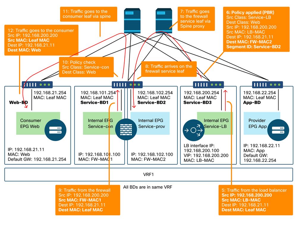
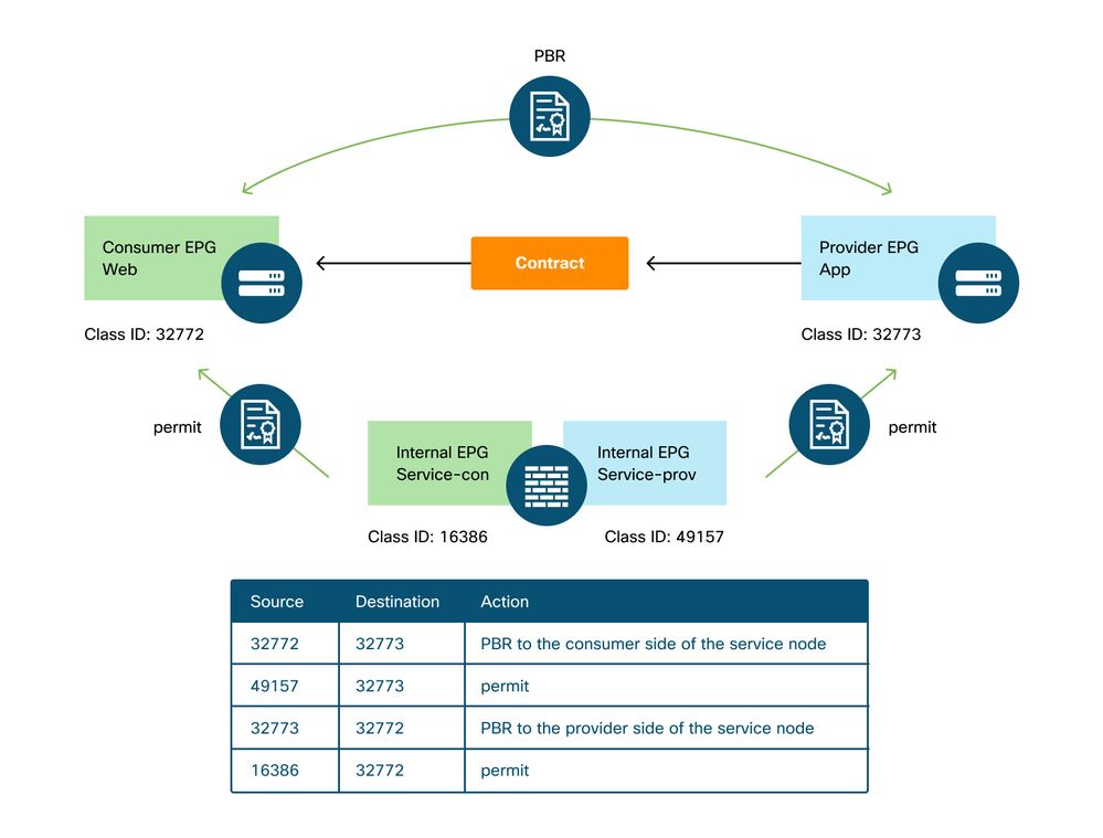
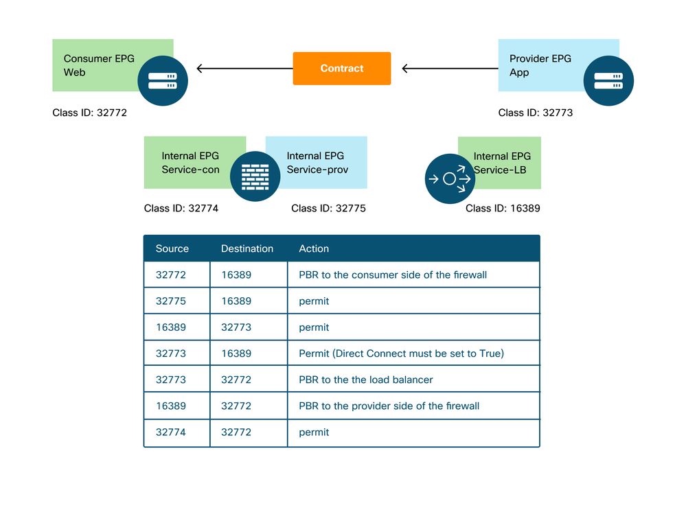
The policies programmed on the leaf nodes
The figure below and the 'show zoning-rule' output shown below describe the zoning-rules after Service Graph deployment. In this example, the traffic from pcTag 32772 (Web) to pcTag 16389 (Service-LB) is redirected to 'destgrp-32' (consumer side of the firewall), the traffic from pcTag 32773 (App) to pcTag 32772 (Web) is redirected to 'destgrp-33' (load balancer), and the traffic from pcTag 16389 (Service-LB) to pcTag 32772 (Web) is redirected to 'destgrp-34' (provider side of the firewall).
Zoning-rules after Service Graph deployment - firewall and load balancer without SNAT
Pod1-Leaf1# show zoning-rule scope 2752513
+---------+--------+--------+----------+----------------+---------+---------+------+-------------------+----------------------+
| Rule ID | SrcEPG | DstEPG | FilterID |      Dir       |  operSt |  Scope  | Name |       Action      |       Priority       |
+---------+--------+--------+----------+----------------+---------+---------+------+-------------------+----------------------+
|   4236  | 32772  | 16389  |    8     |     bi-dir     | enabled | 2752513 |      | redir(destgrp-32) |    fully_qual(7)     |
|   4143  | 32773  | 32772  |    9     |    uni-dir     | enabled | 2752513 |      | redir(destgrp-33) |    fully_qual(7)     |
|   4171  | 16389  | 32773  | default  |     bi-dir     | enabled | 2752513 |      |       permit      |    src_dst_any(9)    |
|   4248  | 16389  | 32772  |    9     | uni-dir-ignore | enabled | 2752513 |      | redir(destgrp-34) |    fully_qual(7)     |
|   4214  | 32774  | 32772  |    9     |    uni-dir     | enabled | 2752513 |      |       permit      |    fully_qual(7)     |
|   4244  | 32775  | 16389  | default  |    uni-dir     | enabled | 2752513 |      |       permit      |    src_dst_any(9)    |
|   4153  | 32773  | 16389  | default  | uni-dir-ignore | enabled | 2752513 |      |       permit      |    src_dst_any(9)    |
+---------+--------+--------+----------+----------------+---------+---------+------+-------------------+----------------------+
In the example above, the Direct Connect option is set to 'True' on the connection between the provider side of the load balancer and the provider EPG. It must be enabled for health-check from the load balancer to provider endpoints. The location is 'Tenant > L4-L7 > Service Graph Templates >Policy'. Please refer to figure 'Set Direct Connect option'.
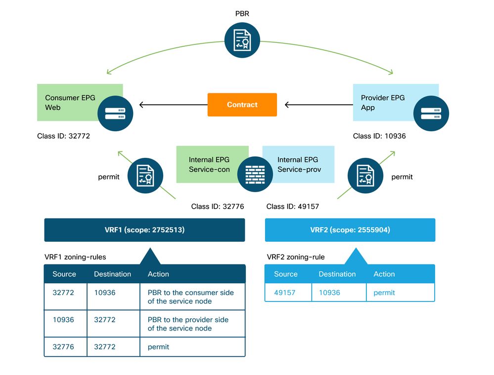
3. Shared service (Inter-VRF contract)
PBR can be enabled in inter-VRF contract. This section explains how the zoning-rules are programmed in the case of EPG to EPG inter-VRF contract.
The policies programmed on the leaf nodes
In case of EPG to EPG inter-VRF contract, policy is always enforced in consumer VRF. Thus, redirection happens on the consumer VRF. For other combinations, please refer to table "Where is policy enforced?" in section "Forwarding".
The figure below and the 'show zoning-rule' output below describes the zoning-rules after Service Graph deployment. In this example, the traffic from pcTag 32772 (Web) to pcTag 10936 (App) is redirected to 'destgrp-36' (consumer side of the service node) and the traffic from pcTag 10936 (App) to pcTag 32772 (Web) is redirected to 'destgrp-35' (provider side of the service node). Both are enforced in VRF1 that is consumer VRF. The traffic from pcTag 32776 (consumer side of the firewall) to pcTag 32772 (Web) is permitted in VRF1.
Zoning-rules after Service Graph deployment - inter-VRF contract
Pod1-Leaf1# show zoning-rule scope 2752513
+---------+--------+--------+----------+----------------+---------+---------+------+-------------------+------------------------+
| Rule ID | SrcEPG | DstEPG | FilterID |      Dir       |  operSt |  Scope  | Name |       Action      |        Priority        |
+---------+--------+--------+----------+----------------+---------+---------+------+-------------------+------------------------+
|   4191  | 32776  | 32772  |    9     |    uni-dir     | enabled | 2752513 |      |       permit      |     fully_qual(7)      |
|   4143  | 10936  | 32772  |    9     | uni-dir-ignore | enabled | 2752513 |      | redir(destgrp-35) |     fully_qual(7)      |
|   4136  | 32772  | 10936  |    8     |     bi-dir     | enabled | 2752513 |      | redir(destgrp-36) |     fully_qual(7)      |
+---------+--------+--------+----------+----------------+---------+---------+------+-------------------+------------------------+
The traffic from pcTag 49157 (provider side of the firewall) to pcTag 10936 (App) is permitted in VRF2 because both are in VRF2.
Pod1-Leaf1# show zoning-rule scope 2555904
+---------+--------+--------+----------+---------+---------+---------+------+----------+----------------------+
| Rule ID | SrcEPG | DstEPG | FilterID |   Dir   |  operSt |  Scope  | Name |  Action  |       Priority       |
+---------+--------+--------+----------+---------+---------+---------+------+----------+----------------------+
|   4249  | 49157  | 10936  | default  | uni-dir | enabled | 2555904 |      |  permit  |    src_dst_any(9)    |
+---------+--------+--------+----------+---------+---------+---------+------+----------+----------------------+
Revision History
| Revision | Publish Date | Comments |
|---|---|---|
1.0 |
10-Aug-2022
|
Initial Release |
Contributed by Cisco Engineers
- ACI Escalation Engineers
- Technical Marketing
 Feedback
Contact Cisco
- Open a Support Case

- (Requires a Cisco Service Contract)