Cisco ACI and Cisco Secure ADC Design Guide
Available Languages
Bias-Free Language
The documentation set for this product strives to use bias-free language. For the purposes of this documentation set, bias-free is defined as language that does not imply discrimination based on age, disability, gender, racial identity, ethnic identity, sexual orientation, socioeconomic status, and intersectionality. Exceptions may be present in the documentation due to language that is hardcoded in the user interfaces of the product software, language used based on RFP documentation, or language that is used by a referenced third-party product. Learn more about how Cisco is using Inclusive Language.
- US/Canada 800-553-2447
- Worldwide Support Phone Numbers
- All Tools
 Feedback
 Feedback
This document describes Cisco® Application Centric Infrastructure (Cisco ACI®) and interoperability with Cisco Secure ADC.
The document discusses design considerations and deployment options for Cisco ACI with Cisco Secure ADC, an advanced application delivery controller (ADC), from three aspects: network design, ADC design, and multitenant design. This document covers features up to Cisco ACI Release 5.1.
One of the key considerations of the network design with an ADC is to ensure incoming and return traffic go through the same device. There are various options you can use to insert the application delivery controller in the data center. One way is to use the load balancer as the gateway for servers. Another option is to use Source Network Address Translation (SNAT) on the ADC to ensure traffic is returned back to it. In an ACI infrastructure, Policy-Based Redirect (PBR) can also be used to make the return traffic go back to the load balancer.
The advantage of leveraging the ACI PBR functionality is that it makes the overall configuration simpler and allows for easy changes to the environment. For example, if an organization wanted to add an additional security device such as a Web Application Firewall in the path to inspect the traffic, this could be done with ACI PBR functionality without requiring any changes to the rest of the environment.
Cisco Secure ADC can be deployed in different high-availability modes. This document will cover the two common Cisco Secure ADC deployment modes: active-active and active-standby. Various design considerations, such as endpoint movement during failovers, virtual MAC, source MAC-based forwarding, Link Layer Discovery Protocol (LLDP), and IP aging will be discussed around each of the deployment modes.
Multitenancy is supported by both Cisco ACI and Cisco Secure ADC in different ways. This document will cover a few ways that multitenancy constructs on ACI can be mapped to multitenancy on Secure ADC. The discussion will revolve around tenants, Virtual Routing and Forwarding (VRF), virtual ADCs, and also multitenancy, based on which Secure ADC form factor you use.
The Cisco Application Policy Infrastructure Controller (APIC) is used to manage the ACI fabric. The Cisco ACI ServiceCenter is an application that runs on the APIC controller that augments the integration between ACI and Cisco Secure ADC.
To best understand the network design presented in this document, you should have basic knowledge about Cisco ACI and the Cisco Secure ADC.
Cisco ACI offers the capability to insert Layer 4–7 services, such as firewalls, load balancers, and Intrusion Prevention Systems (IPSs), using a feature called a service graph. For more information, refer to the Cisco ACI ervice graph design white paper at www.cisco.com/c/en/us/solutions/collateral/data-center-virtualization/application-centric-infrastructure/white-paper-c11-734298.html
The service graph functionality can then be enhanced by associating to Policy-Based Redirect (PBR) policies. For more detailed information on PBR, refer to the Cisco ACI PBR white paper: www.cisco.com/c/en/us/solutions/data-center-virtualization/application-centric-infrastructure/white-paper-c11-739971.html
Cisco's Secure ADC product family is comprised of hardware, modularized software, and virtual appliances.
For more information on load balancing basics, refer to www.radware.com/glossary/loadbalancing/.
For other load balancing concepts, such as virtual load balancing and cloud load balancing, see www.radware.com/products/load-balancing-application-delivery/.
This document uses the following terms with which you must be familiar:
● Application Delivery Controller (ADC)
● Bridge Domain (BD)
● Default Gateway (DG)
● Endpoint Group (EPG)
● Layer 3 Out or external routed network (L3Out)
● Subnet-based EPG in Layer 3 Out (L3Out EPG)
● Virtual Routing and Forwarding (VRF)
● Virtual MAC (VMAC)
● Service graph
● Direct Server Return (DSR)
● Policy-Based Redirect (PBR)
● Load Balancer (LB)
● Route Health Injection (RHI)
● Source Network Address Translation (SNAT)
● ADC-IP (IP address on a Cisco Secure ADC interface associated with a VLAN)
● Floating ADC-IP (IP address that two Secure ADC share)
This document will use the term load balancer (LB) and application delivery controller (ADC) interchangeably as an ADC is an LB with advanced application features and functionality.
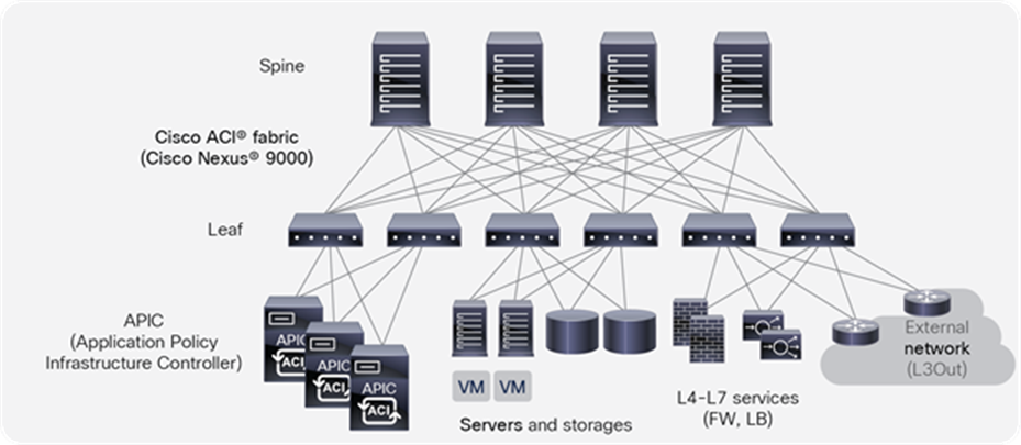
Cisco Application Centric Infrastructure (Cisco ACI) technology enables you to integrate virtual and physical workloads in a programmable, multihypervisor fabric to build a multiservice or cloud data center. The Cisco ACI fabric consists of discrete components that operate as routers and switches, but it is provisioned and monitored as a single entity.
Cisco ACI physical topology
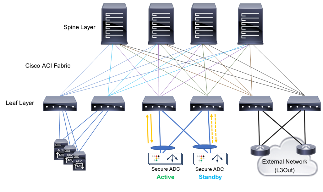
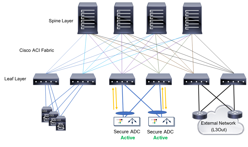
The physical Cisco ACI fabric is built on a Cisco Nexus® 9000 Series spine-leaf design; its topology is illustrated in Figure 1, using a bipartite graph, where each leaf is a switch that connects to each spine switch, and no direct connections are allowed between leaf nodes and between spine nodes. The leaf nodes act as the connection point for all servers, storage, physical or virtual L4-L7 service devices, and external networks, and the spine acts as the high-speed forwarding engine between leaf nodes. Cisco ACI fabric is managed, monitored, and administered by the Cisco APIC.
Cisco Nexus 9000 Series switches that support ACI spine or leaf mode can be found at www.cisco.com/c/en/us/products/switches/nexus-9000-series-switches/index.html
The minimum ACI fabric design should have two spine nodes, two leaf nodes, and three APICs. (Figure 1 illustrates four spine nodes and six leaf nodes.) The fabric design can scale up to 500 leaf nodes per ACI fabric. See the latest ACI-verified scalability guide for details: www.cisco.com/c/en/us/support/cloud-systems-management/application-policy-infrastructure-controller-apic/tsd-products-support-series-home.html.
Although Figure 1 shows a separate leaf node pair for APIC cluster, servers, storage, and others, it’s not mandatory to use a separate leaf node. Even though there is no specific role configuration on each leaf, a leaf connected to the external network is called a border leaf.
Cisco ACI logical constructs
Instead of configuring individual switches in a fabric, the logical network and security are provisioned and monitored as a single entity in the ACI fabric.
The fundamental security architecture of the ACI solution follows a permit list model. A contract is a policy construct used to define communication between Endpoint Groups (EPGs). Without a contract between EPGs, no unicast communication is possible between those EPGs by default. A contract is not required to allow communication between endpoints in the same EPG.
Figure 2 shows the relationship between EPGs and contracts.
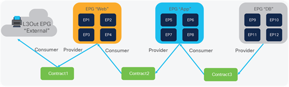
An EPG provides or consumes a contract (or provides and consumes a contract). For instance, the app EPG in the example in Figure 2 provides a contract that the Web EPG consumes and consumes a contract that the DB EPG provides.
An endpoint can belong to one EPG. Physical, virtual, and container endpoints can co-exist in the same EPG. How to define which EPG an endpoint belongs to is based on the following EPG types:
● L3Out EPG - based on the IP subnet (longest prefix match)
● EPG - based on the leaf interface and virtual LAN (VLAN) ID, or leaf interface and virtual extensible LAN (VXLAN)
● uSeg EPG (also called micro-EPG) - based on IP, MAC VM attributes such as VM name, or a combination of IP, MAC, and those attributes
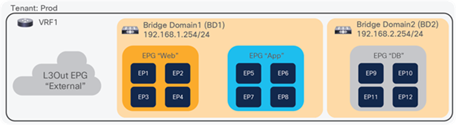
Figure 3 illustrates ACI logical network design constructs. The tenant is a logical entity to construct EPGs, contracts, and network components for EPGs. Each EPG belongs to a Bridge Domain (BD) that is a broadcast domain boundary in ACI. A BD belongs to a VRF.
In this example, web and app EPGs are in the same BD, BD1, and DB EPG is in a dedicated BD, BD2. Unlike traditional networks, multiple different EPGs can be in the same subnet as different security groups and zones.
Cisco ACI Service Graph and PBR
The Layer 4–7 Service Graph is a feature in Cisco ACI to insert Layer 4–7 service devices such as a firewall, load balancer, and IPS between the consumer and provider EPGs. Service Graph itself is not mandatory to design Layer 4–7 service devices in ACI, as long as the Layer 4–7 devices are inserted in the network using the general routing and bridging.
Figure 4 provides an example using routing and bridging to insert a load balancer without Service Graph. For incoming traffic from an endpoint in the consumer EPG, the VIP is routed by the ACI fabric. Why? Because the VIP is an ACI internal endpoint if the gateway of the server is the load balancer; the return traffic from an endpoint in the provider EPG is simply bridged by the ACI fabric.
If the load balancer interface and the servers are not in the same subnet, the use of SNAT on the load balancer can make the return traffic back to the load balancer. Even if the use of Service Graph is not mandatory in this case, the use of Service Graph offers these advantages:
● ACI automatically manages VLAN deployment on the ACI fabric and the virtual networks for service node connectivity.
● ACI automatically connects and disconnects virtual Network Interface Cards (vNICs) for virtual service appliances using Virtual Machine Manager (VMM). To see more on ACI VMM, please visit the following link: www.cisco.com/c/en/us/solutions/collateral/data-center-virtualization/application-centric-infrastructure/white-paper-c11-731961.html.
● ACI provides a more logical view of service insertion between consumer and provider EPGs.
● ACI can redirect traffic to the service node without the need for the service node to be the default gateway of the servers.as
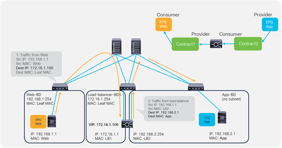
One of the main advantages of Service Graph is the PBR feature, which is helpful to insert Layer 4–7 service devices. With this PBR feature, ACI redirects traffic matched with the contract without relying on routing or bridging. For load balancer designs, PBR can be used for return traffic generated from the servers to make the return traffic go back to a load balancer that doesn’t perform SNAT.
Figure 5 illustrates this with an example. The incoming traffic from an endpoint in a consumer EPG to VIP doesn’t require PBR because it’s routed to the VIP that is also an ACI internal endpoint. For the return traffic from an endpoint in the provider EPG, PBR is required if the load balancer didn’t perform SNAT on the incoming traffic. Without PBR, traffic would directly go back to the consumer endpoint, which prevents the load balancer from seeing both directions of the traffic.
Note: Service Graph is mandatory in order to use PBR.
For more detailed information on Service Graph design and PBR, refer to the following white papers:
● Service Graph Design with Cisco Application Centric Infrastructure White Paper: www.cisco.com/c/en/us/solutions/collateral/data-center-virtualization/application-centric-infrastructure/white-paper-c11-734298.html
● Cisco Application Centric Infrastructure Policy-Based Redirect Service Graph Design White Paper: www.cisco.com/c/en/us/solutions/data-center-virtualization/application-centric-infrastructure/white-paper-c11-739971.html
Cisco Secure ADC is a family of products available in both software and hardware designed around predictable application performance with built-in attack mitigation architecture. On top of all the other Layer 4-7 application delivery functions, performance optimization, and security functions, the Secure ADC products also deliver enhanced traffic encryption processing performance. It also provides application performance monitoring and advanced denial-of-service protection, as well as a Web Application Firewall.
Some of the additional use cases for deploying an Secure ADC beyond the L4-L7 load balancing are:
● SSL Offloading
● SSL Interception both inbound or outbound
● Traffic Steering
● Web Application Firewall
● Application Rewrite
● Application Caching
● Application Protection
● Application Monitoring
● Application Authentication
● Global Load Balancing
These topics are out of the scope of this document but are listed here for the reader to understand the additional value that Cisco Secure ADC provides.
For more information refer to www.cisco.com/c/en/us/products/collateral/security/secure-adc-alteon-ds.html
Secure ADC appliances
The Cisco Secure ADC comes in a wide range of physical appliances that can support up to 320 Gbps on a single device at the time of the writing of this document.
The Cisco Secure ADC is also available as a virtual appliance that can be deployed in both private and public clouds.
For more information refer to www.cisco.com/c/en/us/products/collateral/security/alteon-technical-specs-ds.html
Overview
When inserting a load balancer into a Cisco ACI fabric, it is important to understand the desired traffic flow. There are two main types of traffic patterns to consider:
1. Incoming and return traffic go through the same load balancer that is a stateful device.
2. The traffic to the other VIP goes via a load balancer, and the return traffic from servers goes directly back to the client: this is called Direct Server Return (DSR).
The following is a list of questions that helps to understand the requirement.
● Is the load balancer deployed in Layer 2 or Layer 3 mode? (Cisco Secure ADC supports both Layer 2 and Layer 3.)
● How is the return traffic handled? Is the load balancer the gateway? Is the load balancer doing SNAT? Is ACI PBR redirecting the traffic to the load balancer, or is the load balancer deployed in DSR mode?
● What high-availability (HA) option is used for the load balancer - active/standby HA pair, active/active HA pair, or multiple HA pairs?
● Is the VIP in the same subnet range as the IP address of a load balancer interface (Cisco Secure ADC calls it “ADC-IP”) or outside of the subnet range?
● What are the dynamic routing protocol requirements?
● In this document, the assumption is that the load balancer is deployed in Layer 3 mode with active/standby HA because this represents the majority of the deployments.
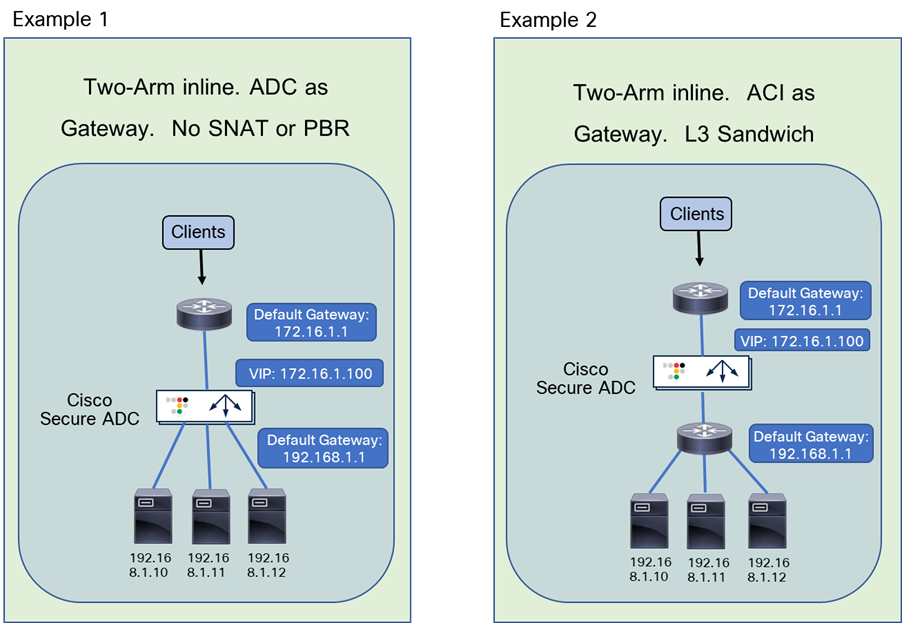
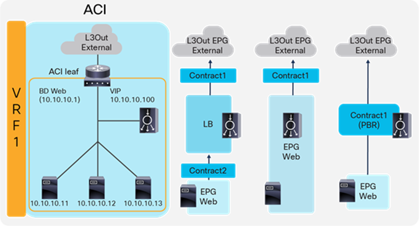
Figure 6 illustrates common load balancer network design options.
● In the first example on the left side of the image, the load balancer is deployed in two-arm mode, and it is the default gateway of the servers. SNAT or PBR is not required because the load balancer is in the traffic path based on routing.
● In the second example, the load balancer is deployed in two-arm mode, and it is placed between two different routers or VRFs: one is for external connectivity and the other is the gateway of servers. SNAT or PBR is not required because the load balancer is in the traffic path based on routing.
● In the third example, the load balancer is deployed in two-arm mode in a way that not all traffic from the servers has to go via the load balancer itself. SNAT or PBR is required to return traffic back to the load balancer. If neither SNAT nor PBR is used, the return traffic would go back to the client directly, and as a result, the traffic would be dropped by the client. The reason: because the source IP address of the return traffic (of the server) is different from the destination IP address of the incoming traffic sent by the client, which was directed to the VIP.
● In the fourth example, the load balancer is deployed in one-arm mode in a way that not all traffic from the servers has to go via the load balancer itself. SNAT or PBR is required to return traffic back to the load balancer. If neither SNAT nor PBR is used, the return traffic goes back to the client directly, which will be dropped by the client because the source IP address of the return traffic is different from the destination IP address of the incoming traffic sent by the client. The load balancer interface can be in the same or a different subnet with servers. This design can be used for Layer 2 DSR, where the return traffic doesn’t go back via the load balancer. For Layer 2 DSR, the load balancer and servers must be in the same subnet.
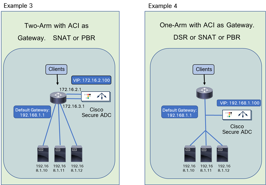
Load balancer designs are often categorized using the terminology “two-arm” and “one-arm.” From the load balancer’s perspective, the number of arms is nothing more than the number of interfaces or VLAN interfaces that are created on the load balancer. There should be no significant difference between the two modes from a load balancer performance perspective. In the case of a two-arm design, traffic from the client arrives on an interface on the load balancer and is forwarded to a server through the other interface. In the case of a one-arm design, traffic arrives and leaves using the same interface on the load balancer.
The following subsections explain how to translate the typical load balancer design options just described into ACI network constructs. Table 1 summarizes the comparison of the design options in a Cisco ACI fabric.
In these examples, the load balancer external interface IP and the VIP are in the same subnet. For the case in which they are not in the same subnet, refer to the VIP outside of the self IP subnet range section. Even if the examples reference north-south traffic flows, which is traffic from the outside to internal servers through a VIP, the same design considerations can also be applied to east-west traffic flows, which is traffic from internal servers to other internal severs through a VIP.
Table 1. Typical load balancer design options in Cisco ACI fabric
|
|
How to make the return traffic go back via the Load Balancer (LB) |
Design |
Benefit |
Consideration |
| LB is the gateway for the servers |
Use LB as the gateway for the servers associated to the VIP |
Simple network design |
Intersubnet traffic must go through the load balancer |
|
| LB as routing next hop (VRF sandwich) |
Use the ACI fabric as a gateway for the servers associated to the VIP; LB is routing next hop of the ACI fabric |
Take advantage of the ACI anycast gateway |
Need to manage two VRFs |
|
| SNAT or PBR |
Use the ACI fabric as a gateway for the LB and also for the servers associated to the VIP; use SNAT or PBR to return traffic via the LB |
Take advantage of the ACI anycast gateway Selective traffic redirection by using PBR |
Service Graph is mandatory to use PBR |
|
| SNAT or PBR |
Use the ACI fabric as a gateway for the LB and also for the servers associated to the VIP; use SNAT or PBR to return traffic back to load balancer |
Take advantage of the ACI anycast gateway Selective traffic redirection by using PBR |
Service Graph is mandatory to use PBR |
Two-arm (inline) load balancer as gateway
The first example is one where the two-arm inline load balancer is the default gateway of the servers. SNAT or PBR is not required because the load balancer is in the traffic path based on routing. In this case, two VLAN segments are required. Thus, in case of ACI, you need to use two bridge domains: one is for the load balancer external interface and the other is for the load balancer internal interface. Figure 7 provides an example of this scenario. In this example, the load balancer VIP and the load balancer external interface IP are in the same subnet.
“LB-Ext” bridge domain for the load balancer external interface has the bridge domain subnet that is the gateway for the load balancer to the external network through L3Out. The “Web” bridge domain for the load balancer internal interface and the servers doesn’t have a bridge domain subnet because the load balancer internal IP address is the gateway for the servers. The L3Out connected to the external network has the L3Out EPG “External” with the external network subnets that are allowed to access the load balancer VIP in the “LB-Ext” bridge domain.
The traffic coming from the external network arrives to the ACI fabric and it is routed to the VIP (192.168.10.100) because the VIP is an ACI local endpoint in the “LB-Ext” bridge domain. The traffic is then load balanced to one of the servers associated to the VIP. The return traffic from the server arrives on the load balancer internal interface because it is the gateway of the servers. The load balancer then routes the traffic back to the ACI fabric that is the gateway of the load balancer to the external network.
Figure 8 illustrates the contract configuration for this design. To permit end-to-end traffic, one of the following configurations is required:
● Two contracts – One is between the L3Out EPG “External” for the external network and the EPG “LB-Ext” for the load balancer external interface, and the other is between the EPG “LB-In” for the load balancer internal interface and “Web” EPG for the servers. All EPGs are created by a user.
● One contract – If there is no security requirement, the load balancer internal interface and the servers can be combined into one EPG instead of different EPGs with a contract. All EPGs are created by a user.
● Service Graph – Use Service Graph on a contract between the L3Out EPG “External” for the external network and “Web” EPG. The EPGs (called “internal service EPGs” or “shadow EPGs”) for the load balancer external and internal interfaces are automatically created through Service Graph rendering. The internal service EPGs are not displayed in the GUI, and the user doesn’t need to manage them.
Highlights of key characteristics of this design:
● The load balancer internal interface and the EPG for the servers are in the same bridge domain (ACI is used for bridging)
● ACI can be used as the next hop for the external side of the load balancer
● All intersubnet traffic goes through the load balancer
● SNAT or PBR is not required
● Service Graph is not mandatory
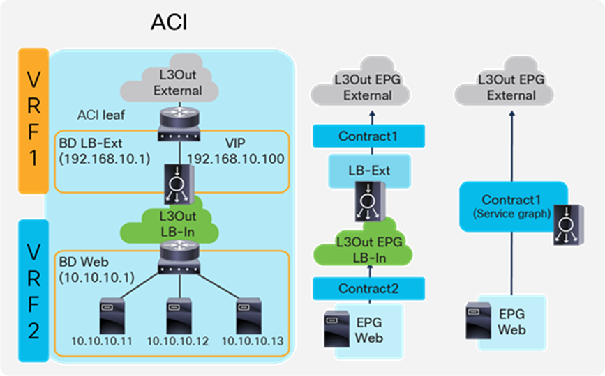
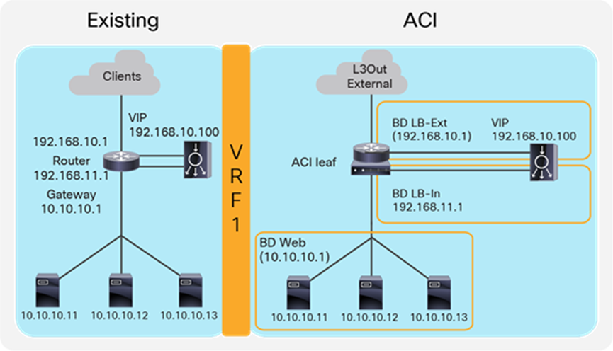
Two-arm (inline) load balancer with fabric as gateway
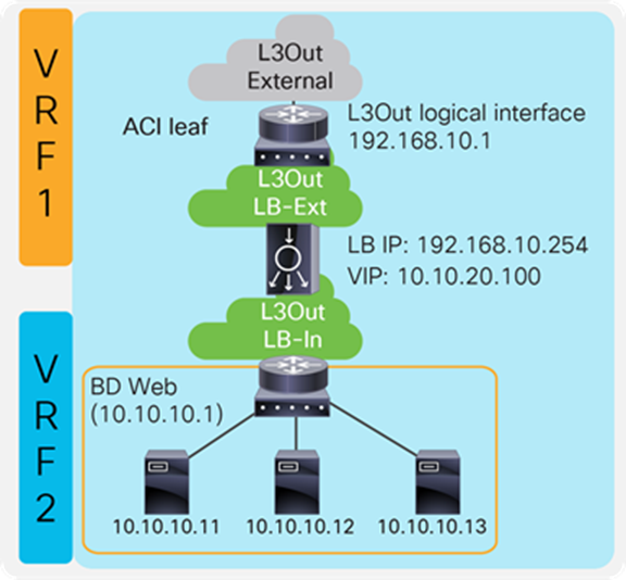
This design consists of a two-arm inline load balancer placed between two routing instances, such as two separate routers or two VRFs. The internal-facing routing instance provides the gateway to the servers. SNAT or PBR is not required because the load balancer is in the traffic path based on routing. In the case of ACI, you can use two VRFs (instead of using an external router): one is for the load balancer external interface and the other is for the load balancer internal interface. The two VRFs configured in ACI are not for the purpose of multitenancy, but simply to route traffic via the load balancer. No inter-VRF, route-leaking configuration is required on the ACI fabric itself because the load balancer is in between VRFs.
Figure 9 provides an example of this configuration. In this example, the load balancer VIP and the load balancer external interface IP are in the same subnet.
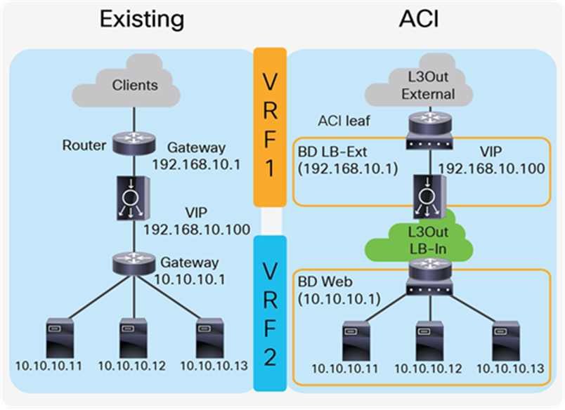
The external-facing VRF, “VRF1,” has the L3Out connected to the external network and the L3 bridge domain, “LB-Ext,” that has the gateway for the load balancer to the external network. The L3Out connected to the external network has the L3Out EPG “External” with the external network subnets that are allowed to access to the load balancer VIP in the “LB-Ext” bridge domain. The internal-facing VRF, “VRF2,” has the L3 bridge domain, “Web,” that is the gateway for the servers and the L3Out “LB-In” for the load balancer internal interface connectivity. The L3Out “LB-In” has the L3Out EPG “LB-In” with the external network subnets that are allowed to access to the servers through the load balancer.
The traffic coming from the external network arrives on the ACI fabric on VRF1 and it is routed to the VIP (192.168.10.100) because the VIP is an ACI local endpoint in the “LB-Ext” bridge domain. Traffic is then load balanced to one of the servers associated to the VIP. The load balancer must have a route to the server subnet (10.10.10.0/254). This load balancer route uses the ACI IP address on the L3Out logical interface of the L3Out “LB-In” and then traffic arrives on the servers in VRF2. The return traffic from the server arrives on the ACI fabric via the “Web” bridge domain on VRF2 because the “Web” bridge domain subnet is the gateway of the servers. ACI VRF2 must have a route to the external network via the load balancer internal interface. Then, the load balancer routes the traffic back to the ACI leaf that is the gateway of the load balancer to the external network.
If the load balancer does SNAT and uses the load balancer internal IP subnet range as NAT’ed IP, the load balancer internal interface can be in a bridge domain instead of an L3Out because the NAT’ed IP is a local endpoint IP in VRF2 that doesn’t require an additional route.
Figure 10 illustrates the contract configuration for this design. To permit end-to-end traffic, one of the following configurations is required:
● Two contracts – One is between the L3Out EPG “External” for the external network and the EPG “LB-Ext” for the load balancer external interface, and the other is between the L3Out EPG “LB-In” for the load balancer internal interface and “Web” EPG for the servers. All EPGs are created by a user.
● Service Graph – A Service Graph is used on a contract between the L3Out EPG “External” to connect the external network and “Web” EPG. L3Out EPG “LB-In” for the load balancer internal interface needs to be created separately and is selected in the Service Graph. The EPG “LB-Ext,” internal service EPG, for the load balancer external interface is automatically created through Service Graph rendering. The internal service EPG is not displayed in the GUI, and the user doesn’t need to manage it.
Key characteristics of this design:
● This is the traditional VRF sandwich design.
● ACI is used for routing.
● The external interface of the load balancer is connected to a bridge domain via an EPG.
● The internal interface of the load balancer is connected to an L3Out via an L3Out EPG.
● All inter-VRF traffic goes through the load balancer.
● SNAT or PBR is not required.
● Service Graph is not mandatory.
● If SNAT is enabled on the load balancer using the internal interface subnet range as NAT'ed IP, L3Out for the internal interface of the load balancer is not required.
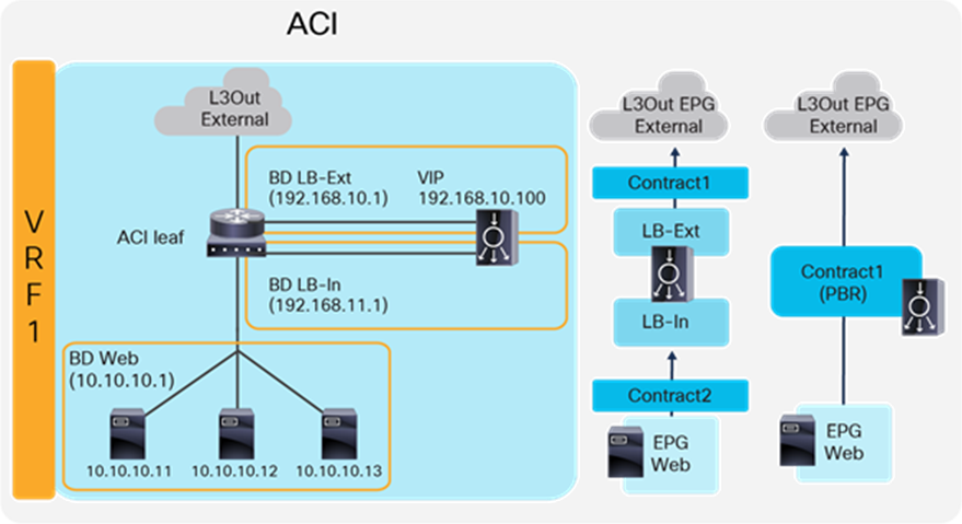
Two-arm load balancer with fabric as the gateway
This design describes the integration with a two-arm load balancer in a way that not all traffic from the servers has to go via the load balancer itself. SNAT or PBR is required to make the return traffic go back to the load balancer. Without the use of SNAT or PBR, the return traffic from the servers would bypass the load balancer and then the client that receives the return traffic doesn’t handle the traffic as the reply because the source IP address of the return traffic is different from the destination IP address of the traffic sent by the client.
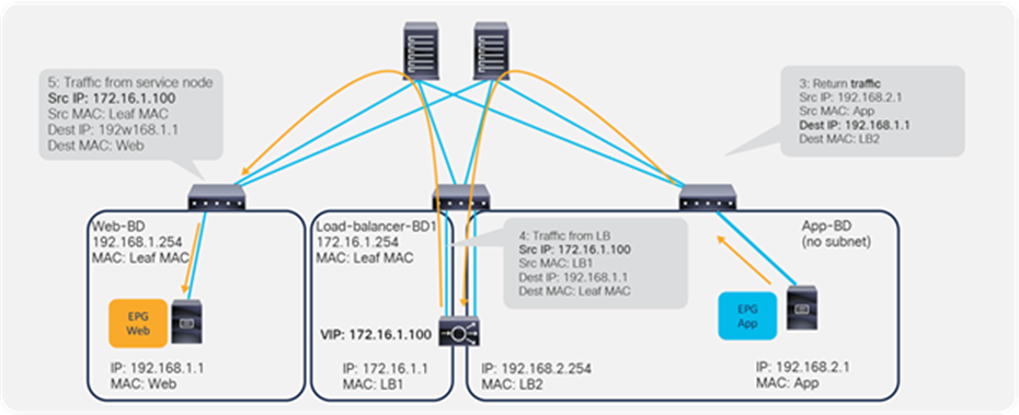
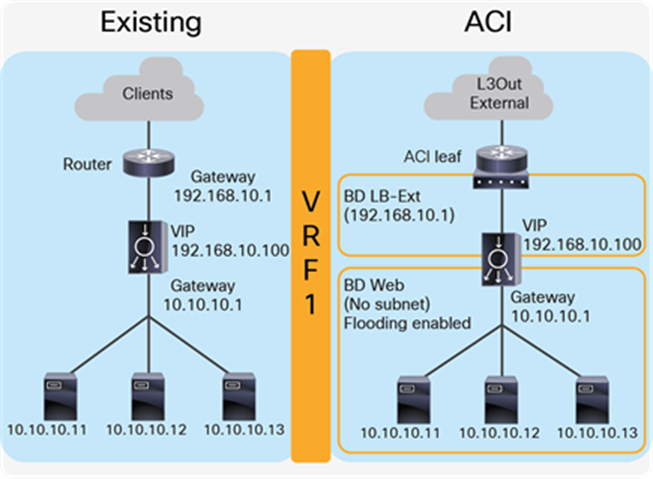
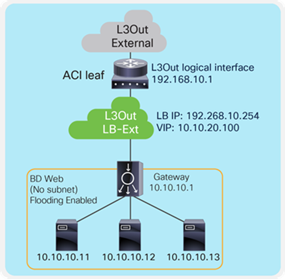
Figure 11 provides an example of this scenario. This example consists of three bridge domains: one is for the external interface of the load balancer, another is for the internal interface of the load balancer, and the third is for the servers. If the servers and the internal interface of the load balancer are in the same subnet, the two bridge domains can be combined into one bridge domain. In this example, the load balancer VIP and the load balancer external interface IP are in the same subnet.
The “LB-Ext” bridge domain for the load balancer external interface has the bridge domain subnet that is the gateway for the load balancer to the external network. The “LB-In” bridge domain for the load balancer internal interface has the bridge domain subnet that is the gateway for the load balancer to the server network. The “Web” bridge domain for the servers has the bridge domain subnet that is the gateway for the servers. The L3Out connected to the external network has the L3Out EPG “External” with the external network subnets that are allowed to access the load balancer VIP in the “LB-Ext” bridge domain.
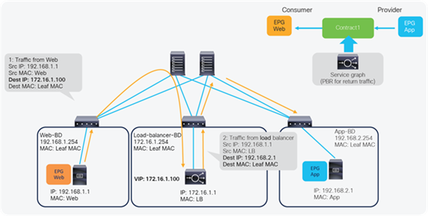
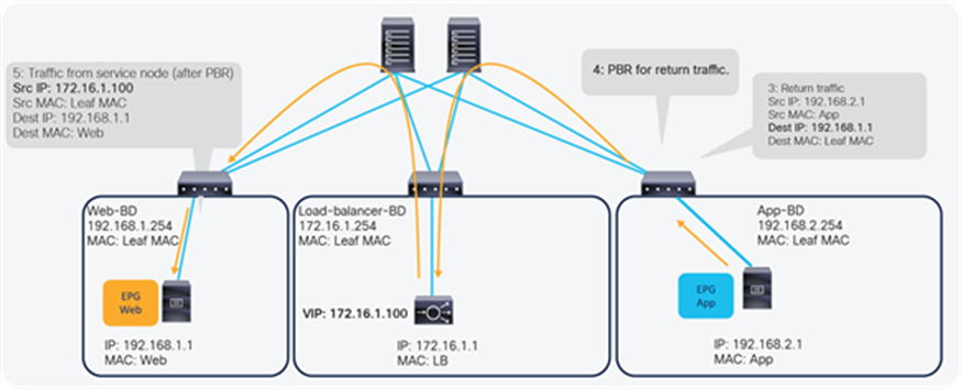
The traffic coming from the external network arrives on the ACI fabric and is routed to the VIP (192.168.10.100) because the VIP is an ACI local endpoint in the “LB-Ext” bridge domain. The traffic is then load balanced to one of the servers associated to the VIP. The load balancer must have the route to the server subnet (10.10.10.0/254) via the “LB-In” bridge domain subnet IP. The return traffic from the server arrives on the “Web” bridge domain subnet IP because it is the gateway for the servers. SNAT or PBR is required to make the return traffic go back to the load balancer. If SNAT was enabled on the load balancer, the destination IP of the return traffic will be at the IP in the “LB-In” bridge domain, which is owned by the load balancer (for example, 192.168.11.10), so that the return traffic is routed and sent to the load balancer internal interface. If PBR is enabled for the return traffic, PBR is applied on the traffic from the “Web” EPG to L3Out EPG “External.” As a result, that traffic is redirected to the load balancer internal interface. The load balancer then routes the return traffic back to the ACI fabric “LB-Ext” bridge domain subnet IP that is the gateway of the load balancer to the external network.
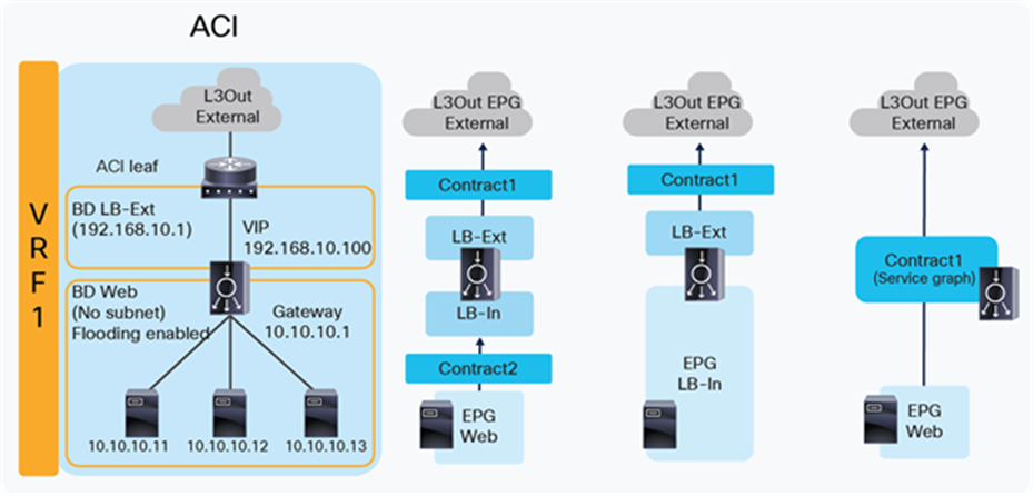
Figure 12 illustrates the contract configuration for this design. To permit end-to-end traffic, one of the following configurations is required:
● Two contracts (SNAT on the load balancer) – One is between the L3Out EPG “External” for the external network and the EPG “LB-Ext” for the load balancer external interface, and the other is between the EPG “LB-In” for the load balancer internal interface and the “Web” EPG.
● Service Graph (PBR for return traffic) – Use Service Graph PBR on a contract between the L3Out EPG “External” for the external network and the “Web” EPG. The EPGs (called “internal service EPGs” or “shadow EPGs”) for the load balancer external and internal interfaces are automatically created through Service Graph rendering. The internal service EPGs are not displayed in the GUI, and the user doesn’t need to manage them.
The following points summarize some key characteristics of this design:
● ACI provides routing for the servers and the load balancer; it is their default gateway or routing next hop.
● PBR or SNAT is required.
● The service device can be in the same bridge domain as the servers or in a different bridge domain.
● If PBR is used to make the return traffic go back to the load balancer, Service Graph is mandatory, and specific traffic is redirected to the load balancer internal interface.
● If SNAT is used to make the return traffic go back to the load balancer, the NAT’ed IP must be in the load balancer internal side subnet range.
One-arm load balancer with fabric as the gateway
This design describes the integration with a one-arm load balancer in a way that not all traffic from the servers has to go via the load balancer itself. SNAT or PBR is required to make the return traffic go back to the load balancer. Without the use of SNAT or PBR, the return traffic from the servers would bypass the load balancer and then the client that receives the return traffic doesn't handle the traffic as the reply because the source IP address of the return traffic is different from the destination IP address of the traffic sent by the client.
Note: This design can also provide Layer 2 DSR, where the return traffic from the servers directly goes back to the client without going through the load balancer. The Layer 2 DSR design requires the load balancer and servers to be in the same subnet and also requires that the VIP is configured as a loopback address on the server and that the server is configured not to answer ARP requests for the VIP. This document mainly explains designs with SNAT or PBR. Refer to ACI Fabric Endpoint Learning White Paper for Layer 2 DSR design considerations in ACI.
Figure 13 provides an example of this scenario. This example consists of one bridge domain for the load balancer interface and the servers. The load balancer VIP and the load balancer external interface IP are in the same bridge domain subnet in this example, but they can be in different bridge domains if needed.
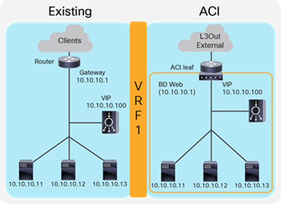
The “Web” bridge domain that is configured with a subnet is the gateway for the load balancer itself and for the servers. The L3Out connected to the external network has the L3Out EPG “External” with the external network subnets that are allowed to access the load balancer VIP in the “Web” bridge domain.
The traffic coming from the external network arrives on the ACI fabric and is routed to the VIP (10.10.10.100) because the VIP is an ACI local endpoint in the “Web” bridge domain. The traffic is then load balanced to one of the servers associated to the VIP. The return traffic from the server arrives on the “Web” bridge domain subnet IP because it is the gateway for the servers. SNAT or PBR is required to make the return traffic back to the load balancer. If SNAT is enabled on the load balancer, the destination IP of the return traffic is the IP in the “Web” bridge domain, which is owned by the load balancer (for example, 10.10.10.10). ACI bridges the traffic from the servers to the load balancer. If PBR is enabled for the return traffic, PBR is applied on the traffic from the “Web” EPG to the L3Out EPG “External.” ACI redirects the traffic to the load balancer internal interface. The load balancer then routes the return traffic back to the subnet IP address of the “Web” bridge domain.
Figure 14 illustrates the contract configuration for this design. To permit end-to-end traffic, one of the following configurations is required:
● Two contracts (SNAT on the load balancer) – One is between the L3Out EPG “External” for the external network and the EPG “LB” for the load balancer interface, and the other is between the EPG “LB” for the load balancer interface and “Web” EPG.
● One contract (SNAT on the load balancer) – If the interface of the load balancer and the servers is in the same bridge domain and there is no security requirement, they can be combined to one EPG instead of different EPGs with a contract.
● Service Graph with PBR for return traffic – This design uses Service Graph PBR on a contract between the L3Out EPG “External” for the external network and the “Web” EPG. The EPG (called “internal service EPG” or “shadow EPG”) for the load balancer interface is automatically created through Service Graph rendering. The internal service EPG is not displayed in the GUI, and the user doesn’t need to manage them.
The following points summarize key characteristics of this design:
● ACI provides routing for the servers and the load balancer; it is their default gateway or routing next hop.
● PBR or SNAT is required.
● The service device can be in the same or different BDs with the servers.
● If PBR is used to make the return traffic go back to the load balancer, Service Graph is mandatory, and specific traffic is redirected to the load balancer internal interface.
● If SNAT is used to make the return traffic go back to the load balancer, the NAT’ed IP must be in the load balancer interface subnet range.
VIP outside of the self IP subnet range
The previous four design examples are based on the assumption that the VIP address is in the load balancer interface local subnet range. The VIP can also belong to a different subnet than the load balancer interface local subnet range, especially if the VIP is a public IP address. In this case, the ACI fabric needs to know the route to the VIP because it is not a local endpoint IP in a bridge domain.
To add a route to the VIP on an ACI fabric, three options are available:
● Add a secondary IP on the bridge domain of the EPG for the load balancer external interface. This option requires you to allocate the VIP subnet range in the ACI bridge domain, which might not be preferable if VIP is a public IP address or if multiple VIPs in the same subnet are owned by different load balancers across different networks.
● Add a /32 static route on the EPG for the load balancer external interface. This option supports /32 static route only. If you need a VIP subnet range or RHI, you need to use an L3Out to connect the load balancer external interface instead of this option. This option is available on an EPG created by a user. As of Cisco APIC Release 5.0, this option is not available in an internal service EPG created through Service Graph rendering.
● Use an L3Out to add a static route or to establish a dynamic routing neighborship with the load balancer. This option requires an L3Out configuration for load balancer interface connectivity. This option supports Route Health Injection (RHI), which requires dynamic routing to advertise the VIP from the load balancer.
The first two options don’t require an L3Out, hence the network design is the same as the examples already covered. As a result, this section focuses on designs using an L3Out
Note: This document does not cover how to create L3Out and L3Out design considerations. Refer to the ACI Fabric L3Out Guide for details: www.cisco.com/c/en/us/solutions/collateral/data-center-virtualization/application-centric-infrastructure/guide-c07-743150.html.
Two-arm (inline) load balancer as gateway
Figure 15 illustrates this design with an example. The VIP 10.10.20.100 is outside of the load balancer external interface local subnet, 192.168.10.0/24. ACI L3Out “LB-Ext” for the load balancer external interface connectivity is used to add the route onto the ACI fabric to reach VIP 10.10.20.100 via 192.168.10.254, which is the load balancer external interface IP. If RHI is enabled on the load balancer, use of dynamic routing on the L3Out “LB-Ext” is required to establish dynamic routing peering between the ACI border leaf node and the load balancer.
Two-arm (inline) load balancer with the ACI fabric as gateway
Figure 16 provides an example of this setup. The VIP 10.10.20.100 is outside the load balancer external interface local subnet, 192.168.10.0/24. ACI L3Out “LB-Ext” in VRF1 for the load balancer external interface connectivity is used to add the route on the ACI fabric VRF1 to reach VIP 10.10.20.100 via 192.168.10.254, which is the load balancer external interface IP. If RHI is enabled on the load balancer, use of dynamic routing on the L3Out “LB-Ext” is required to establish dynamic routing peering between the ACI border leaf node for VRF1 and the load balancer.
Two-arm load balancer with fabric as gateway
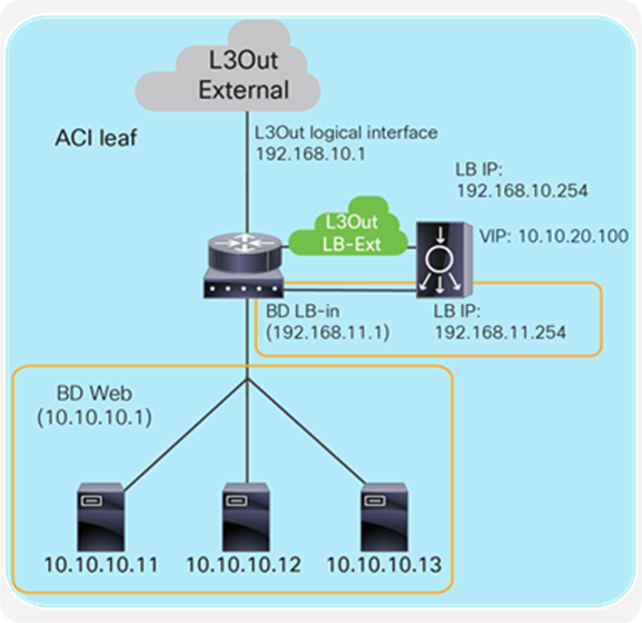
Figure 17 provides an example of this setup. The VIP 10.10.20.100 is outside of the load balancer external interface local subnet, 192.168.10.0/24. ACI L3Out “LB-Ext” for the load balancer external interface connectivity is used to add the route on the ACI fabric to reach VIP 10.10.20.100 via 192.168.10.254, which is the load balancer external interface IP. If RHI is enabled on the load balancer, use of dynamic routing on the L3Out “LB-Ext” is required to establish dynamic routing peering between the ACI border leaf node and the load balancer.
Either SNAT or PBR can be used to make the return traffic go through the load balancer. If PBR is used to redirect return traffic (from the provider “Web” EPG to the consumer L3Out EPG “External” for an external network) to the load balancer internal interface, it requires the unidirectional PBR feature that is available in Cisco APIC Release 5.0.
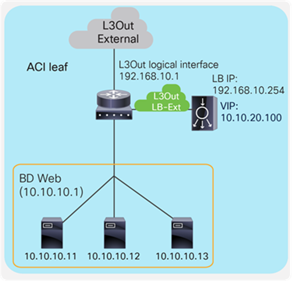
One-arm load balancer with fabric as gateway
If L3Out “LB-Ext” is used for one-arm load balancer connectivity, the servers and the load balancer interface should be in different subnets because the servers would also need to be in the same L3Out.
Figure 18 provides an example of what this looks like. The VIP 10.10.20.100 is outside the load balancer interface local subnet, 192.168.10.0/24. The L3Out “LB-Ext” for the load balancer interface is used to add the route on the ACI fabric to reach VIP 10.10.20.100 via 192.168.10.254, which is the load balancer interface IP. If RHI is enabled on the load balancer, use of dynamic routing on the L3Out “LB-Ext” is required to establish dynamic routing peering between the ACI border leaf nodes and the load balancer.
As of APIC Release 5.0, ACI PBR can redirect traffic to a load balancer interface that is connected to a bridge domain, and not the interface on an L3Out. Therefore, SNAT must be enabled on the load balancer.
This section explains the following Cisco design considerations, which can be applied to the design options already discussed in this document:
● Choice of high-availability (HA) and failover mode
● Choosing whether to configure the Cisco interface with a floating MAC (virtual MAC)
● Choosing to route traffic based on the ARP resolution on the next hop or from the MAC learned on the incoming traffic with the Return to Last Hop feature, also known as source MAC-based forwarding.
● Whether to enable Link Layer Discovery Protocol (LLDP) on the Secure ADC
● Tuning IP aging on ACI
High availability (HA)
High availability is provided by installing redundant appliances either of physical or virtual type. A redundant system consists of two identical devices, with almost identical configuration. When an event occurs that prevents one of the Secure ADC devices from processing network traffic, the peer device in the redundant system immediately begins processing that traffic, and users experience no interruption in service as the session state is maintained between the two systems.
You can configure the devices of a redundant system to run in one of two redundancy modes: active/standby mode and active/active mode.
Active/standby mode
With active/standby mode, only one of the two devices is in an active state that is processing traffic at any given time. The inactive device serves strictly as a standby device, becoming active only if the active device becomes unavailable. When a standby device becomes active, it normally remains active until an event occurs that requires the other device to become active again, or until you specifically force it into a standby state. Active/standby mode is the recommended mode for redundant system configuration, because there is no chance of overwhelming a device as it has been sized to handle all traffic through a single appliance.
Active/active mode
With active/active mode, both devices are in an active state simultaneously; each device processes traffic for different virtual servers (VIPs) or SNATs. If an event prevents one of the devices from processing traffic, the other device begins processing that traffic in addition to its own. In this mode, both devices actively process application traffic, each for a different application.
There are two methods to provide active/active configuration on the Cisco Secure ADC. One is by the use of Service Groups, known as Service HA. The other option is by enabling multiple virtual instances of the ADC on each platform, known as vADC.
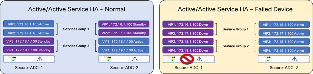
Active/active mode Service HA
A Service HA is made up of one or more Service Groups. Service Groups are collections of VIPs and floating IP addresses that move between Cisco Secure ADC in a high-availability failover event. The other Secure ADC device in the HA pair processes its application traffic using a second Service Group. If one of the devices becomes unavailable for any reason, the other device automatically begins processing traffic for the unavailable peer device, while continuing to process the traffic for its own application.
The first diagram of Figure 20 provides an example of the Service HA, with two Secure ADCs, Secure-ADC-1 and Secure-ADC-2. Each Secure ADC contains a Service Group, which is active, with another service group that is backing up the active Service Group on the alternate Secure ADC.
When a device becomes unavailable, the active ADC will change the state of the VIP and Floating IPs that were previously in a standby state to active. Now all traffic will be handled by Secure-ADC-2.
Active/active mode using vADCs
Another option to achieve an active/active mode is by creating multiple virtual instances of ADC on the device. these are known as vADCs. Applications or groups of applications are deployed in the vADC instance. Similar to active/active with Service HA, some applications are primary on one vADC1 on Secure-ADC-1, while others are primary on vADC2 on Secure-ADC-2. The HA configuration is similar to the active/standby mode described earlier. This can be seen in the second diagram in Figure 20. Each vADC pair, which is comprised of a vADC active on one device and vADC backup on another device, is assigned a unique HA ID. This HA ID will be used to identify the packets for each pair of vADCs for vADC health and session synchronization.
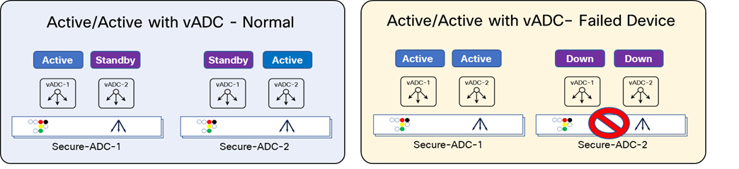
Note: A failure can occur on either ADC 1 or ADC 2 in an Active-Active scenario. The upper-right diagram shows a failure on ADC 1 while the bottom-right diagram shows a failure on ADC 2.
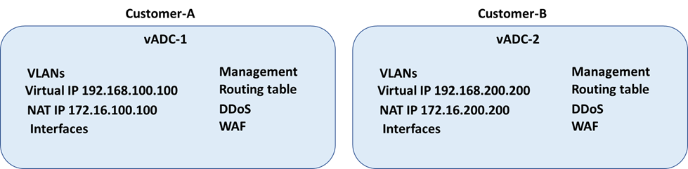
vADCs provide more flexibility, as each vADC on an appliance acts as an independent device, including its own dedicated interfaces, VLANs, IP address space, routing domain, management, and so on. This provides complete segregation from the underlying physical ADC and other vADCs. One of the key benefits for this is administration. One vADC can be managed by one team, while the other vADC is managed by another.
By implementing this configuration, you ensure that:
● Any objects on a Secure ADC device that you configure for synchronization remain synchronized between the two devices.
● Failover capability and connection mirroring are enabled on each device.
Some considerations while deploying an active/active mode is that an active/active architecture can be helpful in the case of high load over an active/standby architecture. The drawback is that if you lose one of your devices, the other one may not be able to cope with complete traffic load. In terms of functionality, the software module supports active/active mode, but the combined performance of both active/active device failing back to a single device may not and provide additional challenges when one device fails. For this reason, even in an active/active mode, the maximum recommended performance should never exceed 50% of the performance of a single device.
Failover and session mirroring
To enable a device to fail over to its peer device, you must first specify the type of failover that you want the redundant system to use.
There are two possible methods to monitor the health and session mirroring; one is to use a dedicated interswitch link, and the other is to use network based. Network-based leverages the data path interfaces to provide health and session mirroring.
Interswitch links
An interswitch link is a direct connection between two Secure ADCs that is used for session mirroring and to send health checks. Both the active and backup devices will monitor the health of the other device to allow for fast failover without traffic interruptions. When using active/active mode with vADC, that same interswitch link can be leveraged and each pair of matching vADC messages are uniquely identified by the HA ID, which is unique per the vADC pair.
Network failover
When you configure network failover, you enable failover by configuring your redundant system to use the network to determine the status of the active device. You can use network failover in addition to, or instead of, interswitch link failover.
On the Secure ADC, multiple interfaces can be used to decide if the network failover should occur. Configuring failover requires you to specify peer IP addresses and floating IPs on each device. Some of these IP addresses enable continual, high-availability (HA) communication among devices in the device group, while other addresses ensure that application traffic processing continues when failover occurs.
The types of IP addresses on each Secure ADC device that can be used for network failover are:
● A local, static ADC-IP address for VLAN “HA.” This unicast ADC-IP address is the main address that other devices in the device use to communicate continually with the local device to assess the health of that device. When a device in the device group fails to receive a response from the local device, the Secure ADC system triggers failover.
● A local management IP address. This unicast management IP address serves the same purpose as the static ADC-IP address for group VLAN “HA,” but it is only used when the local device is unreachable through the “HA” static ADC-IP address.
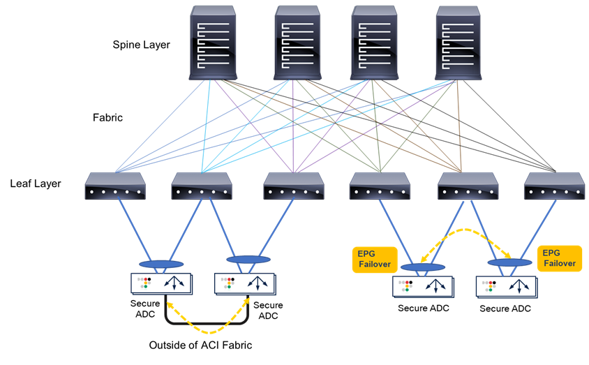
In the case of using network failover for HA on the Secure ADC with ACI (Figure 22), if the network failover traffic is carried outside of the Cisco ACI fabric (for example, when using interfaces that are connected to each Secure ADC device directly), the Cisco ACI fabric doesn’t have to manage the failover network. If the network failover traffic is carried within the Cisco ACI fabric, an EPG will need to be configured for the failover traffic.
For general Secure ADC HA considerations and configuration, refer to the following documents:
● HA – https://support.cisco.com/HA
● ADC Session Mirroring – https://support.cisco.com/session_mirroring
Endpoint movements during failover
When failover takes place, the newly active Secure ADC sends Gratuitous Address Resolution Protocol (GARP) for floating ADC-IPs and VIPs. This is done so that endpoints and network devices in the same broadcast domain can update the ARP table and MAC address table. The ACI fabric has “Move Frequency (per second)” configuration in “Endpoint Retention Policy” that is referred from bridge domains to limit the maximum number of endpoint moves allowed per second in the bridge domain. The number is counted as total movements of any endpoint in the given bridge domain, whether it is a single endpoint flap, a simultaneous move of multiple endpoints, or a combination of both. If the number of movements per second is exceeded, the “Move Frequency” (256 by default) and the “Hold Interval” (300 seconds by default) will trigger, and the learning new endpoint in the bridge domain is disabled until the “Hold Interval” expires. This feature is called BD Move Frequency or Endpoint Move Dampening. If there are many IP addresses in a bridge domain that are expected to move at the same time, for example, Secure ADC owns many IPs in a given bridge domain, you might need to increase the “Move Frequency” to prevent endpoint learning from being disabled in the bridge domain. The APIC configuration location for “End Point Retention Policy” is at Tenant > Policies > Protocol > End Point Retention, which is referred from bridge domains.
The other option to prevent endpoint learning from being disabled in the bridge domain is to enable “Rogue EP Control.” If the Rogue EP Control is enabled, Endpoint Move Dampening via Endpoint Retention Policy explained above will not take effect. The APIC configuration location for “Rogue EP Control” is at System > System Settings > Endpoint Controls > Rogue EP Control. This configuration is a fabric-wide setting and is disabled by default.
For more details on ACI endpoint learning behavior and the configurations above, refer to the “Endpoint Retention Policy” and “Rogue EP Control” sections in the ACI Fabric Endpoint Learning White Paper: www.cisco.com/c/en/us/solutions/collateral/data-center-virtualization/application-centric-infrastructure/white-paper-c11-739989.html.
Another scenario possible after Secure ADC failover takes place is that the new standby Secure ADC still sends traffic using floating ADC-IPs and VIPs as source IP addresses. This will result in the ACI fabric learning the IPs from multiple locations via the data plane. This issue can be avoided by disabling IP Data-plane Learning.
For more details on ACI IP Data-plane Learning and its use case, refer to the “IP Data-plane Learning” section in the ACI Fabric Endpoint Learning White Paper: www.cisco.com/c/en/us/solutions/collateral/data-center-virtualization/application-centric-infrastructure/white-paper-c11-739989.html#IPDataplaneLearning.
Virtual MAC
Virtual MAC is a feature that allows you to manually allocate a MAC address to a traffic group across a Secure ADC pair configured for high availability. More specifically, this MAC address floats between the devices in an HA pair, along with the floating ADC-IPs and virtual addresses within the same traffic group.
It’s highly recommended to use virtual MAC under the following conditions:
● To improve reliability and failover speed in lossy networks by minimizing Address Resolution Protocol (ARP) table updates on servers and network devices that are in the same broadcast domain with Secure ADC system
● When using Policy-Based Redirect (PBR) on Cisco ACI
When configuring traffic-group Virtual MAC for Secure ADC on VMware ESXi servers, you must configure the virtual switch’s Forged Transmits and Promiscuous Mode settings to Accept. By default, the Promiscuous Mode and Forged Transmits settings are disabled. Since the VMM integration with the Cisco APIC, the port-group security settings are controlled by the APIC and cannot be changed directly on VMware vCenter or ESXi servers. The APIC settings for the port-group security settings are available at the domain association configuration under an EPG.
To learn more about Layer 4 to Layer 7 services configuration, visit: www.cisco.com/c/en/us/support/cloud-systems-management/application-policy-infrastructure-controller-apic/tsd-products-support-series-home.html.
Return to Last Hop
The Return to Last Hop setting allows the Secure ADC to track the source MAC address of incoming connections and return traffic from pools to the source MAC address, regardless of the routing table.
When enabled, Return to Last Hop allows the Secure ADC system to send return traffic from pools to the MAC address that transmitted the request, even if the routing table points to a different network or interface. As a result, the Secure ADC system can send return traffic to clients, even when there is no matching route. An example would be when the Secure ADC system does not have a default route configured and the client is located on a remote network. Additionally, Return to Last Hop is useful when the Secure ADC system is load-balancing transparent devices that do not modify the source IP address of the packet. Without the Return to Last Hop option enabled, the Secure ADC system may not return connections to the same transparent node, resulting in asymmetric routing.
For more details on Return to Last Hop refer to https://support.Cisco.com/csp/InboundTraffic.
If ACI PBR is used and Return to Last Hop is enabled, “Source MAC Rewrite” might need to be enabled on ACI PBR. Otherwise, the Secure ADC will use the original source MAC address, instead of the ACI bridge domain MAC, as the destination MAC for return traffic, even if the next hop of the traffic should be the ACI bridge domain MAC. See the Cisco ACI PBR white paper for more detail: www.cisco.com/c/en/us/solutions/collateral/data-center-virtualization/application-centric-infrastructure/white-paper-c11-739971.html.
Link Layer Discovery Protocol (LLDP)
Consider configuring LLDP on the Secure ADC device and the APIC for the interface between the Secure ADC and the ACI leaf nodes. LLDP provides the Secure ADC system with the ability to advertise its identity and capabilities to the ACI network. Once the ACI network has the information about the Secure ADC interface, integrations like the Secure ADC ACI ServiceCenter (discussed later in this document) will be able to use this information to build out a topology map.
IP Aging on ACI
Because of the nature of the load balancer that owns multiple IPs with a single MAC address, it is recommended to enable “IP Aging” on ACI. The APIC configuration location for IP Aging is at System > System Settings > IP Aging. The default setting is disabled.
If IP Aging is disabled, an endpoint might have unused IP addresses stuck on the same MAC address. For example, when VIPs are using the same MAC as the ADC-IP, when Secure ADC is added and then the VIP is deleted as shown in Figure 23, the ACI fabric keeps the entry for the VIP that was already deleted as long traffic is received from the MAC. It is because the ACI fabric sees the endpoint as all three components (the MAC, ADC-IP, and VIP). If traffic is received from any one of these components, the entries for all three will be kept active.
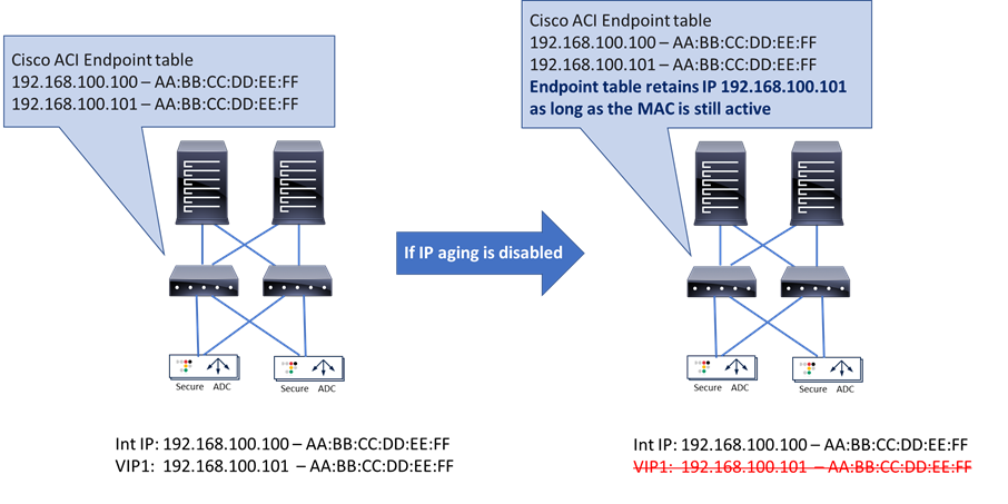
If IP Aging is enabled, the ACI fabric sends a unicast ARP packet at 75 percent of the configured endpoint retention timer for all IP addresses that belong to the endpoint. If no response is received from that particular IP address, it will be aged out of the endpoint table. (Note that the MAC address and responding IP address for the endpoint will be retained).
This section explains multitenant design examples and considerations on ACI and Secure ADC.
ACI multitenant design
This section explains the following ACI multitenant capabilities:
● Role-Based Access Control (RBAC) to create separate users for each tenant
● Network isolation for each tenant
● Security isolation for each tenant
● Allowing communication between tenants
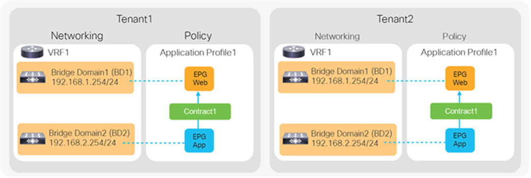
A tenant in the ACI object model represents the highest level object. A tenant consists of networking-related objects such as VRFs, bridge domains and subnets, and policy-related objects such as application profiles, EPGs, and contracts, as shown in Figure 24. A tenant could be a unique customer, an operating group, a business device, an application, etc.
As of Release 4.2(3) of Cisco APIC, an ACI fabric supports up to 3000 tenants and 3000 VRFs. Refer to the ACI-verified scalability guide for the latest status: www.cisco.com/c/en/us/support/cloud-systems-management/application-policy-infrastructure-controller-apic/tsd-products-support-series-home.html.
Role-Based Access Control (RBAC)
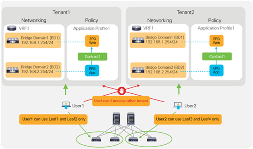
By using ACI RBAC, an administrator can give tenant users access to their own tenant only. For example, User1 can write and read objects in Tenant1 only and User2 can write and read objects in Tenant2 only. Starting from APIC Release 5.0, the introduction of the Leaf RBAC feature allows an administrator to let users use specific leaf nodes only. For example, User1 for Tenant1 can use Leaf1 and Leaf2 only, and User2 for Tenant2 can use Leaf3 and Leaf4 only. This is useful for allocating isolated logical networks and physical resources to different purposes in a multitenant environment (see Figure 25).
Network isolation
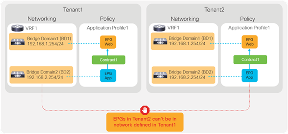
Objects such as VRFs, BDs, EPGs, and contracts defined in a tenant are not visible from other tenants unless objects are defined in a common tenant. Thus, the typical multitenant design is deployed so that each tenant has unique VRFs and BDs (Figure 26). The result is that EPGs in different tenants can’t be in the same network (VRF/BD), which means each tenant network is logically isolated, even though both VRFs are deployed in the same ACI fabric.
Security isolation
Another example is the use of VRFs/BDs defined in common (Figure 27). This allows EPGs in different tenants to be in the same network. However, they still can’t talk each other unless a contract is defined between them.
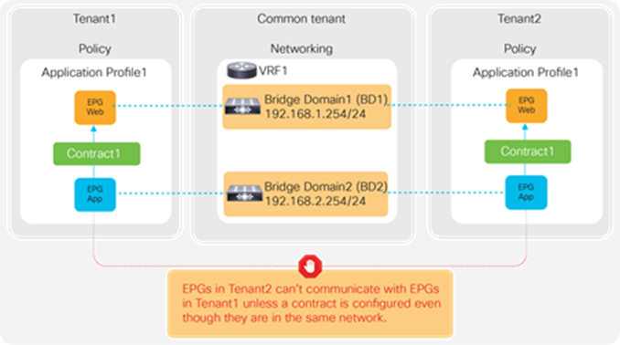
EPGs in different tenants can’t have a contract unless a contract is exported from the provider tenant to the consumer tenant, or a contract defined in a common tenant is used.
Secure ADC multitenant design
This section explains Secure ADC multitenant design.
Virtual ADC (vADC)
The Secure ADC has the capability to run a hypervisor known as ADC-VX. ADC-VX is built on a unique architecture that virtualizes the OnDemand Switch resources—including CPU, memory, network, and acceleration resources. This specialized hypervisor runs fully functional virtual ADC instances, each of which delivers ADC functionality just like a dedicated physical ADC. Each virtual ADC instance contains a complete and separated environment of resources, configurations, routing table, and management.
A vADC is a virtualized instance of the OS that behaves in the same manner as a traditional hardware ADC, with the exception that while it is bound to a specific hardware resource, the amount of resources allocated to the vADC may vary based on the user’s or application’s resource needs. This enables you to run multiple independent and private vADCs that vary in their processing power. Each vADC comprises a vSP (Virtualized Switch Processor) and a vMP (Virtualized Management Processor), providing the vADCs with their own set of resources, network infrastructure, and services that are completely independent of neighboring vADCs. This enables multiple users to run vADCs and allocate resources to these vADCs without introducing any risk to the other vADCs within the shared physical environment.
vADC Domain
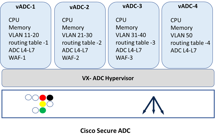
vADC Domain creates a strictly defined set of resources including a routing table. Each vADC Domain contains IP address spaces, routing information, and VLANs. IP address spaces can be duplicated between domains, allowing easy reuse of RFC 1918 private addressing for multiple customers or projects. Route domains can be strictly isolated from one another or have explicitly controlled access between them. This allows a common “front-end” network space to be presented to an access network but with services running within dedicated “tenant” network spaces. System resources are explicitly dedicated for each domain, ensuring that performance and SLA can be guaranteed. This design allows for the most efficient use of system resources since each domain will consume only the resources it is allocated (see Figure 29).
Global Administrator
The Global Administrator is a superuser that works at a management level above and separate from a vADC Administrator. The Global Administrator manages the physical Secure ADC resources and uses the physical devices in a data center, is responsible for creating vADC instances, and manages and monitors both system and vADC resource allocation and utilization. The Global Administrator does not manage Layer 3 or server load balancing functionality, but rather they are managed by the vADC Administrator.
The Global Administrator is responsible for:
● Managing vADC creation and deletion
● Monitoring health and resource usage
● Allocating processing power
● Assigned initial user access for vADC
● Configuring and maintaining management ports
● Delegating system services
● Synchronized vADC
vADC Administrator
The vADC Administrator manages Layer 3 and server load balancing functionality, controlling the service and/or application policies and performance.
vADC Administrator tasks are:
● Configuring the vADC
● Interface configuration
● The creation and management of vADC specific users
● Routing
● Virtual services
● NAT
User role
A user role is a property of a Secure ADC administrative user account. For each Secure ADC user account, you can assign a different user role to each vADC to which the user has access. This allows multiple user roles to be assigned to each user account on the system.
The tasks that a user can perform are based on the user role assigned. For example, a user with the operator role can view settings but not change any setting. Conversely, a user with the administrator role can perform all tasks related to objects within the related administrator role specified. The Secure ADC system offers several different user roles that you can choose from when assigning roles to a user account. Each user role grants a different level and type of permissions to the user.
Note: You must have an administrator user role to assign user roles to user accounts.
Management ports ACI and Secure ADC multitenancy
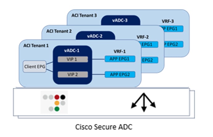
Based on different considerations defined above for multitenancy, one way of combining the two technologies is to use a single Secure ADC appliance and leverage vADC (see Figure 30):
● A tenant on ACI is mapped to a vADC on the Secure ADC
● A VRF on ACI is mapped to a vADC that has its own unique routing table
Another method to achieve multitenancy, which includes appliance-based separation along with administrative and network separation, is to use a dedicated Secure ADC device per APIC tenant.
● A tenant on APIC can be mapped to a dedicated Secure ADC virtual appliance.
This section explains troubleshooting tips for the load balancer connected to the Cisco ACI fabric.
ACI troubleshooting
For more details about ACI forwarding and policy troubleshooting, see the Cisco ACI Troubleshooting Guide: www.cisco.com/c/dam/en/us/td/docs/switches/datacenter/aci/apic/sw/4-x/troubleshooting/Cisco_TroubleshootingApplicationCentricInfrastructureSecondEdition.pdf.
The PBR section in the document includes a traffic flow example for the load balancer.
Secure ADC troubleshooting
For Secure ADC troubleshooting and technical support, please contact Cisco.
Cisco Secure ADC Data Sheet: www.cisco.com/c/en/us/products/collateral/security/secure-adc-alteon-ds.html
Cisco Secure ADC Technical Specifications: www.cisco.com/c/en/us/products/collateral/security/alteon-technical-specs-ds.html
Cisco ACI white papers: www.cisco.com/c/en/us/solutions/data-center-virtualization/application-centric-infrastructure/white-paper-listing.html
Cisco Secure ADC on Sales Connect (CCO login required): https://salesconnect.cisco.com/#/program/PAGE-13864