Cisco 4G LTE Advanced Pro, 4G LTEA, 4G LTE, and 3G Omnidirectional Dipole Antenna Data Sheet
Available Languages
Bias-Free Language
The documentation set for this product strives to use bias-free language. For the purposes of this documentation set, bias-free is defined as language that does not imply discrimination based on age, disability, gender, racial identity, ethnic identity, sexual orientation, socioeconomic status, and intersectionality. Exceptions may be present in the documentation due to language that is hardcoded in the user interfaces of the product software, language used based on RFP documentation, or language that is used by a referenced third-party product. Learn more about how Cisco is using Inclusive Language.
This document provides the description, supported features, and installation instructions for the Cisco 4G LTEAP, 4G LTEA, 4G LTE, and 3G Omnidirectional Dipole Antenna (LTE-ANTM2-SMA-D).
Caution: Read the information in Safety Instructions, page 11, before installing or replacing antennas.
The LTE-ANTM2-SMA-D omnidirectional dipole antenna is designed for indoor use with Cisco 4G Long Term Evolution (LTE), Long Term Evolution Advanced (LTEA), and Long Term Evolution Advanced Pro (LTEAP) Integrated Services Routers (ISRs) and pluggable modules with a SubMiniature version A (SMA) connector. The antenna is marked with a dual green band to indicate that it supports Cisco LTEA routers and modules.
This antenna has the following features:
● Support for frequencies of 617 to 960, 1400 to 1700, 1710 to 2960, 3400 to 3900, and 5150 to 6000 MHz.
● Standalone antenna peak gain of -2~8 dBi in the supported frequency bands.
● Articulating joint that can maneuver into three stop positions: 0°, 45°, and 90°.
● Male SMA connector that allows direct mounting of the antenna to any supported Cisco router or pluggable module with an SMA connector.
● The SMA connector design has added rotational frictional torque to ensure that the SMA interface stays properly mated, and to reduce chances of a disconnect. The design is also more finger friendly compared to a classic SMA hex nut design.
For optimal performance, we strongly recommend that you use two antennas to take full advantage of Multiple-Input, Multiple-Output (MIMO) technology on all Cisco cellular routers that support MIMO (4G LTE and later releases).
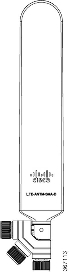
Cisco LTE-ANTM2-SMA-D omnidirectional dipole antenna, SMA connector, and articulating joint
Table 1. Antenna specifications
| Operating frequencies |
617 to 960 MHz 1400 to 1700 MHz 1710 to 2690 MHz 3400 to 3900 MHz 5150 to 6000 MHz |
| Polarization |
Vertical |
| Nominal impedance |
50 Ohms |
| Peak gain |
0 dBi (617 to 960 MHz) 2 dBi (1400 to 2960 MHz) 5 dBi (3400 to 3900 MHz) 5 dBi (2500 to 2690 MHz) Note: The standalone antenna peak gain numbers are provided above. When you install an antenna close to metallic objects or directly on the chassis, the peak gain will be affected. We recommend that you keep antennas away from very large chassis and metallic objects. You can install antennas directly on smaller or medium-sized chassis. In all cases, we recommend that you keep different antennas away from each other and from various known sources of electromagnetic radiation. |
| Voltage Standing Wave Ratio (VSWR) |
4.5:1 (698 to 960 MHz) 4:1 (1400 to 2960 MHz) 4:1 (3400 to 3900 MHz) 4:1 (5150 to 6000 MHz) |
| Maximum RF input power |
3W |
| DC power |
No DC power required for antenna operation. |
| Dimensions (L x W x D) |
9 x 1.2 x 0.35 in. (229 x 30.5 x 8.96 mm) |
| Weight |
1.8 oz (50 g) |
| Efficiency |
The LTE-ANTM2-SMA-D antenna has high standalone efficiency and maintains high efficiency when installed directly on the front plate of a small or medium-sized Cisco router. However, depending on chassis size and a variety of other electromagnetic considerations, installing the antenna directly on the chassis is not always recommended. |
| Temperature range |
-40° to +185°F (-40° to +85°C) (operating temperature) -40° to +185°F (-40° to +85°C) (storage temperature) |
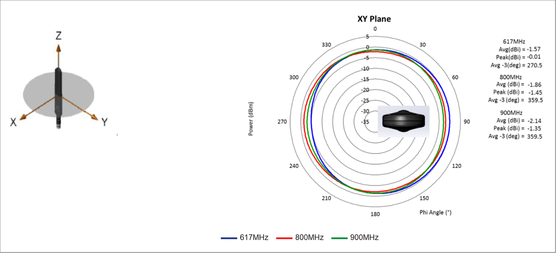
617-, 800-, and 900-MHz cellular antenna radiation patterns (dBi), azimuth
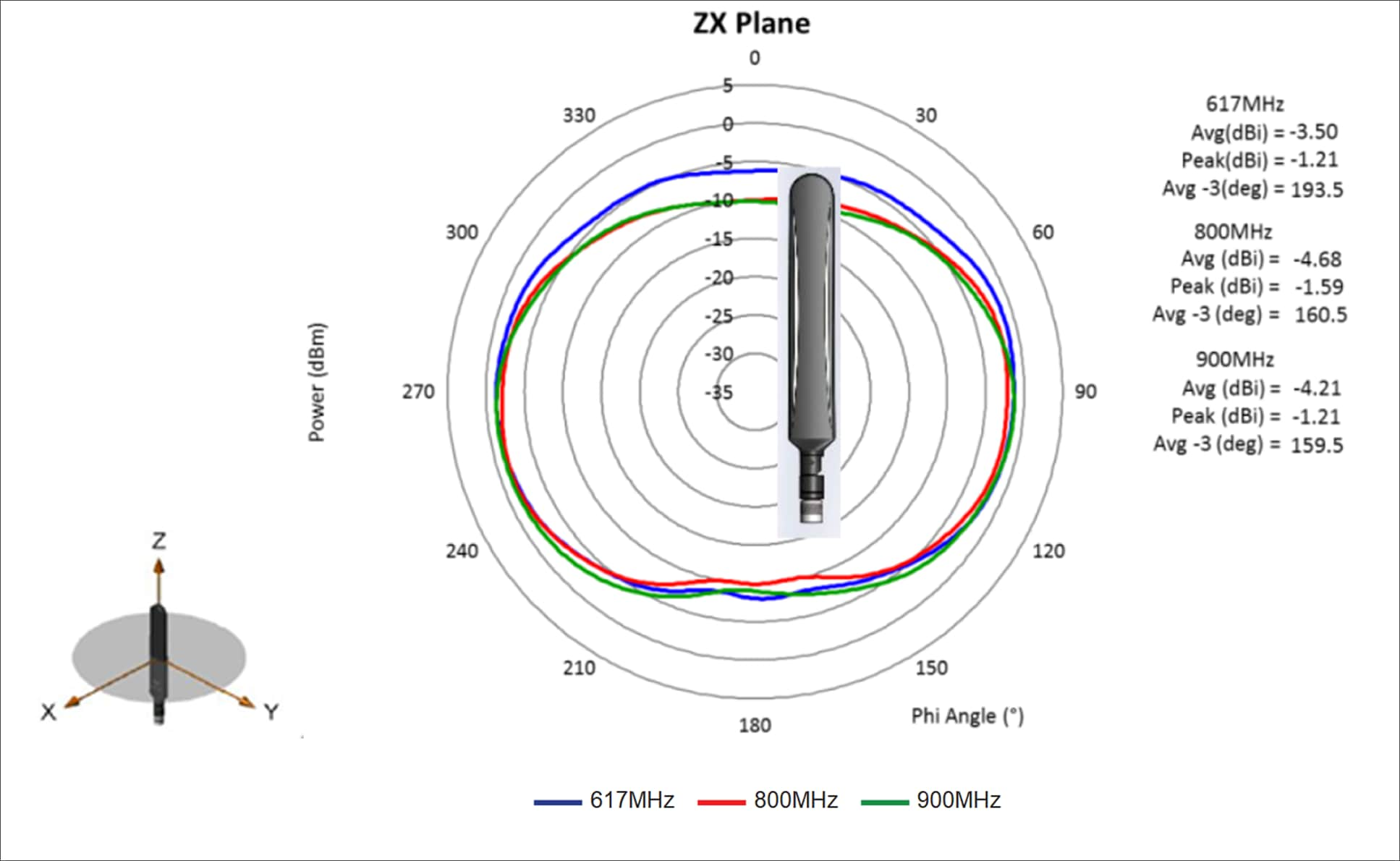
617-, 800-, and 900-MHz cellular antenna radiation patterns (dBi), elevation, Phi = 0
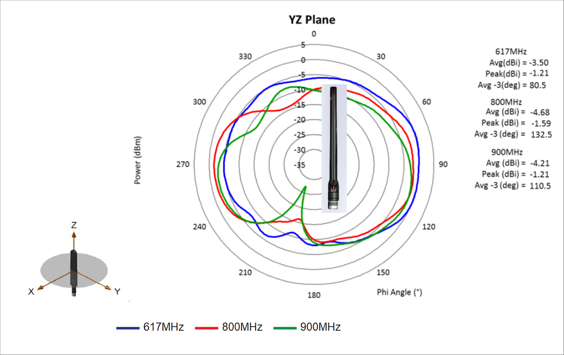
617-, 800-, and 900-MHz cellular antenna radiation patterns (dBi), elevation, Phi = 90
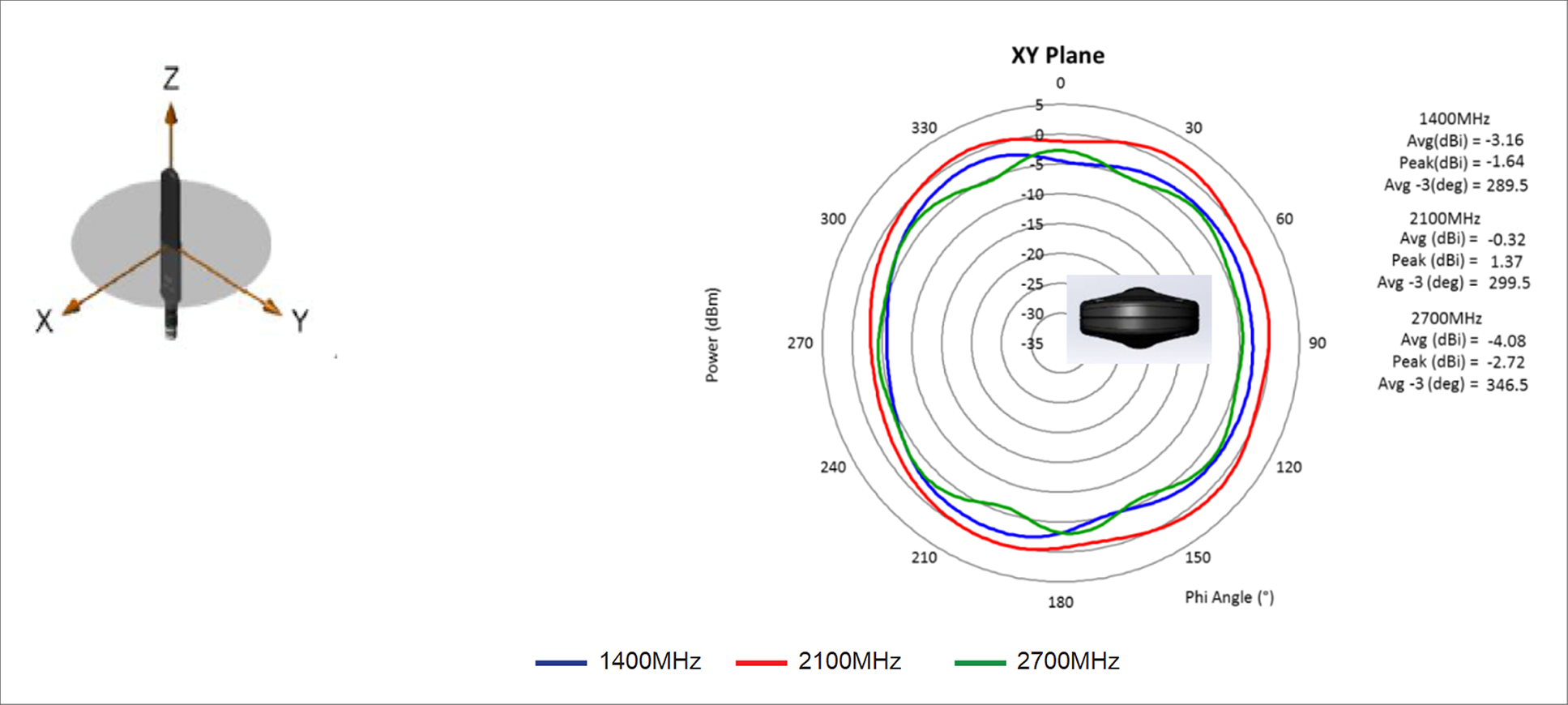
1400-, 2100-, and 2700-MHz antenna radiation patterns (dBi), azimuth
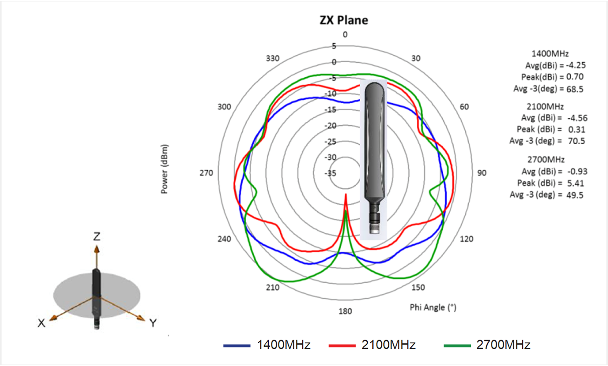
1400-, 2100-, and 2700-MHz antenna radiation patterns (dBi), elevation, Phi = 0
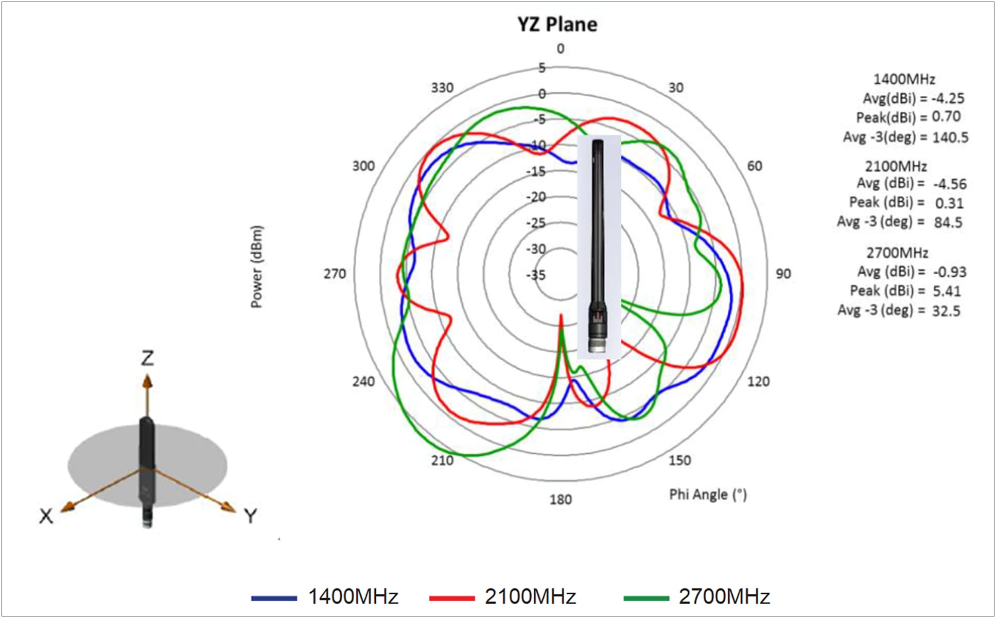
1400-, 2100-, and 2700-MHz antenna radiation patterns (dBi), elevation, Phi = 90
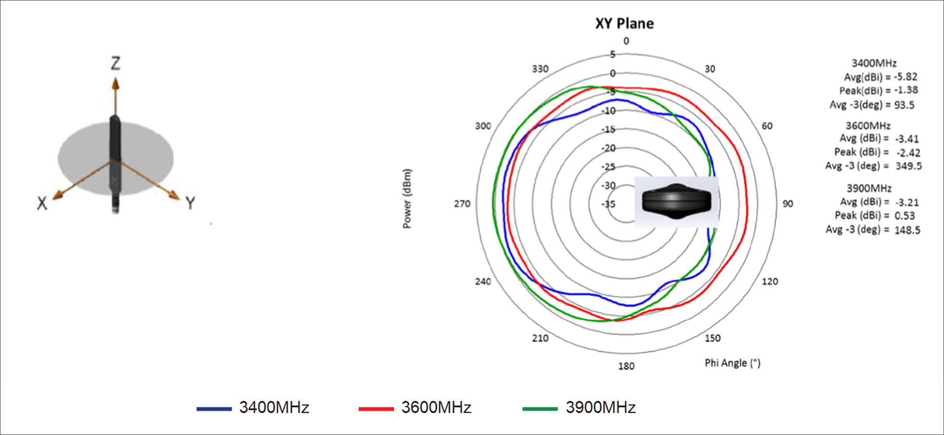
3400-, 3600-, and 3900-MHz cellular antenna radiation pattern (dBi), azimuth
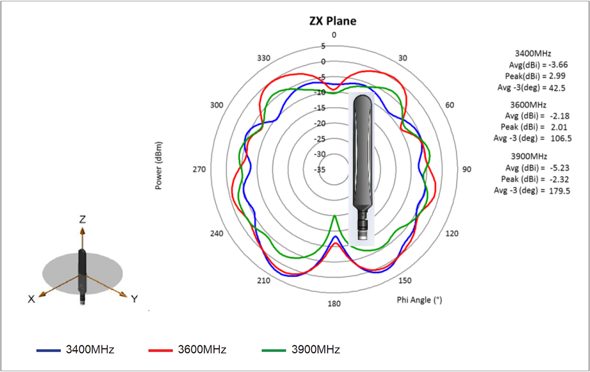
3400-, 3600-, and 3900-MHz cellular antenna radiation pattern (dBi), elevation, Phi = 0
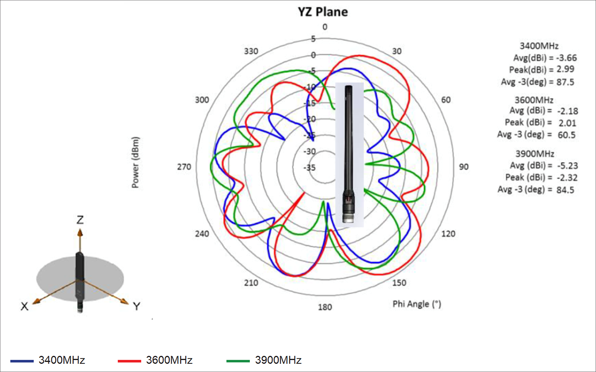
3400-, 3600-, and 3900-MHz cellular antenna radiation pattern (dBi), elevation, Phi = 90
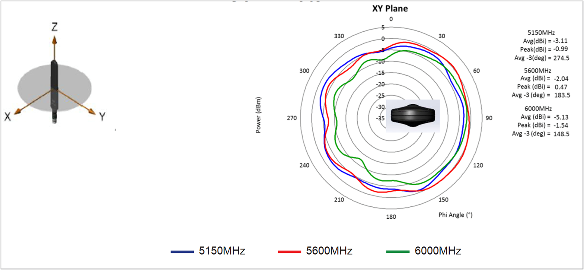
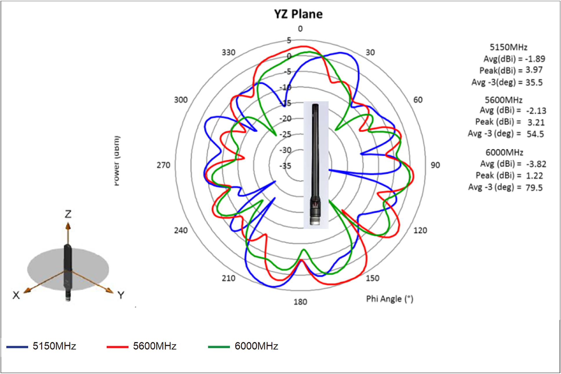
5150-, 5600-, and 6000-MHz cellular antenna radiation pattern (dBi), azimuth
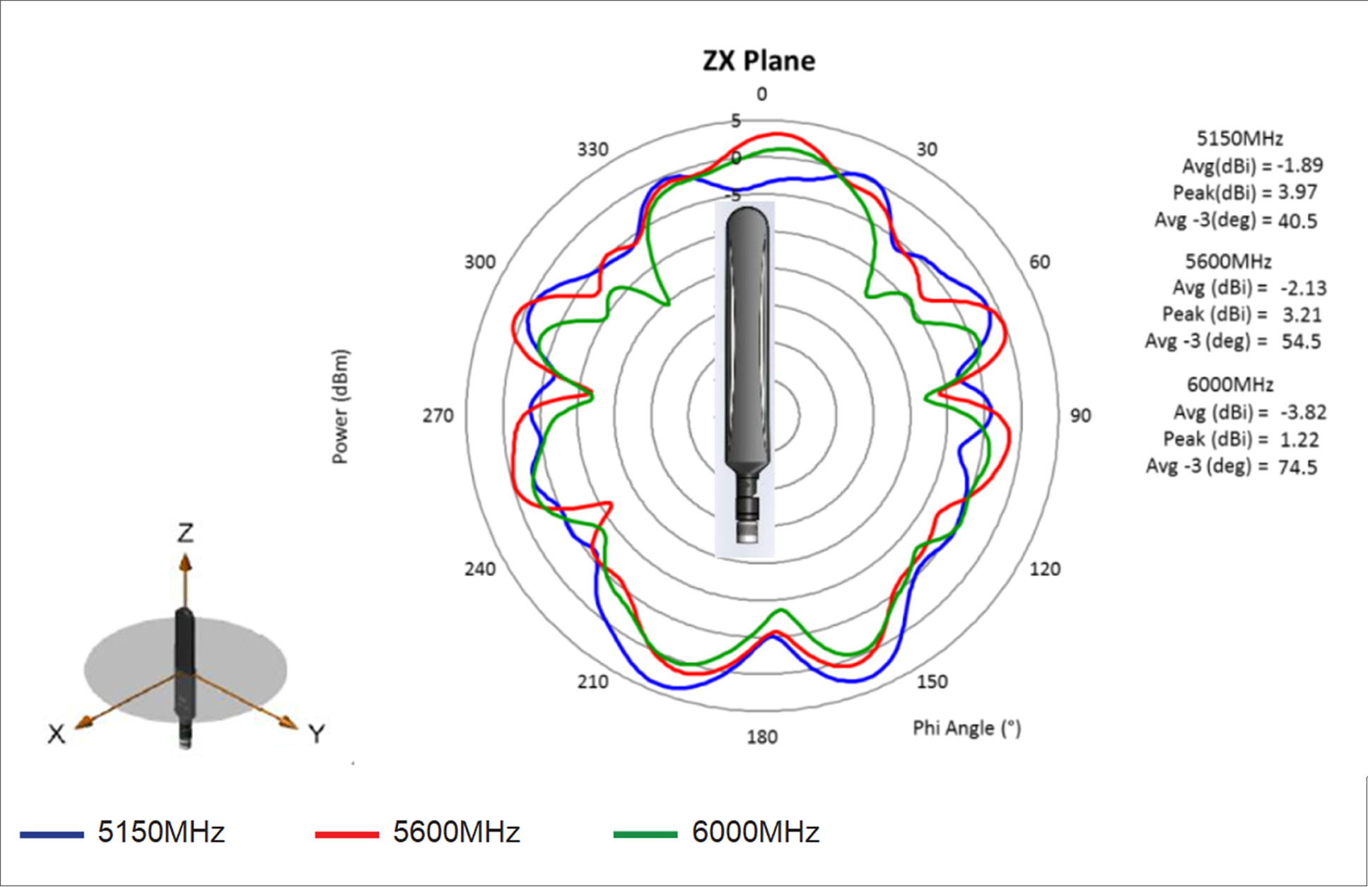
5150-, 5600-, and 6000-MHz cellular antenna radiation pattern (dBi), elevation, Phi = 0
5150-, 5600-, and 6000-MHz cellular antenna radiation pattern (dBi), elevation, Phi = 90
Warning: Important safety instructions
A warning means danger. You are in a situation that could cause bodily injury. Before you work on any equipment, be aware of the hazards involved with electrical circuitry and be familiar with standard practices for preventing accidents.
Save these instructions
Follow these safety instructions when installing the antenna.
Antenna installation warning
Warning: In order to comply with FCC Radio Frequency (RF) exposure limits, antennas should be located at a minimum of 7.9 inches (20 cm) or more from the body of all persons.
Warning: When installing or replacing the unit, the ground connection must always be made first and disconnected last.
Caution: Do not install the antenna in an outdoor environment.
Caution: For your physical safety, and to help you install your antenna successfully, follow these safety precautions.
● Plan your installation procedure carefully and completely before you begin.
● Choose your installation site with both safety and performance in mind.
● If you are installing an antenna for the first time, for your own safety as well as others, seek professional assistance. Your Cisco sales representative can explain which mounting method to use for the size and type of antenna you are about to install.
● Before you install an antenna, contact your Cisco account representative to learn which mounting method to use for the size and type of antenna you are about to install.
The following section contains information for installing the LTE-ANTM-SMA-D antenna.
This antenna is designed to be mounted either directly or on an antenna extension stand to any Cisco 3G/4G wireless ISR, LTE, LTEA, or LTEAP router with an SMA(f) connector by threading it onto the mating connector. Refer to the router’s technical documentation for recommendations on direct mounting of the antenna to the router versus installing the antenna on an antenna extension stand. Mount and deploy the antenna at the 0° position, 45° position, or 90° position, and then change that position at will. The rotation of the antenna into the proper position can take place while the antenna is still loose on the mating connector. No software is required for this installation.
In addition to the antenna orientation, the installation location of 4G routers and cellular modules plays a significant role in determining overall network performance. Routers located at the farthest coverage points might have 10 to 50 percent of the bandwidth available compared to routers located closer to the cellular base station tower.
Because antennas transmit and receive radio signals, their performance can be adversely affected by the surrounding environment, including physical obstructions. Radio frequency (RF) interference may occur between wireless systems located close to each other, especially if the antennas of these systems are located close to each other.
Follow these guidelines to ensure the best possible performance:
● When you use the antenna on a modular router with an LTE pluggable module, always mount the antenna on an appropriate extension cable and antenna stand. The antenna performance, and therefore that of the router, will not be optimal if mounted directly to the pluggable module.
● Mounting of the antenna directly to smaller physical size routers is allowed.
● For optimal performance, space multiple antennas apart by at least 17 inches (43 cm).
● The lowest LTE frequency of 700 MHz, or 17 inches, represents 1 wavelength. Spacing of 0.5 wavelength, or 8.5 inches, (22.5 cm) results in good performance.
● Spacing of less than 8.5 inches may result in significantly reduced MIMO performance.
● Spacing antennas close to each other (e.g. 3 inches) results in antennas detuning from their original designed performance due to antenna coupling.
● Wherever possible, mount the ISR cellular router or the pluggable LTE module and antenna where the cellular base station or tower are within sight and without physical obstructions. Barriers along the line of sight between the device and the local base station will degrade the wireless radio signals. Install ISR cellular routers, pluggable modules, and antennas above floor level in office environments or near the ceiling for better performance because most obstructions tend to be near the floor level.
● The density of the materials used in a building’s construction determines the number of walls the signal must pass through while still maintaining adequate coverage. Consider the following before choosing the location for installing your antenna:
◦ Paper and vinyl walls have very little effect on signal penetration.
◦ Solid and precast concrete walls limit signal penetration to one or two walls without degradation of coverage.
◦ Concrete and wood block walls limit signal penetration to three or four walls.
◦ A signal can penetrate five or six walls constructed of drywall or wood.
◦ A thick metal wall or wire-mesh stucco wall causes signals to reflect back and causes poor penetration.
● Avoid mounting the antenna next to a column or vertical support that could create a shadow zone and reduce the coverage area.
● Keep the antenna away from reflective metal objects such as heating and air-conditioning ducts, large ceiling trusses, building superstructures, and major power cabling runs. If necessary, use an extension cable to relocate the antenna away from these obstructions.
● For information about antennas and modules, see: https://www.cisco.com/go/cg-modules
● For information about omnidirectional and directional antennas, see: https://www.cisco.com/en/US/tech/tk722/tk809/technologies_tech_note09186a00807f34d3.shtml
Communications, services, and additional information
● To receive timely, relevant information from Cisco, sign up at Cisco Profile Manager.
● To get the business impact you’re looking for with the technologies that matter, visit Cisco Services.
● To submit a service request, visit Cisco Support.
● To discover and browse secure, validated enterprise-class applications, products, solutions, and services, visit Cisco Marketplace.
● To obtain general networking, training, and certification titles, visit Cisco Press.
● To find warranty information for a specific product or product family, access Cisco Warranty Finder.
Cisco Bug Search Tool (BST) is a web-based tool that acts as a gateway to the Cisco bug tracking system that maintains a comprehensive list of defects and vulnerabilities in Cisco products and software. BST provides you with detailed defect information about your products and software.
Cisco environmental sustainability
Information about Cisco’s environmental sustainability policies and initiatives for our products, solutions, operations, and extended operations or supply chain is provided in the “Environment Sustainability” section of Cisco’s Corporate Social Responsibility (CSR) Report.
Reference links to information about key environmental sustainability topics (mentioned in the “Environment Sustainability” section of the CSR Report) are provided in the following table:
| Sustainability topic |
Reference |
| Information on product material content laws and regulations |
|
| Information on electronic waste laws and regulations, including products, batteries, and packaging |
Cisco makes the packaging data available for informational purposes only. It may not reflect the most current legal developments, and Cisco does not represent, warrant, or guarantee that it is complete, accurate, or up to date. This information is subject to change without notice.
Flexible payment solutions to help you achieve your objectives
Cisco Capital makes it easier to get the right technology to achieve your objectives, enable business transformation and help you stay competitive. We can help you reduce the total cost of ownership, conserve capital, and accelerate growth. In more than 100 countries, our flexible payment solutions can help you acquire hardware, software, services and complementary third-party equipment in easy, predictable payments. Learn more.
| Any Internet Protocol (IP) addresses used in this document are not intended to be actual addresses. Any examples, command display output, and figures included in the document are shown for illustrative purposes only. Any use of actual IP addresses in illustrative content is unintentional and coincidental. |