Direct Internet Access in Critical National Infrastructure Networks
Available Languages
Bias-Free Language
The documentation set for this product strives to use bias-free language. For the purposes of this documentation set, bias-free is defined as language that does not imply discrimination based on age, disability, gender, racial identity, ethnic identity, sexual orientation, socioeconomic status, and intersectionality. Exceptions may be present in the documentation due to language that is hardcoded in the user interfaces of the product software, language used based on RFP documentation, or language that is used by a referenced third-party product. Learn more about how Cisco is using Inclusive Language.
The shift from localized, siloed monitoring to cloud-integrated telemetry is the defining trend in the Critical National Infrastructure (CNI) sector today. This evolution is driven by the need for scalability, predictive intelligence, and the management of distributed resources. The overarching trend is the move from Supervisory Control and Data Acquisition (SCADA)–only environments to hybrid IoT and cloud architectures. Today, telemetry is streamed to a central cloud "data lake," where it can be analyzed alongside weather patterns, market pricing, and historical performance. Utilities are moving away from building their own massive, expensive data centers (capital expenditure, or CapEx) toward subscription-based cloud services (operating expense, or OpEx) that scale automatically during peak demand. While traditional systems could tell you whether a transformer was currently failing, cloud-based telemetry uses Artificial Intelligence (AI) to predict when it will fail, weeks in advance, by analyzing subtle deviations in heat and vibration. These trends are increasing the importance of designing networks for performance and reliability. This document describes how to enable network and security services—such as Network Address Translation (NAT) and firewall inspection—on Cisco 8000 Series Secure Routers running Cisco IOS XE in autonomous mode. These services provide Direct Internet Access (DIA), also known as local internet breakout, while the router acts as customer premises equipment (CPE) in a Segment Routing over IPv6 (SRv6) network.
Introduction
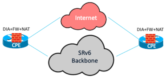
Having DIA offers several operational advantages that enhance network efficiency and management. It improves the internet experience by eliminating the latency caused by backhauling traffic to a central site, thereby boosting application performance and cryptographic throughput by reducing the load on IPsec-encrypted WAN links. It enables you to apply local security policies for firewalls directly at the site or branch. Local breakout also facilitates segmentation to securely separate corporate application traffic from cloud application traffic.
Additionally, extending the SRv6 overlay to the CPE increases agility by continuously monitoring link health and network state for better, dynamic path selection without manual intervention in the overlay for inter-site traffic.
From a business perspective, local breakout to the internet reduces bandwidth consumption at the central site, lowering WAN costs. It improves application performance, minimizing the productivity and revenue loss caused by transport degradation or outages. Furthermore, local breakout contributes to energy efficiency and sustainability benefits in data center environments. OpEx savings are achieved by consolidating SRv6 routing functions and firewall functions on the same CPE router.
Types of traffic
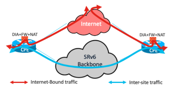
There are two types of traffic, based on source and destination:
● Inter-site traffic: Private, east-to-west traffic (data center or branch to branch) that bypasses inspection to maintain low latency.
● Internet-bound traffic: Traffic destined for unknown or public prefixes that is subject to NAT and Zone-Based Firewall (ZBFW) inspection at the edge.
The Cisco 8000 Series Secure Routers run Cisco IOS XE, which has embedded ZBFW capabilities. More advanced capabilities—such as an Intrusion Detection System (IDS), an Intrusion Prevention System (IPS), Advanced Malware Protection (AMP), and URL filtering—can also be realized through Next-Generation Firewall (NGFW) capabilities. Network security is always implemented with the defense-in-depth principle in mind. You have the option of a distributed ZBFW at the branch routers and another at the internet gateway to form a dual layer of firewall inspection. The embedded firewall consolidates operating costs while providing this dual layer of security.
The configurations in this document reflect ZBFW capabilities. A ZBFW uses zones (groups of interfaces) to define security boundaries. Policies control traffic between zones, allowing or blocking specific types of communication. Deep packet inspection examines packet contents beyond the headers to detect and prevent threats and vulnerabilities, and it tracks the state of active connections, allowing only legitimate, stateful traffic and blocking unauthorized access.
The VRF-Aware Service Infrastructure (VASI) interface is used to apply services with SRv6. It is a logical construct within Cisco IOS XE that functions like a virtual router with an interface pair, in which each interface forwards traffic to the other. This infrastructure is designed to enable services—such as Access Control Lists (ACLs), NAT, policing, and zone-based firewalls—to be applied to traffic flowing between two Virtual Routing and Forwarding (VRF) instances.
Sample network

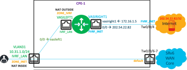
CPE-1 and CPE-2 are two routers at the branch. A Layer 3 VPN exists on these routers, extending the SRv6 overlay to the branch routers. The endpoint—IP address 10.31.1.1/32—is in VLAN 31, connected to CPE-1 in the VRF IVRF_LAN. The WAN-facing interfaces (Two0/0/6 and Two0/0/7) are in the Global Routing Table (GRT). The remote endpoint is 10.41.1.1/32 in VLAN 41, in the VRF IVRF_LAN on CPE-2. FVRF_INET is the forward-facing VRF that contains Two0/0/4, which connects to the Internet Service Provider (ISP). IP address 202.54.22.82/32, reachable through Two0/0/4, simulates a host on the internet.

The VASI pair of interfaces consists of vasileft1 and vasiright1. Interface vasileft1 is in IVRF_LAN, while interface vasiright1 is in FVRF_INET
Configurations
In this document, the configuration starts with the NAT configuration. In this example, a single IP address provides NAT and Port Address Translation (PAT) services to all endpoints on the LAN side behind the router. An access list provides the conditions to apply NAT only to internet-bound traffic and to exclude inter-site traffic. Refer to this configuration:
ip access-list extended 103 deny ip 10.31.1.0 0.0.0.255 10.41.1.0 0.0.0.255
ip access-list extended 103 permit ip 10.31.1.0 0.0.0.255 any
ip nat pool natpool 172.16.1.5 172.16.1.5 prefix-length 24
ip nat inside source list 103 pool natpool vrf IVRF_LAN overload
This is the sequence of configuration steps for the Zone-Based Firewall (ZBFW):
1. Create class maps to classify the traffic of interest.
2. Associate each class map with a policy map, specifying the actions to take on the traffic.
3. Create the zones.
4. Create zone pairs with the source and destination zones.
5. Apply the policy map to the zone pair.
6. Associate the interfaces that form the source and destination with their respective zones.
Create a class map that selects traffic that uses protocols such as HTTP, DNS, and ICMP. Create a policy map to configure inspection as the action for the traffic matched by this class map. Also specify the action to drop and log all other traffic by using the class-default class map.
class-map type inspect match-any LAN-INET
match protocol http
match protocol dns
match protocol icmp
!
policy-map type inspect P-LAN-INET
class type inspect LAN-INET
inspect
class class-default
drop log
Create another policy map, pass, that bypasses inspection for all traffic:
policy-map type inspect pass
class class-default
pass
Create the security zones, and then associate the source and destination zones in a security zone pair.
Note: When you specify inspection as the action, the ZBFW automatically allows return traffic.
zone security ZONE_IVRF
zone security ZONE_INET
zone-pair security IVRF_INET source ZONE_IVRF destination ZONE_INET
service-policy type inspect P-LAN-INET
You also need to create a configuration that allows inter-site traffic to be bypassed without inspection and allowed between the LAN and remote sites. Create a rule for the traffic from the source zone to the destination zone to bypass inspection. Create an additional rule to allow the return traffic that bypassed inspection.
A default zone named default exists for all interfaces that do not have an explicit zone association, but it must be configured explicitly. Following a sequence similar to the previous one:
zone security default
zone-pair security NoFW source ZONE_IVRF destination default
service-policy type inspect pass
zone-pair security NoFW-Return source default destination ZONE_IVRF
service-policy type inspect pass
Next, associate the interfaces with both the NAT and ZBFW configurations completed previously.
interface Vlan31
vrf forwarding IVRF_LAN
ip address 10.31.1.254 255.255.255.0
ip nat inside
zone-member security ZONE_IVRF
!
interface vasileft1
vrf forwarding IVRF_LAN
ip address 169.254.1.1 255.255.255.0
ip nat outside
zone-member security ZONE_INET
!
interface TwoGigabitEthernet0/0/4
description Link to ISP
no switchport
vrf forwarding FVRF_INET
ip address 202.54.22.81 255.255.255.252
!
interface vasiright1
vrf forwarding FVRF_INET
ip address 169.254.1.2 255.255.255.0
Configure the appropriate routing to ensure that inter-site (east-to-west) traffic bypasses the firewall and is forwarded through SRv6, and that only internet-bound traffic is subject to the ZBFW and NAT rules and is forwarded through the interface connected to the ISP.
A static default route in the VRF IVRF_LAN ensures that traffic to unknown prefixes (internet-bound traffic) is forwarded to vasileft1 for firewall inspection and NAT.
Configure a default route, either statically or dynamically, in the internet-facing VRF FVRF_INET. Importantly, you must also advertise the translated source address to the internet to forward traffic destined for that address back to CPE-1.
ip route vrf FVRF_INET 0.0.0.0 0.0.0.0 202.54.22.82
ip route vrf FVRF_INET 172.16.1.5 255.255.255.255 vasiright1
ip route vrf IVRF_LAN 0.0.0.0 0.0.0.0 vasileft1
ip prefix-list NAT seq 5 permit 172.16.1.5/32
route-map v2-nat-filter permit 10
match ip address prefix-list NAT
!
router bgp 1
address-family ipv4 vrf FVRF_INET
redistribute static metric 10 route-map v2-nat-filter
exit-address-family
This output shows the successful NAT operation:
Router# show ip nat translations
Pro Inside global Inside local Outside local Outside global
--- 172.16.1.5 10.31.1.1 --- ---
icmp 172.16.1.5:0 10.31.1.1:0 10.5.1.1:0 10.5.1.1:0
Total number of translations: 2
This output shows that ICMP traffic is inspected from 10.31.1.1/32 to 202.54.22.82/32 and that a session state entry is created by the firewall:
Router# show policy-map type inspect zone-pair sessions
Zone-pair: IVRF_INET
Service-policy inspect : P-LAN-INET
Class-map: LAN-INET (match-any)
Inspect
Established Sessions
Session ID 0x0000002C (10.31.1.1:8)=>(202.54.22.82:0) icmp SIS_OPEN
Created 13:21:13, Last heard 00
Bytes sent (initiator:responder) [973512:973512]
Class-map: class-default (match-any)
Match: any
Drop
0 packets, 0 bytes
This output shows the counters for the inter-site traffic that was bypassed, in continuation of the previous output:
Zone-pair: NoFW
Service-policy inspect : pass
Class-map: class-default (match-any)
Match: any
Pass
1576592 packets, 135586912 bytes
Zone-pair: NoFW-Return
Service-policy inspect : pass
Class-map: class-default (match-any)
Match: any
Pass
1531236 packets, 91874160 bytes
Summary
The integration of distributed network services within an SRv6-enabled fabric offers a robust, scalable solution for modern enterprise and Critical National Infrastructure (CNI) environments. By using the capabilities of Cisco 8000 Series Secure Routers running Cisco IOS XE, organizations can deploy a hybrid architecture that effectively balances the management simplicity of Direct Internet Access (distributed connectivity) with the performance and resiliency of edge-based service enforcement.
Key strategic outcomes of this deployment include:
● Network optimization: Implementing DIA eliminates the latency associated with backhauling traffic to central sites. Extending SRv6 to the CPE enables dynamic path selection and continuous monitoring of link health, ensuring superior application performance.
● Integrated security: The solution uses the embedded Zone-Based Firewall (ZBFW) and NAT capabilities within the Cisco 8000 Series routers. This supports a defense-in-depth strategy, allowing for secure traffic segmentation between sensitive inter-site traffic and public internet-bound traffic.
● Operational agility: By consolidating routing, firewall, and NAT functions onto a single platform, organizations can simplify network operations and reduce the complexity of managing disparate security appliances at the branch level.
● Financial value:
◦ CapEx savings: Eliminates the need for additional hardware by using the robust, multiservice capabilities of existing Cisco 8000 Series Secure Routers.
◦ OpEx savings: Reduces WAN costs by offloading internet traffic from central data centers and lowers operational overhead through function consolidation and automated network management.