Central Internet Gateway with Distributed Network Service in Critical National Infrastructure
Available Languages
Bias-Free Language
The documentation set for this product strives to use bias-free language. For the purposes of this documentation set, bias-free is defined as language that does not imply discrimination based on age, disability, gender, racial identity, ethnic identity, sexual orientation, socioeconomic status, and intersectionality. Exceptions may be present in the documentation due to language that is hardcoded in the user interfaces of the product software, language used based on RFP documentation, or language that is used by a referenced third-party product. Learn more about how Cisco is using Inclusive Language.

Modern Critical National Infrastructure (CNI) is rapidly transforming its digital operations. Industrial sensors now generate an exponential surge in telemetry data. This data flows to cloud-hosted analytics platforms.
To support these mission-critical workloads, network architects must balance two priorities:
● the high-availability benefits of centralized internet gateways, and
● the performance and security advantages of distributed service enforcement.
Centralized internet gateways streamline management and enforce consistent policies. However, relying solely on them can create bandwidth bottlenecks and single points of failure. By adopting a distributed service model, organizations combine the strengths of both approaches:
● Centralized efficiency: Maintains a single point of exit that optimizes internet traffic management and simplifies high-availability orchestration.
● Distributed intelligence: Offloads Network Address Translation (NAT) and firewall processing to the branch edge. This approach reduces the effect of device failures, scales the network horizontally as it grows, and applies security policies as close to the data source as possible.
This white paper details a hybrid architecture that uses Cisco 8000 Series Secure Routers and Segment Routing over IPv6 (SRv6). The architecture demonstrates how organizations can maintain centralized control while distributing NAT and Zone-Based Firewall (ZBFW) inspection to the branch edge. This approach:
● minimizes latency
● optimizes WAN bandwidth, and
● delivers the resiliency that CNI environments require.
Types of traffic
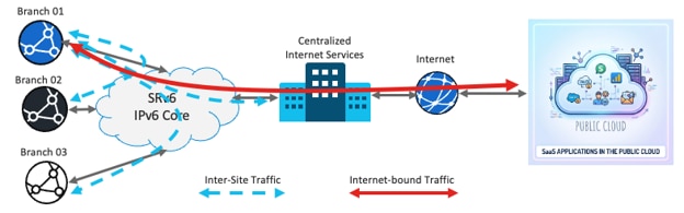
Two types of traffic exist, classified by their sources and destinations.
● Inter-site traffic: Private, east-to-west traffic, such as data center to branch or branch to branch. This traffic bypasses inspection to maintain low latency.
● Internet-bound traffic: Traffic destined for unknown or public prefixes. The router applies Network Address Translation (NAT) and Zone-Based Firewall (ZBFW) inspection to this traffic at the edge.
Firewall capabilities of the Cisco 8000 Series Secure Routers
The Cisco 8000 Series Secure Routers run Cisco IOS XE, which provides embedded Zone-Based Firewall (ZBFW) capabilities. In Autonomous Cisco IOS XE mode, the routers can also provide more advanced Next-Generation Firewall (NGFW) capabilities, including an Intrusion Detection System and Intrusion Prevention System (IDS/IPS).
Network security follows the defense-in-depth principle. To form a dual layer of firewall inspection, you can deploy a distributed embedded firewall at the branch routers and a dedicated, high-performance central firewall appliance at the centralized internet gateway. The embedded firewall on the branch router provides this dual layer of security and reduces operating expenses (OpEx).
How ZBFW works
The configurations in this document use ZBFW capabilities. ZBFW uses zones, which are groups of interfaces, to define security boundaries. Policies control traffic between zones to allow or block specific types of communication.
Deep packet inspection inspects packet contents beyond the headers to detect and prevent threats and vulnerabilities. It also tracks the state of active connections. This stateful inspection allows only legitimate traffic and blocks unauthorized access.
VRF-Aware Service Infrastructure
The VRF-Aware Service Infrastructure (VASI) applies services with Segment Routing over IPv6 (SRv6). VASI is a logical construct within Cisco IOS XE that functions like a virtual router with an interface pair that reflects traffic off each other.
VASI enables you to apply these services to traffic that flows between two different Virtual Routing and Forwarding (VRF) instances:
● access control lists (ACLs)
● Network Address Translation (NAT)
● policing, and
● zone-based firewalls.
Structure of this paper
This paper is organized into these sections:
● Network: Explains the network configurations that you must complete before you implement any network services.
● Distributed NAT : Outlines the configuration that a distributed NAT solution requires.
● ZBFW: Details the configuration that achieves stateful firewall inspection. This inspection applies only to traffic between local sources and internet destinations, and it bypasses east-to-west (inter-site) traffic.
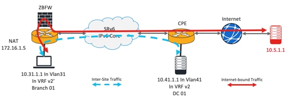
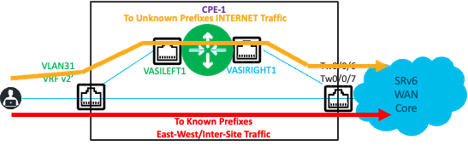
Topology overview
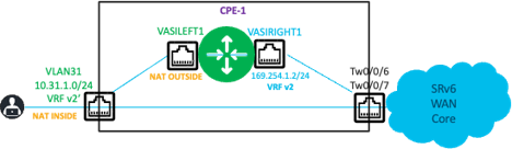
The router on the left is a customer premises equipment (CPE) device in a customer branch. The endpoint, which has the IP address 10.31.1.1, is in VLAN31. This endpoint connects to the router in VRF v2'.
Treat VRF v2' as a shadow VRF of the actual VRF v2. VRF v2 has a BGP VPNv4 session with the remote router. The WAN-facing interfaces are in the global routing table (GRT).
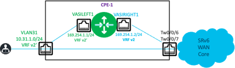
The VRF-Aware Service Infrastructure (VASI) interface pair consists of vasileft1 and vasiright1.
● Interface vasileft1 is in VRF v2'.
● Interface vasiright1 is in VRF v2.
The remote router simulates a local LAN connected to it. The internet is reachable through another router in the LAN.
● A server with the IP address 10.41.1.1 simulates the remote LAN. This server connects to VLAN41 in VRF v2.
● The internet route is reachable through 10.41.1.250.
VRF and VASI interface definitions
This configuration defines the VRFs and the VASI left and right interface pair:
vrf definition v2
rd 1:2
!
address-family ipv4
route-target export 1:2
route-target import 1:2
exit-address-family
vrf definition v2'
rd 1:7
!
address-family ipv4
route-target export 1:7
route-target import 1:7
exit-address-family
Route leaking requirements
The subnet addresses of the VASI interfaces are locally significant, so the router does not advertise them externally. To establish reachability between the local and remote sites, you must leak prefixes in both directions:
● Leak the subnet prefixes in VRF v2' into VRF v2 and advertise these leaked prefixes through BGP to the remote router. This advertisement provides reachability to the local site.
● Leak the known remote prefixes in VRF v2 into VRF v2'. This leaking provides VRF v2' with the path to the remote site through the Segment Routing over IPv6 (SRv6) path.
In this example, this is how route leaking works:
● The router leaks the local prefix 10.31.1.0/24 from VRF v2' to VRF v2 and advertises it through BGP VPNv4 to the remote CPEs.
● The remote CPE advertises 10.41.1.0/24 and the default route in VRF v2. The router leaks only 10.41.1.0/24 from VRF v2 into VRF v2'.
Procedure 1. Configuring reachability within the VRFs:
Complete these steps to achieve reachability from within the VRFs.
Step 1. Create an IP prefix list that permits the local prefixes.
ip prefix-list LOCAL_PREFIXES seq 5 permit 10.31.1.0/24
Step 2. Create an IP prefix list that denies the local prefixes.
ip prefix-list DENY_LOCAL_PREFIXES seq 5 deny 10.31.1.0/24
Step 3. Create a route map that allows only the local prefixes.
route-map REDIS_LOCAL_PREFIXES permit 10
match ip address prefix-list LOCAL_PREFIXES
Step 4. Create a route map that prevents the local prefixes but allows others.
route-map REDIS_REMOTE_PREFIXES permit 10
match ip address prefix-list DENY_LOCAL_PREFIXES
route-map REDIS_REMOTE_PREFIXES permit 20
Step 5. Leak the prefixes from VRF v2' to VRF v2 with the route maps. In this example, the router leaks only 10.31.1.0/24.
vrf definition v2
rd 1:2
address-family ipv4
route-replicate from vrf v2' unicast connected route-map REDIS_LOCAL_PREFIXES
Step 6. Leak the prefixes from VRF v2 to VRF v2' with the route maps. In this example, the router leaks only 10.41.1.0/24.
vrf definition v2'
rd 1:7
address-family ipv4
route-replicate from vrf v2 unicast bgp 1 route-map REDIS_REMOTE_PREFIXES
Verifying the route leaking
The BGP table of each VRF reflects the result of the configuration.
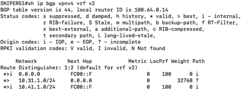
The VRF v2 BGP table contains the local prefix 10.31.1.0/24 from VRF v2'. The remote router advertises the 0/0 and 10.41.1.0/24 prefixes. The router learns these prefixes over SRv6 with the next hop set to FC00::F.
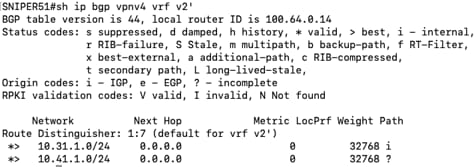
The VRF v2' BGP table contains the remote prefix 10.41.1.0/24 from VRF v2.
Advertising leaked prefixes to remote peers
The router does not automatically advertise locally leaked prefixes to remote BGP peers. Do this additional procedure:
Procedure 2. To advertise the locally leaked prefixes to the remote peers:
router bgp 1
address-family ipv4 vrf v2
redistribute vrf v2' connected route-map REDIS_LOCAL_PREFIXES
exit-address-family
Procedure 3. (Optional) Do this only if there are BGP peers in VRF v2' that require the router to advertise the remote prefix further:
address-family ipv4 vrf v2'
network 10.31.1.0 mask 255.255.255.0
redistribute vrf v2 bgp 1 route-map REDIS_REMOTE_PREFIXES
Forwarding behavior
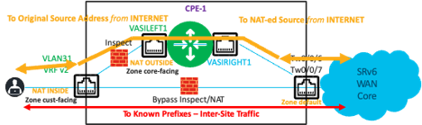
The preceding configuration ensures that the router forwards inter-site (east-to-west) traffic through the normal forwarding path. This traffic, which travels from the LAN side of the left router (VRF v2') to known prefixes, is encapsulated in SRv6 and forwarded toward the WAN core. This traffic bypasses the VASI interface infrastructure.
The router uses the VASI infrastructure only to forward traffic to unknown destinations, which are typically on the internet. A default static route that points to the interface vasileft1 ensures that the router forwards only internet-bound traffic through the VASI infrastructure.
ip route vrf v2' 0.0.0.0 0.0.0.0 vasileft1
NAT and Port Address Translation (NAT/PAT) support a distributed NAT44 solution in the network. You can deploy NAT/PAT at each branch to gain these benefits:
● reduces dependency on one or two central resources
● reduces the effect of any failures at the central locations
● provides horizontal scaling for this service throughout the network, and
● ensures efficient usage of the NAT inside global addresses.
This example uses one IP address to provide NAT/PAT services to all endpoints on the LAN side behind the router. An access list defines the conditions that determine which traffic the router translates.
ip nat pool natpool 172.16.1.5 172.16.1.5 prefix-length 24
ip nat inside source list 103 pool natpool vrf v2' overload
ip access-list extended 103 deny ip 10.31.1.0 0.0.0.255 10.41.1.0 0.0.0.255
ip access-list extended 103 permit ip 10.31.1.0 0.0.0.255 any
Configuring the NAT inside and outside interfaces
The LAN interface VLAN31 is the inside interface, and vasileft1 is the outside interface for NAT.
interface Vlan31
vrf forwarding v2'
ip nat inside
!
interface vasileft1
vrf forwarding v2'
ip nat outside
Outbound traffic flow
The router forwards traffic from 10.31.1.X to an unknown destination, such as 10.5.1.1/32 in this example, to vasileft1 through the static default route. Because this traffic matches the access list, the router applies NAT translation. The VASI pair reflects this translation in VRF v2. The remote peer advertises the default route in VRF v2, so the router forwards the traffic through Segment Routing over IPv6 (SRv6) to the remote peer.
Return traffic flow
For the return traffic, the translated NAT address, which is 172.16.1.5 in this example, is the destination address. To enable the remote peer to forward the return traffic to the correct peer, you must advertise 172.16.1.5/32 to the remote peer in VRF v2.
The local peer (CPE-1, or the left router) requires a route in VRF v2 to forward the return traffic. This route forwards traffic from internet destinations to the translated NAT address (172.16.1.5/32) and on to the vasiright1 interface for NAT processing.

ip route vrf v2 172.16.1.5 255.255.255.255 vasiright1
!
router bgp 1
address-family ipv4 vrf v2
redistribute static metric 10
Optionally, you can attach a route map to the preceding redistribute static command for controlled redistribution.
Verifying the NAT operation
This output shows the successful NAT operation.
SNIPER51#show ip nat translations
Pro Inside global Inside local Outside local Outside global
--- 172.16.1.5 10.31.1.1 --- ---
icmp 172.16.1.5:0 10.31.1.1:0 10.5.1.1:0 10.5.1.1:0
Total number of translations: 2
ZBFW service
Configuring ZBFW inspection for internet-bound traffic
In this example, the configuration first creates a policy that redirects specific traffic for inspection. It then creates a policy that bypasses inspection for inter-site traffic.
Procedure 4. Configuring ZBFW inspection for internet-bound traffic:
Step 1. Create a class map that selects the traffic that uses the HTTP, DNS, and ICMP protocols.
class-map type inspect match-any LAN-INET
match protocol http
match protocol dns
match protocol icmp
Step 2. Create a policy map that inspects the traffic matched by the class map. Use the class-default class map to drop and log all other traffic.
policy-map type inspect P-LAN-INET
class type inspect LAN-INET
inspect
class class-default
drop log
Step 3. Create another policy map that passes all traffic and bypasses inspection. This policy map bypasses inspection for inter-site traffic.
policy-map type inspect pass
class class-default
pass
Step 4. Create two security zones: one for the LAN-facing side of the network, and one for the WAN-facing side. Create a zone pair that specifies the source zone and the destination zone, and apply the appropriate policy map to the zone pair.
zone security cust-facing
zone security core-facing
zone-pair security cust-inet source cust-facing destination core-facing
service-policy type inspect P-LAN-INET
This configuration inspects the traffic that uses the HTTP, DNS, and ICMP protocols, sourced from the cust-facing zone (LAN side) and destined for the core-facing zone (WAN side). The configuration drops all other traffic.
Step 5. Configure VLAN31 as a member of the cust-facing zone and configure the VASI interface vasileft1 as a member of the core-facing zone. This step associates the interfaces with the zones that you created.

Summary of the ZBFW configuration steps
Procedure 5. To configure ZBFW inspection:
Step 1. Create class maps to classify the traffic.
Step 2. Associate each class map with a policy map that specifies the actions to take on the traffic.
Step 3. Create the security zones.
Step 4. Create the zone pairs with the source and destination zones.
Step 5. Apply the policy map to the zone pair.
Step 6. Associate the source and destination interfaces with their respective zones.
Note: You do not need to create a return policy map for inspected traffic. The inspection creates implicit rules that allow return traffic back to the sources.
Bypassing inspection for inter-site traffic
You must also create a configuration that allows inter-site traffic to bypass inspection and pass between the LAN and remote sites. This configuration requires two rules:
● a rule that allows traffic from the source zone to the destination zone to bypass inspection, and
● a rule that allows the return traffic that bypassed inspection.
A default zone, named default, exists for all interfaces that do not have an explicit zone association. You must configure this zone explicitly. This configuration follows a sequence similar to the preceding steps.
zone security default
zone-pair security NoFW-1 source cust-facing destination default
service-policy type inspect pass
zone-pair security NoFW-Return-1 source default destination cust-facing
service-policy type inspect pass
Traffic flows
These sections summarize the traffic flows to and from the local branch, remote sites, and the internet. The configuration selectively applies network security functions to internet-bound traffic.
Traffic from VLAN31 to the internet
Traffic from VLAN31 to unknown prefixes (the internet) follows the static default route to vasileft1. The ZBFW inspects this traffic. If the firewall allows the traffic, the router applies source NAT to translate the address from 10.31.1.1/32 to 172.16.1.5/32. The router forwards the traffic to vasileft1, which reflects it to vasiright1. The router looks up the destination in VRF v2, follows the default route to the remote site, encapsulates the traffic within Segment Routing over IPv6 (SRv6), and forwards it out the WAN interface.
Return traffic from the internet to VLAN31
Return traffic from the internet to VLAN31 (the NAT address 172.16.1.5/32) follows the BGP VPNv4 route in VRF v2 on the remote router. The remote router encapsulates this traffic in SRv6 and forwards it to the appropriate peer. The local router (CPE-1) receives the traffic and decapsulates the SRv6 header. The router looks up the destination in VRF v2 and follows the static route to vasiright1, which reflects the traffic to vasileft1 in VRF v2'. The router uses the NAT table entry to translate the destination address 172.16.1.5/32 back to the original IP address 10.31.1.1/32. The router references the inspection table to find a session state entry and, if the firewall allows the traffic, forwards it to VLAN31.
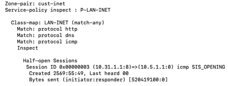
An output snippet from the show policy-map type inspect zone-pair sessions command shows the session state entry that ZBFW creates for the flow from 10.31.1.1/32 to 10.5.1.1/32 (an unknown prefix).
Inter-site traffic
The router forwards traffic between VLAN31 and other known remote site prefixes in both directions without NAT or ZBFW inspection. This traffic follows the usual lookup sequence and is encapsulated with SRv6. The output of the same command verifies this behavior, because it shows no session states for inter-site traffic.

Summary: architecting for scale and resilience
The integration of distributed network services within a fabric that uses Segment Routing over IPv6 (SRv6) provides a scalable solution for modern enterprise and Critical National Infrastructure (CNI) environments. The Cisco 8000 Series Secure Routers run Cisco IOS XE. By using the capabilities of these routers, organizations can deploy a hybrid architecture. This architecture balances the management simplicity of a centralized internet gateway with the performance and resiliency of edge-based service enforcement.
This deployment provides these key strategic outcomes:
● Enhanced operational resilience: Distributes Network Address Translation (NAT) and Zone-Based Firewall (ZBFW) services to the branch edge. This distribution minimizes the effect of localized failures and eliminates single points of dependency on central resources.
● Horizontal scalability: Scales services linearly as the number of branches grows. This distributed model maintains consistent performance as the network expands and prevents the bottlenecks that centralized-only service architectures often cause.
● Defense-in-depth security: Applies dual-layer security by inspecting traffic at both the branch edge and the centralized gateway. This approach provides a comprehensive, multi-layered security posture that protects against evolving threats.
● Core network optimization: Moves SRv6 encapsulation and service application to the customer premises equipment (CPE). This change simplifies the core infrastructure, reduces core complexity, lowers overhead, and increases overall network throughput.
This architecture provides a foundation for high-performance networks. It helps keep critical data flows, from industrial sensors to cloud-based applications, secure, reliable, and performant.