Extended Fast Software Upgrade (xFSU) on
Cisco Catalyst 9300 Series Switches White Paper
Available Languages
Bias-Free Language
The documentation set for this product strives to use bias-free language. For the purposes of this documentation set, bias-free is defined as language that does not imply discrimination based on age, disability, gender, racial identity, ethnic identity, sexual orientation, socioeconomic status, and intersectionality. Exceptions may be present in the documentation due to language that is hardcoded in the user interfaces of the product software, language used based on RFP documentation, or language that is used by a referenced third-party product. Learn more about how Cisco is using Inclusive Language.
The high cost of downtime in modern enterprise networks
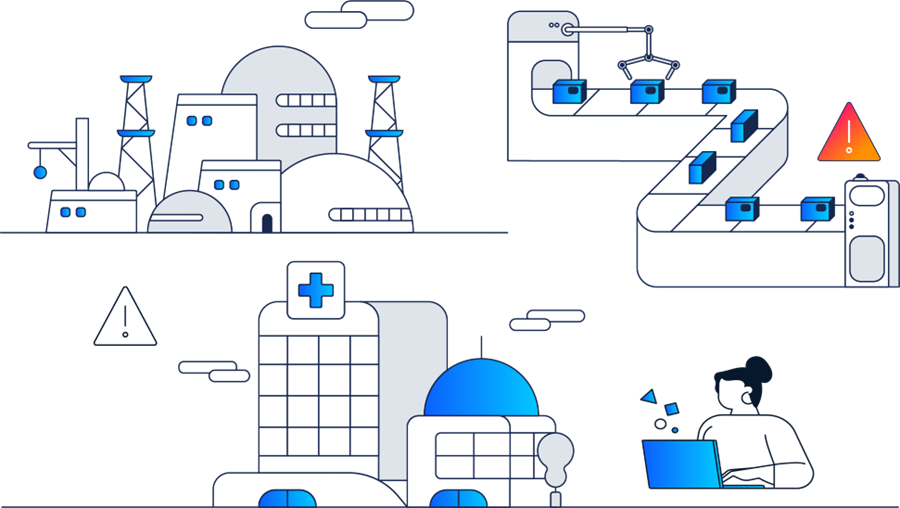
Keeping modern enterprise networks running smoothly requires balancing two opposing forces: the need to remain always available and the need to continuously upgrade software to address bugs, security vulnerabilities, and new feature requirements. In mission-critical environments such as hospitals, airports, financial institutions, and manufacturing floors, maintenance windows are shrinking while expectations for stability continue to rise.
Traditional upgrades on campus switches require taking devices offline for several minutes. This disrupts users, resets wireless sessions, interrupts voice and video traffic, and can power-cycle Power over Ethernet (PoE) endpoints. In networks with tight convergence timers, even brief outages can trigger routing reconvergence or spanning-tree events, amplifying the impact. As a result, many organizations delay upgrades, accumulating technical debt, unresolved defects, and unpatched security exposures.
The challenge is especially acute in the access layers. These switches sit directly in the path of users, IoT devices, sensors, and building systems—and many are single-homed with no alternate path during maintenance. Taking them offline instantly disconnects every endpoint downstream. In large environments, upgrading dozens or hundreds of such switches creates a substantial operational burden, often forcing teams to schedule overnight or weekend maintenance to avoid widespread service impact.
Upgrades present challenges in mission-critical environments
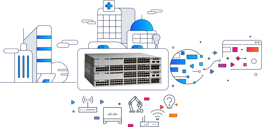
High availability in the Catalyst 9000 family: The architectural response to downtime
The Cisco Catalyst™ 9000 family addresses these challenges through a high availability (HA) architecture designed to maintain continuous system availability during failures and planned maintenance events, leveraging platform-level redundancy and resiliency mechanisms.
However, in access-layer deployments, where switches may be standalone and directly serve single-homed endpoints, software upgrades can still result in traffic disruption. Even when campus-wide HA and lifecycle-management solutions such as In-Service Software Upgrade (ISSU) are used in the core and distribution layers, the access layer remains uniquely sensitive to downtime due to limited or absent redundancy during maintenance.
This white paper focuses on Extended Fast Software Upgrade (xFSU) for the Catalyst 9300 Series switches—a capability that builds on the Catalyst 9000 HA foundation to enable software upgrades and reloads with minimal traffic disruption in environments where downtime has traditionally been unavoidable.
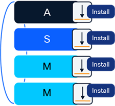
Catalyst 9300 enables xFSU for minimal-disruption switch upgrades with endpoint continuity
Extended Fast Software Upgrade: Solving the challenges of traditional upgrades
Introduction
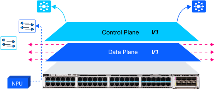
xFSU builds on the Catalyst 9000 HA foundation by separating the control plane from the data plane during software transitions. Instead of performing a full system reboot that clears application-specific integrated circuit (ASIC) tables, interrupts PoE, and forces routing and spanning-tree reconvergence, xFSU upgrades the control plane processes first while the data plane continues forwarding traffic using forwarding entries already programmed in hardware. Clients remain connected and forwarding continues without triggering disruptive topology events. Once the new control plane is fully operational, the system upgrades the data plane, reducing total traffic downtime to seconds-level1 disruption.
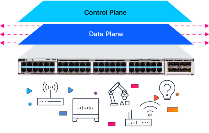
Separation of control plane and data plane during xFSU operation
By eliminating a power cycle and preserving the hardware forwarding state through the upgrade, xFSU turns software maintenance into a predictable and near-hitless operation. It works seamlessly across standalone and stacked switches and supports both Layer 2 and Layer 3 access designs without requiring changes to the existing network topology. This makes xFSU a scalable solution for environments where access switches are often single-homed and continuous service is essential.
Note: xFSU can be used to perform both software upgrades and reloads (reload fast).
Key concepts enabling xFSU
xFSU builds on resiliency mechanisms already present in modern network architectures. Two of the most important concepts, Graceful Restart and Non-Stop Forwarding, allow forwarding to continue and routing adjacencies to remain stable even when control plane processes restart.
Control plane and data plane separation
A strict separation is maintained between the control plane, which handles routing decisions, and the data plane, which delivers hardware-accelerated packet forwarding.
● Control plane (RIB)
The Routing Information Base (RIB) resides in the control plane and maintains routing information learned from routing protocols such as Open Shortest Path First (OSPF), Border Gateway Protocol (BGP), and intermediate system-to-intermediate system (IS-IS). Routing protocols compute routes and install their selected routes into the RIB. The RIB maintains the active routing table in software on the CPU and serves as the source for programming the forwarding plane.
● Data plane (FIB)
The Forwarding Information Base (FIB) resides in the data plane and enables hardware-accelerated, wire-speed packet forwarding. It is populated from the RIB and programmed into the ASIC’s ternary content-addressable memory (TCAM) and registers, allowing forwarding decisions to occur without CPU involvement. Once programmed, the FIB operates independently of the control plane.
Graceful Restart: Preserving routing adjacencies during an upgrade
Graceful Restart (GR) allows the device to restart its control plane without triggering routing reconvergence. Instead of treating the restart as a failure, neighbors are made aware of the graceful reload. Neighbors maintain all route information shared by the reloading node, without any keep-alive traffic. This ensures uninterrupted Layer 3 stability during the upgrade.
When a Graceful Restart is initiated, the switch performs a coordinated sequence of operations:
1. Pre-restart notification:
The control plane signals all routing neighbors that a controlled restart is in progress, using protocol-specific mechanisms such as OSPF Grace link-state advertisements (LSAs), IS-IS restart signaling, or BGP Graceful Restart capabilities (explained in the “Additional Information” boxes in the “Device Configuration Requirements” section).
2. State checkpoint:
Critical forwarding states, including the FIB, interface configurations, and protocol state, are checkpointed to persistent storage.
3. Control plane restart:
The control plane software restarts while the data plane continues forwarding traffic using the preserved FIB entries.
4. State restoration:
After restart, the control plane restores its state from the checkpoint and resynchronizes with neighbors, who have maintained their adjacencies throughout the process.
Non-Stop Forwarding (NSF)
NSF allows the data plane to continue forwarding packets while the control plane restarts. During this brief recovery window, the ASIC forwards traffic using the FIB already programmed in hardware. As long as the network topology remains stable, traffic flows uninterrupted while the control plane restarts and resynchronizes. This enables a near-hitless operation when used together with Graceful Restart.
Inner workings of xFSU: Step by step
xFSU delivers near-zero downtime by upgrading the control plane and data plane independently and preserving the forwarding state through most of the process.
The workflow consists of five core phases once the upgrade is triggered.
1. Pre-upgrade preparation and neighbor notification
● Handling Layer 3 routing protocols
Before the control plane restarts, all routing neighbors are notified using their protocol-specific Graceful Restart (GR) mechanisms.
● The control plane sends GR notifications to all routing neighbors.
Each protocol uses its own GR mechanism.
BGP: Sends end-of-RIB markers and advertises
GR capability
IS-IS: Sets the restart request (RR) bit in hello protocol data units (PDUs)
OSPF: Floods Grace LSAs to all neighbors (explained in the “OSPF: Additional Information” box in the “Device Configuration Requirements” section)
● Neighbors enter a “helper” or “restart-aware” mode, maintaining adjacency even if control plane hellos are missed.
Graceful Restart (GR) notifications sent to all routing neighbors
Outcome: Routing adjacencies remain intact throughout the control plane restart, eliminating reconvergence events.
● Handling Layer 2 protocols
Unlike routing protocols, Link Aggregation Control Protocol (LACP) is not GR aware and uses aggressive timers. During a control plane restart, these timers would normally cause the peer to bring the port channel down. To prevent this, xFSU offloads LACP keep-alives to hardware.
LACP offload mechanism:
● The micro engine on the neural processing unit (NPU) temporarily takes over LACP PDU generation while Cisco IOS® XE is restarting.
● It sends keep-alives at the configured rate, ensuring that the peer sees an uninterrupted LACP flow.
● Once the control plane is back online, the software resumes ownership, with no state loss.
NPU offloads LACP PDU generation during control plane restart
Outcome: Port channels remain up, with no flaps or renegotiation.
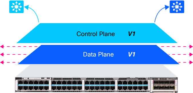
2. Control plane upgrade while forwarding continues
● The control plane processes stop and restart with the new IOS XE version.
● The data plane (ASIC) continues forwarding traffic using the previously programmed FIB and MAC tables.
● Interfaces remain up, PoE stays active, and no spanning-tree or routing reconvergence occurs.
Note: Ensure that Perpetual PoE is enabled on interfaces connected to PoE-powered endpoints.

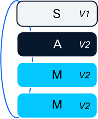
Control plane has been upgraded from V1 to V2
Outcome: Users, wireless clients, voice endpoints, and applications remain connected.
3. Hardware state caching
● Before upgrading the data plane, the switch captures:
◦ FIB entries
◦ MAC address table
◦ Address Resolution Protocol (ARP) table
◦ Access control list entries (ACL TCAM entries)
◦ Quality of service (QoS) and policy configurations
● These entries are stored in memory for rapid restoration after the ASIC reset.
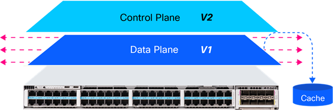
Before data plane upgrades to V2, data plane entries are cached
Outcome: The system can restore full forwarding immediately after the data plane transition.
4. Data plane upgrade (the only downtime window)
● The ASIC is reset and upgraded from version V1 to V2.
● Network interfaces are temporarily disabled.
● All hardware tables (FIB/MAC/ACL/QoS) are flushed.
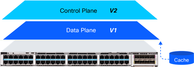
Data plane upgrades with cached forwarding state being flushed
Outcome: A brief seconds-level forwarding pause occurs while the data plane reinitializes.
5. State restoration and full forwarding resume
● The cached ASIC entries are reprogrammed into TCAM and register space.
● Interfaces are reenabled, and all Layer 2/Layer 3 forwarding paths return immediately.
● Control plane neighbors confirm synchronization and exit helper mode.
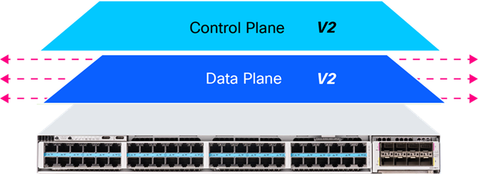
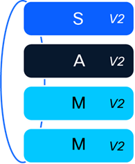
Control and data planes upgraded to V2
Outcome: Traffic resumes with the same forwarding state as before the upgrade, with no reconvergence delay.
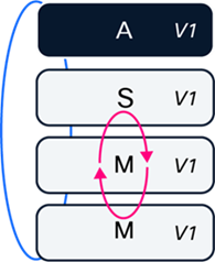
In a Catalyst 9300 stack, xFSU upgrades all members without bringing down the stack as a whole. Instead of reloading the system simultaneously, the upgrade is staggered across members, using Stateful Switchover (SSO) to preserve control plane continuity and maintain uninterrupted forwarding.
Tip: This capability is especially beneficial for protocols and services sensitive to control plane interruption like Simple Network Management Protocol (SNMP) traps, ARP inspection, etc.
1. Software image distribution
The new software image is delivered to all stack members.
All stack members receiving new software image
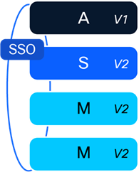
2. Standby and member upgrade
● During this phase, the standby and all nonactive members go through the xFSU process to upgrade to the new software version.
● While this upgrade is in progress, the active switch continues to operate on the existing software version and maintains full Layer 2 and Layer 3 forwarding for the stack.
● Stack ports, uplinks, PoE, and routing adjacencies remain stable during this phase.
Upgrading standby and nonactive members to V2
3. Stateful Switchover (SSO)
● When the standby finishes upgrading, SSO transitions the control plane role from the active member to the newly upgraded standby.
Initiating SSO between active and standby
● The upgraded standby becomes the new active switch and assumes full forwarding and control plane responsibility.
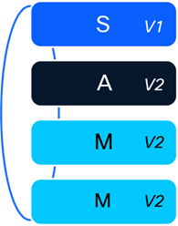
The standby is now the new active switch
4. Final upgrade of the remaining switch
● The last switch (now serving as the standby) performs its upgrade with xFSU.
Upgrade performed on the standby switch
● With an already-upgraded active switch forwarding traffic, the stack continues to operate normally.
● Once this switch returns, the entire stack is now running the new software version.
Entire stack is now upgraded
Note: In stack deployments, the active/standby roles will change as part of the xFSU workflow. If the original role assignment must be restored, it can be reestablished only through a fast reload after the timer expires. The timer ensures that all GR-capable protocols have sufficient time to fully restore their state.
Stack convergence time analysis
With xFSU, each switch in the stack undergoes a controlled upgrade, resulting in seconds-level disruption per switch, a substantial improvement over traditional upgrades in which the entire stack can remain offline for 10 minutes or more.

Seconds-level downtime observed per switch in a stack
The above diagram assumes a four-member Catalyst 9300 stack.
Note: xFSU is designed for environments where access switches are often single homed, so all uplink and downlink interfaces remain up throughout the process. As a result, the stack does not rehash or redistribute traffic across links, even when devices are multihomed or dual-attached, preserving stable forwarding behavior during the upgrade.
Flexible implementation scenarios
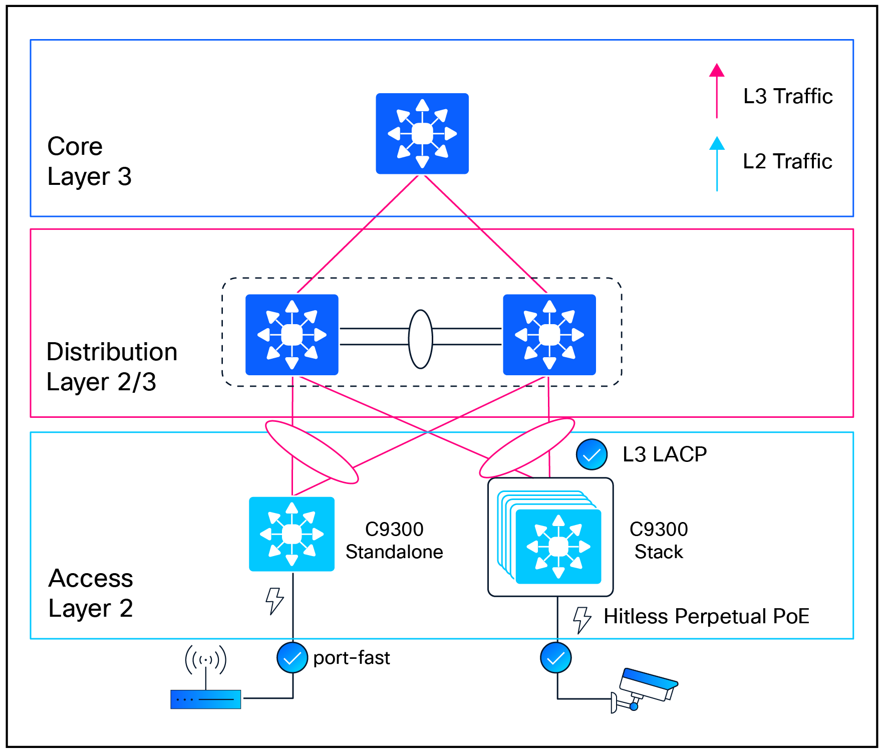
Topology 1: Layer 2 access node (stack or standalone)
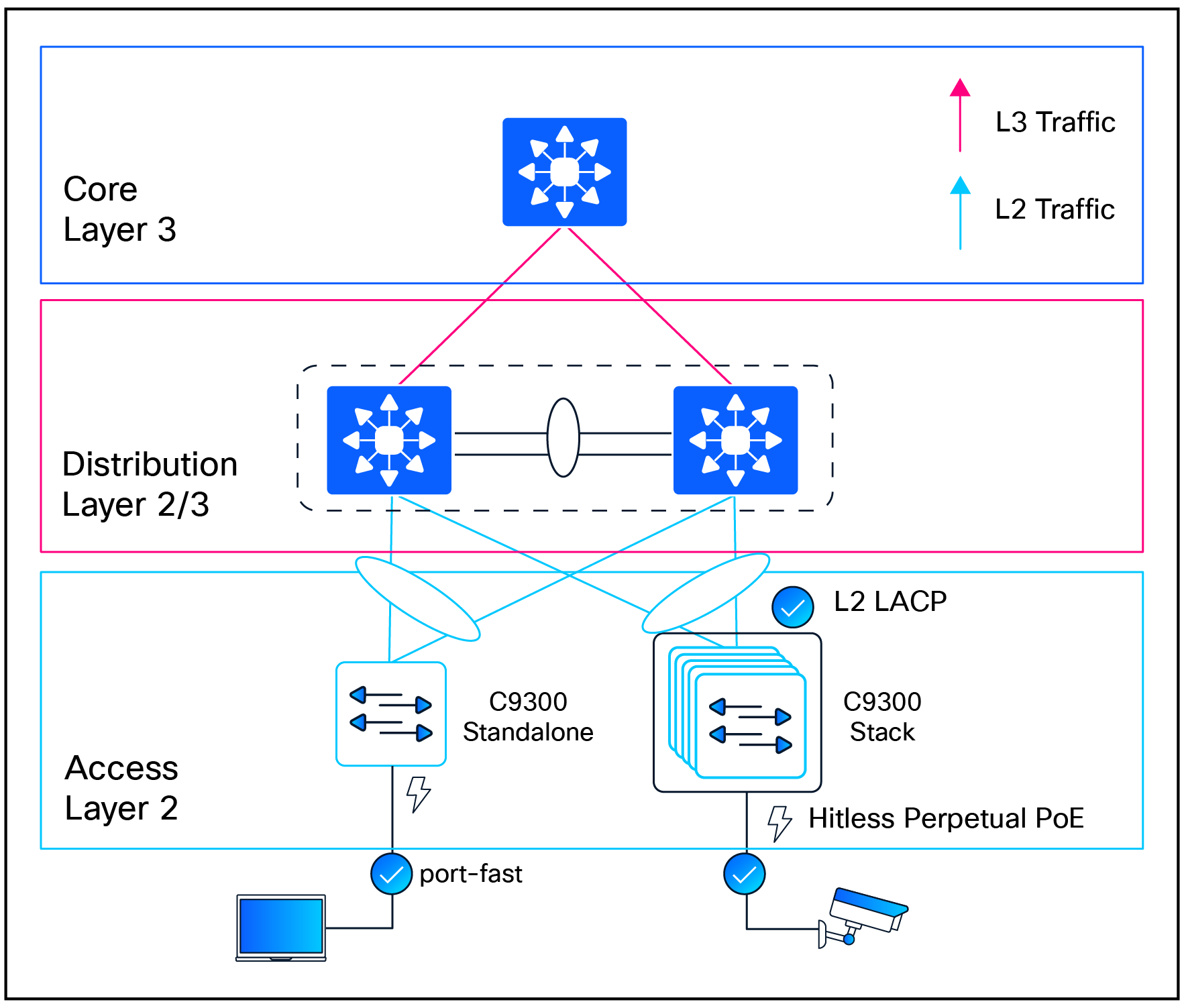
xFSU executed on Layer 2 access nodes
Catalyst 9300 switches acting as pure Layer 2 access nodes fully support xFSU, whether deployed as standalone switches or a multimember stack.
All standard Layer 2 protocols, including Spanning Tree Protocol (STP) (Rapid STP [RSTP], Multiple STP [MSTP]), Per-VLAN Spanning Tree (PVST), Unidirectional Link Detection (UDLD), and EtherChannel (Port Aggregation Protoco, LACP) remain supported without requiring configuration changes.
PortFast helps ensure that host-facing ports stay in the forwarding state, maintaining end-user connectivity throughout the upgrade.
To ensure uninterrupted power delivery during the upgrade, Perpetual PoE must be configured on interfaces connected to PoE-powered endpoints.
Topology 2: Layer 2 extended access node (stack)
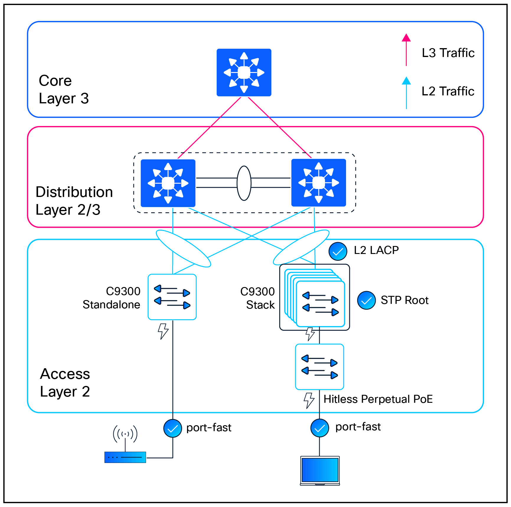
xFSU executed on Layer 2 extended access nodes
With IOS XE Release 17.18.1, Catalyst 9300 stacks fully support operating as the STP root in extended Layer 2 access deployments. This enhancement provides the stability required to run xFSU on the stack without creating STP root conflicts during the control plane upgrade. Because a stack always maintains an active control plane, the STP root role remains intact throughout the xFSU workflow, helping ensure predictable Layer 2 behavior across downstream switches.
PortFast on client-facing interfaces further keeps host ports in the forwarding state, preserving end-user connectivity during the upgrade.
Additional deployment use case: For small branch deployments, a Catalyst 9300X stack operating as the collapsed core switch (often selected for its built-in IPsec capabilities), serving as the STP root for a single downstream access device, can also execute xFSU.
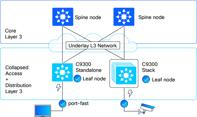
Topology 3: Layer 3 routed access node (stack or standalone)
xFSU executed on Layer 3 routed access nodes
In routed-access designs, Catalyst 9300 switches operating as standalone nodes or as a stack participate in Layer 3 forwarding at the access layer. The topology is fully supported for xFSU with common Layer 3 constructs used in enterprise networks, including routed interfaces, switch virtual interfaces (SVIs) in routed mode, and Layer 3 port channels. xFSU operates seamlessly with all GR–capable routing protocols, such as OSPF, IS-IS, and BGP, allowing routing adjacencies to remain stable during the control plane upgrade.
PortFast continues to be recommended on host-facing access ports to keep client interfaces in the forwarding state and avoid unnecessary delays, ensuring consistent end-user connectivity throughout the upgrade.
Topology 4: Fabric leaf node (stack or standalone)
xFSU executed on Fabric leaf nodes
Catalyst 9300 Series switches deployed as BGP Ethernet VPN (EVPN) leaf nodes in a VXLAN fabric fully support xFSU, whether operating as standalone devices or as a stack, starting with IOS XE Release 26.1.1.
With BGP EVPN’s built-in support for GR, the control plane restarts that occur during xFSU do not interrupt or reset EVPN peering. The forwarding plane continues to use the previously installed VXLAN and MAC/IP routing state, allowing BGP EVPN adjacencies to remain established, VXLAN tunnels to stay active, and endpoint reachability to be maintained throughout the upgrade.
Traffic behavior during xFSU
xFSU delivers seconds-level traffic disruption for Layer 2 and Layer 3 unicast forwarding and Layer 2 multicast traffic.
Layer 3 multicast traffic behavior during xFSU depends on the preservation of a Protocol Independent Multicast (PIM) routing state and timely Internet Group Management Protocol (IGMP) receiver reidentification by hosts.
For a comprehensive list of supported protocols and features, refer to the following technical note:
Understand Extended Fast Software Upgrade on Catalyst 9300 Series Switches.
xFSU eligibility, prechecks, and minimal-impact configuration
Before initiating an xFSU operation, the system performs a comprehensive precheck to verify that both the device and the target image are compatible with xFSU requirements. This helps ensure a safe, predictable, and supported upgrade experience.
Hardware and cabling requirements
● Supported platforms: Catalyst 9300 Series, Catalyst 9300L from IOS XE 17.3.2a, and Catalyst 9300X from IOS XE 17.7.1.
● Stack topology: Stack setups require a full ring topology; partial rings are not supported.
Device configuration requirements
● Auto-boot configuration: Auto-boot must be enabled (the default setting) to ensure that switches reload automatically into IOS XE during the xFSU workflow.
● Install mode: The switch must be operating in install mode, not bundle mode.
● Stack topology: SSO must be operational (the default setting) so the stack maintains a healthy active-standby pair for nondisruptive control plane switchover during xFSU.
● Routing protocol-specific Graceful Restart configurations: If the following routing protocols are configured, the specified GR configuration is necessary on the switch as well as the routing peers.
RECAP: GR mechanisms ensure that neighbors temporarily tolerate the control plane restart by preserving adjacencies and forwarding state for a defined restart window. This window must be sufficiently long to accommodate the brief xFSU control plane restart interval.
BGP
BGP Graceful Restart (RFC 4724) needs to be configured to allow BGP sessions to be preserved across a restart, preventing route withdrawals and the resulting traffic disruption.
Configuration
C9300(config-router)# bgp graceful-restart
C9300(config-router)# bgp graceful-restart restart-time 900
C9300(config-router)# bgp graceful-restart stalepath-time 1800
Note: If not configured, your system will show up as ineligible to execute xFSU.
| BGP: Additional information How it works: ● Capability advertisement: During session establishment, BGP peers exchange Graceful Restart capabilities in their OPEN messages. This indicates their ability to preserve the forwarding state during a restart. ● Restart notification: When the switch initiates xFSU, the BGP process sends end-of-RIB markers and sets the Restart bit in its capability advertisement. ● Route preservation: Neighbors mark all routes learned from the restarting router as "stale" but continue to use them for forwarding. They do NOT withdraw these routes from their own neighbors. ● Session reestablishment: After restart, the BGP process reestablishes sessions with its neighbors and exchanges routes. ● Stale route cleanup: Once the full routing table is exchanged, stale routes that were not refreshed are removed. Key timers: The Restart Time (default 120 seconds) defines how long neighbors wait for the restarting router to reestablish the session, while the Stale Path Time (default 360 seconds) defines how long stale routes are retained. Because xFSU exceeds the default BGP Graceful Restart timers, the Restart Time is set to 900 seconds, and the Stale Path Time is set to 1800 seconds. |
IS-IS
IS-IS Graceful Restart (RFC 5306) needs to be configured to allow IS-IS adjacencies to be maintained during a router restart, preventing SPF recalculation across the network.
Configuration
C9300(config-router)# nsf ietf
or
C9300(config-router)# nsf cisco
Note: If not configured, your system will show up as ineligible to execute xFSU.
| IS-IS: Additional information How it works: ● Restart TLV: The restarting router includes a Restart TLV in its hello PDUs, indicating it is capable of Graceful Restart. ● Restart request: When xFSU begins, IS-IS sends hello PDUs with the Restart Request (RR) bit set, indicating a restart is in progress. ● Neighbor suppression: Neighbors that receive the RR bit suppress their normal reaction to the restart. They do NOT remove the restarting router from their link state packet (LSP) database and do NOT trigger SPF recalculation. ● Adjacency preservation: Neighbors maintain the adjacency in the "UP" state even though hello PDUs may be missed during the restart window. ● Database synchronization: After restart, IS-IS resynchronizes its LSP database with neighbors using normal flooding procedures. Key benefit: By suppressing SPF recalculation, IS-IS Graceful Restart prevents the ripple effect of route changes across the entire IS-IS domain. The network continues to forward traffic along established paths. |
OSPF
OSPF Graceful Restart (RFC 3623 for OSPFv2, RFC 5187 for OSPFv3) enables OSPF routers to maintain their adjacencies and prevent network-wide reconvergence during a restart.
Note: OSPF is by default NSF capable. There is no need for any additional configuration.
| OSPF: Additional information How it works: ● Grace LSA:Grace LSA: Before restarting, OSPF floods a Grace link state advertisement (LSA) to all neighbors. This LSA contains the grace period (how long neighbors should wait) and the restart reason. ● Helper mode:Helper mode: Neighbors that receive the Grace LSA enter "helper mode." In this mode, they maintain the adjacency with the restarting router and continue to advertise it as reachable in their own LSAs. ● SPF suppression:SPF suppression: Helper routers do not run SPF or update their routing tables in response to the restart. Traffic continues to be forwarded along existing paths. ● Adjacency reestablishment: After restart, OSPF reestablishes adjacencies with neighbors, synchronizes the link-state database (LSDB), and exits Graceful Restart mode. ● Normal operation:Normal operation: Neighbors exit helper mode when they see the restarting router's new Router LSA, indicating successful recovery. |
Software requirements
xFSU can be applied during software upgrades and reloads for specific IOS XE releases.
● Reloads are supported across both Standard Maintenance (SM) and Extended Maintenance (EM) releases.
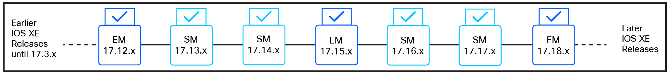
Reload support across SM and EM releases
● Supported upgrades occur between Extended Maintenance (EM) releases.
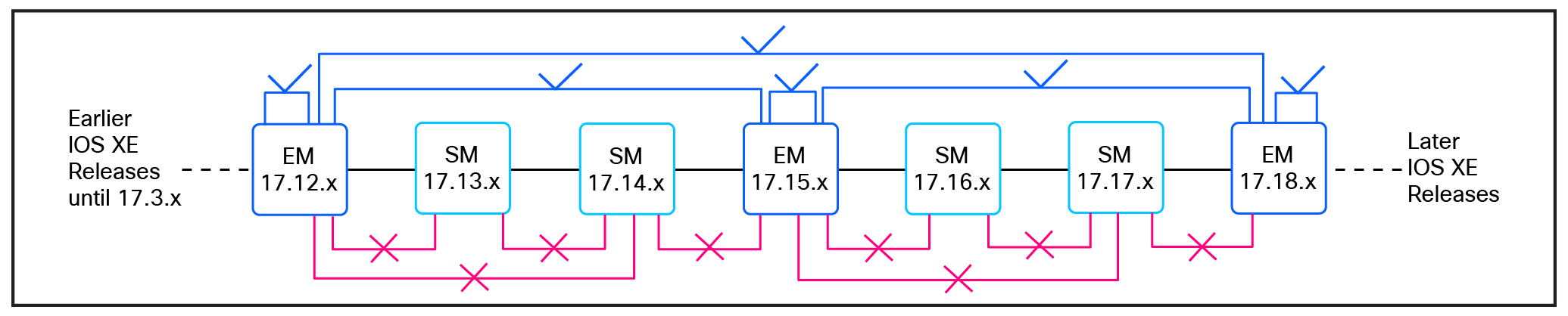
Upgrade support across EM releases
Note: Downgrade is not permitted.
Licensing requirements
● Standalone switches require a minimum of Network Essentials licensing; Advantage is supported for deployments requiring advanced features.
● Stacked switches require Network Advantage licensing.
Pre-upgrade eligibility validation
As part of every xFSU operation, the system automatically validates all required hardware, software, and topology prerequisites before proceeding.
For visibility and planning purposes, operators can optionally review the eligibility status in advance using the following command:
show xfsu eligibility
Note: Only systems reporting an eligible state should proceed with xFSU.
This command is available only in Cisco IOS XE Release 17.8 and later.
| Output example C9300_Switch# show xfsu eligibility Reload fast supported: Yes The following features are configured without the necessary GR support. This may cause control protocol flaps, leading to longer traffic loss during XFSU. * 1.BGP is not configured in GR Mode. Required Config " bgp graceful-restart " **************************************************************** Eligibility Check Status ================== ====== Autoboot Enabled Yes Install Mode Yes Spanning Tree Eligible MacSec Eligible
FAILED: FPGA on switch 1 does not support xFSU, please upgrade FPGA via normal install or upgrade hu-programmable fpga XFSU Eligibility Summary
============================== XFSU Eligibility: NOT ELIGIBLE ============================== |
Executing xFSU
xFSU offers two execution options: a software upgrade or a fast reload that preserves the current image.
Option 1: Execute xFSU for a software upgrade
Use the following command to upgrade the system software with xFSU:
install add file <image path> activate xfsu commit
Note: To suppress interactive confirmation prompts during execution, use:
install add file <image path> activate xfsu commit prompt-level none
Option 2: Execute xFSU for a reload
To reload the system using xFSU without changing the software version, use:
reload fast
Post-upgrade verification
1. After the xFSU operation completes, the following commands may be used to verify successful execution and system state:
show xfsu status
| Output example C9300_Switch# show xfsu status XFSU PLATFORM Status: Data plane update done, Upgrade done in 1590 ms. |
Note: In a stacked system, at least one control plane remains operational throughout the xFSU process. As a result, this command can also be used during the upgrade to monitor real-time progress and determine the current execution stage.
| Output example C9300_Switch# show xfsu status xFSU PLATFORM Status: Stack converged, waiting for standby reconnect ---- (OR) ----- xFSU PLATFORM Status: Stack reloaded, all nodes connected |
2. Verify successful completion of the xFSU operation by confirming the reload reason.
show version | include reason
Note: Expected output includes Image Install with Reloadfast or Reload Fast Command.
3. For further verification and troubleshooting, review system logs for entries confirming completion of the fast reload process.
show log | include FAST
Note: A successful operation includes the following log message: %FED_IPC_MSG-5-FAST_RELOAD_COMPLETE
Caveats
● MACsec is not supported. If configured, xFSU will not proceed.
● Compatible field-programmable gate array (FPGA): xFSU requires the switch to have a supported FPGA version. If the device is running an outdated or incompatible FPGA, the xFSU operation will not proceed.
TIP: FPGA compatibility verification:
● For devices running IOS XE Release 17.15.3 or later, FPGA eligibility can be validated directly using the following command:
show xfsu eligibility
The Supported FPGA field must display Yes for xFSU to proceed. If the device is running an outdated or unsupported FPGA, the xFSU operation will stop and display an error such as:
FAILED: FPGA on switch 1 does not support xFSU. Please upgrade the FPGA via a standard installation.
In these cases, a standard software upgrade must be performed to update the FPGA, during which traffic impact is expected.
● For devices running IOS XE Release 17.3.2a through 17.15.2, FPGA compatibility cannot be validated through the built-in command. Instead, an Embedded Event Manager (EEM)-based compatibility script, available through Cisco Technical Support, should be used to confirm whether the hardware FPGA meets the xFSU requirements.
● Technical note: For a comprehensive list of supported features,
see Understand Extended Fast Software Upgrade on Catalyst 9300 Series Switches
● Cisco Community Blog: Enhanced xFSU: Catalyst 9300 Traffic Downtime under 5 Seconds!