Cisco C9350 Series Smart Switches Architecture White Paper
Available Languages
Bias-Free Language
The documentation set for this product strives to use bias-free language. For the purposes of this documentation set, bias-free is defined as language that does not imply discrimination based on age, disability, gender, racial identity, ethnic identity, sexual orientation, socioeconomic status, and intersectionality. Exceptions may be present in the documentation due to language that is hardcoded in the user interfaces of the product software, language used based on RFP documentation, or language that is used by a referenced third-party product. Learn more about how Cisco is using Inclusive Language.
Enterprise campus networks are undergoing rapid transformation to support AI-driven workloads, advanced security requirements, and next-generation wireless technologies. The adoption of Wi-Fi 6 (802.11ax) and
Wi-Fi 7, combined with the increasing use of high-performance endpoints, is resulting in increased performance and capacity demands on access infrastructure. At the same time, organizations need platforms that deliver deterministic performance, integrated security, and simplified operations across hybrid and distributed environments. To meet these demands, the campus access layer must evolve beyond traditional switching to provide both scalability and intelligence natively within the network environment.
The Cisco® C9350 Series Smart Switches are purpose-built to deliver a secure, high-performance, and operationally unified access platform for modern enterprises. Built on a Cisco Silicon One™ Application- Specific Integrated Circuit (ASIC), the C9350 Series supports full Multigigabit Ethernet from 10 Mbps to 10 Gbps and delivers up to 90W of Power over Ethernet (PoE) on every port, helping ensure reliable operation for next-generation Wi-Fi access points, IoT devices, and power-intensive endpoints. With additional processing resources such as enhanced CPU, RAM, and SSD, the platform is hardware-ready for advanced on-box services such as AI-driven workloads and network visibility tools like Cisco ThousandEyes®, thereby reducing reliance on external servers or cloud infrastructure. The C9350 also integrates Post- Quantum Cryptography (PQC)-safe hardware anchored by a Trust Anchor module (TAm), delivering hardware-rooted trust and secure key storage for resilience against quantum-era threats. Designed for unified operations across on-premises, cloud, and hybrid environments, the C9350 simplifies licensing, enables consistent policy enforcement, and offers seamless manageability through the Cisco Catalyst™ Center or Cisco Meraki™ platform. Together, these capabilities establish the Cisco C9350 Series Smart Switches as a secure, sustainable, and future-ready access switching platform, designed to meet today’s enterprise campus performance demands while preparing for next-generation requirements such as quantum-safe security, AI-enabled workloads, and advanced programmability.
This white paper provides an architectural overview of the Cisco C9350 Series chassis, including system design, power, cooling, and storage options.
The Cisco C9350 Series platform consists of fixed-configuration enterprise access switches built on the Cisco Silicon One A100/L ASIC, delivering wire-speed forwarding with high buffer and low-latency performance. The platform runs on the open Cisco IOS® XE operating system, which supports model-driven programmability (YANG, NETCONF/RESTCONF), streaming telemetry, and automation workflows. With up to 16 GB of DRAM and 240 GB of SSD storage, the C9350 provides the capacity to host containers and extend functionality directly on the switch. At its foundation, the platform integrates a Trust Anchor module with PQC compliance, providing hardware-rooted trust, secure key storage, and long-term protection of sensitive operations such as device identity, key exchange, and certificate handling.
Building on this foundation, the C9350 Series incorporates platform-level resiliency by combining hardware and software safeguards to help ensure deterministic operation and continuous availability in enterprise access networks. On the software side, Cisco IOS XE introduces advanced high-availability features such as hardware-ready Extended Fast Software Upgrade (xFSU) for accelerated, hitless image upgrades, Stateful Switchover (SSO) for seamless control-plane failover, Software Maintenance Upgrades (SMU) for targeted patching, and Graceful Insertion and Removal (GIR) for minimal-impact maintenance. Complementing these, the hardware design supports up to three hot-swappable Titanium-rated power supplies in an N+1 redundant configuration with greater than 96% efficiency, alongside front-to-back airflow with modular, variable-speed fans that deliver both thermal stability and redundancy. Together, these capabilities create a resilient architecture that sustains performance and service continuity under varying load, maintenance, and fault conditions.
The C9350 Series is also designed with sustainability in mind, incorporating Titanium-rated power supplies with industry-leading efficiency, modular fans optimized for reduced power draw, and hardware designs that minimize material usage without compromising reliability. The platform supports energy-aware features such as granular power monitoring and intelligent PoE allocation, helping enterprises reduce their operational carbon footprint while maintaining performance. In addition, packaging and accessory optimizations align with Cisco’s broader sustainability strategy, reducing waste and improving lifecycle efficiency. This combination of resilient design, sustainable engineering, and future-ready cryptographic security positions the C9350 as a next-generation access platform built for both today’s enterprise needs and tomorrow’s environmental and compliance requirements.
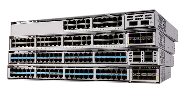
Cisco C9350 Series Smart Switches
Cisco C9350 Copper models
Data-only switches
● C9350-24T: Cisco C9350 Series Smart Switch with 1x Silicon One A100 ASIC and 24x 10M/100M/1G Ethernet ports with optional uplink modules.
● C9350-48T: Cisco C9350 Series Smart Switch with 1x Silicon One A100 ASIC and 48x 10M/100M/1G Ethernet ports with optional uplink modules.
● C9350-48TX: Cisco C9350 Series Smart Switch with 2x Silicon One A100 ASICs and 48x 10M/100M/1G/2.5G/5G/10G Ethernet ports with optional uplink modules.
PoE+ switches
● C9350-24P: Cisco C9350 Series Smart Switch with 1x Silicon One A100 ASIC and 24x 10M/100M/1G Ethernet ports with optional uplink modules.
● C9350-48P: Cisco C9350 Series Smart Switch with 1x Silicon One A100 ASIC and 48x 10M/100M/1G Ethernet ports with optional uplink modules.
Cisco UPOE® switches
● C9350-24U: Cisco C9350 Series Smart Switch with 1x Silicon One A100 ASIC and 24x 10M/100M/1G Ethernet ports with optional uplink modules.
● C9350-48U: Cisco C9350 Series Smart Switch with 1x Silicon One A100 ASIC and 48x 10M/100M/1G Ethernet ports with optional uplink modules.
Cisco UPOE+ switch
● C9350-48HX: Cisco C9350 Series Smart Switch with 2x Silicon One A100 ASICs and 48x 10M/100M/1G/2.5G/5G/10G Ethernet ports with optional uplink modules.
This section briefly describes the highlights of the Cisco C9350 Series chassis.
Multiple models are available to meet varied port speed, density, and scale requirements.
Power supplies: Supports up to three hot-swappable Power Supply Units (PSUs) in N+1 redundancy:
● 500W Platinum-rated
● 850W Platinum-rated
● 1600W Titanium-rated
Flexible PoE budget allocation, supporting simultaneous 90W PoE on all ports, with uninterrupted operation during PSU failure.
Cooling system: Modular fan trays with N+1 redundancy.
● Up to 30% higher airflow capacity for improved thermal headroom.
● Variable-speed fans adjust dynamically for cooling efficiency and reduced noise.
Supports 120-GB or 240-GB external SSD storage for application hosting, with DDR5 memory
(8-GB dedicated RAM) and a 35% faster CPU for enhanced performance and advanced on-box services.
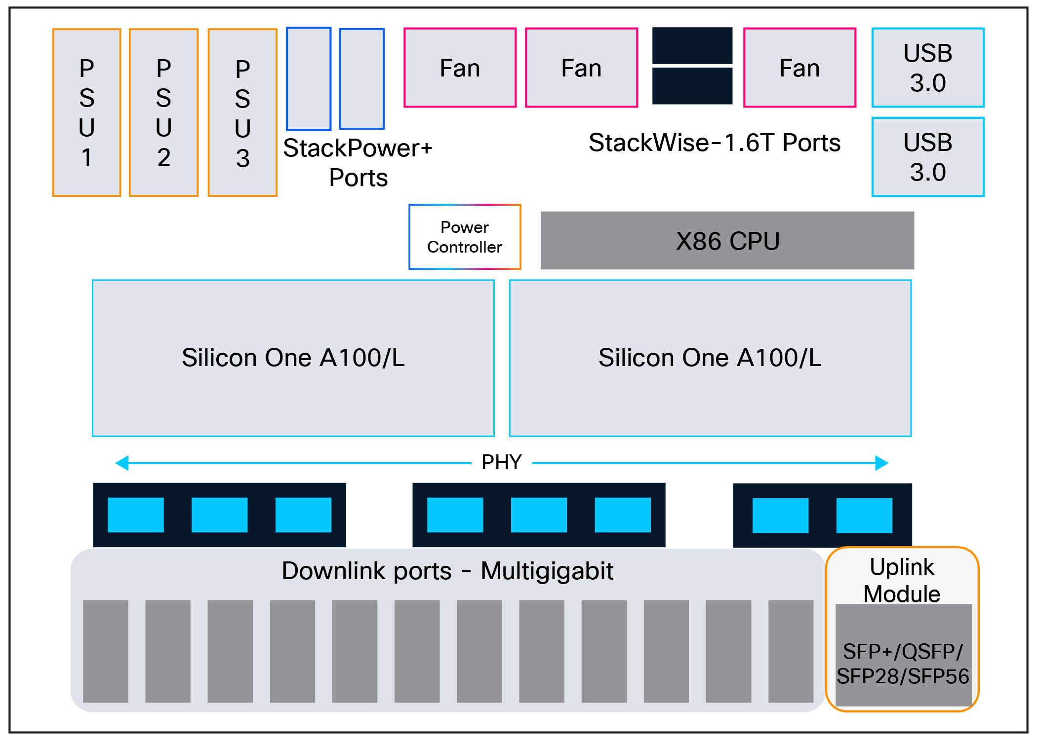
The Cisco C9350 Series is a fixed-configuration enterprise access switching platform with three field-replaceable PSU slots supporting AC input power options. The design allows PSU replacement without service interruption and uses modular, field-replaceable fan trays with variable speed to maintain stable thermal performance. Front-panel elements include a blue beacon LED, a multicolor system status LED, an RJ-45 console, a 1G Ethernet management port, a USB 3.0 Type A port, and a USB Type B console interface, with optional passive RFID for inventory tracking. The switches support Cisco StackWise®-1.6T for up to 1.6 Tbps stack bandwidth and StackPower connectors for shared power across stack members, with field-installable stack cables for flexible deployment.
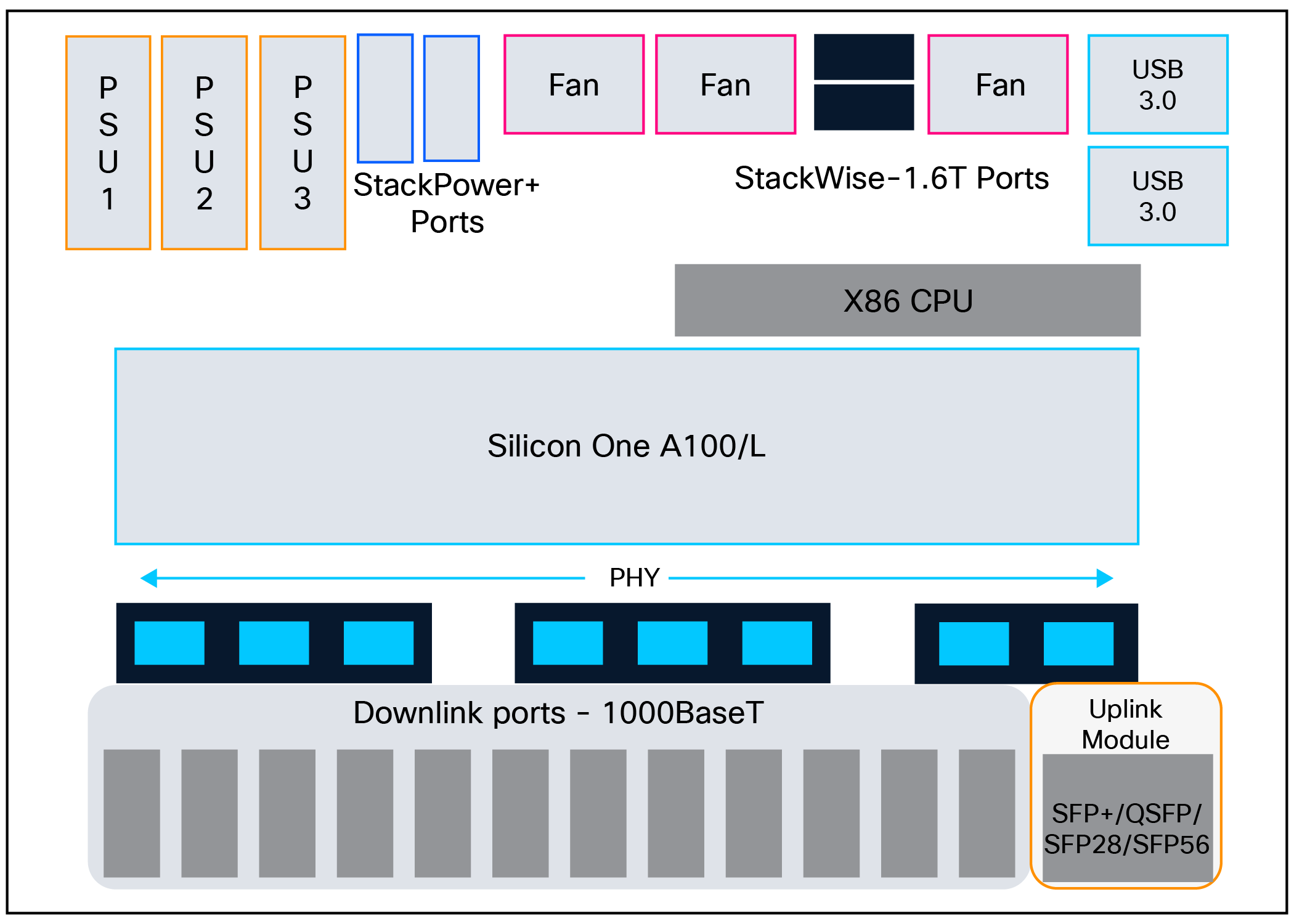
C9350-24T/48T board layout
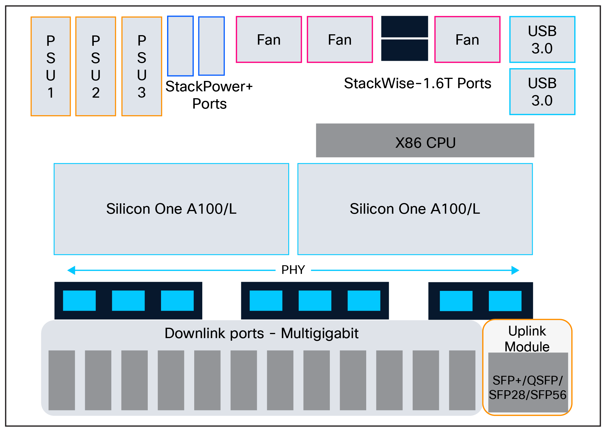
C9350-48TX board layout
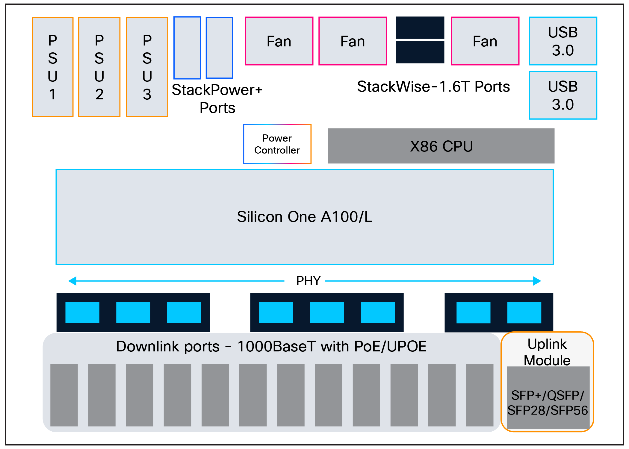
C9350-24P/24U/48P/48U board layout
C9350-48HX board layout
The Cisco C9350 Series features a flexible power architecture supporting up to three hot-swappable PSUs with options including 500W and 850W Platinum-rated and 1600W Titanium-rated models. The Titanium PSUs deliver market-leading efficiency, providing 4% greater efficiency than Gold-rated units at 50% load and 3% greater efficiency at 100% load, reducing power consumption and heat dissipation. The modular design enables flexible PoE scaling based on installed PSU combinations, supporting mixed configurations and operating in either single-PSU nonredundant mode or a multi-PSU load-sharing configuration. With maximum PSU configuration, the system can deliver UPOE+ (90W) across all 48 ports simultaneously, providing comprehensive power for high-demand devices. All models feature Online Insertion and Removal (OIR) capability for zero-downtime maintenance and expansion, while providing comprehensive support for UPOE and high-power PoE standards. This architecture helps ensure both operational continuity and investment protection through scalable power capacity and industry-leading energy efficiency.
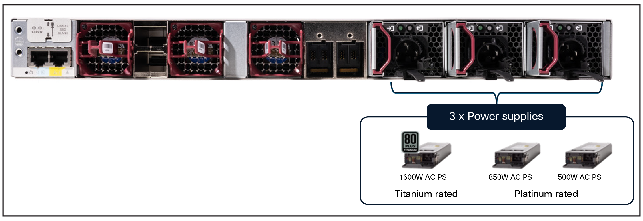
C9350 power supply options
On the C9350, power utilization is segmented into system power, reserved for core switch hardware, and PoE power, allocated to connected Powered Device (PD) endpoints. In the figure below, Allocated values represent reserved capacity derived from thermal conditions, ASIC/CPU load, PSU efficiency curves, and component tolerances, while Consumed values reflect the instantaneous power draw operating within device-defined thresholds. This reporting model provides deterministic visibility into available, allocated, and consumed power across both the switching infrastructure and powered devices.
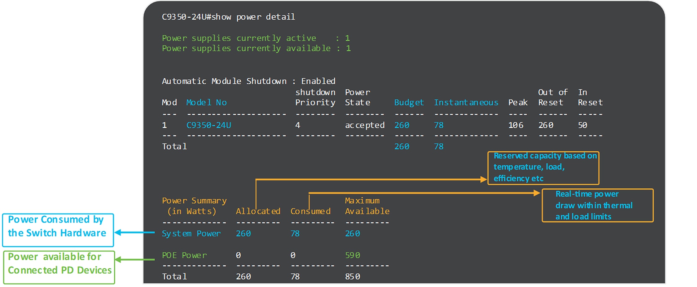
C9350 Power Management Overview Showing Allocated, Consumed, and Available Capacity
The Cisco Power Calculator (https://cpc.cloudapps.cisco.com/cpc/launch.jsp) helps determine the PoE budget required for a given C9350 deployment, factoring in system load and connected devices. The tool also provides heat dissipation metrics to support accurate capacity and thermal planning.
The maximum output power per power supply for the Cisco C9350 Series is listed below. Each PSU has a power holdup time of approximately 20 milliseconds at 100% load. Each comes with front-to-back variable-speed cooling fans and has a push-release lock for simple and secure OIR.
● 1600W AC PSU is 1200W at 110V and 1600W at 220V input.
● 850W AC PSU is 850W at 110V to 220V input.
● 500W AC PSU is 500W at 110V to 220V input.
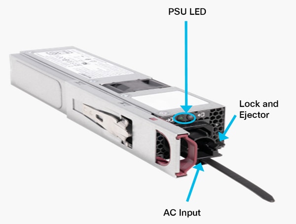
Power supply module
Table 1. PSU status LED indicatorsChassis cooling
| LED |
Color |
Status |
Description |
| AC |
|
Off |
No AC input power |
| AC |
|
On |
AC input power present |
| PS |
|
Off |
Output is disabled |
| PS |
|
On |
Power output to switch active |
| PS |
|
Fail |
Output has failed |
Cisco C9350 Series switches use three rear, hot-swappable, variable-speed fan modules (numbered left to right when viewed from the rear) that pull air from the front and sides to the rear. The fan unit cools the entire chassis and interfaces with environmental monitors to raise alarms when thresholds are exceeded, while each module’s built-in thermal sensors track ambient temperature and automatically adjust fan speed. A status LED at the top left of the fan assembly is green during normal operation and turns amber on failure. The system tolerates a single fan fault—running with two operational fans as the remaining units ramp up (with higher acoustic noise)— but the failed module should be replaced promptly to avoid a second-fault outage. If required cooling or fan presence cannot be maintained, the switch performs a controlled shutdown to prevent overheating.
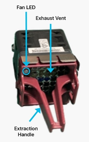
Fan module
Table 2. Fan status LED indicators
| LED |
Color |
Status |
Description |
| Fan |
|
Solid |
Fan/fans OK |
| Fan |
|
Solid |
Tachometer fault |
| Fan |
|
Solid |
One or more fans faulty (tachometer) Exceeded maximum limit |
The Cisco C9350 Series fan supports airflow from the front and sides to the back.
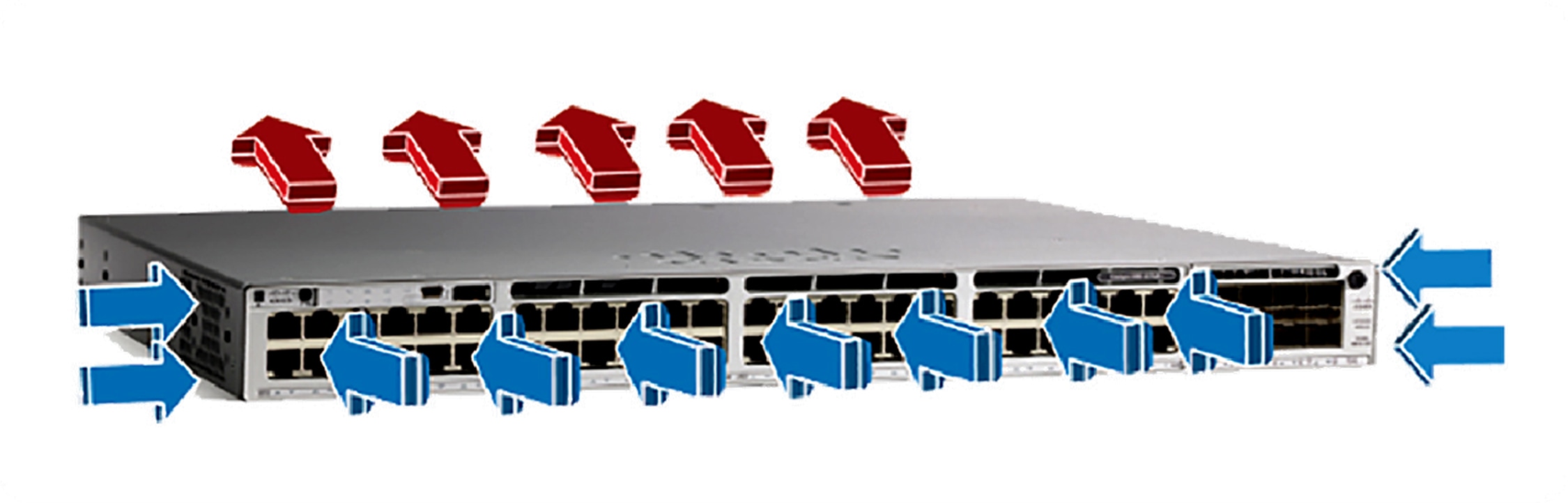
Switch airflow
The C9350 Series supports port-side and side-intake airflow across all SKUs, drawing cool air in through the port side and chassis sides (cold aisle) and exhausting it through the rear fan and power supply modules (hot aisle). Designed with flexible thermal management, the switches are also capable of supporting reverse airflow in the future, for deployment adaptability across diverse data center and wiring closet environments.
The Cisco C9350 Series consists of line-rate switches with configurable system resources that can be tuned for specific feature sets and deployment roles. The baseboard architecture centers on a Virtual Output Queuing (VOQ)-based Silicon One forwarding pipeline and includes the following main components:
● Silicon One A100/L ASIC
● x86 CPU complex: Control-plane processor.
● ASIC interconnect: High-bandwidth on-board links between the ASIC, front-panel PHYs, and system controllers.
● StackWise-1.6T.
● StackPower ports: Distributed power sharing and redundancy across the stack.
● Front-panel interfaces: Access and uplink ports with corresponding PHYs and MACs.
Silicon One A100/L ASIC
The Cisco C9350 Series is powered by the Silicon One A100/L (Argon) ASIC, part of the unified Silicon One family designed to deliver high-performance networking across multiple domains. In the C9350, the A100 is specifically optimized for enterprise access switching and is built on 16-nm process technology, enabling high performance with efficient power consumption. It is designed around a single-slice architecture, in which all forwarding capacity and resources are integrated into one slice, with traffic deterministically mapped based on port groupings. This ASIC delivers approximately 1.3 Tbps of bandwidth at ~1 GHz and ~1.5 Bpps throughput.
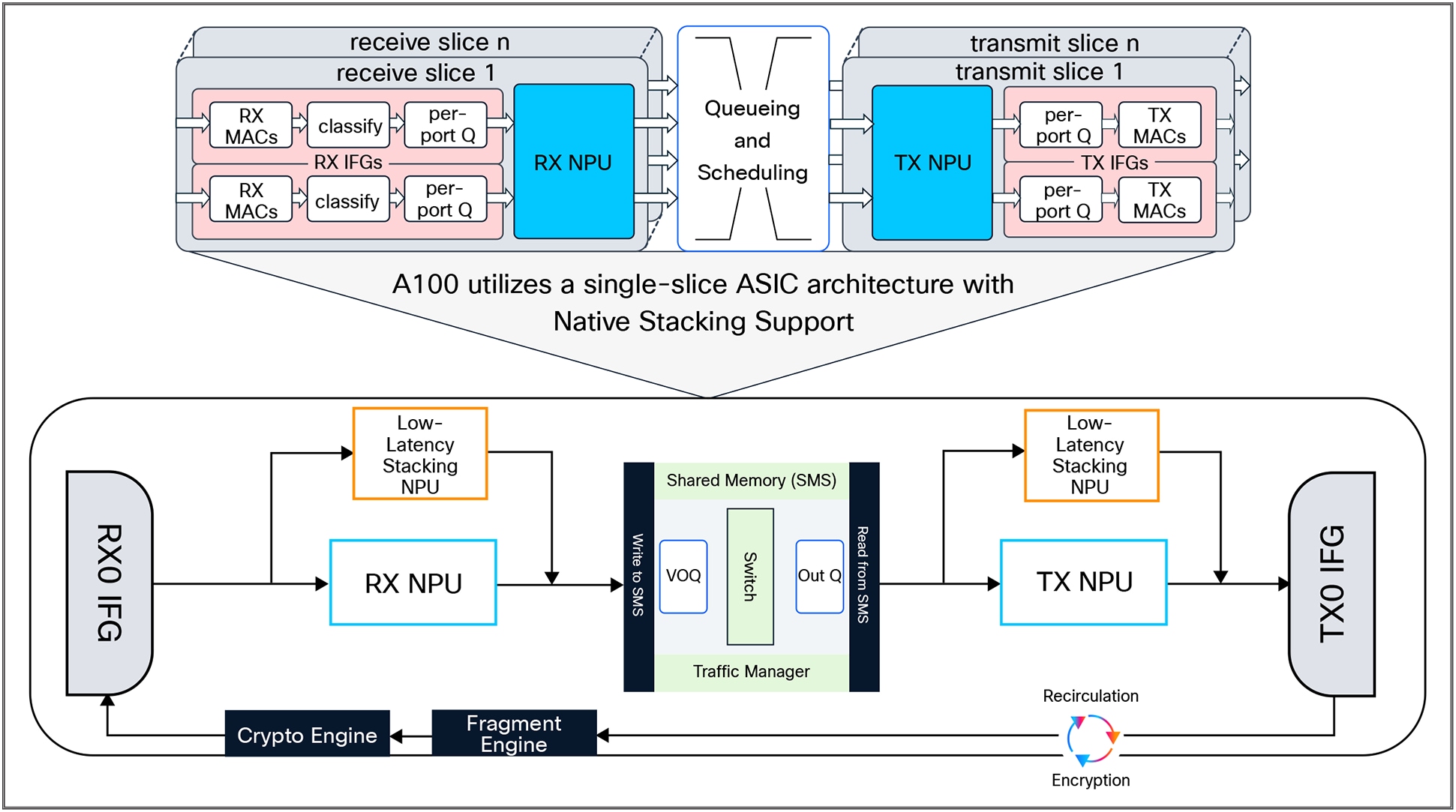
Cisco Silicon One A100 schematic
The Cisco C9350 employs a VOQ forwarding model to optimize traffic management and minimize packet loss during congestion. In this architecture, each input maintains a dedicated virtual queue for every output, helping ensure that congestion on one egress port affects only its corresponding queue while traffic to other destinations continues uninterrupted. A credit-based scheduler coordinates queue servicing to guarantee fair bandwidth allocation and efficient utilization, allowing traffic for uncongested ports to flow freely even under heavy load. By isolating traffic flows and applying intelligent scheduling, the VOQ model enhances performance, fairness, and congestion resilience across the C9350 switching fabric.
The architecture and functionality of the Cisco Silicon One A100/L ASIC in the C9350 Series represent a significant step forward compared to earlier platforms. The key A100/L capabilities are as follows:
● Packet bandwidth and switching throughput: ~1.3 Tbps at ~1 GHz.
● Forwarding performance: ~1.5 Bpps (500 Mpps via the Receive Network Processing Unit [Rx NPU] + 1 Bpps via the stacking engine).
● Stack bandwidth: 1.6 Tbps (StackWise-1.6T) with dedicated low-latency stacking.
● Forwarding Information Base (FIB): 256,000 IPv4 routes or 128,000 IPv6 routes (internal Longest Prefix Match [LPM]).
● Packet buffer: 18 MB on-chip.
● Dedicated NetFlow and Access Control List (ACL) resources: Up to 136,000 HCAM
(algorithmic TCAM) entries for ACLs, and NetFlow programmability.
Cisco Silicon One A100/L – Central databases
The Cisco Silicon One A100/L architecture in the C9350 Series integrates three specialized central databases within its forwarding pipeline: Longest Prefix Match (LPM), Central Exact Match (CEM), and HCAM (hash-based algorithmic TCAM). Together, these provide a unified, scalable, and deterministic approach to routing, forwarding, and policy enforcement for enterprise access networks.
● LPM (Longest Prefix Match)
◦ An SRAM-based database optimized for IP and mask routing lookups.
◦ Supports both IPv4 and IPv6 unicast routing (single entry for IPv4, dual entry for IPv6).
◦ Scales to 256,000 IPv4 or 128,000 IPv6 routes on-chip, helping ensure consistent wire-speed forwarding for large routing tables.
● CEM (Central Exact Match)
◦ An SRAM-based database for MAC addresses, host routes (/48, /32, /128), multicast, and label lookups.
◦ Implements an exact match algorithm for deterministic, bit-precise lookups.
◦ Provides scale of 256,000 IPv4 or 128,000 IPv6 entries, with flexible reallocation across tables to match evolving requirements.
● HCAM (hash-based algorithmic TCAM)
◦ A hybrid of TCAM and hash-based exact match tiles that delivers the speed and flexibility of TCAM with the efficiency and scalability of hash tables.
◦ Provides 8000 native TCAM entries combined with 128,000 algorithmic tiles that can be dynamically allocated across ACLs, Quality of Service (QoS), and NetFlow.
◦ More memory-dense and power-efficient than traditional TCAMs, while still maintaining deterministic wire-speed performance.
◦ Eliminates rigid partitioning, reducing fragmentation and improving overall utilization of hardware resources.
Note: Static Random-Access Memory (SRAM) is high-speed, low-latency memory used in ASICs for deterministic lookup operations, making it ideal for storing routing, forwarding, and policy tables where performance consistency is critical.
By combining LPM for scalable routing, CEM for deterministic exact matches, and HCAM for policy enforcement, the Cisco Silicon One A100/L enables the C9350 Series to deliver a high-capacity, flexible, and efficient forwarding architecture. This design helps ensure that the platform can meet the growing needs of segmentation, security, and telemetry in modern enterprise access networks, while offering greater scalability and efficiency than legacy fixed-profile TCAM systems.
X86 CPU complex
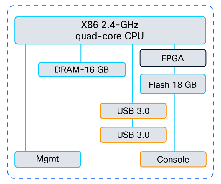
CPU complex schematic
The Cisco C9350 Series Switches are equipped with the same x86 CPU, system memory, and flash storage.
Highlights include:
● Quad-core 2.4-GHz x86 CPU.
● Single 16 GB of DDR5 RAM.
● Support for USB Type C file system (back serviceable) for external storage and Bluetooth dongle.
● Support for USB Type C serial console in addition to the RJ-45 serial console.
● 18 GB of internal Enhanced USB (eUSB) flash.
● USB 3.0 (400 MBps read and 140 MBps write) or M.2 (300 MBps read and 290 MBps write) form-factor SSD module (rear serviceable) for application hosting or general-purpose storage.
● System reset switch for manual power cycle.
ASIC interconnects
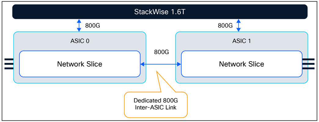
The Cisco C9350 Series Smart Switches are powered by the Cisco Silicon One A100/L ASIC and are available in both single-ASIC and dual-ASIC models. In single- ASIC systems, all front-panel ports are locally switched within the ASIC, eliminating the need for an ASIC interconnect. In dual-ASIC systems, traffic between ports on different ASICs is transported across the integrated ASIC interconnect, providing deterministic forwarding and efficient utilization of resources.
Single-ASIC schematic
Dual-ASIC schematic
StackWise-1.6T
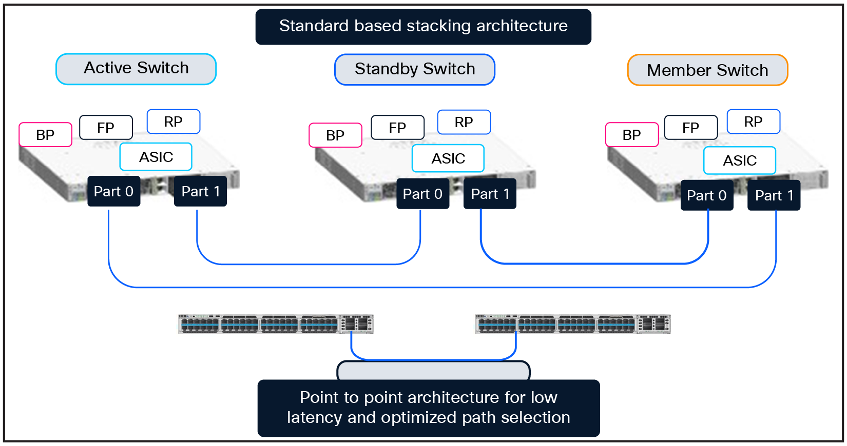
The Cisco C9350 Series introduces StackWise-1.6T, a next-generation stacking architecture delivering up to 1.6 Tbps of stack bandwidth. By connecting multiple switches using dedicated high-speed StackWise ports at the rear, the system combines up to eight switches into a single logical switch, simplifying operations while providing higher port density and resilient system design.
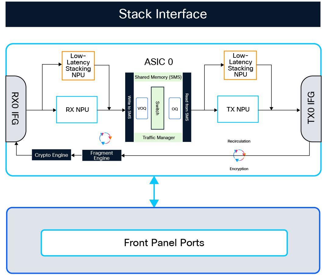
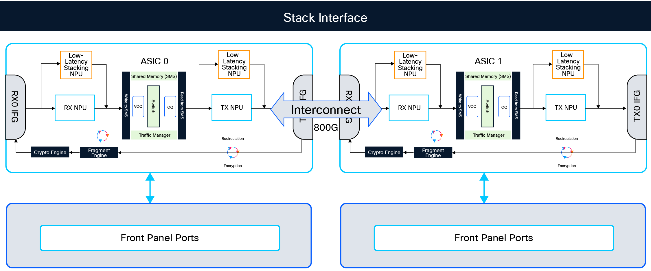
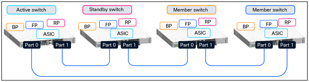
C9350 Series Smart Switches Stacking Architecture
StackWise-1.6T employs a dedicated low-latency stacking Network Processing Unit (NPU) within the Cisco Silicon One A100 ASIC, delivering wire-rate forwarding across all stack members. Using a VXLAN encapsulation Shortest-Path Forwarding (SPF)-based stacking mechanism, it helps ensure low latency, guaranteed bandwidth, and resilient performance. Stack traffic can be load-balanced or can follow SPF, and link failures impact only directly connected members while others continue at full bandwidth.
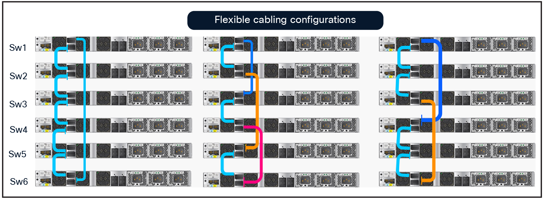
C9350 Series Smart Switches flexible StackWise cabling configuration options (Considering 6 switches in Stack)
As in earlier generations, a unified control and management plane is created by electing an active switch and a standby switch, with the remaining switches acting as members. The active switch handles all Layer 2 and Layer 3 control functions and synchronizes state information with the standby, enabling Stateful Switchover (SSO) and Nonstop Forwarding (NSF) for seamless resiliency. Forwarding remains distributed, as each switch continues to leverage its local ASIC resources for data plane operations.
StackWise-1.6T highlights for the C9350 Series
● Up to eight C9350 switches can be stacked as a single system.
● 1.6-Tbps stack bandwidth with deterministic low-latency performance.
● Dedicated stacking NPU inside the A100/L ASIC for 1.6T throughput.
● Support for SSO/NSF across all major protocols.
● No packet size limitations; packet type agnostic.
● Distributed forwarding across all stack members.
StackPower+
On the C9350 platform, StackPower+ pools the available power from multiple switches into a shared budget and redistributes it instantly if a PSU fails or load spikes, helping avoid interruptions to PoE and system operation. It uses dedicated rear StackPower ports and cables and supports up to four switches per power stack. In larger deployments, a StackWise- 1.6T data stack can be partitioned into multiple power stacks—for example, an eight-member data stack can be organized as two power stacks of four to leverage all members.
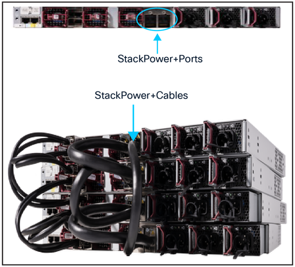
StackPower+ ports and cables
StackPower+ leverages 55A-rated stack cables and enhanced Stackpower port to provide high-capacity, fault-tolerant power distribution optimized for dense PoE, UPOE, and UPOE+ deployments. Compared to previous StackPower implementations, StackPower+ delivers over 35% higher effective power availability, simplifying pool-based power management and enabling scalable, resilient power delivery across the stack. Cisco StackPower+ supports two operating modes: shared and redundant.
In shared mode (default), the output of all installed PSUs is pooled, and the full budget is available anywhere in the power stack. If a PSU fails, the remaining pooled capacity continues to power the system and PoE loads with no impact, provided the overall budget still covers demand.
In redundant mode, the capacity of the largest PSU is reserved as backup and subtracted from the usable budget. This lowers the available power for normal operation but helps ensure immediate fallback capacity if a PSU fails.
Front panel interfaces
Ethernet PHY (physical layer) connects a link layer device (often a MAC) to a physical medium such as a transceiver. PHY on the Cisco C9350 Series Smart Switches is a fully integrated Ethernet transceiver supporting steering and mapping of lanes back to the ASIC to support multiple speeds (1G, 10G, 25G, 40G, 50G, and 100G Ethernet), depending on the optics inserted on the front-panel ports.
Highlights of the C9350-24T, -24P, and-24U switches
● 24T models offer up to 1G data on all ports.
● 24P models offer PoE+ (30W) on all ports.
● 24U models offer UPOE (60W) on all ports.
● 24x 10M/100M/1G RJ-45 Ethernet ports on a single A100/L ASIC.
● Modular uplink architecture delivering up to 200 Gbps total uplink bandwidth (with the C9350-NM-2C or C9350-NM-8Y network module).
● Provides deployment flexibility for environments requiring standard data connectivity, PoE for access devices, or high-power UPOE endpoints.
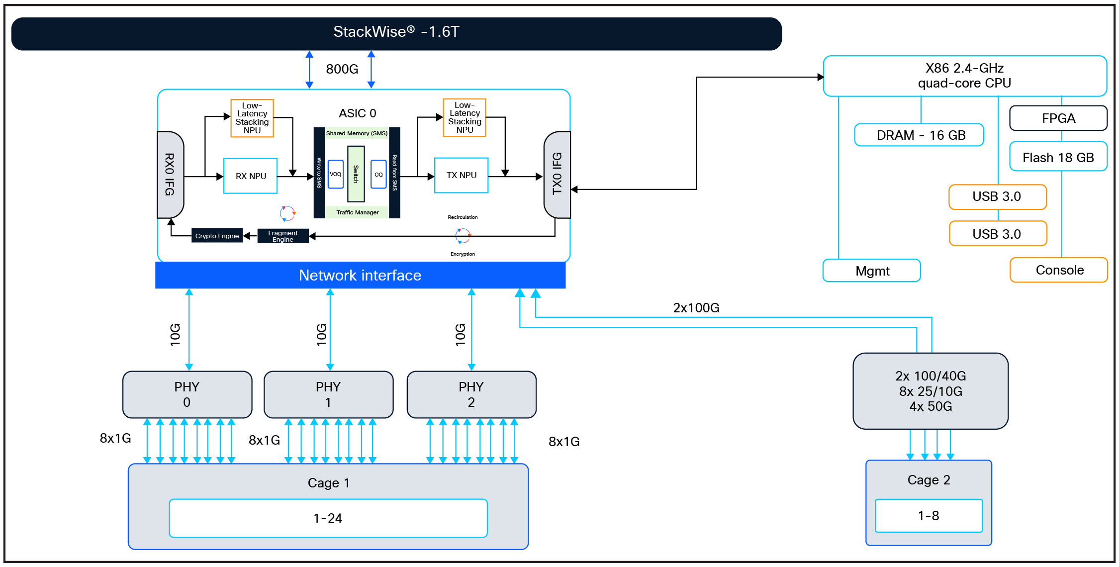
24-port switch schematics
Highlights of the C9350-48T, -48P, and -48U switches.
● 48T models offer up to 1G data on all ports.
● 48P models offer PoE+ (30W) on all ports.
● 48U models offer UPOE (60W) on all ports.
● 48x 10M/100M/1G RJ-45 Ethernet ports on a single A100/L ASIC.
● Modular uplink architecture delivering up to 200 Gbps total uplink bandwidth (with a C9350-NM-2C or C9350-NM-8Y network module).
● Scales up to 384 ports in a single stack, delivering high-density access with flexible support for standard data, PoE, and UPOE endpoints such as Wi-Fi 6/6E access points, IP phones, security cameras, and IoT devices—all with simplified management and resilient operations.
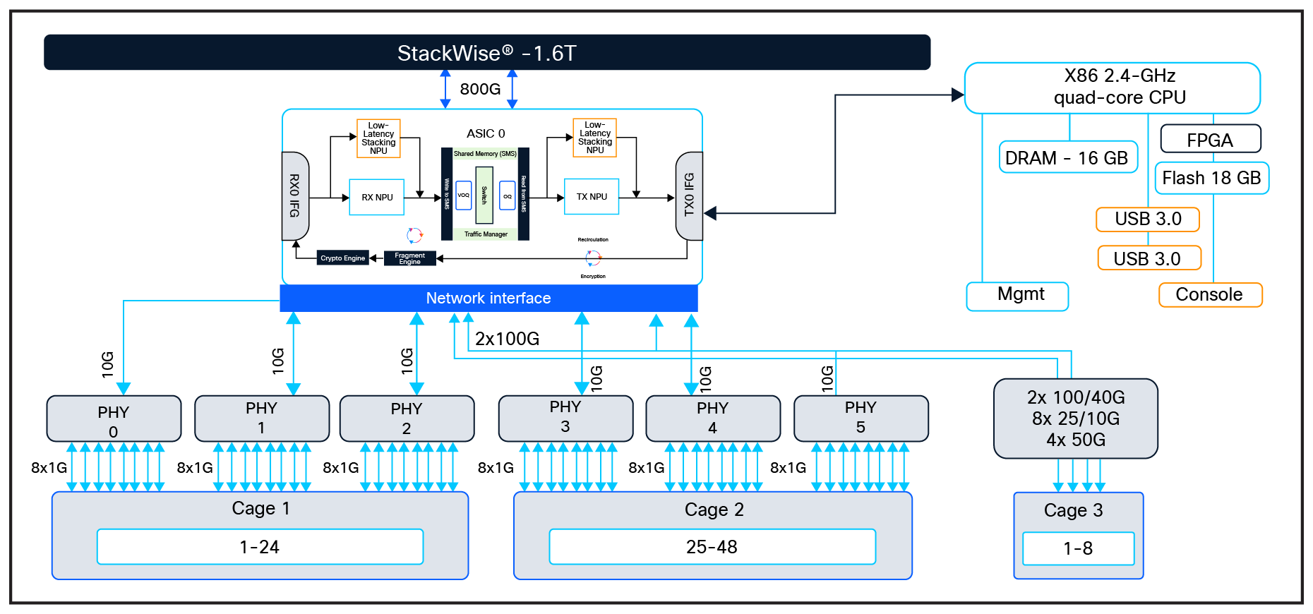
48-port single-ASIC switch schematics
Highlights of the C9350-48TX and -48HX switches.
● 48TX model delivers Multigigabit data (10M/100M/1G/2.5G/5G/10G) on all ports.
● 48HX model provides UPOE+ (90W, IEEE 802.3bt Type 4) on all ports, with a 4320W total PoE budget.
● 48x Multigigabit (10M/100M/1G/2.5G/5G/10G) on all ports across dual A100/L ASICs (10 Mbps full duplex only).
● Modular uplink architecture delivering up to 400 Gbps total uplink bandwidth (with a C9350-NM-4C, C9350-NM-2C, or C9350-NM-8Y network module).
● Delivers up to 448 Multigigabit 10G ports in an 8-member stack, enabling Wi-Fi 7 at scale while powering AI-driven workloads and smart building ecosystems with UPOE+ support for IoT sensors, cameras, lighting, and automation systems.
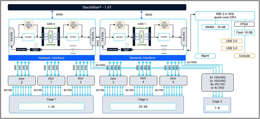
48-port dual-ASIC switch schematics
Network modules
The Cisco C9350 Series supports a range of modular uplink network modules, giving customers flexibility to choose the right mix of port speeds and media types. Network modules are not included by default and can be added as required. All ports on the C9350 uplink modules operate at line rate and support the same software features as the downlink ports, helping ensure consistent performance and feature parity across the system.
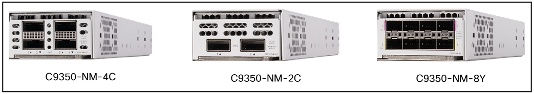
Network modules
Highlights of the C9350 network modules
● Uplink modules are supported on all C9350 modular uplink models.
● Modules are automatically powered upon insertion.
● Support for online insertion and removal for operational flexibility.
● ACT2 authentication helps ensure hardware integrity and trust.
● Line-rate performance on every port with support for 1G/10G/25G/40G/50G/100G single-flow traffic.
● Port speed is auto-negotiated based on the optics installed.
● C9350-NM-8Y can operate as eight 1G/10G/25G or four 50G.
For supported SFP modules, see tmgmatrix.cisco.com.
Storage
Enterprise networks rely on applications for a wide range of business-critical functions, including administrative tools such as performance monitors and protocol analyzers, as well as security toolsets like intrusion detection systems. Traditionally, these applications have been hosted on external physical or virtual servers, but the Cisco C9350 Series extends these capabilities directly onto the switch.
The C9350 supports SATA SSD modules, which serve as the primary storage for application hosting and also provide general-purpose storage for packet captures, operating system trace logs, and graceful insertion and removal snapshots. Unlike internal flash storage— which is not intended for third-party applications due to file system limitations—the SSD supports EXT2 and EXT4 file systems (EXT4 by default), enabling robust application hosting.
Applications hosted on the C9350 Series can include automation frameworks, configuration management agents, monitoring services, and integrations with enterprise toolchains. The platform leverages the Cisco IOx framework (a combination of Cisco IOS XE and Linux) to support containerized applications in Docker, LXC, or KVM-based virtual machines. Cisco IOS XE dedicates memory and CPU resources to application hosting, isolating user applications from system processes to maintain the performance and integrity of the switch’s control and data plane operations.
Table 3. C9350 resources for application hosting
| Platform |
Memory |
CPU |
USB 3.0 |
| C9350 |
16 GB DDR5 |
1x 2.4 GHz |
240 GB |
The Cisco C9350 Series Smart Switches’ support for a field-replaceable USB 3.0 SSD on the rear of the chassis provides an extra 240 GB storage. The USB 3.0 SSD is enabled with SMART (Self-Monitoring, Analysis, and Reporting Technology) to monitor the reliability of the drive, predict drive failures, and carry out different types of drive self-tests. The USB 3.0 SSD module has a 240-GB partition, and Cisco IOS XE Software creates a partition with EXT4 as the default file system.
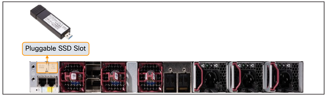
Location of SSD slot
Table 4. C9350 SSD specifications
| Capabilities |
|
| Form factor |
M2 SATA |
| Capacity |
240 GB |
| Performance |
300 MB/s read, 290 MB/s write |
| Power write |
4.5W |
| Security |
Hardware-based AES-256-bit |
This section provides a high-level overview of packet forwarding on the Cisco C9350 Series Smart Switches.
Unicast forwarding in the Silicon One A100/L ASIC.
Intra-ASIC (within the ASIC) packet walk.
Since all C9350 models leverage the Cisco Silicon One A100/L ASIC, the packet walk is described using a single unicast forwarding example.
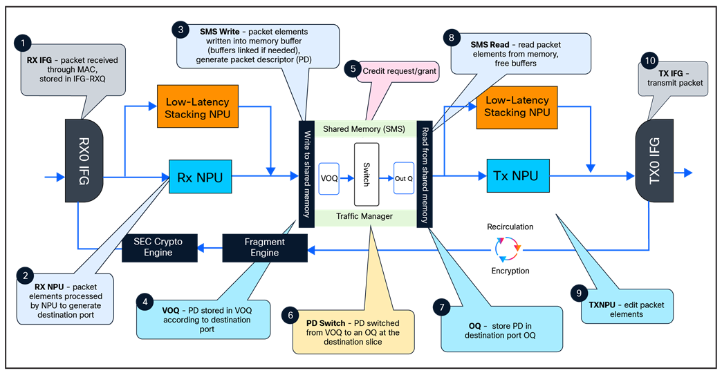
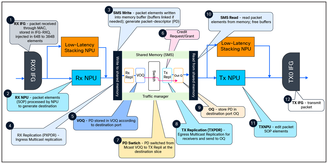
Unicast packet walk in Silicon One A100/L ASIC
1. Packet arrives at ingress port; PHY converts the signal, serializes the bits, and then sends the packet to the Receive Interface Group (Rx IFG) through the backplane.
2. The packet’s Start-of-Packet (SOP) fragment (64B to 384B elements) is processed by the Receive Network Processing Unit (Rx NPU) to determine the destination port. Non-SOP fragments bypass the Rx NPU and are passed directly to the Shared Memory Packet Buffer (SMS).
3. The packet is stored in the SMS, and a corresponding Packet Descriptor (PD) is generated.
4. The PD is stored in the Virtual Output Queue (VOQ) according to the destination port.
5. The VOQ requests credits from the destination Output Queue (OQ).
6. Once credit is granted from the OQ, the VOQ passes the PD to the slice crossbar.
7. The PD is then switched by the crossbar and is stored in the destination OQ.
8. The PD is scheduled from the OQ and presented to the SMS. The packet is then read out to the Transmit Network Processing Unit (Tx NPU).
9. The packet is processed by the Tx NPU by editing the packet’s SOP elements.
10. The packet is then transmitted out of an interface within a Tx IFG.
Inter-ASIC packet walk
Inter-ASIC packet walk
1. Packet arrives at the line card’s ingress port; PHY converts the signal, serializes the bits, and then sends the packet to the Receive Interface Group (Rx IFG) through the backplane.
2. The packet’s Start-of-Packet (SOP) fragment (64B to 384B elements) is processed by the Receive Network Processing Unit (Rx NPU) to determine the destination port. Non-SOP fragments bypass the Rx NPU.
3. The packet is stored in the Shared Memory Packet Buffer (SMS), and a corresponding Packet Descriptor (PD) is generated.
4. The PD is stored in the Virtual Output Queue (VOQ) according to the destination port.
5. The VOQ scheduler requests credits from the destination OQ across the inter-ASIC link.
6. When credits are granted, the VOQ dequeues the packet descriptor and forwards it through the inter- ASIC link to the egress ASIC’s slice, where it is enqueued in the destination OQ.
7. The PD is scheduled from the OQ and presented to the SMS. The packet is then read out to the Transmit Network Processing Unit (Tx NPU).
8. The packet is processed by the Tx NPU by editing the packet’s SOP elements.
9. The packet is then transmitted out of an interface within a Tx IFG.
Multicast forwarding in the Silicon One A100/L ASIC
The figure below shows the basic sequence of events when packets enter the Cisco C9350 Series front-panel ports for multicast forwarding within the single Cisco Silicon One A100/L ASIC.
Multicast packet walk
1. Packet arrives at the ingress port; PHY converts the signal, serializes the bits, and then sends the packet to the Receive Interface Group (Rx IFG) through the backplane.
2. The packet’s Start-of-Packet (SOP) fragment (64B to 384B elements) is processed by the Receive Network Processing Unit (Rx NPU) to determine the destination port. Non-SOP fragments bypass the Rx NPU and are passed directly to the Shared Memory Packet Buffer (SMS).
3. The packet is stored in the SMS, and a corresponding Packet Descriptor (PD) is generated.
4. Receive replication (RXPDR) is processed for ingress replication. Each copy made by RXPDR results in an enqueue into the Virtual Output Queue (VOQ).
5. The replicated PDs are stored in the VOQ according to the destination ports.
6. The VOQ requests credits from the destination Output Queue (OQ).
7. Once credit is granted from the OQ, the VOQ passes the PD to the slice crossbar.
8. The PD is then switched by the crossbar and sent to Transmit Replication (TXPDR) for egress multicast replication.
9. Once the packet is replicated, it is stored in the destination OQs.
10. The PD is scheduled from the OQ and presented to the SMS. The packet is then read out to the Transmit Network Processing Unit (Tx NPU).
11. The packet is processed by the Tx NPU by editing the packet’s SOP elements.
12. The packet is then transmitted out of an interface within an Tx IFG.
Stack packet forwarding on the C9350 Series Smart Switches
Stack packet forwarding
1. Packet arrives on the source switch’s ingress port; the PHY deserializes it and forwards the frame to the Receive Interface Group (Rx IFG).
2. The Start-of-Packet (SOP) fragment is parsed by the Receive Network Processing Unit (Rx NPU), which identifies that the destination egress port resides on a different stack member; a Packet Descriptor (PD) is created.
3. The packet is stored in the Shared Memory Buffer (SMS) and the PD is enqueued in the Virtual Output Queue (VOQ) associated with the stack egress link; stack/TM/NPU headers are prepared for forwarding.
4. The VOQ requests credits from the destination Output Queue (OQ) on the target switch over the stack control channel.
5. Once credit is granted by the destination OQ, the VOQ forwards the PD through the local fabric slice to the stack port.
6. The encapsulated packet is transmitted over the stack link toward the destination switch (intermediate members, if any, examine only the stack header and forward it hop by hop).
7. The destination switch receives the packet on its stack port; the Rx NPU validates the stack header and delivers the PD to the local traffic manager.
8. The PD is placed in the destination OQ for the correct egress interface; when scheduled, the OQ presents the PD to the SMS and the packet is read out to the Transmit NPU (Tx NPU).
9. The Tx NPU removes the stack/TM/NPU headers and applies required egress edits (rewrite, Quality of Service [QoS], TTL, etc.).
10. The packet is transmitted out of the destination front panel interface within a Tx IFG.
The Cisco C9350 Series Smart Switches are purpose-built to power the future of enterprise workplaces, delivering secure, deterministic access with Multigigabit performance and 90W PoE/UPOE+ to support next-generation endpoints. Built on the Cisco Silicon One A100/L ASIC, the platform combines PQC-compliant hardware security, simplified unified management across Catalyst Center and Meraki, and StackWise-1.6T scalability to 448 ports for dense campus environments. With integrated telemetry, programmability, and resources to host on-box advanced applications, the C9350 Series provides a resilient and future-ready foundation for secure, intelligent, and simplified enterprise networks.
The following websites offer more details on the Cisco C9350 Smart Series Switches and their capabilities.
● Cisco C9350 Series Switches Data Sheet.
● Cisco Silicon One Product Family White Paper.