FlashStack with Cisco UCS C890 M5 Rack Server for SAP HANA TDI
Available Languages
Bias-Free Language
The documentation set for this product strives to use bias-free language. For the purposes of this documentation set, bias-free is defined as language that does not imply discrimination based on age, disability, gender, racial identity, ethnic identity, sexual orientation, socioeconomic status, and intersectionality. Exceptions may be present in the documentation due to language that is hardcoded in the user interfaces of the product software, language used based on RFP documentation, or language that is used by a referenced third-party product. Learn more about how Cisco is using Inclusive Language.
The FlashStack solution is a validated, converged infrastructure developed jointly by Cisco and Pure Storage. The solution offers a predesigned data center architecture that incorporates computing, storage, and network design best practices to reduce IT risk by validating the architecture and helping ensure compatibility among the components. The FlashStack solution is successful because of its ability to evolve and incorporate both technology and product innovations in the areas of management, computing, storage, and networking. This document covers the design details for incorporating the Cisco Unified Computing System™ (Cisco UCS®) C890 M5 Rack Server into FlashStack for SAP HANA Tailored Data Center Integration (TDI).
With the dramatic growth in the amount of data in recent years, organizations need larger solutions to keep and manage their data. Based on the Second Generation (2nd Gen) Intel® Xeon® Scalable processors, the high-performance Cisco UCS C890 M5 server is well suited for mission-critical business scenarios such as medium-size and large SAP HANA database management systems with high availability and secure multitenancy. Under the SAP conditions for SAP HANA TDI the Cisco® solution provides a robust platform for SAP HANA workloads in either single node (scale up) or multiple node (scale out) configurations.
The SAP HANA platform provides a scalable database with advanced analytical capabilities and intuitive application-development tools in an in-memory data platform. SAP HANA supports nonvolatile Intel® Optane™ Persistent Memory (PMem), which brings together the low latency of memory and the persistence of storage. Persistent memory modules provide faster access to data and retain data across power cycles.
If you are interested in understanding FlashStack design and deployment details, including the configuration of various design elements and associated best practices, please refer to Cisco Validated Designs for FlashStack at: https://www.cisco.com/c/en/us/solutions/design-zone/data-center-design-guides/data-center-design-guides-all.html#FlashStack.
The section provides an overview of the solution discussed in this document.
Introduction
The Cisco UCS C890 M5 server provides a pre-validated, read-to-deploy infrastructure, reducing the time and complexity involved in configuring and validating a traditional data center deployment. The reference architecture described in this document highlights the resiliency and ease of deployment of an SAP HANA solution using a new or existing FlashStack setup.
The SAP HANA in-memory database combines transactional and analytical SAP workloads and hereby takes advantage of low-cost main memory and the data-processing capabilities of multicore processors, and faster data access. The Cisco UCS C890 M5 Rack Server is equipped with the 2nd Intel® Xeon® Scalable processors and supports DDR4 only memory modules or a mixture with Intel Optane PMem.
The eight-socket rack server integrates seamlessly into FlashStack and demonstrates the resiliency and ease of deployment of an SAP HANA TDI solution using FlashStack. The Pure Storage FlashArray//X enterprise storage provides ready to use file sharing capabilities without compromise, thus enabling distributed SAP HANA scale-out deployments. It enables organizations to consolidate their SAP landscape and run SAP application servers as well as multiple SAP HANA databases hosted on the same infrastructure.
Audience
The intended audience of this document includes IT architects and managers, field consultants, sales engineers, professional services staff, partner engineers, and customers who want to deploy SAP HANA on Cisco UCS C890 M5 Rack Servers.
Purpose of this document
This document provides design guidance for the integration of the Cisco UCS C890 M5 Rack Server into a FlashStack solution. The document introduces various design elements and addresses various considerations and best practices, including design and product requirements for a successful deployment. In addition, this document provides high-level steps for deploying and configuring SAP HANA on Cisco C890 M5 Rack Server. It showcases one of the variants of FlashStack for SAP HANA TDI.
External references are provided wherever applicable, but readers are expected to be familiar with the technology, infrastructure, and database security policies of the customer installation and have access to the product knowledge bases to review changes made after the release of this document.
Solution summary
FlashStack for SAP HANA TDI with the Cisco UCS C890 M5 Rack Server is a flexible, converged infrastructure solution designed to support mission-critical workloads for which performance and memory size are key attributes. The seven-rack-unit (7RU) form-factor rack server delivers exceptional performance, supporting eight 2nd Gen Intel Xeon processors and 96 DIMM slots, which can be populated either with DRAM only or in combination with Intel Optane PMem. The standard hardware configuration of the Cisco UCS C890 M5 Rack Server for SAP HANA enables the server for SAP HANA TDI deployments.
Like all other FlashStack solution designs, FlashStack with the Cisco UCS C890 M5 server can be configured according to your demands and use. You can purchase exactly the infrastructure you need for your current application requirements and then can scale up by adding more resources to the FlashStack system or scale out by adding more servers.
The Intelligent Platform Management Interface (IPMI) provides remote access for multiple users and allows you to monitor system health and to manage server events remotely. Cisco Intersight™ functions for the Cisco UCS C890 M5 Rack Server will be made available through future software updates. Cloud-based IT operations management simplifies SAP environments.
This section provides a technical overview of the computing, network, storage, and management components in this SAP solution. For additional information about any of the components discussed in this section, refer to the “For more information” section at the end of this document.
FlashStack infrastructure overview
Many enterprises today are seeking pre-engineered solutions that standardize data center infrastructure, offering organizations operational efficiency, agility, and scale to address cloud and bimodal IT and their business requirements. Their challenges are complexity, diverse application support, efficiency, and risk. FlashStack addresses all the challenges with these features:
● Stateless architecture, providing the capability to expand and adapt to new business requirements
● Reduced complexity, automatable infrastructure, and easily deployed resources
● Robust components capable of supporting high-performance and high bandwidth virtualized and non-virtualized applications
● Efficiency through optimization of network bandwidth and inline storage compression with deduplication
● Risk reduction at each level of the design with resiliency built into each touch point
Cisco and Pure Storage have partnered to deliver several Cisco Validated Designs, which use best-in-class storage, server, and network components to serve as the foundation for multiple workloads, enabling efficient architectural designs that you can deploy quickly and confidently.
FlashStack components
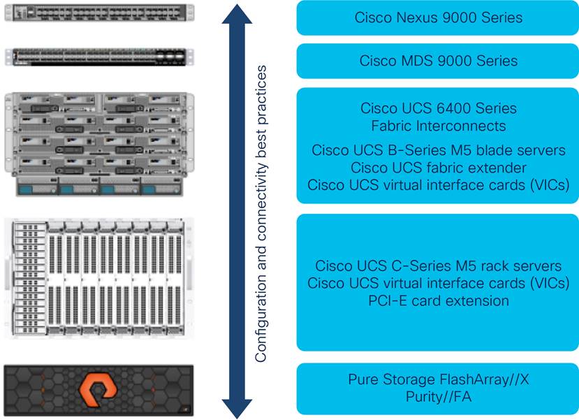
The FlashStack architecture is built using the following infrastructure components for computing, networking, and storage (Figure 1. ):
● Cisco UCS B-Series Blade Servers and C- Series Rack Servers
● Cisco Nexus® Family switches
● Cisco MDS 9000 Family switches
● Pure Storage FlashArray//X
FlashStack components
All FlashStack components are integrated, so you can deploy the solution quickly and economically while eliminating many of the risks associated with researching, designing, building, and deploying similar solutions from the foundation. One of the main benefits of FlashStack is its ability to maintain consistency at scale. Each of the component families shown in Figure 1 (Cisco UCS, Cisco Nexus, Cisco MDS, and Pure Storage FlashArray//X) offer platform and resource options to scale up or scale out the infrastructure while supporting the same features and functions.
FlashStack with the Cisco UCS C890 M5 Rack Server uses the following hardware components:
● Any number of Cisco UCS C890 M5 Rack Servers
● Cisco UCS 5108 Blade Server Chassis with any number of Cisco UCS B-Series computing nodes
● Fourth-generation Cisco UCS 6454 Fabric Interconnects to support 25 and 100 Gigabit Ethernet connectivity from various components
● High-speed Cisco NX-OS operating system and Cisco Nexus 93180YC-FX3 Switch design to support up to 100 Gigabit Ethernet connectivity
● High-speed Cisco NXOS operating system with Cisco MDS 9148T Fibre Channel Switch design to support up to 32-Gbps Fibre Channel connectivity for All-Flash arrays.
● Pure Storage FlashArray//X50 R3 with high-speed Fibre Channel connectivity
The software components consist of the following:
● IPMI console (IPMI-Over-LAN) management web interface for the Cisco UCS C890 M5 Rack Server
● Cisco Intersight platform to deploy, maintain, and support the FlashStack components
● Cisco Intersight Assist virtual appliance to help connect the Pure Storage FlashArray and VMware vCenter with the Cisco Intersight platform
● VMware vCenter to set up and manage the virtual infrastructure as well as the integration of the virtual environment with Cisco Intersight software
Cisco UCS C-Series Rack Servers
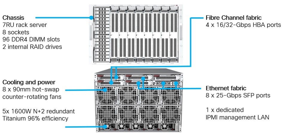
The high-performance eight-socket Cisco UCS C890 M5 Rack Server is based on the 2nd Gen Intel Xeon Scalable processors and extends the Cisco UCS platform. It is well suited for mission-critical business scenarios such as medium- to large-size SAP HANA database management systems including high availability and secure multitenancy. It works with virtualized and nonvirtualized applications to increase performance, flexibility, and administrator productivity.
The 7RU server (Figure 2. ) has eight slots for computing modules and can house a pool of future I/O resources that may include graphics processing unit (GPU) accelerators, disk storage, and Intel Optane PMem. The mixed memory configuration of DDR4 modules and Intel Optane PMem in App Direct mode supports up to 36 TB of main memory.
At the top rear of the server are six PCIe slots with one expansion slot available for customer specific extension. Eight 25-Gbps Small Form-Factor Pluggable (SFP) Ethernet uplink ports carry all network traffic to a pair of Cisco Nexus 9000 Series Switches. Four 16 or 32-Gbps Fibre Channel host bus adapter (HBA) ports connect the server to a pair of Cisco MDS 9000 Series Multilayer Switches and to the All-Flash Non-Volatile Memory Express (NVMe) FlashArray//X. Unique to Fibre Channel technology is its deep support ecosystem, making it well-suited for large-scale, easy-to-manage FlashStack deployments.
Equipped with internal RAID 1 small-form-factor (SFF) SAS boot drives, the storage- and I/O-optimized enterprise-class rack server delivers industry-leading performance for both virtualized and bare-metal installations. The server offers exceptional flexibility in its integration into the data center landscape with its additional capabilities for SAN boot, boot from LAN or its build in multiprotocol remote boot Mellanox FlexBoot technology.
Cisco UCS C890 M5 Rack Server
Mellanox ConnectX-4 network controller
The Mellanox-based super I/O module (SIOM) and two network interface cards (NICs) provide exceptional high performance for the most demanding data centers, public and private clouds, and SAP HANA applications. The 25 Gigabit Ethernet NIC is fully backward compatible with 10 Gigabit Ethernet networks and supports bandwidth demands for both virtualized infrastructure in the data center and cloud deployments.
To support the various SAP HANA scenarios and to eliminate single points of failure, two additional 25-Gbps dual-port SFP28 network controller cards or, optionally, 40 Gigabit Ethernet dual-port SFP28 network controller cards extend the capabilities of the baseline configuration of the Cisco UCS C890 M5 server.
A single 25 Gigabit Ethernet NIC is typically sufficient to run an SAP HANA database on a single host. The situation for a distributed system, however, is more complex, with multiple hosts located at a primary site having one or more secondary sites and supporting a distributed multiple-terabyte database with full fault and disaster recovery. For this purpose, SAP defines different types of network communication channels, called zones, to support the different SAP HANA scenarios and setups. Detailed information about the various network zones is available in the SAP HANA network requirements document.
Broadcom LPe32002 Fibre Channel HBA
The dual-port Broadcom LPe32002 16- or 32-Gbps Fibre Channel HBA addresses the demanding performance, reliability, and management requirements of modern networked storage systems that use high-performance and low-latency solid-state disks (SSDs) or hard-disk drive (HDD) arrays.
The sixth generation of the Emulex Fibre Channel HBAs with dynamic multicore architecture offers higher performance and more efficient port utilization than other HBAs by applying all application-specific integrated circuit (ASIC) resources to any port as the port requires them.
Intelligent Platform Management Interface
The IPMI console management interface provides remote access for multiple users and allows you to monitor system health and to manage server events remotely.
Installed on the motherboard, IPMI operates independently from the operating system and allows users to access, monitor, diagnose, and manage the server through console redirection.
These are some of the main elements that IPMI manages:
● Baseboard management controller (BMC) built-in IPMI firmware
● Remote server power control
● Remote serial-over-LAN (SOL) technology (text console)
● BIOS and firmware upgrade processes
● Hardware monitoring
● Event log support
Cisco Intersight platform
The Cisco Intersight solution, Cisco’s new systems management platform, delivers intuitive computing through cloud-powered intelligence. This modular platform offers a more intelligent level of management and enables IT organizations to analyze, simplify, and automate their IT environments in ways that were not possible with prior generations of tools. This capability empowers organizations to achieve significant savings in total cost of ownership (TCO) and to deliver applications faster to support new business initiatives.
The Cisco Intersight platform uses a unified open API design that natively integrates with third-party platforms and tools.
Cisco Intersight delivers unique capabilities such as the following:
● Integration with the Cisco Technical Assistance Center (TAC) for support and case management
● Proactive, actionable intelligence for issues and support based on telemetry data
● Compliance check through integration with the Cisco Hardware Compatibility List (HCL)
Cisco Intersight functions for the Cisco UCS C890 M5 server will become available through software updates in the future and will not require any hardware adjustments to adopt.
For more information about the Cisco Intersight platform, see the Cisco Intersight Services SaaS systems management platform.
Cisco Nexus 9000 Series Switches
Cisco Nexus 9000 Series Switches offer both modular and fixed 1-,10-,25-,40- and 100 Gigabit Ethernet switch configurations with scalability of up to 60 Tbps of nonblocking performance with less than 5 microseconds of latency. It offers wire-speed VXLAN gateway, bridging, and routing support.
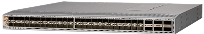
Cisco Nexus 93180YC-FX3 Switch
The Cisco Nexus 9000 Series Switch used in this design is the Cisco Nexus 93180YC-FX3 (Figure 3. ) operating in NX-OS standalone mode. Cisco NX-OS is a datacenter operating system designed for performance, resiliency, scalability, manageability, and programmability at its foundation. It provides a robust and comprehensive feature set that meets the demanding requirements of virtualization and automation in present and future datacenters.
The 1RU Cisco Nexus 93180YC-FX3 Switch supports 3.6 Tbps of bandwidth and 1.2 billion packets per second (PPS). The 48 downlink ports on the 93180YC-FX3 can support 1-,10- and 25 Gigabit Ethernet, offering deployment flexibility and investment protection. You can configure the 6 uplink ports as 40- or 100 Gigabit Ethernet, offering flexible migration options.
For more information, see the Cisco Nexus 9300-FX3 Series data sheet.
Cisco MDS 9100 Series Multilayer Fabric Switch
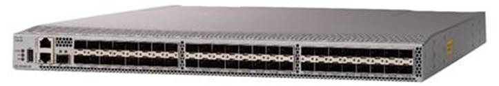
The Cisco MDS 9148T 32-Gbps multilayer fabric switch is the next generation of the highly reliable, flexible, and low-cost Cisco MDS 9100 Series Multilayer Fabric Switches (Figure 4). It combines high-speed Fibre Channel connectivity for All-Flash arrays with exceptional flexibility and cost effectiveness. This powerful, compact 1RU switch scales from 24 to 48 line-rate 32-Gbps Fibre Channel ports.
Cisco MDS 9148T Fibre Channel Switch
The Cisco MDS 9148T delivers advanced storage networking features and functions with ease of management and compatibility with the entire Cisco MDS 9000 Family portfolio for reliable end-to-end connectivity. This switch also offers state-of-the-art SAN analytics and telemetry capabilities that are built into this next-generation hardware platform. This new state-of-the-art technology couples the next-generation port ASIC with a fully dedicated network processing unit designed to complete analytics calculations in real time.
For more information, see the Cisco MDS 9148T 32-Gbps 48-Port Fibre Channel Switch data sheet.
Cisco Data Center Network Manager SAN
Use the Cisco Data Center Network Manager (DCNM)-SAN to monitor, configure, and analyze Cisco 32-Gbps Fibre Channel fabrics and show information about the Cisco Nexus switching fabric. Cisco DCNM-SAN is deployed as a virtual appliance from an Open Virtualization Archive (OVA) file and is managed through a web browser. When you add the Cisco MDS and Nexus switches with the appropriate credentials and licensing, you can begin monitoring the SAN and Ethernet fabrics. Also, you can add, modify, and delete virtual SANs (VSANs), device aliases, zones, and zone sets using the Cisco DCNM point-and-click interface. Configure the Cisco MDS switches from within Cisco Data Center Device Manager. Add SAN analytics to Cisco MDS switches to gain insight into the fabric to monitor, analyze, identify, and troubleshoot performance problems.
Cisco DCNM integration with Cisco Intersight platform
The Cisco Network Insights Base (Cisco NI Base) application provides useful Cisco TAC Assist functions. It provides a way for Cisco customers to collect technical support across multiple devices and upload that technical support information to the Cisco cloud. The Cisco NI Base application collects the CPU, device name, device product ID, serial number, version, memory, device type, and disk-use information for the nodes in the fabric. The Cisco NI Base application is connected to the Cisco Intersight cloud portal through a device connector that is embedded in the management controller of the Cisco DCNM platform. The device connector provides a secure way for the connected Cisco DCNM to send and receive information from the Cisco Intersight portal by using a secure Internet connection.
Pure Storage FlashArray//X
The Pure Storage FlashArray product family delivers software-defined all-flash power and reliability for businesses of every size. FlashArray is all-flash enterprise storage that is up to 10 times faster, more space and power efficient, more reliable, and far simpler than other available solutions. The 100 percent NVMe enterprise-class all-flash FlashArray//X delivers a higher performance tier for mission-critical databases, top-of-rack flash deployments, and tier-1 application consolidation. The //X, at 1PB in a 3RU form factor, with a 100-microsecond latency range, and gigabytes of bandwidth, delivers an exceptional performance density. FlashArray//X is well-suited for cost-effectively consolidating everything on flash storage, including accelerating a single database, scaling virtual desktop environments, and powering an all-flash cloud.
For more information about SAP HANA certified FlashArray//X R3 arrays, see the SAP certified and supported SAP HANA hardware directory.
Purity for FlashArray
Purity//X for FlashArray implements advanced data reduction, storage management, and flash management features, enabling your organization to experience tier-1 data services for all workloads. Purity software provides proven 99.9999-percent availability over 2 years, completely nondisruptive operations, twice the data reduction of competing solutions, and the power and efficiency of DirectFlash. Purity also includes enterprise-class data security, comprehensive data-protection options, and complete business continuity with an ActiveCluster multi-site stretch cluster. All these features are included with every Pure Storage array.
SAP HANA TDI
The SAP HANA in-memory database combines transactional and analytical SAP workloads and hereby takes advantage of low-cost main memory and the data-processing capabilities of multicore processors, and faster data access.
SAP provides an overview of the six phases of SAP HANA TDI, describing the hardware and software requirements for the entire stack. For more information, see the SAP HANA Tailored Data Center Integration–Overview. The enhanced sizing approach allows consolidation of the storage requirements for the whole SAP landscape, including SAP application servers, in a single, central, high-performance enterprise storage array.
Workload based sizing supports easy integration of the Cisco ICS C890 M5 Rack Server into new or current FlashStack deployments with the advantages of an integrated computing and storage stack whether as a single-host (scale up) or multiple-host (scale out) SAP HANA environment.
SAP application monitoring with Cisco AppDynamics
Cisco AppDynamics® is an application performance monitoring (APM) platform that helps you understand and optimize the performance of your business, from its software to its infrastructure.
The AppDynamics APM platform enables you to monitor and manage your entire application-delivery ecosystem, from the mobile app or browser client request through your network, back-end databases, and application servers and more. AppDynamics APM gives you a single view across your application landscape, letting you quickly navigate from the global perspective of your distributed application down to the call graphs and exception reports generated on individual hosts.
AppDynamics has an agent-based architecture running on the SAP application server. After the agents are installed, you see a dynamic flow map or topography of your application. AppDynamics uses the concept of traffic lights to indicate the health of your application (green indicates that the application is good, yellow indicates that it is slow, and red indicates potential problems), with dynamic baselining. AppDynamics measures application performance based on business transactions, which essentially are the main functions of the application. When the application deviates from the baseline, AppDynamics captures and provides deeper diagnostic information to help you troubleshoot more proactively and reduce the mean time to repair (MTTR).
More information is available online at https://docs.appdynamics.com/display/SAP/SAP+Monitoring+Using+AppDynamics.
Cisco Customer Experience Services: Cisco Solution Support
Cisco Solution Support includes both support for Cisco products and support for overall solutions, resolving complex issues in multivendor environments on average 43 percent more quickly than with product support alone. Cisco Solution Support is a critical element in data center administration to help rapidly resolve any problem encountered while maintaining performance, reliability, and return on investment (ROI). This service centralizes support across your multivendor Cisco environment for both our products and solution partner products deployed in your ecosystem. Whether you experience a problem with a Cisco or a solution partner product, just call us. Our experts are the primary point of contact and own the case from the first call to resolution.
For more information, see https://www.cisco.com/c/m/en_us/customer-experience/support/solution-support.html.
The Cisco UCS C890 M5 Rack Server is well suited for any SAP workload, bare-metal or virtualized, and manages SAP HANA databases up to their limit of 24 TB of addressable main memory. In addition to the default reliability, availability, and serviceability (RAS) features, the configuration design of the server includes redundant boot storage and network connectivity. Hardware and software requirements to run SAP HANA systems are defined by SAP. FlashStack uses guidelines provided by SAP, Cisco, and the solution partners involved.
Solution requirements
Several hardware and software requirements defined by SAP must be fulfilled before you setup and install any SAP HANA server. This section describes the solution requirements and design details.
CPU architecture
The eight-socket Cisco UCS C890 M5 Rack server is available with the 2nd gen Intel Xeon Scalable Platinum 8276 or 8280L processors with 28 cores per CPU socket each, or 224 cores total.
The smaller Platinum 8276 processors address a maximum memory size of 6 TB of main memory, and the recommended Platinum 8280L processor addresses all memory configurations listed in Table 1.
Memory platform support
Because of the SAP defined memory per socket ratio a fully DDR4 DRAM populated Cisco UCS C890 M5 Rack Server is certified for SAP HANA 2.0 with up to:
● 6 TB for SAP NetWeaver Business Warehouse (BWoH/BW4H) and DataMart
● 12 TB for SAP Business Suite (SoH/S4H)
Intel Optane PMem modules are supported with recent Linux distributions and SAP HANA 2.0. In App Direct mode, the persistent memory modules appear as byte-addressable memory resources that are controlled by SAP HANA.
The use of Intel Optane PMem requires a homogeneous, symmetrical assembly of DRAM and PMem modules with maximum utilization of all memory channels per processor. Different-sized Intel Optane PMem and DDR4 DIMMs can be used together as long as supported ratios are main-tained.
Various capacity ratios between PMem and DRAM memory modules are supported which heavily dependent on the data model and data distribution. A correct SAP sizing exercise is strongly recommended before considering Intel Optane PMem for SAP HANA.
FAQ: SAP HANA Persistent Memory provides more information if you are interested in using persistent memory in SAP HANA environments.
Table 1. Cisco UCS C890 M5 Rack server Memory Configuration Overview
|
|
|
Quantity |
DDR4 capacity |
PMem capacity |
Usable capacity |
| CPU specifications |
Intel Xeon Platinum 8280L processor |
8 |
|
|
|
| Memory Configurations |
64 GB of DDR4 128 GB of DDR4 256 GB of DDR4 |
96 96 96 |
6 TB 12 TB 24 TB |
- - - |
6 TB 12 TB 24 TB* |
|
|
64 GB of DDR4 and 128 GB of PMem 128 GB of DDR4 and 128 GB of PMem 64 GB of DDR4 and 256 GB of PMem 128 GB of DDR4 and 256 GB of PMem 256 GB of DDR4 and 256 GB of PMem 128 GB of DDR4 and 512 GB of PMem 256 GB if DDR4 and 512 GB of PMem |
48 and 48 |
3 TB 6 TB 3 TB 6 TB 12 TB 6 TB 12 TB |
6 TB 6 TB 12 TB 12 TB 12 TB 24 TB 24 TB |
9 TB 12 TB 15 TB* 18 TB* 24 TB* 30 TB* 36 TB* |
| * In bare-metal installations, SAP HANA supports a maximum of 12 TB (24 TB with Intel Optane PMem). In a virtualized environment, SAP HANA supports a maximum of 6 TB per single virtual machine. |
|||||
Network requirements
An SAP HANA data center deployment can range from a database running on a single host to a complex distributed system. Distributed systems can be complex, with multiple hosts located at a primary site having one or more secondary sites and supporting a distributed multiple-terabyte database with full fault and disaster recovery.
SAP recommends separating the network into different zones for client, storage, and host-to-host communication. Refer to the document SAP HANA Network Requirements for more information and sizing recommendations.
The network interfaces of the Cisco UCS C890 M5 server provide 25 Gbps network connectivity are sufficient to meet the SAP HANA network requirements.
The Pure Storage FlashArray//X connects to a pair of Cisco MDS 9148T Fibre Channel Switches and to the Cisco UCS C890 M5 Rack Server HBA with either 16 or 32-Gbps port speed, which meets the minimum requirement of an 8-Gbps port speed.
Operating system
This Cisco UCS C890 M5 Rack Server is certified for Red Hat Enterprise Linux (RHEL) 8 for SAP Solutions and SUSE Linux Enterprise Server (SLES) 15 for SAP Applications. The Linux operating systems fully supports the Intel Optane PMem technology.
To evaluate compatibility between Linux operating system release and SAP HANA platform releases, refer to SAP Note 2235581: SAP HANA: Supported Operating Systems.
SAP HANA single-node system (scale up)
The SAP HANA scale up solution is the simplest installation type. In general, this solution provides the best SAP HANA performance. All data and processes are located on the same server and do not require additional network considerations for internode communication, for example. This solution requires one server with dedicated volumes for Linux and SAP HANA on the FlashArray//X.
FlashStack scales with the size and number of available ports of the Cisco MDS 9000 Family multilayer SAN switches and the Cisco Nexus network switches, and in addition with the capacity and storage controller capabilities of the FlashArray//X. The certification scenarios and their limitations are documented in the SAP Certified and Supported SAP HANA Hardware directory.
SAP HANA multi-node system (scale out)
An SAP HANA scale up installation with a high-performance Cisco UCS C890 M5 server is the preferred deployment for large SAP HANA databases. Nevertheless, you will need to distribute the SAP HANA database to multiple nodes if the amount of main memory of a single node is not sufficient to keep the SAP HANA database in memory. Multiple independent servers are combined to form one SAP HANA system, distributing the load among multiple servers.
In a distributed system, typically each index server is assigned to its own host to achieve the best performance. You can assign different tables to different hosts (database partitioning), or you can split a single table across hosts (table partitioning). SAP HANA comes with an integrated high-availability option, configuring one single server as a standby host.
To access the shared SAP HANA binaries, Network File System (NFS) storage is required independent from the storage connectivity of the SAP HANA log and data volumes. In the event of a failover to the standby host, the SAP HANA Storage Connector API manages the remapping of the logical volumes. Redundant connectivity to the corporate network over LAN (Ethernet) and to the storage over SAN (Fibre Channel) always must be configured.
The Cisco UCS C890 M5 Rack Server is certified for up to four active SAP HANA worker nodes whether for SAP Suite for HANA or SAP Business Warehouse for HANA. More nodes usually are supported by SAP after an additional validation.
SAP HANA TDI storage size requirements
If no application-specific sizing program data is available, the recommended size for the SAP HANA volumes is directly related to the total memory required for the system. Additional information is available from the SAP HANA Storage Requirements white paper.
Each SAP HANA TDI worker node has the following recommended volume sizes:
● /usr/sap ≥ 52 GB
● /hana/data = 1 x memory
● /hana/log = 512 GB
For an SAP HANA scale up system, the disk space recommendation for the SAP HANA shared volume is:
● /hana/shared = 1024 GB
For up to four worker nodes in an SAP HANA scale out system the disk space recommendation for the NFS shared SAP HANA shared volume is:
● /hana/shared = 1 x memory
Virtualized SAP HANA
SAP HANA database bare-metal installations can run along with virtualized SAP application workloads, which are common in the data center. Additional rules and limitations apply when the SAP HANA database is virtualized, such as rules related to the number of virtual CPUs (vCPUs) and memory limits. SAP Note 2652670 provides links and information you can refer to when installing the SAP HANA platform in a virtual environment using VMware vSphere virtual machines.
High availability
Multiple approaches are available to increase the availability and resiliency of SAP HANA running on the Cisco UCS C890 M5 server within FlashStack, to protect against interruptions and prevent outages from occurring in the first place. Here are just a few hardware-based configuration recommendations to eliminate any single point of failure:
● FlashArray//X with proven 99.9999 percent availability
● Dual network cards with active-passive or Link Aggregation Control Protocol (LACP) network bond configuration
● Redundant and hot-swappable power supplies and fans
● Redundant data paths and dual controllers of FlashArray//X
● Purity ActiveCluster™ synchronous replication and automatic transparent failover
Software-based recommendations include SAP HANA embedded functions such as the use of an SAP HANA standby host in a scale out scenario or SAP HANA system replication to another host, ideally part of a Linux cluster setup, which can reduce downtimes to minutes. Designs that include redundancy entail trade-offs between risk and cost, so choose the right balance for your data center operations requirements.
Most IT emergencies are caused by hardware failures and human errors, and a disaster-recovery strategy is recommended as well. An SAP HANA certified software solution such as Veeam Backup & Replication integrates seamlessly with native SAP HANA backint backups and provides disaster-recovery support. Other software-based solutions are Commvault and Cohesity Data Platform.
This section describes the configuration steps for installing and integrating the Cisco UCS C890 M5 Rack Server into an existing FlashStack for SAP HANA TDI environment. For more information, see the FlashStack for SAP HANA TDI deployment guide.
Naming conventions
This document uses the conventions listed here for commands that you enter at the command-line interface (CLI).
Commands you enter at a CLI prompt are shown like this:
hostname# hostname
Angle brackets (<>) indicate a mandatory character string that you need to enter, such as a variable pertinent to the customer environment or a password.
hostname# ip add <ip_address/mask> dev <interface>
For example, to assign 192.168.1.200/255.255.255.0 to network interface eth0, enter this command:
hostname# ip add 192.168.1.200/255.255.255.0 dev eth0
Cisco Nexus switch configuration
The network cards support LACP for Ethernet, which controls the way how physical ports are bundled together to form one logical channel. Combine one link from the four-port SIOM card and one link from one of the dual-port Ethernet cards into a port channel for higher availability.
During the Linux installation, configure a network bond using these two links in LACP or 802.3ad mode, depending on the Linux distribution.
Cisco MDS switch configuration
The configuration in the section assumes the use of a single server. Multiple servers can be configured at the same time. To distinguish the different HBA port names, start the server and enter the Broadcom Emulex configuration utility to confirm the HBA port names for the specific server.
If the server is connected to different ports or VSANs, configure the switches accordingly, following the guidelines in this section.
Cisco MDS smart zoning
The traditional zoning method allows each device in a zone to communicate with every other device in the zone. Smart zoning allows the configuration of initiator-target pairs using fewer hardware resources than were previously required. The device-type information for each device in a smart zone is automatically populated from the Fibre Channel name server (FCNS) database.
Create device aliases for the Fibre Channel zoning
Configure device aliases and zones for the primary boot paths:
1. Open Secure Shell (SSH) for to MDS-A and run the following commands:
MDS-A # show flogi database
--------------------------------------------------------------------------------
INTERFACE VSAN FCID PORT NAME NODE NAME
--------------------------------------------------------------------------------
fc1/7 1 0x880160 10:00:00:10:9b:ad:12:34 20:00:00:10:9b:ad:12:34
fc1/8 1 0x880180 10:00:00:10:9b:ad:24:58 20:00:00:10:9b:ad:24:58
fc1/29 10 0x880060 52:4a:93:78:09:e6:be:01 52:4a:93:78:09:e6:be:01
[Pure-CT0-FC1]
fc1/30 10 0x880020 52:4a:93:78:09:e6:be:11 52:4a:93:78:09:e6:be:11
[Pure-CT1-FC1]
fc1/31 10 0x880040 52:4a:93:78:09:e6:be:03 52:4a:93:78:09:e6:be:03
[Pure-CT0-FC3]
fc1/32 10 0x880000 52:4a:93:78:09:e6:be:13 52:4a:93:78:09:e6:be:13
[Pure-CT1-FC3]
port-channel10 10 0x880080 24:0a:00:3a:9c:3a:54:40 20:0a:00:3a:9c:3a:54:41
Total number of flogi = 8.
2. Create a device alias for the Cisco UCS C890 M5 HBA ports using the Word Wide Name (WWN) displayed under the node name, typically starting with 20:00:00:
MDS-A(config)# vsan database
MDS-A(config-vsan-db)# vsan 10 interface fc1/7
MDS-A(config-vsan-db)# vsan 10 interface fc1/8
MDS-A(config-vsan-db)# device-alias database
MDS-A(config-device-alias-db)#
device-alias name C890-node01-hba-1a pwwn 20:00:00:10:9b:ad:12:34
device-alias name C890-node01-hba-2a pwwn 20:00:00:10:9b:ad:24:58
MDS-A(config-device-alias-db)# exit
MDS-A(config)# device-alias commit
3. Open SSH for MDS-B and run the following commands:
MDS-B# show flogi database
--------------------------------------------------------------------------------
INTERFACE VSAN FCID PORT NAME NODE NAME
--------------------------------------------------------------------------------
fc1/7 1 0xae0160 10:00:00:10:9b:ad:12:33 20:00:00:10:9b:ad:12:33
fc1/8 1 0xae0180 10:00:00:10:9b:ad:24:57 20:00:00:10:9b:ad:24:57
fc1/29 20 0xae0060 52:4a:93:78:09:e6:be:00 52:4a:93:78:09:e6:be:00
[Pure-CT0-FC0]
fc1/30 20 0xae0040 52:4a:93:78:09:e6:be:10 52:4a:93:78:09:e6:be:10
[Pure-CT1-FC0]
fc1/31 20 0xae0020 52:4a:93:78:09:e6:be:02 52:4a:93:78:09:e6:be:02
[Pure-CT0-FC2]
fc1/32 20 0xae0000 52:4a:93:78:09:e6:be:12 52:4a:93:78:09:e6:be:12
[Pure-CT1-FC2]
port-channel20 20 0xae0080 24:14:00:3a:9c:3a:53:20 20:14:00:3a:9c:3a:53:21
Total number of flogi = 8.
4. Create a device alias for the Cisco UCS C890 M5 HBA ports using the WWN displayed under the node name, typically starting with 20:00:00:
MDS-B(config)# vsan database
MDS-B(config-vsan-db)# vsan 20 interface fc1/7
MDS-B(config-vsan-db)# vsan 20 interface fc1/8
MDS-B(config-vsan-db)# device-alias database
MDS-B(config-device-alias-db)#
device-alias name C890-node01-hba-1b pwwn 20:00:00:10:9b:ad:12:33
device-alias name C890-node01-hba-2b pwwn 20:00:00:10:9b:ad:24:57
MDS-B(config-device-alias-db)# exit
MDS-B(config)# device-alias commit
5. Create a new zone on each Cisco MDS switch. In an SAP HANA scale out scenario add each interface of the worker nodes to the same, single zone to enable the SAP HANA failover mechanism:
MDS-A(config)# zone name HANA-C890-SU-a vsan 10
MDS-A(config-zone)# member device-alias Pure-CT0.FC1
MDS-A(config-zone)# member device-alias Pure-CT1.FC1
MDS-A(config-zone)# member device-alias Pure-CT0.FC3
MDS-A(config-zone)# member device-alias Pure-CT1.FC3
MDS-A(config-zone)# member device-alias C890-node01-hba-1a
MDS-A(config-zone)# member device-alias C890-node01-hba-2a
MDS-A(config-zone)# exit
MDS-B(config)# zone name HANA-C890-SU-b vsan 20
MDS-B(config-zone)# member device-alias Pure-CT0.FC1
MDS-B(config-zone)# member device-alias Pure-CT1.FC1
MDS-B(config-zone)# member device-alias Pure-CT0.FC3
MDS-B(config-zone)# member device-alias Pure-CT1.FC3
MDS-B(config-zone)# member device-alias C890-node01-hba-1b
MDS-B(config-zone)# member device-alias C890-node01-hba-2b
MDS-B(config-zone)# exit
6. On each Cisco MDS switch, add the new member to the zone set:
MDS-A(config)# zoneset name HANA-Nodes-A vsan 10
MDS-A(config-zoneset)# member HANA-C890-SU-a
MDS-A(config-zoneset)# exit
MDS-B(config)# zoneset name HANA-Nodes-B vsan 20
MDS-B(config-zoneset)# member HANA-C890-SU-b
MDS-B(config-zoneset)# exit
7. Activate the zone set on each Cisco MDS switch:
MDS-A(config)# zoneset activate name HANA-Nodes-A vsan 10
MDS-A(config)# exit
MDS-B(config)# zoneset activate name HANA-Nodes-B vsan 20
MDS-B(config)# exit
8. Save the configuration to persist it:
MDS-[A|B] # copy run start
Pure Storage FlashArray//X configuration
The virtual Purity//FA hosts organize the NVMe Qualified Names (NQNs) and the Fibre Channel WWNs that identify the host computer initiators. Create hosts to access volumes on the array. Configure a new host on the FlashArray//X. Keep the server powered on to use the host auto-discovery feature of the FlashArray//X.
For an SAP HANA scale out scenario, create a new host for each worker node and set up the Fibre Channel interfaces. Add the SAN boot logical unit number (LUN) using LUN ID 1. Then create a new host group and add the hosts that belong to the SAP HANA scale out setup to the host group. Connect all SAP HANA data and log LUNs to the host group instead of having individual host configurations to avoid potential LUN ID crossovers for the data and log LUNs. Create a single new HANA shared LUN and contact Pure Storage Technical Support to setup NFS access to the HANA shared volume for the distributed environment.
The following example configures a SAP HANA scale up host with 6TB main memory using SAN boot. Adapt the SAP HANA storage requirements according to your needs.
1. Log in to the Purity//FA dashboard at http://<var_purecluster_ip>.
2. Select Storage in the navigation pane.
3. Select Hosts in the work pane. To create a new host, click the + sign on the right.
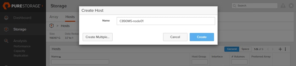
4. Enter a host name and click Create.
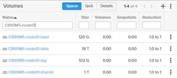
5. Select Volumes in the navigation pane.
6. In the Volumes work pane click the + sign to create a new volume.
7. Provide a volume name and choose the appropriate volume size.

8. Click Create.
9. Repeat step 6 to 8 and create a volume for SAP HANA data, log and HANA shared.
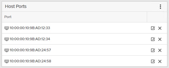
10. Select Hosts in the navigation pane.
11. Select the host C890-node01 created previously in the Hosts work pane.
12. In the Host Ports pane, click the settings button and select Configure WWNs.
13. Select and add the Fibre Channel WWNs (listed in the port name column when you run the show flogi database command on the Cisco MDS switch, as shown earlier.
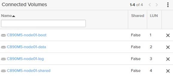
14. In the Connected Volumes pane, click the settings button and choose to connect from the drop-down menu.
15. Select just the volume C890M5-node01-boot, specify LUN ID 1, and click Connect.
16. Repeat step 15 and select the SAP HANA data, log, and HANA shared volumes. Click Connect.
Cisco UCS C890 M5 Rack Server configuration
This section assumes that the cabling is complete and the previous configuration steps have been completed.
BIOS configuration
Set up the IPMI LAN configuration first so that you can continue the configuration from the remote console.
Connect to the KVM console
1. Connect the keyboard, video, and mouse (KVM) cable from the accessory box to a laptop for the initial BIOS and IPMI configuration.
2. Press the power button located at the top right corner on the front side of the server.
3. When the Cisco logo appears, press <DEL> to enter the AMI BIOS setup utility.
4. Set the system date and system time on the main screen of the BIOS.
5. Change to the IPMI top menu and use the arrow keys to select the BMC Network Configuration sub menu.
6. Update the IPMI LAN configuration and provide an IP address, subnet mask, and gateway IP address.
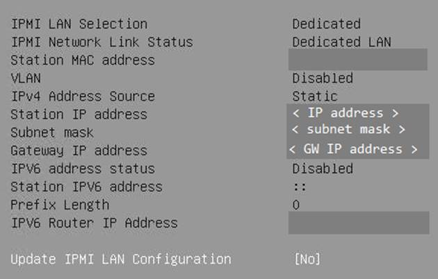
7. Move to the Save & Exit top menu and save the changes before you reset the server
![]()
8. When the Cisco logo appears, press <DEL> to enter the AMI BIOS setup utility again.
IPMI Console Management
Disconnect the KVM cable and connect to the IPMI LAN IP address with your preferred browser.
1. Log in with the user ADMIN using the unique password which comes with the server.
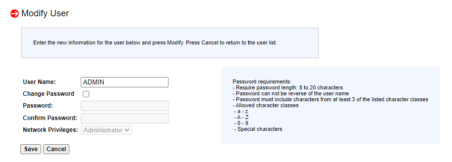
2. To modify the initial password, choose Configuration > Users.
3. Select the row with the ADMIN user and click the Modify User button to change the initial password.
4. Choose Remote Control > Remote Console
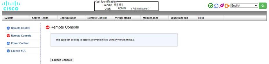
5. Click the Launch Console button to access the remote console.
The remote console opens in a new window displaying the AMI BIOS setup utility
Advanced menu (CPU configuration)
1. Use the arrow keys to select the CPU Configuration sub menu.
2. For the bare-metal installation disable Intel Virtualization Technology.
![]()
3. Select Advanced Power Management Configuration at the bottom of the processor configuration page.
4. Change Power Technology to Custom.
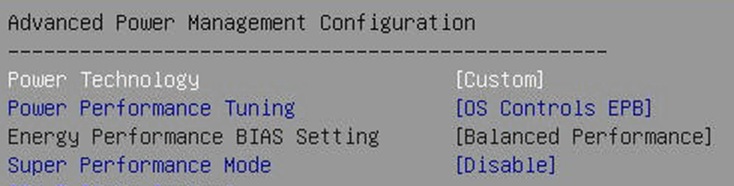
5. Select CPU C State Control and disable Autonomous Core C-State and CPU C6 report.

6. Select Package C State Control and change the Package C State value to C0/C1 state.

Advanced menu (Memory RAS configuration)
Modern servers, including Cisco UCS M5 servers, provide increased memory capacities which run at higher bandwidths and lower voltages. These trends, along with higher application memory demands and advanced multicore processors, contribute to an increased probability of memory errors.
Fundamental error-correcting code (ECC) capabilities and scrub protocols were historically successful at handling and mitigating memory errors. As memory and processor technologies advance, RAS features must evolve to address new challenges. You can improve the server resilience with the adaptive double device data correction (ADDDC sparing) feature, which mitigates correctable memory errors.
1. Use the arrow keys to select the Chipset Configuration sub menu.
2. Continue with North Bridge and Memory Configuration.
3. Keep all values and select Memory RAS Configuration at the bottom of the screen.
4. Enable ADDDC Sparing
![]()
Advanced menu (PCIe/PCI/PnP configuration)
In the default configuration, the PCI Devices Option Rom setting values are set to Legacy. Configuration utilities for the add-on cards are available when you press a key combination such as <Ctrl>-<R> for the MegaRAID cards during initialization of the card itself. Changing the BIOS settings to EFI will enable you to access the configuration utilities directly from the BIOS after the next reboot.
1. Use the arrow keys to select the PCIe/PCI/PnP Configuration sub menu.
2. Change the PCI Devices Option Rom settings from Legacy to EFI.
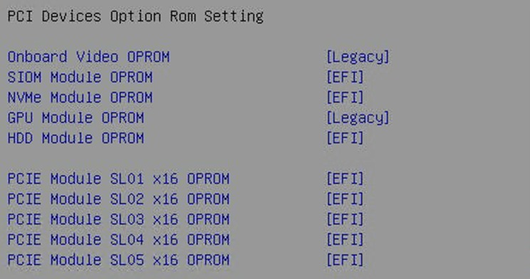
3. Optionally, select the network stack configuration to disable PXE and HTTP boot support if this is not required.

Boot menu (Boot mode configuration)
Switch to the Boot screen in the top menu. Confirm the entry for boot mode select is UEFI.
![]()
Boot menu (Save & Exit)
Save all changes and reset the server to activate the changes.
![]()
After the system initialization process, the Cisco logo appears. Press <DEL> to enter the AMI BIOS setup utility again.
Emulex LightPulse Fibre Channel configuration
Enable SAN boot and configure the four ports of the Emulex LPe320002-M2 accordingly.
1. Use the arrow keys to select the Advanced menu tab.
2. Use the arrow keys to scroll to the first Emulex LightPulse LPe32002-M2 2-Port 32Gb Ch – FC entry and press the return key.
3. Change the entry Set Boot from SAN to enable
![]()
4. Scan for fibre channel devices to discover all targets.
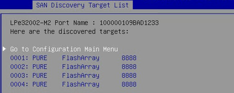
5. Press Enter to return to the configuration main menu.
6. Select Add Boot Device.
7. Select the 0001: PURE FlashArray entry and press Enter.
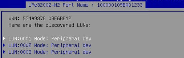
8. Select the LUN with ID 0001 and press Enter.
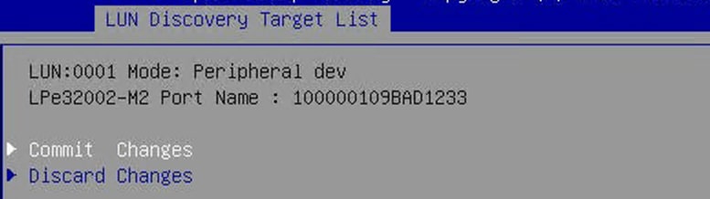
9. Commit the change and press <Esc> to return to the SAN Discovery Target List screen.
10. Repeat steps 7 to 9 for target 002, 003 and 004 and return to the configuration main menu.
11. Select the menu item Delete Boot Device to confirm that all four paths have been added.
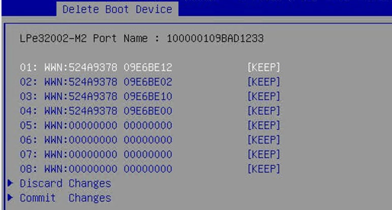
12. Press <Esc> twice to return to the advanced menu.
13. Repeat step 2 to 12 for the next three Emulex LP Fibre Channel ports.
Intel Optane persistent memory configuration
If the Cisco UCS C890 M5 server is not equipped with Intel Optane PMem modules the BIOS menu entry is hidden.
1. From the Advanced screen select Intel Optane DC Persistent Memory Configuration.
2. Confirm all 48 DIMMs have been detected and are healthy
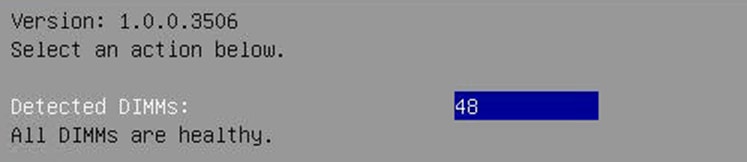
For SAP HANA bare-metal installations, no further BIOS configuration is required. The Intel Optane PMem modules will be managed using the management utilities from the Linux command line. Return to the main screen and keep the server in the AMI BIOS setup utility.
SAP HANA with Intel Optane PMem on VMware vSphere configuration
For SAP HANA VMware-based installations, the Intel Optane PMem modules require initial configuration in the BIOS so that VMware ESXi can detect the Intel Optane PMem namespaces properly. Further configuration in VMware vCenter (VMware knowledge base article 78094) and configuration changes using the management utilities from the Linux command line within the virtual machine are required. Additional information is available from SAP note 2913410: SAP HANA on VMware vSphere with Persistent Memory.
For the initial configuration of the Intel Optane PMem modules for VMware configurations follow these steps:
1. On the Advanced screen select Intel Optane DC Persistent Memory Configuration.
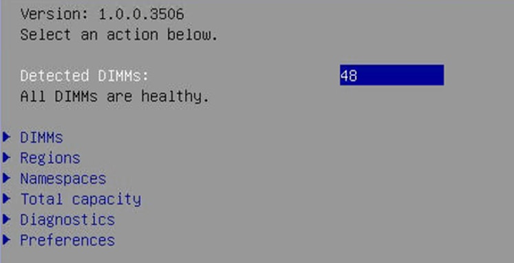
2. Select Regions and scroll to the end of the screen. Select Create goal config and press Enter.
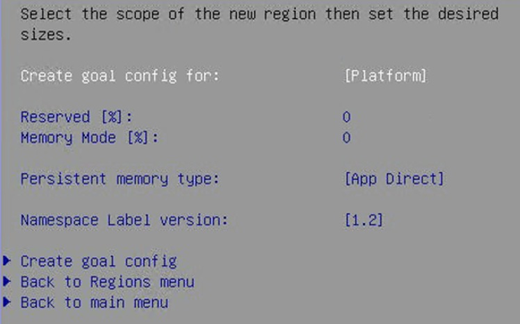
3. Keep the defaults to create a goal for App Direct mode. Select Create goal config and press Enter.
4. Save the changes and reset the server to initialize the Intel Optane PMem modules.
5. When the Cisco logo appears, press <DEL> to enter the AMI BIOS setup utility.
6. Move to the Advanced screen and select Intel Optane DC Persistent Memory Configuration.
7. Select Namespaces and then Create namespace.
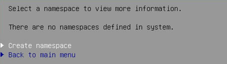
8. Select Name and press Enter to provide a name for the new namespace. Select the region ID accordingly. For example, use namespace1.0 for Region ID 0x0001.
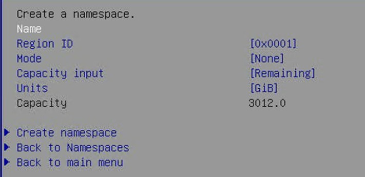
9. Keep the mode set to None, which creates a namespace in raw mode.
10. Select Create namespace.
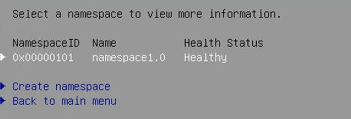
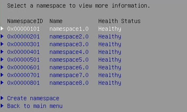
11. Repeat step 7 to 9 and create a namespace for each of the eight region IDs. The final screen can look like this:
12. Select Save from the Save & Exit top menu and press Enter to save the changes.
13. Mount the ESXi ISO installation image to proceed with the VMware installation after the next reboot.
This section describes the procedure for installing the Linux operating system, including steps to customize the operating system to meet the SAP HANA requirements. The Fibre Channel HBAs are configured for SAN boot using a storage system LUN instead of the internal hard disks.
If you plan to install Red Hat Enterprise Linux for SAP Solutions, skip the next section, which discusses the installation of SUSE Linux Enterprise Server for SAP Applications.
SUSE Linux Enterprise Server for SAP Applications installation
SUSE Linux Enterprise Server for SAP Applications is the reference platform for the SAP software development. It is optimized for SAP applications, such as SAP HANA. The SUSE documentation provides an installation Quick Start Guide that describes the installation process workflow. Consult the SLES for SAP Applications 15.x Configuration Guide attached to SAP Note 1944799: SAP HANA Guidelines for SLES Operating System Installation and follow the installation workflow.
The following supplemental SUSE information is available in the SAP Notes:
● SAP Note 2369910: SAP Software on Linux: General Information
● SAP Note 2578899: SUSE Linux Enterprise Server 15: Installation Note
● SAP Note 2684254: SAP HANA DB: Recommended OS settings for SLES 15 for SAP Applications 15
● SAP Note 1275776: Linux: Preparing SLES for SAP environments
● SAP Note 2382421: Optimizing the Network Configuration on HANA- and OS-Levels
Download the appropriate SLES 15 SP2 for SAP Applications ISO installation image from the SUSE customer portal.
1. In the remote console window, select Virtual Media in the top menu.
2. Keep the device type set to ISO image and choose the SLES for SAP Applications 15 SP2 ISO installation image.
3. Click the mount button to mount the image and close the window.
4. In the BIOS Setup Utility’s Save & Exit top menu, select Save Changes and Reset to restart the server.
5. The Cisco UCS C890 M5 server will automatically boot from the mapped ISO installation image and the SUSE installation wizard will start. Follow the installation workflow of the SUSE Linux Enterprise Server 15.x for SAP Applications Configuration Guide for SAP HANA with the following changes:
◦ Use English as the installation and system default language and a keyboard layout according to your local preferences.
◦ On the Network & Hostname configuration screen, enter the server’s short name <hostname> and not the fully qualified hostname.
◦ Register the server and enable update repositories during installation.
◦ Add Legacy Module 15 SP2 during the module selection process.
◦ Modify the proposed partitioning layout. Create a dedicated /usr/sap partition (or logical volume) with Extends File System (XFS) as the file system.
◦ Select the correct timezone and verify that the date and time are set correctly. If applicable, configure a local NTP server.
Installation settings
The final screen of the SUSE installation workflow is the Installation Settings screen, which allows you to review and change the installation settings. The following changes are recommended for an SAP HANA server installation.
1. Modify the software selection and remove these software packages:
◦ Gnome
◦ SAP Application Service Base
2. On the same selection screen add the following software packages:
◦ X-Windows
◦ SAP HANA Server Base
◦ High Availability
3. In the Security section, disable the firewall.
4. Disable Kdump.
5. Change the default systemd target to Text Mode.
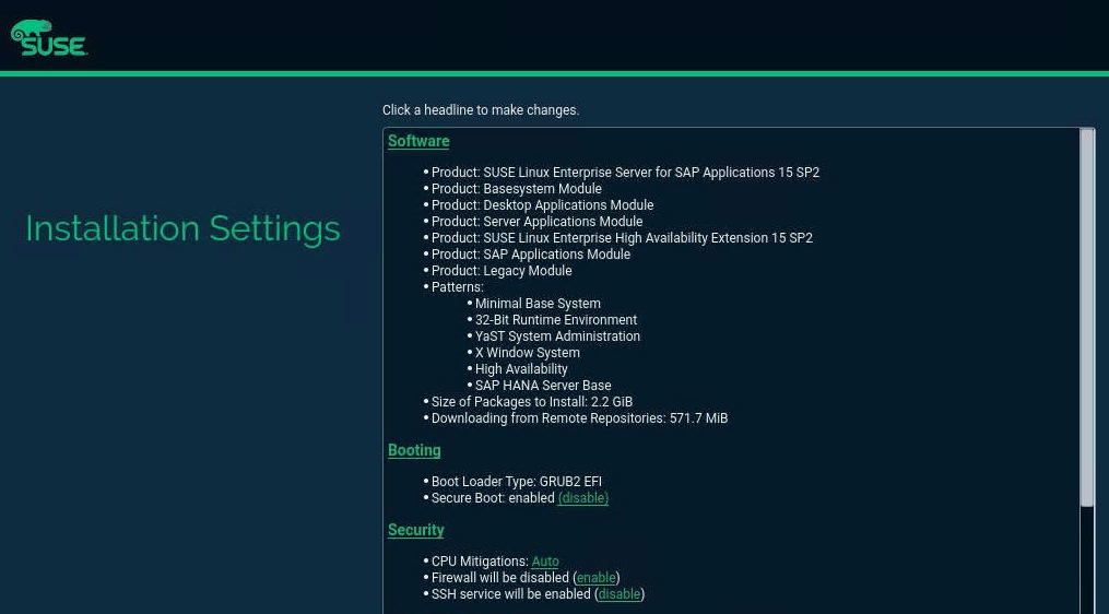
SUSE installer: Installation Settings
Perform the initial setup
After the first login, modify the system to fit into the existing infrastructure and to follow your company rules. Change the hostname and modify the network configuration according to your requirements. Proceed with the recommended OS settings as described in SAP note 2684254: SAP HANA DB: Recommended OS Settings for SLES for SAP Applications 15.
Disable OS-based memory-error monitoring
Linux supports two features related to error monitoring and logging: error detection and correction (EDAC) and mcelog. Both are common in most recent Linux distributions. Cisco recommends disabling EDAC based error collection, to allow all error reporting to be handled in firmware.
Disable EDAC by adding the kernel option edac_report=off. To add the kernel option, use this command:
# yast bootloader
Mcelog is enabled by default in most recent Linux distributions such as SLES 15 for SAP Applications. For customers who prefer to collect all diagnostic and fault information from OS resident tools, mcelog is recommended. Firmware logs may be incomplete when OS logging is enabled.
Configure Pure Storage UDEV rules
Configure the UDEV userspace manager. The most important parameters to be changed are nr_requests and scheduler. Create a rule set for the Pure Storage FlashArray//X:
# vi /etc/udev/rules.d/99-pure-storage.rules
# Recommended settings for Pure Storage FlashArray.
# Use none scheduler for high-performance solid-state storage
ACTION=="add|change", KERNEL=="sd*[!0-9]", SUBSYSTEM=="block", ENV{ID_VENDOR}=="PURE", ATTR{queue/scheduler}="none"
ACTION=="add|change", KERNEL=="dm-[0-9]*", SUBSYSTEM=="block", ENV{DM_NAME}=="3624a937*", ATTR{queue/scheduler}="none"
# Reduce CPU overhead due to entropy collection
ACTION=="add|change", KERNEL=="sd*[!0-9]", SUBSYSTEM=="block", ENV{ID_VENDOR}=="PURE", ATTR{queue/add_random}="0"
ACTION=="add|change", KERNEL=="dm*[!0-9]", SUBSYSTEM=="block", ENV{DM_NAME}=="3624a937*", ATTR{queue/add_random}="0"
# Spread CPU load by redirecting completions to originating CPU
ACTION=="add|change", KERNEL=="sd*[!0-9]", SUBSYSTEM=="block", ENV{ID_VENDOR}=="PURE", ATTR{queue/rq_affinity}="2"
ACTION=="add|change", KERNEL=="dm*[!0-9]", SUBSYSTEM=="block", ENV{DM_NAME}=="3624a937*", ATTR{queue/rq_affinity}="2"
# Set the HBA timeout to 60 seconds
ACTION=="add|change", KERNEL=="sd*[!0-9]", SUBSYSTEM=="block", ENV{ID_VENDOR}=="PURE", ATTR{device/timeout}="60"
Configure multipathing
Multipathing needs to be set to group_by_prio to separate traffic into asymmetric logical unit access (ALUA) priority groups for all PURE LUNs.
1. Create a /etc/multipath.conf configuration file:
# vi /etc/multipath.conf
devices {
device {
vendor "PURE"
product "FlashArray"
path_grouping_policy “group_by_prio”
hardware_handler "1 alua"
prio "alua"
failback "immediate"
fast_io_fail_tmo 10
max_sectors_kb 512
}
}
2. After modifying the UDEV rules and multipath configuration, re-create the initial RAM disk (initrd) for the system and reboot to make the changes take effect.
# dracut -f
Add SAP HANA partitions
Add the SAP HANA multipath LUNs from the preceding configuration example.
1. From the command line, list the available multipath LUNs:
# multipath -ll
3624a9370b9fcbe15cd0446a0000123a7 dm-6 PURE,FlashArray
size=18T features='0' hwhandler='1 alua' wp=rw
`-+- policy='service-time 0' prio=50 status=active
|- 2:0:0:3 sdd 8:48 active ready running
…
3624a9370b9fcbe15cd0446a0000123a3 dm-2 PURE,FlashArray
size=512G features='0' hwhandler='1 alua' wp=rw
`-+- policy='service-time 0' prio=50 status=active
|- 2:0:0:2 sdc 8:32 active ready running
…
3624a9370b9fcbe15cd0446a0000123af dm-4 PURE,FlashArray
size=6T features='0' hwhandler='1 alua' wp=rw
`-+- policy='service-time 0' prio=50 status=active
|- 2:0:0:1 sdb 8:16 active ready running
…
2. Construct an XFS file system for each LUN using the device World Wide ID (WWID) shown in the preceding command output:
# mkfs.xfs -f /dev/disk/by-id/dm-uuid-mpath-3624a9370b9fcbe15cd0446a0000123a7
# mkfs.xfs -f /dev/disk/by-id/dm-uuid-mpath-3624a9370b9fcbe15cd0446a0000123a3
# mkfs.xfs -f /dev/disk/by-id/dm-uuid-mpath-3624a9370b9fcbe15cd0446a0000123af
3. Create the mount points:
# mkdir -p /hana/log
# mkdir -p /hana/data
# mkdir -p /hana/shared
4. Create persistent mount points by adding the LUNs to /etc/fstab (end the stream with Ctrl+D):
# cat >> /etc/fstab
/dev/mapper/362…123a3 /hana/log xfs defaults 0 0
/dev/mapper/362…123a7 /hana/data xfs defaults 0 0
/dev/mapper/362…123af /hana/shared xfs defaults 0 0
5. Mount the logical volumes:
# mount -av
6. An SAP HANA scale out environment requires a persistent NFS SAP HANA shared volume mount point:
# cat >> /etc/fstab
<Pure NFS IP>:/hanashared /hana/shared nfs defaults,vers=3 0 0
In an SAP HANA scale out scenario, the SAP HANA storage connector API is responsible for mounting and managing the data and log volumes on each node. In this case, construct the XFS file systems and note the WWID, which is required during the SAP HANA installation process.
Configure SAP HANA performance settings
Apply SAP-recommended operating system settings and tuning options.
# saptune solution apply HANA
# saptune daemon start
Enable recommended software packages
Enable the recommended software.
1. Enable system use monitoring:
# systemctl enable sysstat
# systemctl start sysstat
2. Install IPv4 and IPv6 networking utilities:
# zypper in iputils
3. Install the supportutils, including the latest supportconfig package:
# zypper in supportutils
Fix BIOS boot-order priority
Reboot the server from the CLI. Connect to the IPMI address of the Cisco UCS C890 M5 server with your preferred browser. Use the ADMIN user to log on to IPMI.
1. At the top of the screen, choose Remote Control and Remote Console from the drop-down menu. The Launch Console button opens a new window with the console redirection.
2. After system initialization, the Cisco logo appears. Press Delete to enter the AMI BIOS setup utility.
3. In the BIOS setup utility, change to the Boot top menu and select UEFI Hard Disk Drive BBS Priorities.
4. Open Boot Option 1 and choose SUSE Linux Enterprise from the drop-down menu.
5. If the boot option UEFI Hard Disk: SUSE Linux Enterprise is not listed at the first position of the boot order, move it to the first position.
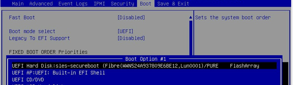
6. Change to the Save & Exit top menu and quit the setup utility with Save Changes and Reset.
Red Hat Enterprise Linux for SAP Solutions installation
Red Hat Enterprise Linux 8 introduces the concept of application streams. Multiple versions of user space components are now delivered and updated more frequently than are the core operating system packages. This approach gives you greater flexibility to customize Red Hat Enterprise Linux without affecting the underlying stability of the platform or specific deployments. Consult the RHEL 8 installation and configuration guide for instructions about downloading the appropriate RHEL for SAP Solutions installation image and follow the installation workflow. During the installation workflow, be sure to apply the best practices listed in SAP Note 2772999: Red Hat Enterprise Linux 8.x: Installation and Configuration.
The following supplemental RHEL information is available in the SAP Notes:
● SAP Note 2369910: SAP Software on Linux: General Information
● SAP Note 2772999: Red Hat Enterprise Linux 8.x: Installation and Configuration
● SAP Note 2777782: SAP HANA DB: Recommended OS Settings for RHEL 8
● SAP Note 2886607: Linux: Running SAP Applications compiled with GCC 9.x
● SAP Note 2382421: Optimizing the Network Configuration on HANA- and OS-Levels
Download and install the RHEL ISO installation image
At the release date of this document, SAP HANA 2.0 is supported up to RHEL 8.4. Download the RHEL 8 release from the Red Hat customer portal.
1. In the remote console window, select Virtual Media in the top menu.
2. Keep the device type set to ISO image and choose the RHEL for SAP Solutions 8.x ISO installation image.
3. Click the Mount button to mount the image and close the window.
4. In the BIOS Setup Utility Save & Exit top menu, select Save Changes and Reset to restart the server.
The Cisco UCS C890 M5 server will automatically boot from the mapped ISO installation source, and the RHEL installation wizard will start. Install and configure RHEL 8 for SAP Solutions according to the Red Hat configuration guide.
5. Follow the installation workflow:
◦ Use English as the installation and system default language and a keyboard layout according to your local preferences.
◦ Manually partitioning the system disks is strongly recommended, but you can join the /usr/sap and the root / directories as well.
◦ On the Network & Hostname configuration screen, enter the server’s short name <hostname> and not the fully qualified hostname.
◦ Select the correct timezone and verify that the date and time are set correctly. If applicable, configure a local NTP server.
Perform the initial setup
After the first login, modify the system to fit into the existing infrastructure and to follow the SAP best practices for RHEL 8 for SAP Solutions.
1. Register the host and apply the RHEL release lock to stay with an SAP HANA supported RHEL release when patching:
# subscription-manager release --set=8.<1|2>
2. Disable all repositories:
# subscription-manager repos --disable="*"
3. Enable the following repositories if you intend to use the server for the SAP HANA database only:
# subscription-manager repos \
--enable="rhel-8-for-$(uname -m)-baseos-e4s-rpms" \
--enable="rhel-8-for-$(uname -m)-appstream-e4s-rpms" \
--enable="rhel-8-for-$(uname -m)-sap-solutions-e4s-rpms" \
--enable="ansible-2.9-for-rhel-8-$(uname -m)-rpms"
4. Install the following additional software packages, which are required for SAP HANA environments:
# yum -y install ansible bind-utils compat-sap-c++9 expect krb5-workstation \
krb5-libs libaio libatomic libcanberra-gtk2 libnsl libibverbs libicu libtool-ltdl \ nfs-utils numactl openssl PackageKit-gtk3-module psmisc rsyslog sudo tcsh tuned \
tuned-profiles-sap-hana uuidd xfsprogs xorg-x11-xauth
5. For SAP HANA supportability purposes, consider installing the following packages as well:
# yum -y install cairo graphviz iptraf-ng lm_sensors net-tools
6. Install the following group and the SAP system role:
# yum group install Server
# yum -y install rhel-system-roles-sap
Apply the most current security patches
You should fully patch and reboot the Cisco UCS server before you proceed with the SAP HANA pre-configuration steps:
# yum -y update
Configure systemd tmpfiles behavior
Be sure that important lock files and sockets in /tmp will not be deleted by systemd-tmpfiles (end the stream with Ctrl+D):
# cat >> /etc/tmpfiles.d/sap.conf
# systemd.tmpfiles exclude file for SAP
# SAP software stores some important files in /tmp which should not be deleted \
automatically
# Exclude SAP socket and lock files
x /tmp/.sap*
# Exclude HANA lock file
x /tmp/.hdb*lock
# Exclude TREX lock file
x /tmp/.trex*lock
Configure Pure Storage UDEV rules
Configure the UDEV userspace manager. The most important parameters to be changed are nr_requests and scheduler. Create a rule set for the Pure Storage FlashArray//X:
# vi /etc/udev/rules.d/99-pure-storage.rules
# Recommended settings for Pure Storage FlashArray.
# Use none scheduler for high-performance solid-state storage
ACTION=="add|change", KERNEL=="sd*[!0-9]", SUBSYSTEM=="block", ENV{ID_VENDOR}=="PURE", ATTR{queue/scheduler}="none"
ACTION=="add|change", KERNEL=="dm-[0-9]*", SUBSYSTEM=="block", ENV{DM_NAME}=="3624a937*", ATTR{queue/scheduler}="none"
# Reduce CPU overhead due to entropy collection
ACTION=="add|change", KERNEL=="sd*[!0-9]", SUBSYSTEM=="block", ENV{ID_VENDOR}=="PURE", ATTR{queue/add_random}="0"
ACTION=="add|change", KERNEL=="dm*[!0-9]", SUBSYSTEM=="block", ENV{DM_NAME}=="3624a937*", ATTR{queue/add_random}="0"
# Spread CPU load by redirecting completions to originating CPU
ACTION=="add|change", KERNEL=="sd*[!0-9]", SUBSYSTEM=="block", ENV{ID_VENDOR}=="PURE", ATTR{queue/rq_affinity}="2"
ACTION=="add|change", KERNEL=="dm*[!0-9]", SUBSYSTEM=="block", ENV{DM_NAME}=="3624a937*", ATTR{queue/rq_affinity}="2"
# set HANA devices to be 512kB rather than 4MB max size
ACTION=="add|change", KERNEL=="sd*[!0-9]", SUBSYSTEM=="block", ENV{ID_VENDOR}=="PURE", ATTR{queue/max_sectors_kb}="512"
ACTION=="add|change", KERNEL=="dm-[0-9]*", SUBSYSTEM=="block", ENV{DM_NAME}=="3624a937*", ATTR{queue/max_sectors_kb}="512"
# Set the HBA timeout to 60 seconds
ACTION=="add|change", KERNEL=="sd*[!0-9]", SUBSYSTEM=="block", ENV{ID_VENDOR}=="PURE", ATTR{device/timeout}="60"
Set DM devices number of requests to 1024
ACTION=="add|change", KERNEL=="dm-[0-9]*", SUBSYSTEM=="block", ENV{DM_NAME}=="3624a937*", ATTR{queue/nr_requests}="1024"
Configure multipathing
Multipathing needs to be set to group_by_prio to separate traffic into ALUA priority groups for all PURE LUNs.
1. Create a /etc/multipath.conf configuration file:
# vi /etc/multipath.conf
devices {
device {
vendor "PURE"
product "FlashArray"
path_grouping_policy “group_by_prio”
hardware_handler "1 alua"
prio "alua"
failback "immediate"
fast_io_fail_tmo 10
max_sectors_kb 4096
}
}
2. After you modify the UDEV rules and multipath configuration, re-create the system initrd and reboot to make the changes take effect.
# dracut -f
Add SAP HANA partitions
Add the SAP HANA multipath LUNs from the preceding configuration example.
1. From the command line, list the available multipath LUNs:
# multipath -ll
3624a9370b9fcbe15cd0446a0000123a8 dm-5 PURE,FlashArray
size=18T features='0' hwhandler='1 alua' wp=rw
`-+- policy='service-time 0' prio=50 status=active
|- 16:0:0:7 sdd 8:48 active ready running
…
3624a9370b9fcbe15cd0446a0000123a4 dm-4 PURE,FlashArray
size=512G features='0' hwhandler='1 alua' wp=rw
`-+- policy='service-time 0' prio=50 status=active
|- 16:0:0:6 sdc 8:32 active ready running
…
3624a9370b9fcbe15cd0446a0000123ae dm-3 PURE,FlashArray
size=6T features='0' hwhandler='1 alua' wp=rw
`-+- policy='service-time 0' prio=50 status=active
|- 16:0:0:1 sdb 8:16 active ready running
…
2. Construct an XFS file system for each LUN using the device WWID shown in the preceding command output:
# mkfs.xfs -f /dev/disk/by-id/dm-uuid-mpath-3624a9370b9fcbe15cd0446a0000123a8
# mkfs.xfs -f /dev/disk/by-id/dm-uuid-mpath-3624a9370b9fcbe15cd0446a0000123a4
# mkfs.xfs -f /dev/disk/by-id/dm-uuid-mpath-3624a9370b9fcbe15cd0446a0000123ae
Create the mount points:
# mkdir -p /hana/log
# mkdir -p /hana/data
# mkdir -p /hana/shared
Create persistent mount points by adding the LUNs to /etc/fstab (end the stream with Ctrl+D):
# cat >> /etc/fstab
/dev/mapper/362…123a4 /hana/log xfs defaults 0 0
/dev/mapper/362…123a8 /hana/data xfs defaults 0 0
/dev/mapper/362…123ae /hana/shared xfs defaults 0 0
3. Mount the logical volumes:
# mount -av
4. An SAP HANA scale out environment requires a persistent NFS SAP HANA shared volume mount point:
# cat >> /etc/fstab
<Pure NFS IP>:/hanashared /hana/shared nfs defaults,vers=3 0 0
In an SAP HANA scale out scenario, the SAP HANA storage connector API is responsible for mounting and managing the data and log volume on each node. In this case, construct the XFS file systems and note the WWID, which is required during the SAP HANA installation.
Configure server with the RHEL system roles for SAP
With the Ansible Engine installed, use the Ansible playbook to configure the host:
1. Create the file sap-hana.yml (end the stream with Ctlr+D):
# cat >> sap-hana.yml
---
- hosts: localhost
vars:
ansible_connection: local
sap_preconfigure_fail_if_reboot_required: no
sap_hana_preconfigure_fail_if_reboot_required: no
sap_hana_preconfigure_update: yes
roles:
- role: sap-preconfigure
- role: sap-hana-preconfigure
2. Configure the server according to the applicable SAP notes for SAP HANA and run the Ansible playbook:
# ansible-playbook sap-hana.yml
3. Reboot the server.
Disable OS-based memory error monitoring
Linux supports two features related to error monitoring and logging: error detection and correction (EDAC) and mcelog. Both are common in most recent Linux distributions. Cisco recommends disabling EDAC based error collection, to allow all error reporting to be handled in firmware.
You can disable EDAC by adding the option edac_report=off to the kernel command line. Mcelog is enabled by default in most recent Linux distributions, such as Red Hat Enterprise Linux 8.
For customers who prefer to collect all diagnostic and fault information from OS resident tools, mcelog is recommended. Firmware logs may be incomplete when OS logging is enabled.
Fix BIOS boot order priority
Reboot the server from the CLI. Connect to the IPMI address of the Cisco UCS C890 M5 Rack Server with your preferred browser. Use the ADMIN user to log on to IPMI.
1. At the top of the screen, choose Remote Control and Remote Console from the drop-down menu. The Launch Console button opens a new window with the console redirection.
2. After system initialization the Cisco logo appears. Press Delete to enter the AMI BIOS setup utility.
3. In the BIOS setup utility change to the Boot top menu and select UEFI Hard Disk Drive BBS Priorities
4. Open Boot Option 1 and choose Red Hat Enterprise Linux from the drop-down menu.
5. If the boot option UEFI Hard Disk: Red Hat Enterprise Linux is not listed at the first position of the boot order, move it to the first position.
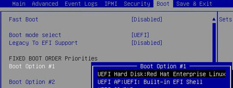
6. Change to the Save & Exit top menu and quit the setup utility with Save Changes and Reset.
Persistent memory configuration
Configure and manage Intel Optane PMem modules from the Linux command line. First install the management utilities ipmctl and ndctl required to manage the libnvdimm (non-volatile memory device) sub-system in the Linux kernel. For additional information, refer to the IPMCTL User Guide and the NDCTL User Guide.
Install the host utilities
Open a SSH prompt as root user to install the host tools and follow the steps here according to the Linux OS you are using.
SLES for SAP Applications
Follow these steps for SLES for SAP Applications.
1. Install the ipmctl host utility:
# zypper in ipmctl
2. Install the ndctl utility:
# zypper in ndctl
RHEL for SAP Solutions
Follow these steps for RHEL for SAP Solutions.
The ipmctl package is available in the Extra Packages for Enterprise Linux (EPEL) repository.
1. EPEL packages assume that the codeready-builder repository is enabled:
# subscription-manager repos --enable "codeready-builder-for-rhel-8-$(arch)-rpms"
2. Enable the EPEL 8 repository or download the required Red Hat Package Manager (RPM) file from https://dl.fedoraproject.org/pub/epel/8/Everything/x86_64/Packages/ manually:
# yum install https://dl.fedoraproject.org/pub/epel/epel-release-latest-8.noarch.rpm
# yum info ipmctl
# yum -y install ipmctl
3. Install the ndctl utility:
# yum -y install ndctl
Verify and configure persistent memory
Use these steps to verify and configure persistent memory.
1. Verify that the persistent memory modules have been discovered and the software can communicate with them:
# ipmctl show -dimm
DimmID | Capacity | LockState | HealthState | FWVersion
===============================================================
0x0001 | 502.599 GiB | Disabled | Healthy | 01.02.00.5435
0x0011 | 502.599 GiB | Disabled | Healthy | 01.02.00.5435
0x0021 | 502.599 GiB | Disabled | Healthy | 01.02.00.5435
.
.
.
0x7121 | 502.599 GiB | Disabled | Healthy | 01.02.00.5435
2. Add a UDEV rule to help ensure persistent device naming. Update the system initrd as well:
# vi /etc/udev/rules.d/60-persistent-storage.rules
# PMEM devices
KERNEL=="pmem*", ENV{DEVTYPE}=="disk", ATTRS{uuid}=="?*", SYMLINK+="disk/by-id/pmem-$attr{uuid}"
KERNEL=="pmem*", ENV{DEVTYPE}=="disk", ATTRS{uuid}=="?*", SYMLINK+="disk/by-uuid/$attr{uuid}"
# dracut -f
3. By default, the ipmctl command provisions Intel Optane PMem in App Direct mode with interleaving enabled, which increases the throughput of write and read operations to the persistent memory area. Create the goal:
# ipmctl create -goal
The following configuration will be applied:
SocketID | DimmID | MemorySize | AppDirect1Size | AppDirect2Size
==================================================================
0x0000 | 0x0001 | 0.000 GiB | 502.000 GiB | 0.000 GiB
0x0000 | 0x0011 | 0.000 GiB | 502.000 GiB | 0.000 GiB
0x0000 | 0x0021 | 0.000 GiB | 502.000 GiB | 0.000 GiB
.
.
.
Do you want to continue? [y/n]
4. Confirm by selecting Y and reboot the server to complete the memory provisioning (goal) process.
5. Verify that the regions have been created:
# ipmctl show -region
SocketID | ISetID | Persistent | Capacity | FreeCapacity | HealthState
| | MemoryType | | |
=================================================================================
0x0000 | 0x039278592ccc | AppDirect | 3012.00 GiB | 0.000 GiB | Healthy
0x0001 | 0x7e2a77612ccc | AppDirect | 3012.00 GiB | 0.000 GiB | Healthy
0x0002 | 0xf78a756b2ccc | AppDirect | 3012.00 GiB | 0.000 GiB | Healthy
0x0003 | 0xe560735a2ccc | AppDirect | 3012.00 GiB | 0.000 GiB | Healthy
0x0004 | 0xf396715f2ccc | AppDirect | 3012.00 GiB | 0.000 GiB | Healthy
0x0005 | 0xc5f27d592ccc | AppDirect | 3012.00 GiB | 0.000 GiB | Healthy
0x0006 | 0x7e0074502ccc | AppDirect | 3012.00 GiB | 0.000 GiB | Healthy
0x0007 | 0x558c73622ccc | AppDirect | 3012.00 GiB | 0.000 GiB | Healthy
6. Create a namespace for each of the eight regions:
# ndctl create-namespace --continue
7. The default syntax creates a namespace with direct access (DAX) support, mode=fsdax, required by SAP HANA to properly utilize Intel Optane PMem. Verify that the namespace has been created successfully:
# ndctl list -u
[
{
"dev":"namespace1.0",
"mode":"fsdax",
"map":"dev",
"size": "2964.94 GiB (3183.58 GB)",
"uuid":"de793a2f-5763-4d82-b2c7-59b73721a3e9",
"sector_size":512,
"align":2097152,
"blockdev":"pmem1"
},
.
.
.
]
8. The assigned device name for the namespaces is usually /dev/pmemX, where X denotes the nonuniform memory access (NUMA) node mapping of the underlying hardware. Construct an XFS file system on the block devices:
# for i in {0..7}; do mkfs.xfs -f -d su=2m,sw=1 -m reflink=0 /dev/pmem$i; done
9. Create directories and mount the block devices using the DAX file system option:
# for i in {0..7}; do mkdir -p /hana/pmem/nvmem$i; done
# for i in {0..7}; do mount -t xfs -o dax,lazytime /dev/pmem$i \
/hana/pmem/nvmem$i; done
10. Change the permission of the mount points:
# chmod 755 /hana/pmem/nvmem*
11. Identify the UUIDs of the persistent memory namespaces:
# ndctl list |egrep 'uuid|blockdev'
"uuid":"de793a2f-5763-4d82-b2c7-59b73721a3e9",
"blockdev":"pmem1"
"uuid":"2a2b109c-9b3d-463a-8d12-6a51237b4251",
"blockdev":"pmem3"
"uuid":"d7276772-af1d-496e-a5b2-3f9d2a19f6c4",
"blockdev":"pmem5"
"uuid":"24057307-8d32-4aa5-b1dc-858006ed4c83",
"blockdev":"pmem7"
"uuid":"1466813e-b789-452d-bb27-464795f9a32f",
"blockdev":"pmem0"
"uuid":"98d295c1-8bf9-4b75-a62c-1e42f337f9f0",
"blockdev":"pmem2"
"uuid":"b0b8f716-e23a-4e02-8d11-b471b348d373",
"blockdev":"pmem4"
"uuid":"2b0ade1b-8b64-4a55-90d6-1f69ee0695c0",
"blockdev":"pmem6"
Add the mount points to /etc/fstab and make them persist:
# vi /etc/fstab
UUID=1466813e-b789-452d-bb27-464795f9a32f /hana/pmem/nvmem0 xfs dax,lazytime 1 2
UUID=de793a2f-5763-4d82-b2c7-59b73721a3e9 /hana/pmem/nvmem1 xfs dax,lazytime 1 2
UUID=98d295c1-8bf9-4b75-a62c-1e42f337f9f0 /hana/pmem/nvmem2 xfs dax,lazytime 1 2
UUID=2a2b109c-9b3d-463a-8d12-6a51237b4251 /hana/pmem/nvmem3 xfs dax,lazytime 1 2
UUID=b0b8f716-e23a-4e02-8d11-b471b348d373 /hana/pmem/nvmem4 xfs dax,lazytime 1 2
UUID=d7276772-af1d-496e-a5b2-3f9d2a19f6c4 /hana/pmem/nvmem5 xfs dax,lazytime 1 2
UUID=2b0ade1b-8b64-4a55-90d6-1f69ee0695c0 /hana/pmem/nvmem6 xfs dax,lazytime 1 2
UUID=24057307-8d32-4aa5-b1dc-858006ed4c83 /hana/pmem/nvmem7 xfs dax,lazytime 1 2
This concludes the Linux-specific setup of Intel Optane PMem. After you finish the SAP HANA installation, you must configure SAP HANA to enable the use of Intel Optane PMem.
All version-specific SAP installation and administration documentation is available from the SAP HANA Help portal: https://help.sap.com/hana. Please refer to the official SAP documentation, which describes the various SAP HANA installation options.
Note: Review all relevant SAP Notes related to the SAP HANA installation for any recent changes.
SAP HANA platform 2.0 installation
The official SAP documentation describes in detail how to install the HANA software and its required components. All required file systems are already mounted for the installation.
Install an SAP HANA scale up solution
Download and extract the SAP HANA Platform 2.0 software to an installation sub-folder of your choice. Follow the installation workflow of the SAP HANA Database Lifecycle Manager (hdblcm) and provide the user passwords when asked.
1. Change to the folder <installation path>/DATA_UNITS/HDB_LCM_Linux_X86_64.
2. Adapt the following command according to your SAP system ID (SID), SAP system number, host name, and required components:
# ./hdblcm --action install --components=server,client --install_hostagent \
--number <SAP System ID> --sapmnt=/hana/shared --sid=<SID> \
--hostname=<hostname> --certificates_hostmap=<hostname>=<map name>
3. Switch the user to <sid>adm to verify that SAP HANA is up and running:
# sapcontrol -nr <SAP System ID> -function GetProcessList
Install an SAP HANA scale out solution
SAP HANA includes a ready-to-use storage connector client to manage Fibre Channel attached devices with native multipathing. This feature enables host automatic-failover at the block storage level, which is required for successful failover to a standby host.
The fcCLient/fcClientLVM implementation uses standard Linux commands, such as multipath and sg_persist. It is responsible for mounting the SAP HANA data and log volumes and implements the fencing mechanism during host failover by means of SCSI-3 persistent reservations.
For a scale out installation, the SAP HANA data and log volumes are not mounted upfront and the SAP HANA shared volume is NFS mounted on all hosts.
1. Prepare an installation configuration file for the SAP Storage Connector API to use during the installation process. The file itself is not required after the installation process is complete:
# vi /tmp/cisco/global.ini
[communication]
listeninterface = .global
[persistence]
basepath_datavolumes = /hana/data/ANA
basepath_logvolumes = /hana/log/ANA
basepath_shared=yes
[storage]
ha_provider = hdb_ha.fcClient
partition_*_*__prtype = 5
partition_1_data__wwid = 3624a9370b9fcbe15cd0446a000011fa4
partition_1_log__wwid = 3624a9370b9fcbe15cd0446a000011fa5
.
.
.
[trace]
ha_fcclient = info
2. Change to the folder <installation path>/DATA_UNITS/HDB_LCM_Linux_X86_64.
3. Adapt the following command according to your SAP SID, SAP system number, host name, and required components:
# ./hdblcm --action install --components=server,client --install_hostagent \
--number <SAP System ID> --sapmnt=/hana/shared --sid=<SID> \
--storage_cfg=/tmp/cisco --hostname=<hostname> \
--certificates_hostmap=<hostname>=<map name>
4. Switch the user to <sid>adm to verify SAP HANA is up and running:
# sapcontrol -nr <SAP System ID> -function GetProcessList
# sapcontrol -nr <SAP System ID> -function GetSystemInstanceList
5. Be sure that the internode network setup is complete and working. Change the SAP HANA inter-service network communication to internal:
# /hana/shared/<SID>/hdblcm/hdblcm --action=configure_internal_network --listen_interface=internal --internal_address=<internode network>/<network mask>
Configure SAP HANA to use Intel Optane PMem
In a multi-tenant database architecture create sub directories in the mounted /hana/pmem/nvmem* directories. Here is an example:
# mkdir /hana/pmem/nvmem*/DB1
# mkdir /hana/pmem/nvmem*/DB2
Adapt the directory permissions and assign the database user and group. Here is an example:
# chmod 755 /hana/pmem/nvmem*/DB*
# chown db1adm:sapsys /hana/pmem/nvmem*/DB1
# chown db2adm:sapsys /hana/pmem/nvmem’/DB2
For a single instance, just assign the database user and group to the /hana/pmem/nvmem* mount points.
Specify the SAP HANA PMem base path
Enable SAP HANA to use the nonvolatile memory and add the DAX volumes to the SAP HANA configuration file global.ini.
1. Configure the required SAP HANA parameter basepath_persistent_memory_volumes in the persistence section. Separate multiple locations with semicolons.
(<sid>adm) # cdglo
(<sid>adm) # vi hdb/custom/config/global.ini
[persistence]
basepath_datavolumes = /hana/data/<SID>
basepath_logvolumes = /hana/log/<SID>
basepath_persistent_memory_volumes = /hana/pmem/nvmem0;/hana/pmem/nvmem1;/hana/pmem/nvmem2;/hana/pmem/nvmem3; hana/pmem/nvmem4;/hana/pmem/nvmem5;/hana/pmem/nvmem6;/hana/pmem/nvmem7
2. For a multi-tenant database server, the parameter needs to be configured separately for both example instances DB1 and DB2:
(db1adm) # cdglo
(db1adm) # vi hdb/custom/config/global.ini
[persistence]
basepath_datavolumes = /hana/data/DB1
basepath_logvolumes = /hana/log/DB1
basepath_persistent_memory_volumes = /hana/pmem/nvmem0/DB1;/hana/pmem/nvmem1/DB1;/hana/pmem/nvmem2/DB1;/hana/pmem/nvmem3/DB1;/hana/pmem/nvmem4/DB1;/hana/pmem/nvmem5/DB1;/hana/pmem/nvmem6/DB1;/hana/pmem/nvmem7/DB1
(db2adm) # cdglo
(db2adm) # vi hdb/custom/config/global.ini
[persistence]
basepath_datavolumes = /hana/data/DB2
basepath_logvolumes = /hana/log/DB2
basepath_persistent_memory_volumes = /hana/pmem/nvmem0/DB2;/hana/pmem/nvmem1/DB2;/hana/pmem/nvmem2/DB2;/hana/pmem/nvmem3/DB2;/hana/pmem/nvmem4/DB2;/hana/pmem/nvmem5/DB2;/hana/pmem/nvmem6/DB2;/hana/pmem/nvmem7/DB2
3. Restart the SAP HANA database instance to activate the parameter change. SAP HANA automatically verifies during startup the DAX-enabled file system, and all column store tables will use persistent memory by default afterward.
Cisco uses best-in-class server and network components as a foundation for a variety of enterprise application workloads. With Cisco UCS C890 M5 Rack Servers for SAP HANA, you can deploy a flexible, converged infrastructure solution designed for mission-critical workloads for which performance and memory size are key attributes.
The eight-socket server delivers exceptional performance and is sized, configured, and deployed to match the SAP HANA appliance key performance metrics demanded by SAP. With standard configuration options including eight 25-Gbps SFP Ethernet ports, and four 32-Gbps Fibre Channel ports, this rack server is well suited for integration into a new or existing FlashStack environment.
FlashStack Data Center is predesigned to provide agility for large enterprise data centers, with high availability and storage scalability. With a FlashStack solution, customers have a secure, integrated, and optimized stack that includes computing, networking, and storage resources that are sized, configured, and deployed in a flexible manner.
FlashStack is a flexible infrastructure platform composed of presized storage, networking, and server components. It is designed to ease your IT transformation and operational challenges with high efficiency and low risk.
FlashStack differs from other solutions and is so powerful for SAP environments because it offers the following features:
● It uses integrated, validated technologies from industry leaders and top-tier software partners.
● Cisco UCS stateless computing architecture provided by Cisco UCS service profile allows fast, nondisruptive workload changes to be implemented simply and seamlessly across the integrated Cisco UCS infrastructure and Cisco x86 servers.
● It provides a single platform built from unified computing, fabric, and storage technologies, allowing you to scale to large-scale data centers without architectural changes.
● The Cisco Intersight platform provides centralized, simplified management of all infrastructure resources, including the FlashArray//X.
● Evergreen storage means that you will never pay for more storage than you need but will still have ample storage available on demand when you need it.
● A flexible cooperative support model resolves issues rapidly and spans both new and existing products.
For more information
For additional information, see the resources listed in this section.
Cisco Unified Computing System
● Cisco UCS C890 M5 Rack Server data sheet: https://www.cisco.com/c/en/us/products/collateral/servers-unified-computing/ucs-c-series-rack-servers/datasheet-c78-744647.html
● Intel Optane persistent memory and SAP HANA platform configuration:
https://www.intel.com/content/www/us/en/big-data/partners/sap/sap-hana-and-intel-optane-configuration-guide.html
● Cisco UCS for SAP HANA with Intel Optane Persistent Memory Module: https://www.cisco.com/c/dam/en/us/products/servers-unified-computing/ucs-b-series-blade-servers/whitepaper-c11-742627.pdf
● Cisco Intersight platform:
https://www.cisco.com/c/en/us/products/servers-unified-computing/intersight/index.html
Network and management
● Cisco MDS 9000 Family multilayer switches:
http://www.cisco.com/c/en/us/products/storage-networking/mds-9000-series-multilayer-switches/index.html
● Cisco Nexus 9000 Series switches:
https://www.cisco.com/c/en/us/products/switches/nexus-9000-series-switches/index.html
SAP HANA
● SAP HANA platform on SAP Help portal:
https://help.sap.com/viewer/p/SAP_HANA_PLATFORM
● SAP HANA TDI overview:
https://www.sap.com/documents/2017/09/e6519450-d47c-0010-82c7-eda71af511fa.html
● SAP HANA TDI storage requirements:
https://www.sap.com/documents/2015/03/74cdb554-5a7c-0010-82c7-eda71af511fa.html
● SAP HANA network requirements:
https://www.sap.com/documents/2016/08/1cd2c2fb-807c-0010-82c7-eda71af511fa.html
● SAP HANA business continuity with SAP HANA system replication and SUSE cluster:
https://www.cisco.com/c/en/us/solutions/collateral/data-center-virtualization/sap-applications-on-cisco-ucs/whitepaper-C11-734028.html
● SAP HANA high availability with SAP HANA system replication and RHEL cluster:
https://www.cisco.com/c/en/us/solutions/collateral/data-center-virtualization/sap-applications-on-cisco-ucs/whitepaper-c11-735382.pdf
Interoperability matrixes
● Cisco Nexus and Cisco MDS interoperability matrix:
https://www.cisco.com/c/en/us/td/docs/switches/datacenter/mds9000/interoperability/matrix/intmatrx/Matrix1.html
● SAP Note 2235581: SAP HANA: Supported Operating Systems:
https://launchpad.support.sap.com/#/notes/2235581
● SAP certified and supported SAP HANA hardware:
https://www.sap.com/dmc/exp/2014-09-02-hana-hardware/enEN/index.html
Pure Storage
● SAP HANA implementation and best practices
For comments and suggestions about this guide and related guides, join the discussion on Cisco Community at https://cs.co/en-cvds.