Future-Ready Workspaces: Cisco Wi-Fi 7, Smart Switches, and Panduit Infrastructure White Paper
Available Languages
Bias-Free Language
The documentation set for this product strives to use bias-free language. For the purposes of this documentation set, bias-free is defined as language that does not imply discrimination based on age, disability, gender, racial identity, ethnic identity, sexual orientation, socioeconomic status, and intersectionality. Exceptions may be present in the documentation due to language that is hardcoded in the user interfaces of the product software, language used based on RFP documentation, or language that is used by a referenced third-party product. Learn more about how Cisco is using Inclusive Language.
The transition to Wi-Fi 7 (IEEE 802.11be) represents a paradigm shift in wireless networking, offering multi-gigabit speeds, ultra-low latency, and enhanced spectral efficiency. However, these advancements place unprecedented demands on the underlying physical infrastructure. To fully realize the potential of Wi-Fi 7, organizations must move beyond traditional cabling and power distribution methods, which often become bottlenecks in high-density, mission-critical environments. Cisco Wireless access points leverage multi-gigabit Ethernet, and PoE+ or UPOE to deliver the full benefits of Wi-Fi 7 required for modern digital experiences from high definition, real-time video collaboration to virtual, augmented and mixed reality.
This white paper details a strategic engineering alliance between Cisco and Panduit, designed to provide a robust, future-ready foundation for a Future-Proofed Workplace. By integrating Cisco’s AI-native Catalyst 9000/C9350 series switches with Panduit’s high-performance Vari-MaTriX Cat6A cabling and innovative Fault Managed Power System (FMPS), this architecture ensures seamless, high-speed connectivity and reliable power delivery. The solution addresses critical challenges—including high availability, wireless signal attenuation, EMI, and power constraints—while supporting sustainability goals through intelligent energy management. This joint approach enables enterprises to deploy a scalable, standards-based ecosystem that protects long-term ROI, simplifies operations, and provides the resilience required for the modern digital era.
The exponential growth of connected devices, real-time applications, and immersive digital experiences is pushing wireless networks to their limits. Wi-Fi 7 (IEEE 802.11be) is the next-generation wireless standard designed to meet these demands, with multigigabit speeds, ultra-low latency, enhanced spectrum efficiency, and best-in-class security performance.
For IT and OT leaders, Wi-Fi 7 is not just about speed. It is about enabling automation, mobility, and data-driven operations at scale. From smart factories to corporate offices, seamless and secure wireless connectivity is now mission-critical. To fully realize the benefits of Wi-Fi 7, organizations need a robust and scalable infrastructure, from the hardware to the physical layer. A fast and reliable wireless connection is a business necessity, for both employees and customers using the network. Therefore, organizations must prepare their structured cabling and network equipment infrastructure to ensure the robust, seamless operation of Wi-Fi 7 connections.
In this white paper, we will explain the value proposition between Cisco and Panduit, leaders in network and physical infrastructure solutions, offering a powerful combination of technologies and expertise to help enterprise organizations successfully deploy Wi-Fi 7-ready architectures that are secure, high-performing, and future-ready.
Wi-Fi standards update: Wi-Fi 7
Over the past two decades, Wi-Fi technology has transformed from a convenience into a mission-critical network service. Each generation of Wi-Fi has improved in terms of throughput, latency, security, and spectral efficiency.
Wi-Fi 7 marks the most significant leap to date, introducing innovations that make it ideal for demanding applications across enterprise, industrial, corporate, and public environments.
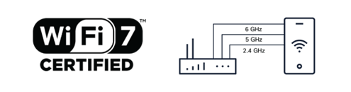
Wi-Fi 7 spectrum
Wi-Fi 7 leverages newly available spectrum in the 6-GHz band whose adoption began with Wi-Fi 6E. With the potential for as much as 1200 MHz of additional spectrum, the 6-GHz band enables greater speed through wider channels.
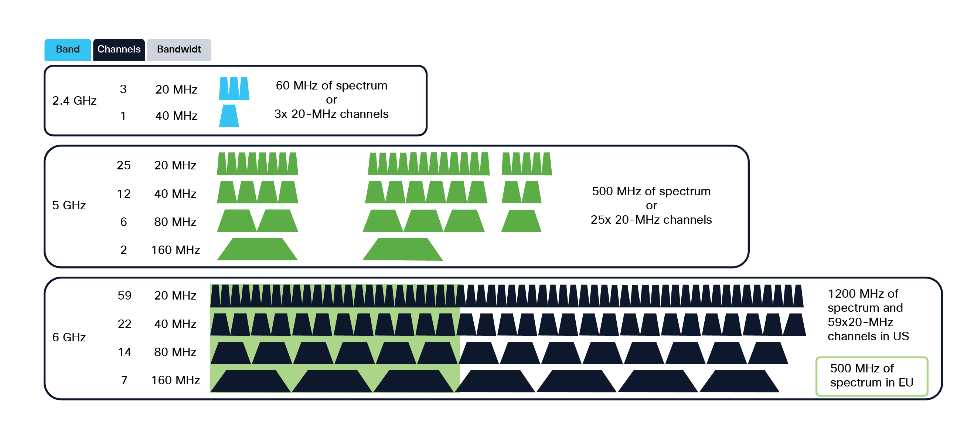
Channels available in the Wi-Fi 7 bands
Wi-Fi 7 represents the latest evolution in wireless technology, building upon the foundation laid by Wi-Fi 6 and 6E. It introduces a range of enhancements designed to meet the ever-growing requirements of modern applications. Key features of Wi-Fi 7 include multilink operation, wider channels (up to 320 MHz), higher modulation rates (4096-QAM), and improved efficiency and reliability.
Table 1. Comparison of Wi-Fi 6 and Wi-Fi 7 features
| Feature |
Wi-Fi 6 |
Wi-Fi 7 |
Benefit |
| Channel width |
Up to 160 MHz |
Up to 320 MHz |
2× data rate potential |
| Modulation |
1024-QAM |
4096-QAM |
+20% throughput efficiency |
| Multiple-Input, Multiple Output (MIMO) |
Up to 8×8 |
Still up to 16×16 (theoretical) |
Higher density and concurrency |
| Multilink operation |
X No |
ü Yes |
Combines 2.4-, 5-, and 6-GHz links |
| Latency |
10 to 20ms |
<2ms possible |
Ideal for AR/VR, gaming |
| Target applications |
Home/office Wi-Fi |
AR/VR, 8K video, high-speed LAN replacement |
Future-ready performance, conversational AI |
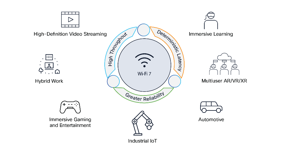
Wi-Fi 7 benefits and use cases
● Multilink operation: Simultaneous use of multiple bands/channels increases throughput and reliability, reducing latency and congestion.
● 320-MHz channels: Wider channels support higher data rates, doubling the throughput compared to Wi-Fi 6E’s 160-MHz channels.
● 4096-QAM: Higher modulation enables greater spectral efficiency, increasing maximum theoretical speeds.
● Improved determinism: Enhanced scheduling and resource management offer more predictable performance, crucial for mission-critical applications.
● Reduced latency: Essential for real-time applications like AR/VR and industrial control systems.
● Target Wake Time enhancements: Improved power efficiency in IoT devices.
Likewise, reference frameworks and standards have been developed that allow for the holistic design of the physical network infrastructure. To this end, organizations such as BISCI have developed the ANSI/BICSI 007-2024 guide, Information Communication Technology Design and Implementation Practices for Intelligent Buildings and Premises, which establishes the guidelines and recommendations of experts for the design of the physical network infrastructure, such as the type of structured cabling required, location, density, cabling for access points, cable routing in different routes, correct cable grounding, racks, cabinets, etc. This standard is intended to be used for any size of building and can be applied to residential and other premises (e.g., commercial, industrial, healthcare, educational, etc.) in all markets. It is written for use in the design and implementation of the structured cabling systems used to support building or on-premises systems which can be integrated using common infrastructure.
The ANSI/BISCI standard may be used to determine design requirements in conjunction with the system owner, occupant, or other project consultants. It provides a reference of common technology and design practices but is not intended to be used by design professionals as their sole reference or as a step-by-step design guide.
ANSI/BICSI 007-2024, Information Communication Technology Design and Implementation Practices for Intelligent Buildings and Premises
Finally, in its new standard for Wi-Fi 7, the IEEE establishes the minimum transmission requirements for speed and energy, such as the 802.3bz standard that defines 2.5GBASE-T and 5GBASE-T, as well as the 802.3bt standard that defines Cisco UPOE®, supporting 60W, and UPOE+, supporting up to 90W, ensuring sufficient power for Wi-Fi 7 and future networks, as well as a wide range of Power over Ethernet (PoE)-enabled devices, from cameras to digital signage to smart building automation devices.
Table 2. Types of Power over Ethernet
| Spec |
Known as |
Class |
Min PSE output power |
Min PD input power |
| Type 1 IEEE 802.3af |
PoE |
Class 1 |
4W |
3.84W |
|
|
Class 2 |
7W |
6.49W |
|
|
|
Class 3 |
15.4W |
12.95W |
|
| Type 2 IEEE 802.3at |
PoE+ |
Class 4 |
30W |
25.5W |
| Type 3 IEEE 802.3bt |
PoE++ |
Class 5 |
40W |
32W |
|
|
Class 6 |
60W |
51W |
|
| Type 4 IEEE 802.3bt |
PoE++ |
Class 7 |
60W to 75W |
51W to 62W |
|
|
Class 8 |
90W |
71.3W |
|
| Cisco proprietary |
UPOE |
|
60W |
51 W |
| UPOE+ |
|
90W |
71.3W |
Designing and deploying a high-speed and reliable Wi-Fi network
In the era of Wi-Fi 7, delivering a seamless, fast, and reliable wireless experience is no longer optional—it's a business-critical enabler. With new use cases like high-definition video collaboration, conversational AI, augmented reality, robotics, and digital twin technologies, network performance directly impacts employee productivity, customer satisfaction, and operational efficiency.
However, deploying Wi-Fi 7 comes with challenges:
● Signal attenuation through walls, machinery, or dense shelving
● Interference and contention with neighboring access points
● Increased density of devices (IoT, sensors, mobile endpoints)
● Higher power and data throughput requirements at the edge
● Energy efficiency to achieve sustainability goals
Wi-Fi 7 has transitioned from a niche feature to a mandatory specification in the high-end mobile market as well. Flagship integration in 2025 was demonstrated by Apple launching its N1-equipped iPhone 17 series and Samsung releasing the Galaxy Z Flip 7 with Wi-Fi 7 capabilities. This confirms critical volume commitments from the world's largest mobile device manufacturers.
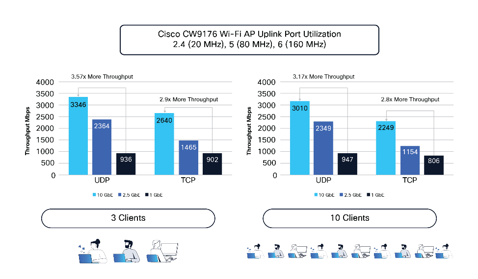
Comparison of standards development for Wi-Fi and structured cabling (Category 8 is not included, as it is a data center-focused standard).
To meet these demands, IT and OT teams must design a converged infrastructure that ensures consistent wired and wireless performance in both office and industrial environments. This includes integrating multigigabit Ethernet cabling, highly curated access point placement, energy-efficient PoE, and interference-aware designs—all while maintaining uptime and security across IT/OT domains.
A future-ready structured cabling infrastructure
Over the past 25 years, the telecommunications industry has benefited from tangible advances in structured cabling systems. Having structured cabling designed with market best practices built to exceed standards such as TIA and ISO/IEC has allowed organizations to guarantee technological adoption during active equipment renewal cycles every four to five years. In the following figure, we can see how structured cabling requirements for Wi-Fi networks have evolved. As can be seen, Category 6A cabling is recommended for any new installation, as it will remain the preferred solution for current Wi-Fi 7 and any future-generation deployments.
In high-density Wi-Fi 7 environments, investment protection is fundamentally anchored in the adoption of recognized, standards-based physical infrastructure. While proprietary alternatives may emerge, adhering to global benchmarks ensures long-term reliability and mitigates the risks associated with unpredictable PoE delivery and signal integrity. Panduit and Cisco advocate for a 'standards-first' architecture, where the synergy between Cisco’s cutting-edge networking hardware and Panduit’s high-quality Vari-MaTriX infrastructure creates a validated, high-performance ecosystem. This collaborative approach provides a future-proof foundation that is not only recognized by major international standards bodies but is also specifically engineered to extract the maximum performance from Cisco’s advanced technology suite, ensuring safety, scalability, and seamless interoperability.
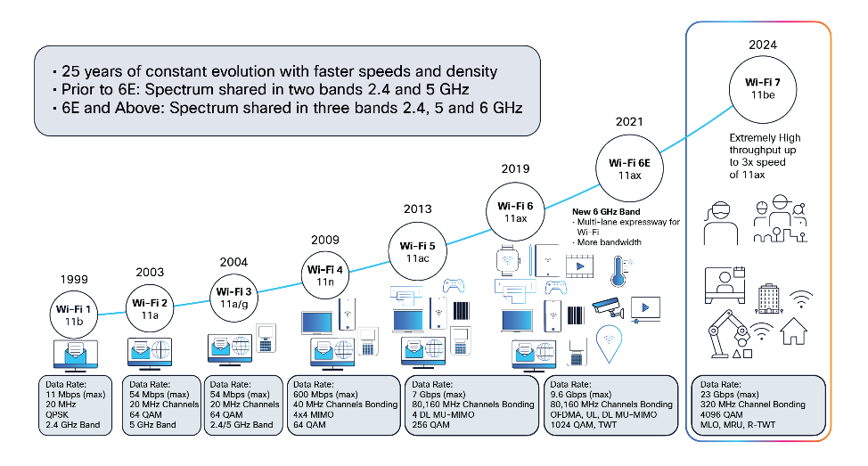
Wi-Fi evolution
Designing a cabling infrastructure that is cost-effective and scalable
It is important to recognize that the most cost-effective time to install structured cabling is during the initial construction or buildout phase of a building. Retrofitting cabling infrastructure after the construction is completed can result in significantly higher labor costs, project delays, and disruptions.
From a strategic planning perspective, cabling infrastructure not only should support current wireless demands but should be designed to accommodate emerging Wi-Fi technologies over the next 5, 10, or 15 years. As wireless technologies are evolving from Wi-Fi 5 (802.11ac) and Wi-Fi 6 (802.11ax) to Wi-Fi 7 (802.11be), both device density and throughput requirements are increasing rapidly, as are energy requirements. Therefore, structured cabling must be prepared to provide the best connectivity, with energy efficiency and EMI protection.
The following table shows the speed requirements and structured cabling alignment to fulfill the needs of each generation of Wi-Fi.
Table 3. Wi-Fi standards and cable requirements
|
|
Wi-Fi 4 |
Wi-Fi 5 |
Wi-Fi 6 |
Wi-Fi 6E |
Wi-Fi 7 |
Wi-Fi 8* |
| IEEE standard |
802.11n |
802.11ac |
802.11ax |
802.11ax |
802.11be |
802.11bn |
| Density of access points |
Low |
Medium |
High |
High |
Very high |
Ultra-high |
| Data rates |
450 Mbps |
1.2 Gbps |
2.5 Gbps |
5 Gbps |
10 Gbps |
10 Gbps |
| Category of cable |
Cat6 |
Cat6A |
Cat6A |
Cat6A |
Cat6A |
Cat6A |
To ensure a scalable and future-ready network infrastructure, structured cabling should be designed to:
● Support current and next-generation Wi-Fi data rates, including the higher throughput of Wi-Fi 7 and upcoming Wi-Fi 8.
● Enable flexible Moves, Adds, and Changes (MACs) to accommodate growing access point density.
● Prepare for scenarios in which each access point may require multiple multigigabit connections, especially in high-performance or mission-critical environments.
Cisco and Panduit value proposition
Cisco and Panduit have joined forces through an engineering alliance to accelerate the path to intelligent and future-ready workplaces. This collaboration harnesses the energy efficiency potential of intelligent buildings through the robust Panduit® structured cabling portfolio and the Cisco Catalyst™ platform for future workspaces. It will maximize the network infrastructure’s Return on Investment (ROI) through aligned architectures and optimized solutions from an ecosystem of trusted partners. The performance expectations of Wi‑Fi 7 require a physical layer designed around consistency, predictability, and standards of compliance. Infrastructure built on globally recognized standards provides a transparent and diagnosable environment, ensuring stable PoE delivery and reliable signal performance at scale.
For more than 25 years, Cisco and Panduit have collaborated to validate end‑to‑end architectures that align network electronics with high-quality, standards-compliant physical infrastructure. Solutions such as Panduit Vari‑MaTriX cable and all the Structured Cabling System designed by Panduit, are engineered to support Cisco’s advanced wireless platforms while preserving universal compatibility and operational simplicity. This jointly validated, standards-based approach ensures that enterprises can confidently adopt Wi‑Fi 7 knowing their infrastructure is optimized, open, and designed to evolve—making Cisco and Panduit the trusted foundation for next-generation wireless networks.

Cisco and Panduit engineering alliance
Cisco, a world-renowned leader in networking, has consistently been at the forefront of wireless innovation. Cisco’s contribution to Wi-Fi 7 includes the introduction of intelligent, secure, and assured Wi-Fi 7 access points that leverage AI-native technology to deliver enhanced wireless performance and user experiences. Key aspects of Cisco’s Wi-Fi 7 innovations are Intelligent Wireless, AI-enhanced radio resource management, AI-driven assurance, Cisco® Spaces, energy efficiency with power save mode, and power save insights. The company’s comprehensive portfolio of enterprise-class wireless solutions, combined with its end-to-end management and security capabilities, positions it as a key enabler of Wi-Fi 7 adoption.
Cisco’s Wi-Fi 7 access point portfolio
Cisco’s Wi-Fi 7 solutions are designed to address the evolving needs of businesses, educational institutions, healthcare providers, and industrial organizations.
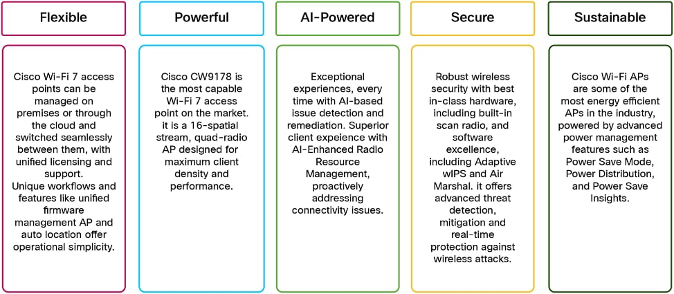
Qualities of Cisco Wi-Fi 7 access points
● Next-generation access points: Cisco’s Wi-Fi 7 access points leverage advanced radio designs and integrated antennas, supporting 2.4-GHz, 5-GHz, and 6-GHz bands and enabling seamless multilink operation.
● Cloud and on-premises management: Cisco Meraki® and Catalyst platforms offer unified network management, analytics, and automated troubleshooting, enhancing operational efficiency.
● Security and visibility: Cisco’s Catalyst Center, Identity Services Engine (ISE), and advanced threat protection deliver end-to-end security for Wi-Fi 7 environments.
● AI-driven optimization: Built-in artificial intelligence enables dynamic spectrum management, automatic power adjustments, and traffic prioritization for optimized user experiences.
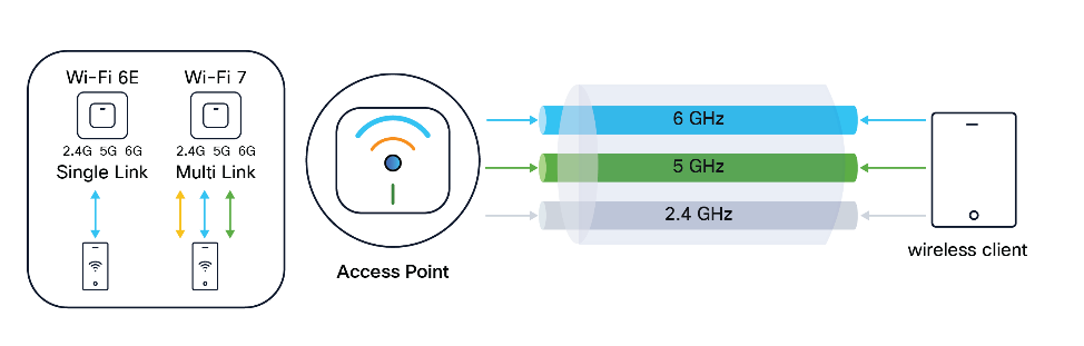
Wi-Fi 6E single link (2.4 or 5 or 6 GHz) vs Wi-Fi 7 Multi-Link Operation (MLO)
Cisco's Wi-Fi 7 access points are specifically engineered to meet diverse and evolving needs across a wide array of industries. These next-generation access points are ideal for demanding applications in businesses and corporate offices, providing seamless connectivity for employee productivity. They are also designed to support educational institutions, facilitating advanced learning experiences, and healthcare providers, helping ensure reliable and secure wireless infrastructure for critical operations. Furthermore, Cisco's Wi-Fi 7 solutions cater to industrial organizations, enabling automation and data-driven operations at scale, and are suitable for various public environments requiring high-performance wireless connectivity.
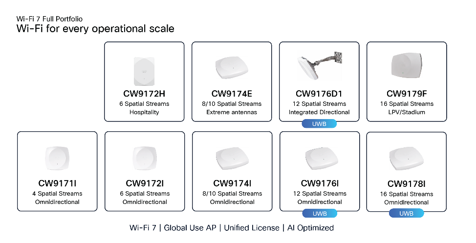
Cisco Wi-Fi 7 access point portfolio
Wi-Fi 7 brings unprecedented speeds and capacity, making non-blocking uplinks crucial to prevent bottlenecks and fully realize its potential. Without sufficient uplink bandwidth, the aggregated traffic from numerous high-speed Wi-Fi 7 clients can saturate the access point's connection to the network. This ensures that the advanced capabilities of Wi-Fi 7, such as multi-gigabit throughput and low latency, are not hindered by an inadequate backhaul connection. Besides data, higher PoE delivery under 802.3bt standards is also necessary to keep up with the demands of multiradio, multiband access points. Cisco’s Catalyst switching portfolio is specifically engineered to meet these rigorous physical and throughput requirements.
Equally critical is the choice of cabling. Older cable categories may work in the short term, but only Cat6A or higher provides the headroom to sustain multigigabit speeds while delivering high PoE loads over distance without signal loss or overheating. The wrong cable can quietly limit performance or shorten the life of a deployment, no matter how advanced the switch or access point is. “Wiring for wireless” highlights this fact: the long-term success of Wi-Fi 7 depends as much on selecting the right uplinks and copper as it does on the radios themselves.
The Role of Cisco switching in unleashing the full potential of Wi-Fi 7
Agile switching for building Wi-Fi 7
● The Cisco C9000 switches offer a versatile portfolio of fixed, modular, and compact fanless models designed to suit any deployment scenario. All Cisco C9000 Smart Switches with multigigabit ports support 2.5G and 5G speeds over standard Category 5e cables up to 100 meters, and 10G speeds over Category 6a cables up to 100 meters. While the IEEE 802.3bz standard limits cable reach to 100 meters, Cisco’s implementation also includes considerations such as limiting bundled cable length and patch cable length to maintain signal quality. These multigigabit PHYs can downshift speeds (e.g., from 5G to 2.5G or 1G) to maintain a stable connection over longer distances with Panduit’s Vari-MaTriX HD Cable Cat6. Cisco multigigabit switches support up to 60W PoE (Cisco UPOE), enabling the use of high-power devices while maintaining extended cable reach and high throughput.
The Cisco C9350 and C9610 are the new generation fixed access and modular core switches within the Cisco C9000 family, specifically designed for AI-ready enterprise networks and high-density Wi-Fi 7 deployments. Built on the Cisco Silicon One ASIC architecture, these switches provide up to 10 Gbps multigigabit downlinks and 90W UPOE+ to power modern IoT and wireless infrastructure. The C9350 features a high-performance StackWise-1.6T architecture and offer unified management through the Meraki Dashboard, Catalyst Center, or traditional CLI. Advanced security is a core focus, with hardware-ready support for post-quantum cryptography and Cisco Hypershield threat mitigation.
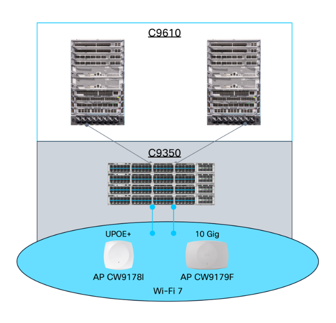
Cisco C9350 and C9610 Series Smart Switches
In the fixed access models the C9300X and C9350-48HX switches provide all-port non-blocking 10G speeds with up to 100G uplinks, the modular C9400 chassis scales massively to support up to 384 10G ports.
Meraki Dashboard and Catalyst Center
● Meraki Dashboard: Cisco Catalyst switches can be onboarded to the cloud-native Meraki Dashboard in two operational modes:
● Device Configuration: Provides real-time visibility and management flexibility, maintaining local configuration with cloud backup.
● Cloud Configuration: Enables full cloud-native configuration, firmware control, and troubleshooting, where the dashboard is the primary source of truth.
This integration offers a single-pane-of-glass experience for Catalyst 9200, 9300, 9500, and 9600 series hardware, streamlining hybrid network environments. By leveraging this cloud-first approach, organizations simplify IT operations and reduce the need for on-premises management servers.
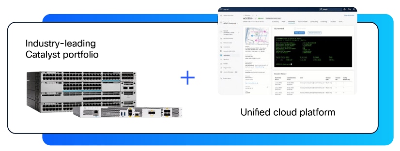
Cloud-managed and on-premises management
Catalyst Center: Designed for complex enterprise networks requiring deep automation and advanced telemetry. Catalyst Center enables full lifecycle configuration, granular segmentation, and SD-Access fabric deployment. It integrates tightly with Cisco ISE and ThousandEyes, delivering the orchestration required for Zero-Touch MACsec and high-availability operations.
Security and Visibility Enhancements with MACsec
MACsec (IEEE 802.1AE) provides hop-by-hop Layer 2 encryption, ensuring data confidentiality and integrity on wired Ethernet connections.
Cisco-to-Cisco MACsec Advantages: * Automatic Key Provisioning: Leveraging ISE and 802.1X for seamless key management.
● Hardware Acceleration: Line-rate encryption without throughput degradation.
● Future-Proof Protection: New Wi-Fi 7 and Catalyst 9000 integrations support Zero-Touch MACsec with Post-Quantum Cryptography (PQC), automatically securing the uplink between the switch and the Access Point against future quantum threats.
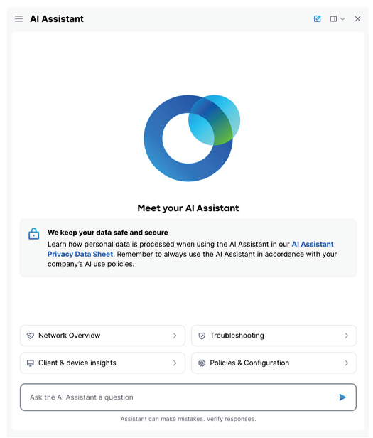
AI Assistant on Catalyst Center & Meraki Cloud
The new C9350 fixed access Switches support up to three AC/DC power supplies simultaneously per switch, providing ample budget for 90Watts of power and 10-Gbps speed at each port. This helps ensure the scalability and future-readiness of high-density office deployments.
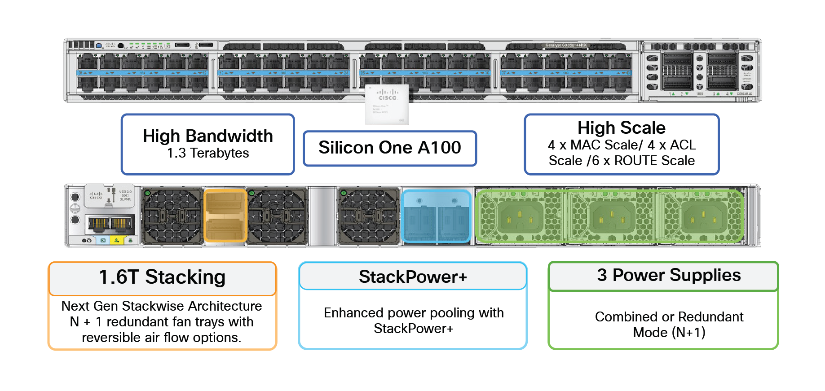
Advancements of C9350 smart switch
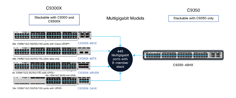
Catalyst 9300X and C9000 Smart Switch variants with UPOE+
The modular Cisco Catalyst 9400 Series switches enable a high density of PoE and access points by supporting up to 384 access ports with a choice of 10G, 5G, 2.5G multigigabit copper, 1G copper, Cisco UPOE+ (90W), UPOE (60W), and PoE+ (30W) simultaneously across the system. It offers delivery of up to 90W per port with IEEE 802.3bt PoE standards, to power high-demand devices like Wi-Fi 7 access points. Advanced supervisor engines provide high bandwidth per slot (up to 480 Gbps) and support 100G uplinks for aggregation, helping ensure nonblocking performance for dense deployments.
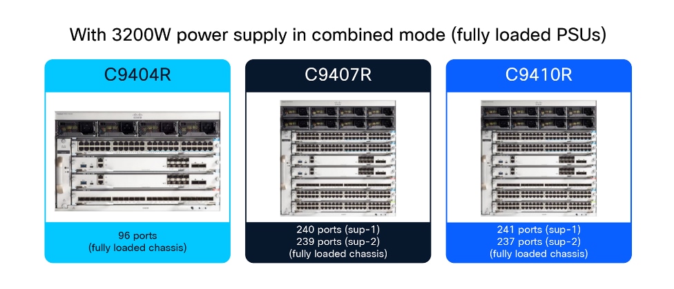
Modular switches
Power Savings and sustainab`ility with energy management
The C9000 Smart Switches are enabled with power telemetry to provide real-time, detailed data on the power consumption of the system and their connected devices. This telemetry data includes metrics like total power draw, power consumption per switch port, and PoE usage.
Visibility into the energy usage and sustainability metrics of a network and its connected devices can be seen in the Cisco Catalyst Center PoE Assurance dashboard and the Energy Management dashboard, available on both Catalyst Center and the Meraki dashboard. The dashboards are also integrated with an Energy Management Capability API, which provides site-specific information:
● Carbon intensity
● Total Greenhouse Gas (GHG) emissions
● Energy mix
● Energy cost
Cisco Energy Management dashboards offer a comprehensive solution to monitor, analyze, and optimize energy consumption across IT and facility resources, helping organizations achieve cost savings and meet sustainability targets.
Cisco access points operated either in cloud or on-premises controller mode offer power savings features such as port scheduling to turn off access points during periods of low demand to reduce power use.
The on-premises controllers offer power profiles to turn off components of specific radios on access points to conserve energy.

Port power schedules on Meraki cloud
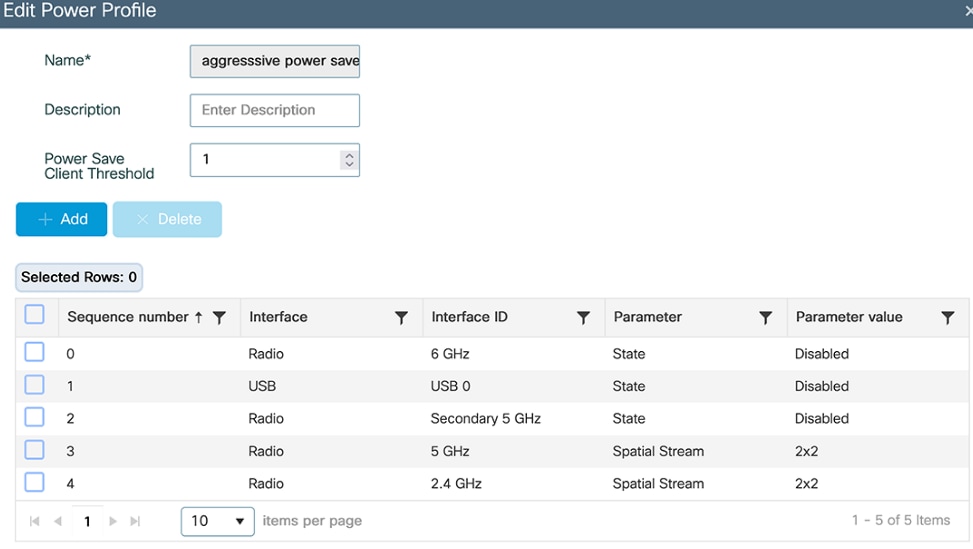
Editing a power profile on C9800 wireless controller UI
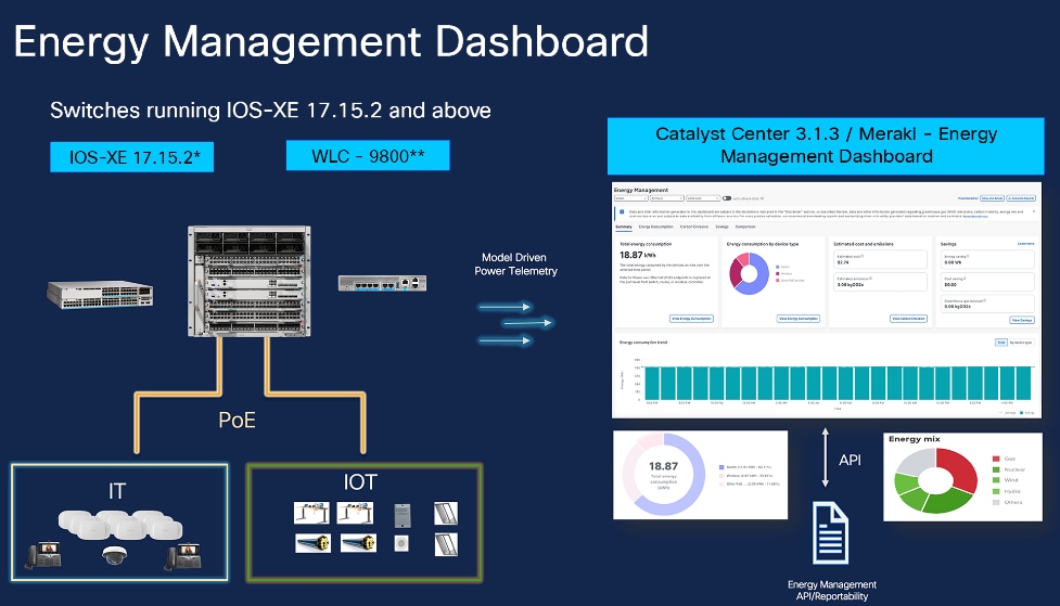
Energy Management Dashboard with Catalyst Center and Meraki cloud
High availability for mission-critical wireless
High availability is embedded into each and every layer of the data links both physically and logically, Cisco Wi Fi 7 APs such as the CW9178I and Meraki MR57 include dual multigigabit RJ 45 ports with LACP for up to 10 Gbps aggregated throughput, PoE redundancy, and support for both single homed and dual homed topologies. The CW9178I requires 802.3bt and supports dual PoE inputs for power failover, while the MR57 can combine power from two PoE sources to achieve higher power budgets. With MLAG (Multi-Chassis Link Aggregation Group), these PoE powered APs can complete software upgrades in under 3 seconds while maintaining power, reflecting Wi Fi’s evolution into a utility grade service for high density, AI driven campus networks.
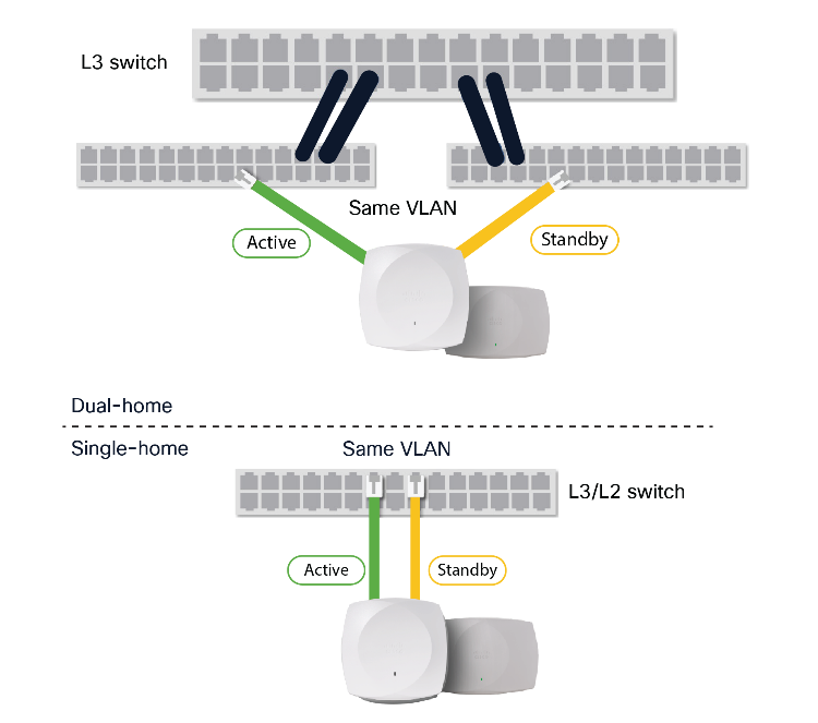
Dual Ethernet Port Topologies
In mission critical environments like hospital operating rooms, certain Wi Fi access points use dual Ethernet ports to provide both uplink and power resiliency, ensuring continued operation even if a switch fails. Most enterprise deployments, however, rely on a salt and pepper design, where alternating APs connect to different switches so RF coverage remains intact during a switch outage and when at switchport level the Catalyst and C9000 switches support Perpetual PoE, Fast PoE, and 2-event detection to recover, restore, and reconnect the endpoints in the event of power failures or unplanned disconnects.
Switch and PoE Power resiliency
Cisco StackPower revolutionizes power resiliency by aggregating up to four switches into a single, shared energy pool. By treating the total capacity of all power supplies as a unified resource, it ensures high availability for both the switches and connected PoE endpoints. Operating over dedicated StackPower cables, StackPower functions in a ring topology to maximize redundancy. While enabled by default for immediate impact, it allows for flexible deployment in either power-sharing or redundant modes, ensuring that critical devices remain online even during power supply failures."
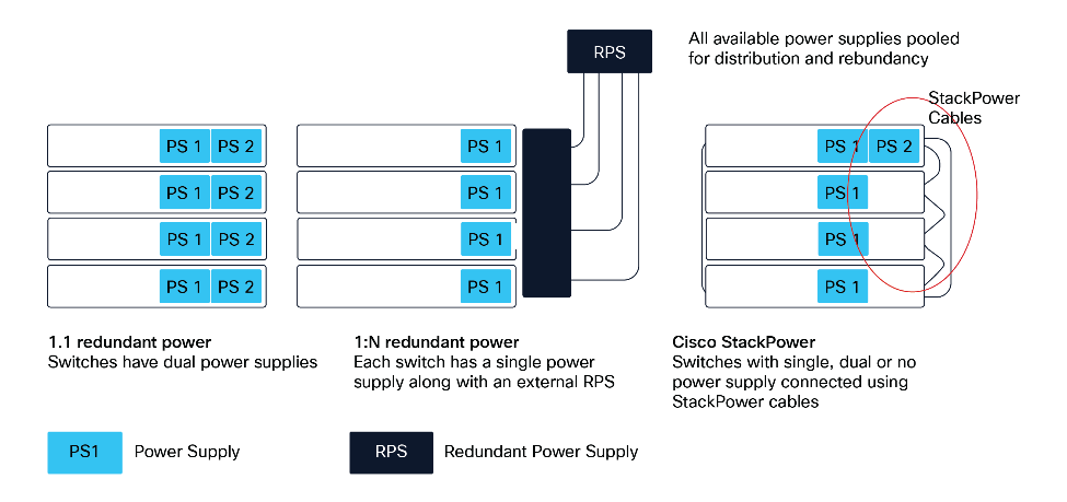
Strategies for power sharing and power redundancy
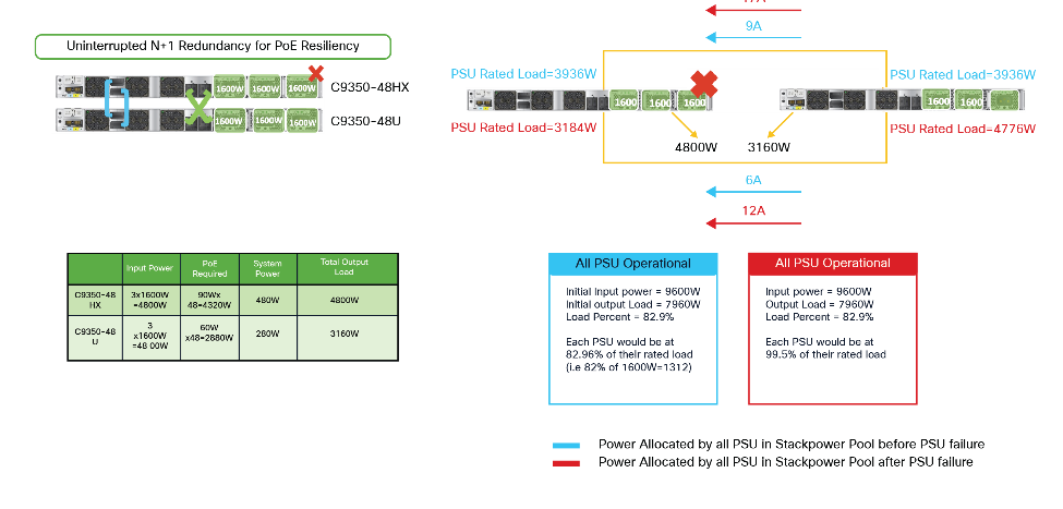
New StackPower+ example
Advanced PoE Technologies for uninterrupted power
To maximize the uptime of critical Wi-Fi 7 deployments, Cisco Perpetual PoE maintains uninterrupted power to access points during switch upgrades, ensuring continuous connectivity for critical wireless clients. This resilience is reinforced by Fast PoE and hardware-based 2-Event classification, which instantly negotiate and deliver the high wattage required by advanced Wi-Fi 7 radios immediately upon boot, bypassing the delays of software-based negotiation. Together, these features guarantee that high-speed wireless infrastructure remains operational and responsive, even during maintenance windows or power restoration events.
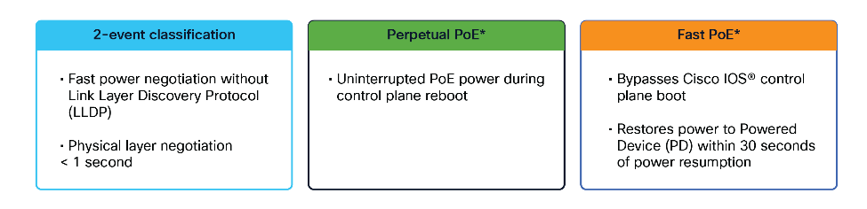
Advanced PoE High availability features
The C9300 and C9350, are developed to support mission-critical wireless services with features like Extended Fast Software Upgrade (xFSU), which can upgrade the switch in less than 3 seconds and potentially in subsecond times, helping ensure that the Control and Provisioning of Wireless Access Points (CAPWAP) protocol retains control, that data traffic is undisrupted, and that there is zero impact to the wireless user experience. Similarly, the modular Catalyst 9400 Series supports In-Service Software Upgrade (ISSU), enabling software upgrades without interrupting network traffic, thus maintaining 100% uptime during the process. ISSU is available on switches with StackWise® Virtual or dual supervisor modules.
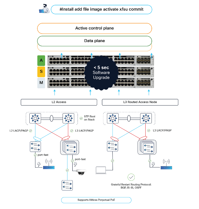
Extended Fast software upgrade
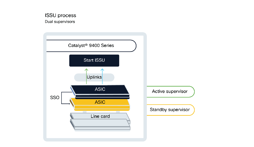
ISSU process with dual supervisors
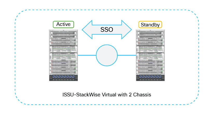
ISSU with StackWise Virtual
Catalyst 9800 high availability
The Cisco Catalyst 9800 Series Wireless Controllers offer robust High Availability (HA) features designed to help ensure network resilience, minimize downtime during both unplanned outages and planned maintenance, and provide a seamless experience for wireless clients.
The primary options for high availability are Stateful Switchover (SSO) and N+1 redundancy.
High availability Stateful Switchover (SSO).
SSO is the most comprehensive HA solution, providing a "hot standby" model for near-instantaneous recovery.
N+1 redundancy
N+1 redundancy is a "cold standby" model that provides a cost-effective backup solution for multiple primary controllers.
Table 4. Comparison of SSO and N+1 redundancy
| Feature |
SSO |
N+1 redundancy |
| Model |
1 active, 1 hot standby (1:1) |
1 cold standby for N actives |
| Failover time |
Subsecond |
Tens of minutes |
| Client impact |
No client disconnection |
Clients disconnect and must reconnect |
| Access point impact |
Access points remain connected |
Access points reboot and rejoin backup |
| Use case |
Mission-critical environments |
Less-critical environments, cost savings |
Software resiliency and hitless upgrades
The Catalyst 9800 Series architecture, particularly when deployed in an SSO pair, enables significant uptime during software maintenance.
● ISSU: Allows software upgrades to occur on an SSO pair with minimal downtime. The process involves upgrading the standby controller first, forcing a stateful switchover so it becomes active, and then upgrading the formerly active unit. This helps ensure that the wireless network remains operational throughout the upgrade cycle.
● Software Maintenance Updates (SMU): Software patches that can be applied to fix specific issues.
◦ Hot patching: Minor patches can be applied without rebooting the controller, resulting in zero downtime.
◦ Cold patching: Patches that require a reboot can be applied hitlessly on an SSO pair using the ISSU process.
● Rolling access point upgrades: To prevent widespread disruption during access point software updates, the controller can perform rolling upgrades. It intelligently upgrades a subset of access points at a time, ensuring that an access point’s neighbors are not rebooted simultaneously, which allows clients to seamlessly roam to an adjacent access point.
The Role of Panduit in Wi-Fi 7
Panduit is a global leader in physical infrastructure, specializing in end-to-end cabling infrastructure and network connectivity solutions. The higher speeds and capacity delivered by Wi-Fi 7 make supporting physical infrastructure even more critical to realize its full benefits.
Panduit Wi-Fi 7-ready infrastructure
Panduit offers a comprehensive suite of products tailored for Wi-Fi 7 deployments:
● High-performance cabling: Category 6A and beyond, including shielded and unshielded twisted pair cables, supports the higher data rates and PoE requirements of Wi-Fi 7 access points.
● Optimized pathways and racks: Innovative pathway designs enable efficient airflow and cable management, helping maintain signal integrity and minimizing downtime.
● Field-terminated connectors streamline installation and maintenance, reducing deployment time and costs.
● Reliable power delivery: Support for higher PoE levels helps ensure that access points and associated devices receive consistent, reliable power without the need for expensive electrical upgrades.
Panduit has developed a new generation of Cat6A cable called Vari-MaTriX HD, which offers significant advantages in terms of reduced size and performance that exceeds industry standards. It features 23 AWG copper and incorporates various Panduit innovations, making it a cost-effective, flexible, and eco-friendly option for network cabling installation.
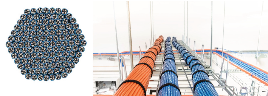
Cross section of a Panduit Vari-MaTriX cable
The Panduit TX6A Vari-MaTriX HD cable, with an outer diameter of just 0.230 inch (5.8 mm), is the smallest 23 AWG Cat6A UTP cable available. It supports Ethernet speeds from 1G to 10G without compromising reliability. Companies upgrading from Cat6 can usually retain current cable management systems and cable fill ratios.
Panduit’s TX6A Vari-MaTriX HD cable uses a unique Vari-MaTriX technology that helps reduce two major types of signal interference:
Alien crosstalk: Interference from nearby cables in the same bundle.

● ElectroMagnetic Interference (EMI) caused by electrical noise
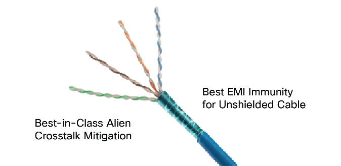
Vari-MaTriX technology for reducing signal interference
The cable includes a special metal tape that wraps around all four wire pairs. Unlike traditional shielding, this tape is made of segments of different lengths, which helps block interference while using less space inside the cable. Thanks to this design, the cable not only meets Cat6A performance standards, but also maintains a smaller diameter, making it the smallest 23 AWG Cat6A UTP cable available today.
The Panduit TX6A Vari-MaTriX HD cable is fully compatible with PoE (IEEE 802.3af), PoE+ (802.3at), and PoE++ (802.3bt Type 3 and 4). It is built to operate at high temperatures—up to 75°C (167°F), making it ideal for handling the heat generated by high-power PoE.
Thanks to its slim design, this cable can dissipate heat more efficiently than larger or older cables. This helps reduce the chances of signal loss or overheating and lowers the risk of fire hazards in dense cable bundles.
With this advanced heat performance, the TX6A Vari-MaTriX HD is a smart choice for modern buildings where many Cat6A cables are needed to support high network traffic and PoE-powered IoT devices across multiple locations.

The Panduit TX6A Vari-MaTriX HD cable is the smallest 23 AWG Cat6A UTP cable in the world, which means it requires less raw material during manufacturing—offering both environmental and cost benefits. Its compact size also enables the use of existing Cat6 cable management systems in many projects, allowing organizations to reuse infrastructure or route more cables through the same pathways, reducing the need for additional hardware and resulting in a smaller carbon footprint in structured cabling installations. Environmental Product Declarations (EPDs) can be provided by Panduit products.
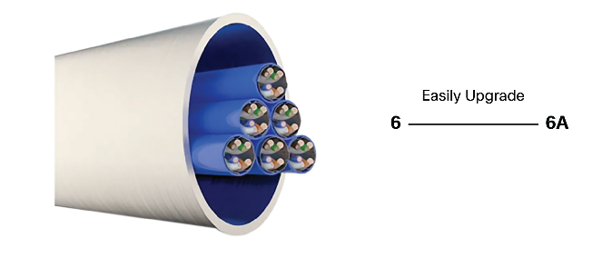
Easily upgrade from Cat6 to Cat6A
In addition, the cable supports 1G to 10G and is fully compliant with Cat6A performance standards, including UPOE+ (IEEE 802.3bt). This makes it a highly future-ready solution, capable of powering next-generation devices that demand higher bandwidth and power—without the need to upgrade or replace the cabling and enabling reuse of the existing pathways.
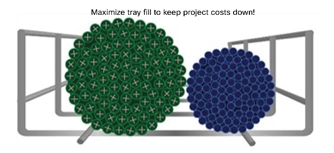
Thinner cables can keep project costs down
Why is cable thinness important? Mainly because thinner cables are easier to install, are lighter to transport and handle, are more flexible, with a greater bending range, and aid in the transition from Cat6 to Cat6A due to their space-saving dimensions and the use of the same installed conduit.
Table 5. Space-saving benefits of Panduit Vari-MaTriX HD cable
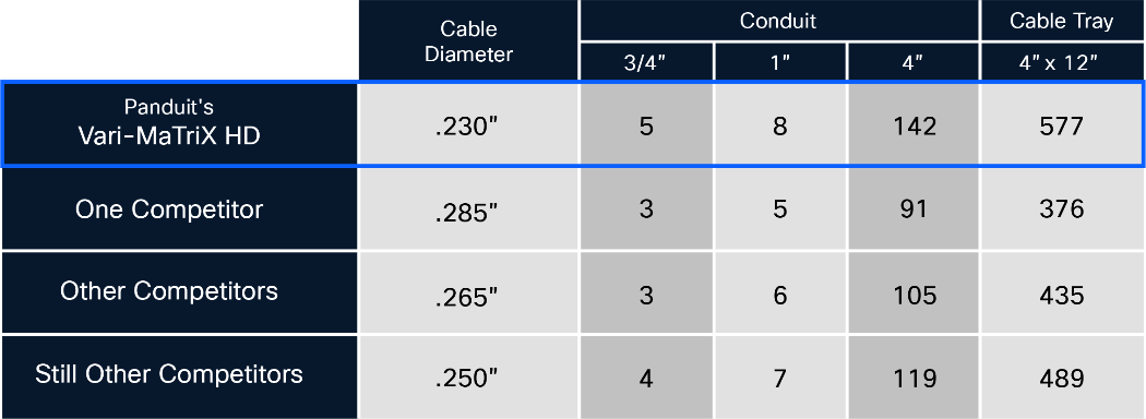
The table illustrates the advantages of using Panduit Vari-MaTriX HD by comparing the number of cables from Panduit and its competitors that can fit into different conduit tubes or trays. The smaller size of Panduit’s cable makes it more effective for any structured cabling upgrade.
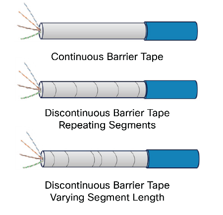
Approaches to barrier taping
The innovative design of Panduit Vari-MaTriX HD provides greater protection against electromagnetic interference in UTP cables. This is one of the unique value propositions from Panduit in this offering. This barrier eliminates the resonance associated with interference through cuts in different segments.

Panduit Vari-MaTriX foil tape
Panduit Mini-Com® TX6A™ PLUS Jack Modules: Multi-Gig Ready!
For the most demanding applications, the Mini-Com Copper Cabling System is designed to provide the most innovative features and the lowest cost of ownership over the life of your network. We strive to provide the perfect solution for any application, which means offering custom cable assemblies, a wide range of colors and lengths, and a large selection of patch panel and faceplate types to suit your needs.
Wi-Fi 7 deployments demand high-performance infrastructure to support your business goals. Choose the Mini-Com Copper Cabling System for unmatched performance, quality, and innovation—purpose-built to enable the latest technologies. Unlock a 25-year system warranty with an end-to-end Mini-Com solution.
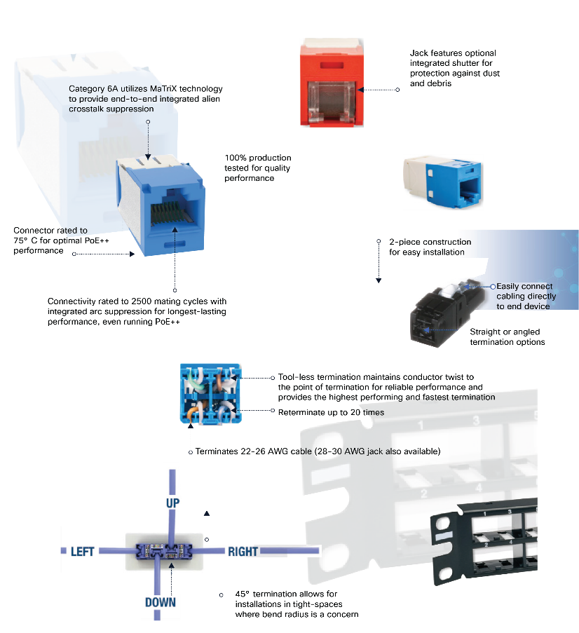
This image illustrates the assembly and cable management of a modular network connectivity system
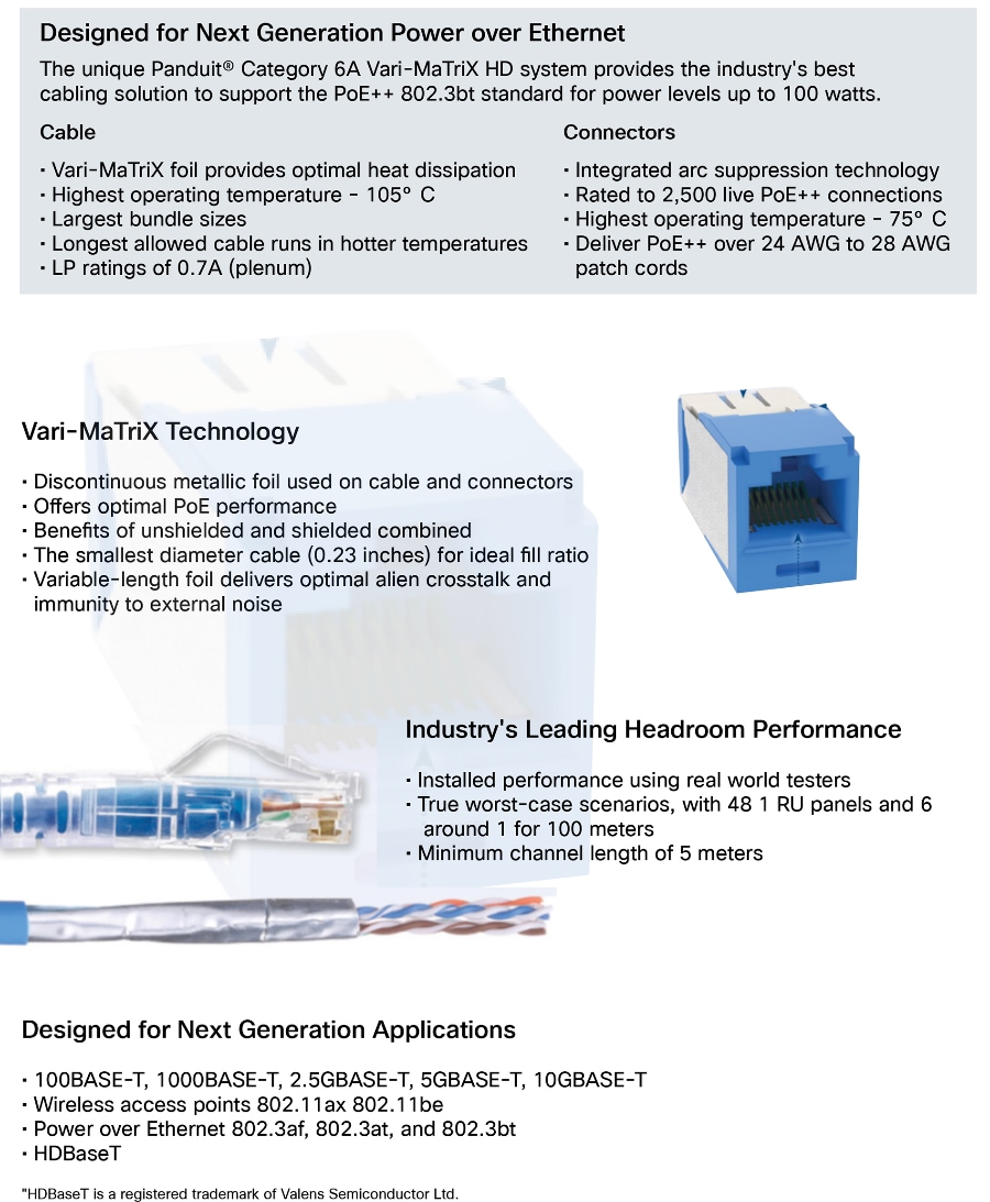
This image illustrates the assembly and cable management of a modular network connectivity system
Panduit’s Wi-Fi 7-ready infrastructure: The architecture
The design of smart buildings is undergoing a transformation to reduce their carbon footprint and support organizations’ sustainability goals.
Therefore, the following reference architectures have been developed to provide companies with options for designing their physical network infrastructure with greater resilience, flexibility, efficiency, and sustainability.
Architecture # 1: Traditional telecommunications room
This is a traditional architecture in which network equipment such as Cisco switches are typically located in a telecommunications room and installed in a 4-post rack. From there, the PoE connections for the access points are distributed. This room houses Uninterruptible Power Supplies (UPSs) and Power Distribution Units (PDUs) connected to Cisco switches, which can be independent, stacked, or in a chassis with different cards for greater scalability.
A telecommunications room schematic and 4-post rack
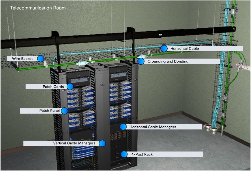
Infrastructure for a Telecommunications Room
Architecture # 2: Edge enclosures to save space
This architecture integrates Panduit TrueEdge enclosures to save space and provide greater flexibility and scalability in integrating Cisco switches and PoE connections for access points. It offers many advantages, including:
● Space savings: It does not require a telecommunications room or building space.
● Greater versatility: It can be installed in a strategic location and does not require a specific space on a specific floor.
● Energy savings: The enclosures have a special fan system that allows the same air circulating in the office or corporate space to be used, without requiring a separate air conditioning system.
● Cisco switches can be installed to deploy Wi-Fi 7 installations with greater versatility.
● They are an extraordinary element for maintaining the redundancy and resilience of the organization’s Wi-Fi environment.
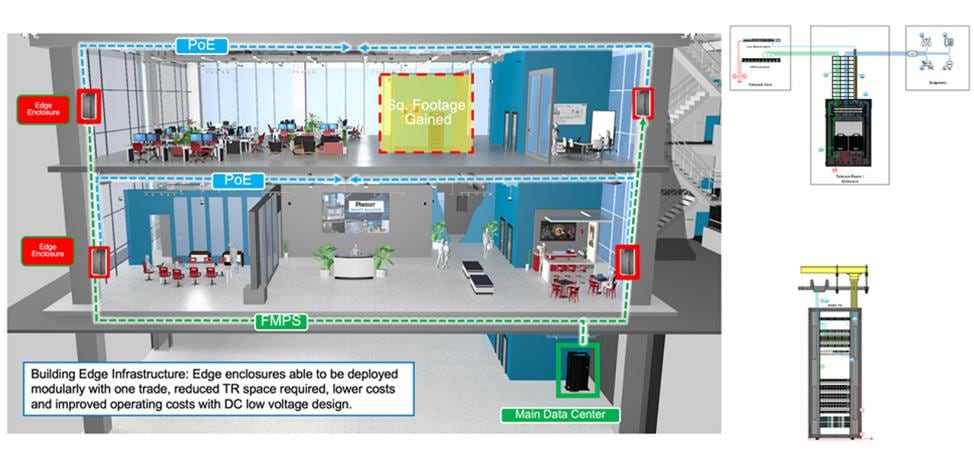
Edge Architecture for Telecommunications Rooms
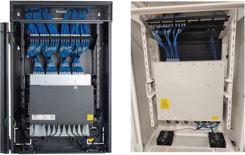
Cisco Catalyst 9300 deployed in Panduit TrueEdge
The RapidID™ is an automated network mapping system that replaces labor-intensive, error-prone cable documentation with a fast, accurate solution. Using pre-labeled patch cords and barcode scanner (Bluetooth or wired), RapidID captures cable data in real-time, dramatically reducing manual effort and eliminating human errors. Ideal for data centers, telecom rooms, multi-tenant infrastructures, RapidID is designed to save time and keep your network running smoothly.
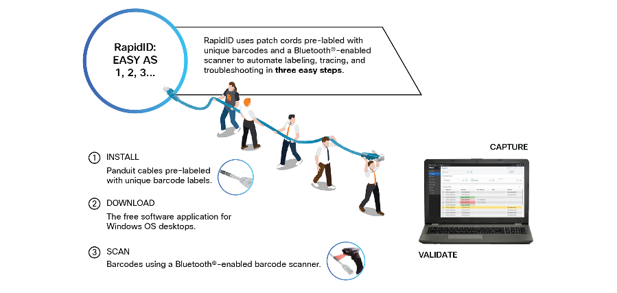
RapidID solution, which automates network cable management—including labeling, tracing, and troubleshooting—through a simple three-step process
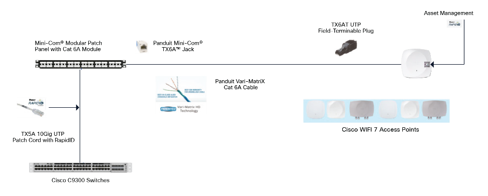
End to End WiFi-7 readiness
Connection for next-generation Wi-Fi 7 access points
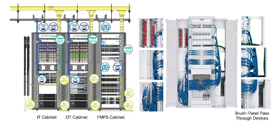
The new generation of Wi-Fi 7 access points require not only greater speed, bandwidth, and power, but also greater resilience as a mission-critical technology for organizations. Businesses today rely entirely on wireless connections to perform routine tasks, hold meetings, and connect to critical applications. Therefore, the new generation of Wi-Fi 7 access points feature dual-port configurations for link aggregation.
To support this next generation, we present the following architecture, evolving the way wireless environments are designed today.
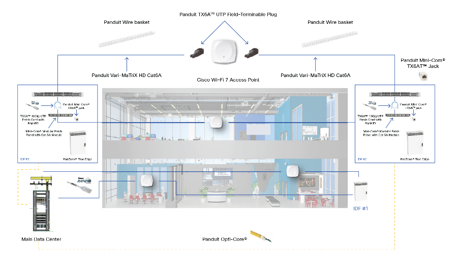
Smart building architecture for Wi-Fi 7 between Cisco and Panduit
Panduit Infrastructure Product Details
| Type |
Panduit part description |
Part Number |
| Unshielded |
24 - Port Patch Panel |
CPP24FMWBLY |
| 48 - Port Patch Panel |
CPP48FMWBLY |
|
| Cat 6A Jack Module |
CJ6X88TGBU |
|
| Cat 6a Patch Cord |
UTP28X3MBU |
|
| Cat 6A Flame Rated Patch Cord |
Depends on region, see Table 8 Panduit copper flame-rated patch cords |
|
| Cat 6A Horizontal Cable |
Depends on region, see Table 8 Panduit copper flame-rated patch cords |
|
| Angled TX6A Field Term Plug |
FP6X88MTG |
| Type |
Panduit part description |
Part Number |
| Shielded |
24 - Port Patch Panel |
CP24BLY |
| 48 - Port Patch Panel |
CP48BLY |
|
| Cat 6A Jack Module |
CJS6X88TGY |
|
| Cat 6a Patch Cord |
STP28X3MBU |
|
| Cat 6A Flame Rated Patch Cord |
Depends on region, see Table 8 Panduit copper flame-rated patch cords |
|
| Cat 6A Horizontal Cable |
Depends on region, see Table 8 Panduit copper flame-rated patch cords |
|
| Angled TX6A Field Term Plug |
FPS6X88MTG |
| Type |
Panduit part description |
Part Number |
| Enclosure and Rack |
TrueEdge Wall Mount Cabinet |
WME6WH |
| Adjustable Depth 4-Post Rack |
AR4PCNWH |
|
| PatchRunner™ 2 Vertical Manager |
PR2VSD12WH |
|
| PatchRunner™ 2 Enhanced Vertical Manager |
PE2VSD1296WH |
|
| PatchRunner™ 2 Horizontal Manager |
PR2HF2WH |
|
| Wire Basket Tray |
PWB4X18WH |
|
| FiberRunner® 12" x 4" Hinged Channel |
FR12X4LYL2 |
Table 6. Panduit parts used in the Wi-Fi 7 deployment with the Catalyst 9300 Series Switch
| Type |
Panduit part description |
Part Number |
| Unshielded |
24-Port Patch Panel |
CPP24FMWBLY |
| Cat 6A Jack Module |
CJ6X88TGBU |
|
| Cat 6A Patch Cord |
UTP28X3BU |
|
| Cat 6A Flame Rated Patch Cord |
Depends on region, see Table 9: Panduit copper flame-rated patch cords |
|
| Cat 6A Horizontal Cable |
Depends on region, see Table 9: Panduit copper horizontal cables |
|
| TX6A Field Terminable Plug |
Straight: FP6X88MTG / Angled: FPUD6X88MTG |
|
| Shielded |
24-Port Patch Panel |
CP24BLY |
| Cat 6A Jack Module |
CJS6X88TGY |
|
| Cat 6A Patch Cord |
STP28X3MBU |
|
| Cat 6A Flame Rated Patch Cord |
Depends on region, see Table 7: Panduit copper flame-rated patch cords |
|
| Cat 6A Horizontal Cable |
Depends on region, see Table 7: Panduit copper horizontal cables |
|
| TX6A Field Terminable Plug |
Straight: FPS6X88MTG |
Table 7. Cisco parts used in the Wi-Fi 7 deployment with the Catalyst 9300 Series switch
| Type |
Part Number |
| Catalyst 9300 Series Switches |
C9300 Multigig Switches |
| Catalyst Access Points |
CW9171, CW9172, CW9174, CW9176, CW9178 |
| Type |
Panduit part description |
Part Number |
| Unshielded |
24-Port Patch Panel |
CPP24FMWBLY |
| Cat 6A Jack Module |
CJ6X88TGBU |
|
| Cat 6A Patch Cord |
UTP28X3BU |
|
| Cat 6A Flame Rated Patch Cord |
Depends on region, see Table 8: Panduit copper flame-rated patch cords |
|
| Cat 6A Horizontal Cable |
Depends on region, see Table 8: Panduit copper horizontal cables |
|
| TX6A Field Terminable Plug |
Straight: FP6X88MTG / Angled: FPUD6X88MTG |
|
| Shielded |
24-Port Patch Panel |
CP24BLY |
| Cat 6A Jack Module |
CJS6X88TGY |
|
| Cat 6A Patch Cord |
STP28X3MBU |
|
| Cat 6A Flame Rated Patch Cord |
Depends on region, see Table 8: Panduit copper flame-rated patch cords |
|
| Cat 6A Horizontal Cable |
Depends on region, see Table 8: Panduit copper horizontal cables |
|
| TX6A Field Terminable Plug |
Straight: FPS6X88MTG |
Table 8. Panduit copper horizontal cables
| Flame Rating |
Category 6A Cable |
|
| Unshielded |
Shielded |
|
| Plenum (CMP) |
PUP6AHD04BU-G |
PFP6X04BU-UGZ |
| Riser (CMR) |
PUR6AHD04BU-G |
PFR6X04BU-CGZ |
| CM |
PUC6AHD04BU-EG |
PFR6X04BU-CGZ |
| Euroclass CCA |
PUY6AHD04WH-EG |
PFY6X04WH-CED |
| Euroclass B2CA |
PUK6AHD04WH-EG |
PFFW6X04WH-KED |
| LSZH |
PUL6AHD04WH-EG |
PFL6X04WH-CEG |
This is a traditional architecture, in which network equipment such as Cisco switches are typically located in a telecommunications room and installed in a 4-post rack. From there, the PoE connections for the access points are distributed. This room houses UPSs and PDUs connected to Cisco switches, which can be independent, stacked, or in a chassis with different cards for greater scalability.
FMPS overview: The future of safe and efficient energy in smart buildings
We are at a pivotal moment in infrastructure development: DC power systems are set to replace traditional AC infrastructure in many commercial buildings. This transition promises significant benefits, including energy savings and improved digital power control. Additionally, DC power distribution naturally aligns with renewable energy sources and energy storage systems, which inherently generate or store DC power. As renewable energy costs continue to decrease, reaching or surpassing grid parity in many areas, the synergy between DC power distribution and clean energy sources is set to transform how we power and manage modern commercial buildings. Cisco has led the development of PoE for two decades, establishing it as the primary remote powering technology for networked devices.
Cisco and Panduit have joined forces to introduce a groundbreaking DC power distribution solution for smart buildings and the broader enterprise networking market. This collaboration brings together two industry-leading technologies, Cisco's Catalyst 9200 and 9300 PoE switching platforms and Panduit's UL4000-certified Fault Managed Power System.
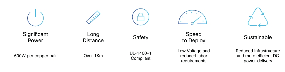
Benefits of Panduit’s Fault Managed Power System
Panduit Fault Managed Power System
The Panduit Fault Managed Power System (FMPS) is a versatile remote power delivery solution that enables systems integrators to safely and efficiently power Cisco Catalyst 9300 Series Switches across various deployment scenarios. Whether implemented as a DC-only power source or as a centralized backup DC power solution, the FMPS creates the first Cisco standardized end-to-end DC power distribution system. This innovative approach offers flexibility and reliability in powering network infrastructure.
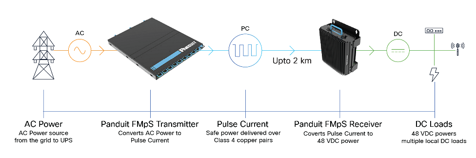
Panduit Fault Managed Power System
How does FMPS work?
The Panduit FMPS innovatively delivers power through a pulse current waveform. This method uses short-duration pulses, typically lasting 3 milliseconds, to transmit electricity. By employing this pulsed approach, the system can rapidly detect potentially hazardous faults, such as line-to-earth or line-to-arc conditions that pose shock and fire risks. Upon detection, the FMPS can halt power transmission almost instantaneously, significantly enhancing safety and reducing potential damage.
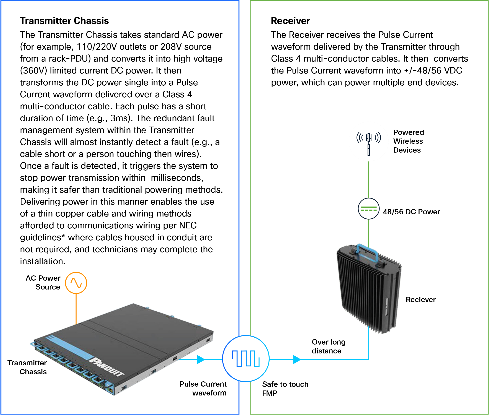
The Panduit FMPS at a glance
FMPS centralized power architecture
A recommended practice by Panduit for the FMPS is to centralize the power delivery architecture in a few physical locations and to limit the square footage throughout a floor. The FMPS enables this recommendation by permitting devices to be deployed at remote sites a considerable distance away. The remote sites will then converge to the FMPS in the center of the deployment.
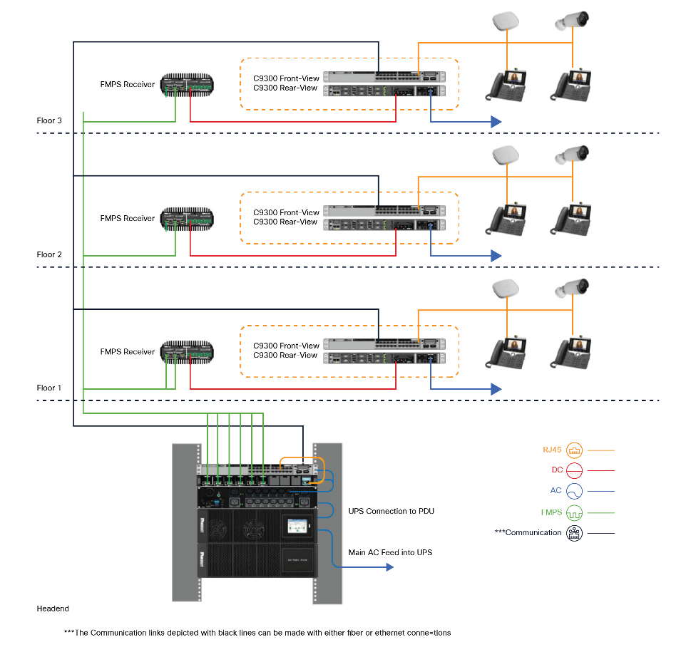
The FMPS across several floors of a building

For more information, visit https://www.cisco.com and https://www.panduit.com.
● Wireless Site Survey: Ensure that the wireless design supports 6 GHz spectrum, while also considering new requirements for activity based work, modern business applications and location based services.
● Infrastructure Audit: Confirm that all new horizontal cabling is Category 6A (Vari-MaTriX) to support 10Gbps throughput and mitigate alien crosstalk.
● Power Budgeting: Calculate the total POE requirements for all APs. If runs exceed 100m or centralized power is preferred, evaluate Panduit FMPS implementation.
● Switch Resiliency: Configure StackPower+ on Catalyst 9350 switches to create a shared energy pool, ensuring N+1 power redundancy.
● High Availability: Enable Stateful Switchover (SSO) on Cisco Wireless 9800 Controllers and Extended Fast Software Upgrade (xFSU) on access switches to maintain 100% uptime.
● Conduit/Tray Fill: Verify that cable bundle sizes remain within recommended fill ratios to prevent thermal degradation of the copper pairs.
● Energy Telemetry: Integrate the Catalyst Center or Dashboard and Cisco Spaces with your Building Management System (BMS) to monitor real-time carbon intensity and energy consumption, and space utilization.
● Validation: Perform end-to-end certification testing using industry-standard testers to ensure compliance with ANSI/BICSI 007-2024 standards.
Wi-Fi 7 marks a pivotal leap forward in wireless technology, supporting the next generation of digital experiences. Cisco’s best-in-class wireless solutions, coupled with Panduit’s future-ready physical infrastructure, empower organizations to deliver high-performance, reliable, and secure networks. By working together, these industry leaders ensure that enterprises can meet the demands of today—and tomorrow—with confidence.