Cisco C9610 Series Smart Switches Architecture
Available Languages
Bias-Free Language
The documentation set for this product strives to use bias-free language. For the purposes of this documentation set, bias-free is defined as language that does not imply discrimination based on age, disability, gender, racial identity, ethnic identity, sexual orientation, socioeconomic status, and intersectionality. Exceptions may be present in the documentation due to language that is hardcoded in the user interfaces of the product software, language used based on RFP documentation, or language that is used by a referenced third-party product. Learn more about how Cisco is using Inclusive Language.
As enterprise networks evolve to meet the demands of AI‑driven workloads, security threats, and hybrid operations, the modern campus core infrastructure must deliver uncompromising scale, flexibility, and defense. The Cisco® C9610 Series Smart Switches serve as Cisco's next-generation modular campus core platform, designed to power the AI enterprise with unmatched density and performance, starting today and continuing into the future.
Supporting high-density 25/50 GE and 40/100 GE, along with 400 GE, for tomorrow's demands, the C9610 Series blends modular scalability, silicon‑powered programmability, and security‑first architecture. Built around Cisco Silicon One™ K100 and E100 Application-Specific Integrated Circuits (ASICs), the Cisco C9610 Series Supervisor Engine 3 and 3 XL (Supervisor 3/XL) can deliver throughput up to 51.2 Tbps (25.6 Tbps full duplex) per chassis and 6.4 Tbps ( 3.2 Tbps full duplex) per slot, with fully redundant supervisors to provide high availability and true operational resilience.
The Cisco C9610 Series Smart Switches are network switches equipped with additional processing resources, such as multicore CPUs, dedicated RAM, and Solid-State (SSD) storage, that enable them to host applications locally on the device. This capability allows the Cisco C9610 Series to support advanced functions like network services (such as ThousandEyes® agents) , security enforcement (such as firewall agents), and AI workloads directly on the switch without relying on external servers or cloud resources. The switches are also designed for unified operations across on-premises, cloud, and hybrid deployments. They enable simplified licensing, consistent support, and seamless manageability across Cisco Meraki™ or Catalyst® management platforms.
This white paper presents a comprehensive architectural overview of the Cisco C9610 Series chassis, covering system design, power and cooling architecture, storage configurations, and detailed insights into the Supervisor 3/XL module and compatible line cards.
The Cisco C9610 Series platform is a modular switch based on the Cisco Silicon One E100 ASIC (Supervisor 3) or K100 (Supervisor 3 XL) ASIC, which provides greater scale and higher throughput (Figure 1) while also protecting your existing investments. The platform runs on the modern open Cisco IOS® XE operating system, which supports model-driven programmability, has the capacity to host containers with support for up to 960 GB of SSD storage, and can run third-party applications and scripts natively within the switch (by virtue of the x86 CPU architecture, local storage, and a larger memory footprint).
The Cisco IOS XE operating system offers enhanced high availability features such as Stateful Switchover (SSO), Software Maintenance Upgrades (SMU), In-Service Software Upgrade (ISSU), Graceful Insertion and Removal (GIR), and Cisco StackWise® Virtual technology. Improved high availability is also added via Titanium/Platinum-efficient redundant power supplies as well as variable-speed, highly efficient redundant fans.
Cisco C9610 Series
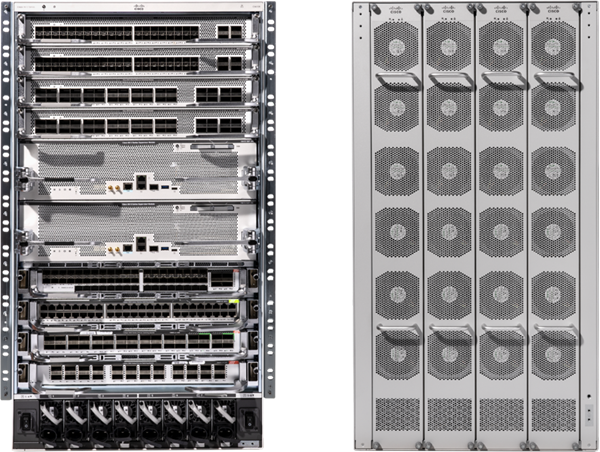
The Cisco C9610R is a 10-slot modular chassis. Two middle slots (slots 5 and 6) are dedicated for supervisors only and work in SSO mode. The remaining eight slots, four on the top and four on the bottom, are for line cards. The chassis is designed to provide up to 12.8 Tbps (full duplex)1 to each of the line card slots from each of the supervisor slots. This means the chassis can support up to 64 ports of 100 GE for each line card slot. The Supervisor 3/XL maximum per-slot bandwidth capability is covered in the Supervisors section.
The backplane of the chassis is passive, which brings the following benefits:
● Lower power consumption, due to fewer components
● Higher Mean Time Between Failures (MTBF)
● Line cards are field replaceable and can be replaced nondisruptively
The Cisco C9610 Series chassis features an innovative high-speed cable backplane that supports up to 112 GE SerDes technology through a passive cable backplane design for enhanced performance and efficiency. Key features of the backplane include:
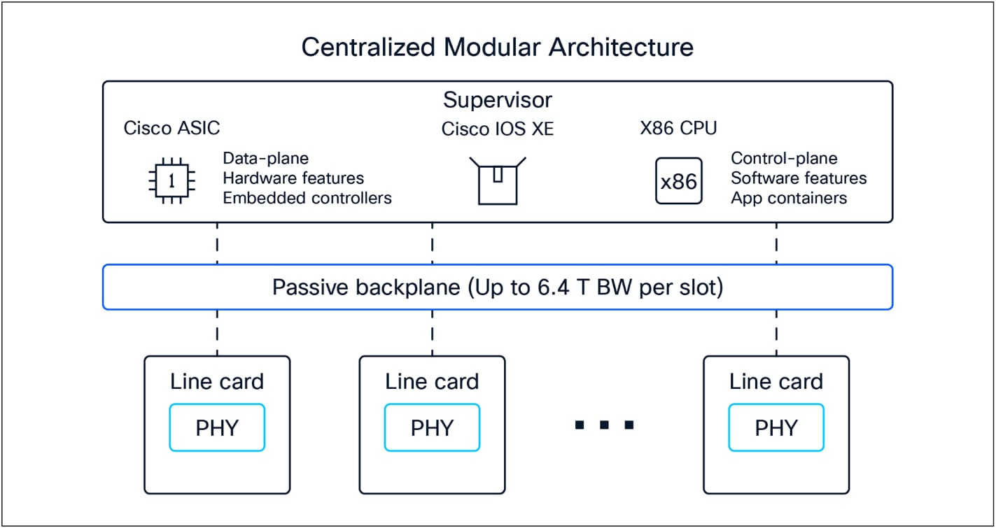
● Centralized modular architecture with a passive cable backplane.
● Support for up to 12.8 Tbps (6.4 Tbps full duplex) bandwidth per slot.
● Uses high-performance cables with up to 100 GE SerDes and 64 SerDes per slot.
◦ The Supervisor 3/XL’s backplane connects to four E100 or K100 ASICs, each handling 128x 50 GE SerDes lanes.
◦ This means the C9610 backplane is using only 50 GE speed for the Supervisor 3/XL. (Figure 11).
● The architecture supports uninterrupted supervisor switchover; forwarding, queuing, and security processing on the supervisor; and a modular design with front-to-back airflow.
● The passive backplane design contributes to higher MTBF and supports modular line cards compatible with the supervisor modules.

Cisco C9610 Series cable backplane
Cisco C9610 Series Smart Switches offer two supervisors: Supervisor Engine 3 (based on E100 ASICs) and Supervisor Engine 3 XL (based on K100 ASICs).
Both supervisor engines, referred to here as Supervisor 3/XL, come in a 2.5-Rack Unit (RU) design optimized for high-performance Printed Circuit Board (PCB) layout and airflow in a centralized architecture. A centralized architecture simplifies overall system design, minimizes port-to-port latency, and maximizes high availability, and MTBF.
Each Supervisor 3/XL is powered with four Cisco Silicon One E100 or K100 ASICs and one Cisco Silicon One Q200L ASIC (Figure 3). The Cisco Silicon One E100 and K100 ASICs are capable of 51.2 Tbps (25.6 Tbps full duplex) switching capacity and up to 15.6 Bpps of forwarding performance. There are no uplinks on the Supervisor 3/XL, as the ASIC connections are dedicated to the line cards. This means the Supervisor 3/XL can provide 32 ports of 100 GE for each line card slot.
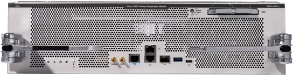
Cisco C9610 Series Supervisor Engine 3 XL
Cisco C9610 Series line card slots are designed for 1.25RU space for optimized airflow. They offer the ability to mix and match a range of line cards to support different core and aggregation deployments. Most of the existing Catalyst C9600 Series line cards can be reused on the Cisco C9610 chassis using a line card adapter (Figure 4).
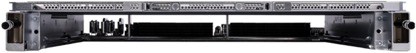
C9610-LC-ADPT line card adapter
Two new 1.25RU line cards have been introduced along with the Supervisor 3/XL (Figure 5).
● C9610-LC-32CD: 32-port 100/40 GE (QSFP28/QSFP+) or 24-port 100/40 GE (QSFP28/QSFP+) and 2-port 400/2001/100/40 GE (QSFP-DD/QSFP56/QSFP28/QSFP+) line card
● C9610-LC-40YL4CD: 40-port 50/25/10/11 GE (SFP56/SFP28/SFP+) and 4-port 100/40 GE (QSFP28/QSFP+) or 2-port 400/2001/100/40 GE (QSFP-DD/QSFP56/QSFP28/QSFP+) line card
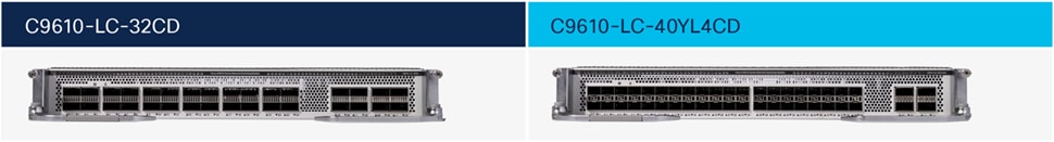
C9610 native line cards
Fiber line cards (with adapter)
● C9600X-LC-56YL4C: 56-port 50/25/10/11 GE (SFP56/SFP28/SFP+) and 4-port 100/40 GE (QSFP28/QSFP+) line card
● C9600X-LC-32CD: 30-port 100/40 GE (QSFP28/QSFP+) and 2-port 400/2001/100/40 GE (QSFP-DD/QSFP56/QSFP28/QSFP+) line card
● C9600-LC-40YL4CD: 40-port 50/25/10/11 GE (SFP56/SFP28/SFP+/SFP), 2-port 2001/100/40 GE (QSFP56/QSFP28/QSFP+), and 2-port 400/2001/100/40 GE (QSFP-DD/QSFP56/QSFP28/QSFP+) line card
Copper line card (with adapter)
● C9600-LC-48TX: 48-port 10/11 GE RJ-45 line card
This section briefly describes the highlights of the Cisco C9610 Series chassis.
Table 1 provides information about the capabilities of the chassis.
Table 1. Chassis specifications
| Cisco C9610R |
|
| Supervisor slots |
2 (slots 5 and 6) |
| Line card slots |
8 (slots 1, 2, 3,and 4 and slots 7, 8, 9, and 10) |
| Port density (without breakout or QSA) |
16x QSFP-DD (400 GE) 16x QSFP56 (200 GE1) 256x QSFP28 (100 GE), QSFP+ (40 GE) 448x SFP56 (50 GE), SFP28 (25 GE), SFP+ (10 GE), SFP (1 GE1) 384x RJ-45 (10 GE,1 GE1) |
| Dimensions (HxWxD) |
31.47 x 17.4 x 26.1 in. (79.93 x 44.20 x 66.29 cm) (18RU) |
| Bandwidth per line card slot |
12.8 Tbps (6.4 Tbps full duplex)1 |
| Power supplies |
8 (combined mode, N+1, and N+N) |
| Cooling |
Front to back |
The Cisco C9610 power supplies are Energy Star rated as Titanium or Platinum efficient (95%/90% or higher efficiency).
An ACT2 Trust Anchor module (TAm) chip for module authenticity is supported on all supervisors, line cards, and fan trays.
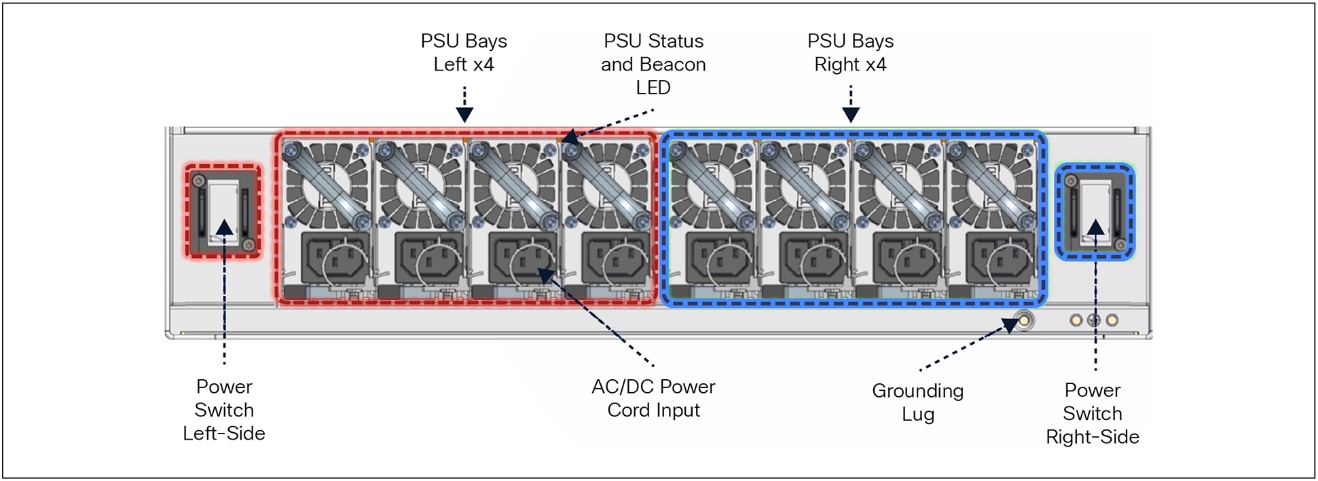
The Cisco C9610 Series uses a modular design for power. The C9610R chassis has eight slots for power supplies (Figure 6). Each power supply is very compact but highly efficient. The system provides support for both combined, N+1, and N+N redundant mode.
By default, the system operates in combined mode. In this mode, all power supplies are active and sharing the load. In N+1 redundant mode, one of the power supplies is configured as the standby power supply. In N+N redundant mode, an even number of power supplies is required, for example, six or eight.
Note: The recommendation is to use 3kW power supplies with 220V input to get the highest efficiency and redundancy.
The Cisco Power Calculator (https://cpc.cloudapps.cisco.com/cpc/launch.jsp) can help you determine the power supplies required for a given configuration. The tool also provides heat dissipation information.
Cisco C9610R chassis power
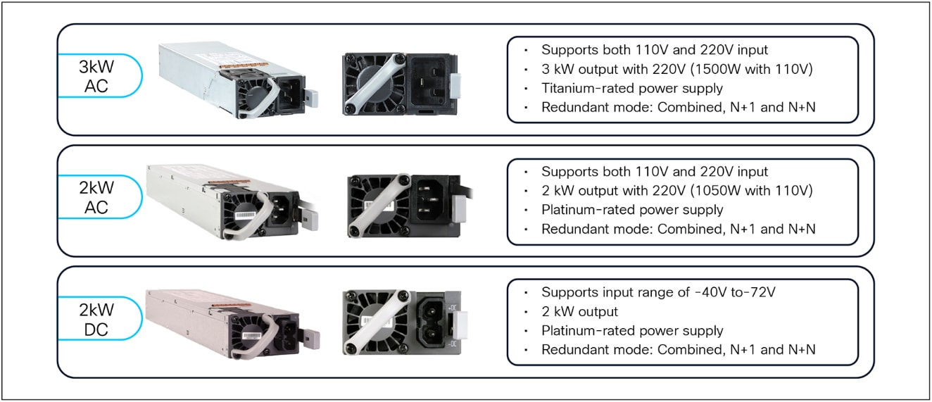
The maximum output power per Power Supply Unit (PSU) for the Cisco C9610 Series is listed below, and each PSU has a power holdup time of approximately 20 milliseconds at 100% load. Each PSU comes with front-to-back variable-speed cooling fans and has a push-release lock for simple and secure online insertion and removal (Figure 7).
● 3000W AC PS with 240V input (1500W with 120V input; 16A input)
● 2000W AC PS with 240V input (1050W with 120V input; 10.5A input)
● 2000W DC PS with 48V input (50A input)
To enable a diverse range of deployments, the Cisco C9610 Series also supports combinations of AC and DC units. When combining power supplies, both types of power supplies need to have the same power output level.
Power supply units
The Cisco C9610 Series Smart Switches come with four hot-swappable and field-replaceable fan trays that can be replaced from the back of the chassis (Figure 8). The chassis supports front-to-back airflow. The fan trays are responsible for cooling the entire chassis and for interfacing with environmental monitors to trigger alarms when conditions exceed thresholds. The fan trays contain thermal sensors to detect ambient temperature and adjust the fan speed. The chassis supports a hardware failure of up to one individual fan tray, and if a fan tray fails, the remaining fan trays will automatically increase their rpm to compensate and maintain sufficient cooling. If the switch fails to meet the minimum number of required fans, it shuts down automatically to prevent the system from overheating.
The Cisco C9610R chassis is equipped with onboard thermal sensors to monitor the ambient temperature at various points and report thermal events to the system so that it can adjust the fan speeds.
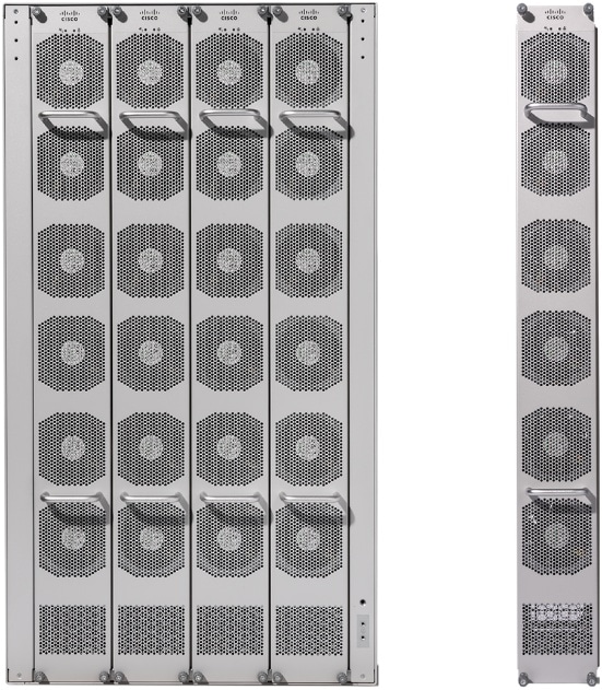
Back fan-tray servicing
The Cisco C9610 Series fan trays support front-to-back airflow for both modules and power supplies (Figure 9).
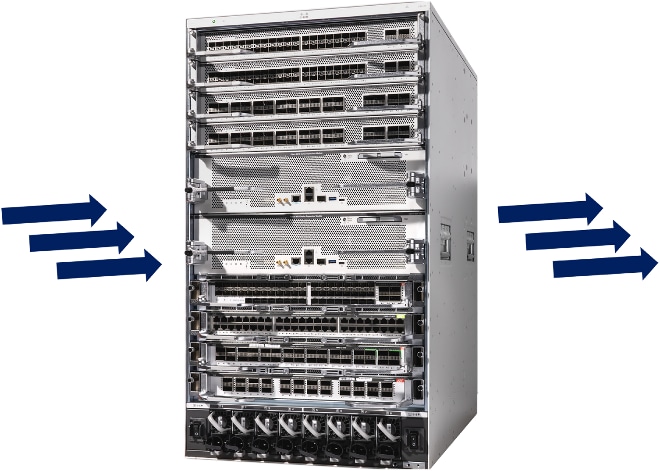
Chassis airflow
The Cisco C9610 Series switches are based on a centralized architecture (Figure 10). All forwarding, security, and queueing are done on the supervisor engine, while the line cards are considered transparent, containing only PHYs and control logic. Each line card slot has up to a 12.8 Tbps (6.4 Tbps full-duplex) connection to each of the supervisor slots.
The simplicity of a centralized design allows easy upgrade of features and additional bandwidth just by upgrading the supervisor, while keeping the existing line cards. The combination of the centralized architecture and transparent line cards also provides uninterrupted supervisor switchover, which is the foundation for the in-service software upgrade feature.
Cisco C9610 Series architecture
The Cisco C9610 Series Supervisor 3/XL is powered by one x86 CPU processor and five Cisco Silicon One ASICs (Figure 11). Both the Supervisor Engine 3 and the Supervisor Engine 3 XL provide 51.2 Tbps (25.6 Tbps full duplex). With the Cisco C9610R chassis, the Supervisor 3/XL provides each slot with 6.4 Tbps (3.2 Tbps full duplex) bandwidth.
Note: Due to high-performance line card requirements, the Supervisor 3/XL module does not have any dedicated uplink ports (any port on any line card can be used as an uplink).
The Supervisor 3/XL architecture consists of the following main components:
● Silicon One ASICs (4x E100 or K100 ASICs + 1x Q200L ASIC)
● Fabric ASIC interconnect
● X86 CPU and DRAM complex
● External connections (Mgmt, USB, Console, SSD, etc.)
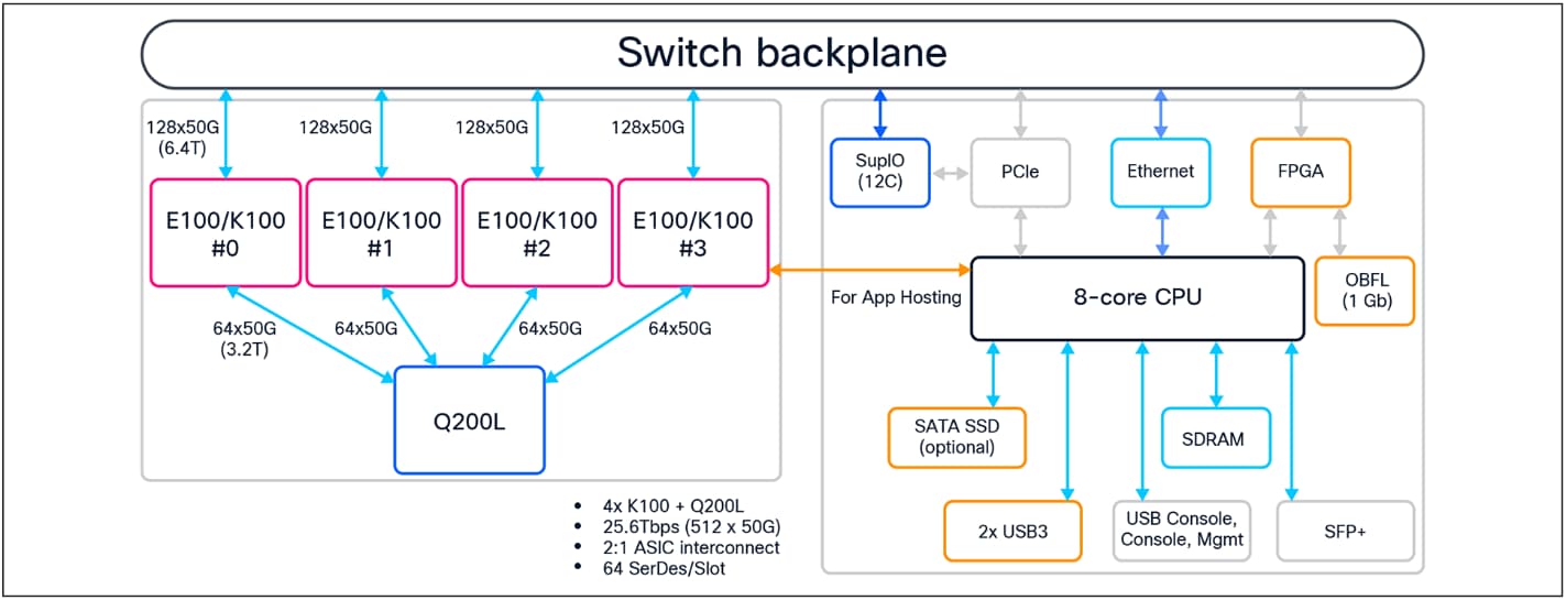
Supervisor Engine 3 block diagram
Cisco Silicon One E100/K100 ASIC
The Supervisor 3/XL is built with four Cisco Silicon One K100 or E100 forwarding ASICs and one Q200L fabric ASIC, which are based on an advanced programmable multislice System-On-Chip (SOC) architecture (Figure 12).
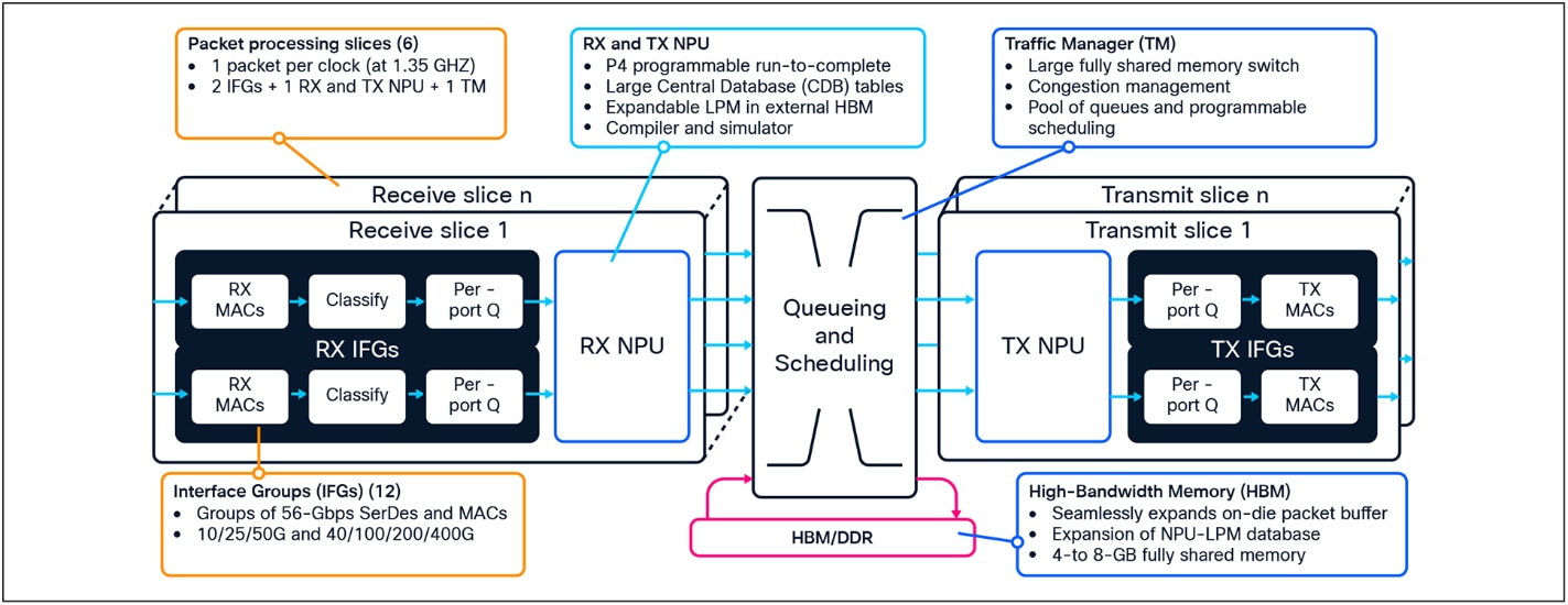
Cisco Silicon One ASIC diagram
Cisco Silicon One is a breakthrough multislice network processing technology that enables a single silicon architecture to span a massive portion of the networking market. Multislice architecture is a recent design innovation to combine multiple Network Processing Units (NPUs) onto a single die package to multiply total capacity. Each ASIC NPU pipeline (called a “slice”) operates independently and connects via an integrated crossbar “fabric.”
Cisco Silicon One multislice ASICs use an integrated Virtual Output Queue (VOQ) buffer architecture to manage traffic between slices. This design approach addresses many of the limits of NPU clock speeds while also multiplying overall ASIC throughput. The latest Cisco Silicon One generations are built with 7-nanometer and smaller technology, which offers significantly larger tables and bandwidth compared to previous ASICs.
The latest Cisco Silicon One E100 and K100 ASICs introduce next-generation (NPU 2.0) capabilities while expanding programmable packet processing pipelines and flexible allocation of hardware resources, for different places in the network.
The following are the key E100/K100 capabilities (per ASIC):
● Switching throughput (two slices): Up to 12.8 Tbps (6.4 Tbps full duplex)
● Forwarding performance (two slices): Up to 3.9 Bpps
● Forwarding Information Base (FIB) table: Up to 2 million IPv4 routes, up to 1 million IPv6 routes
● Algorithmic TCAM (HCAM) table: Up to 256,000 ingress and 256,000 egress entries (shared by Access Control Lists [ACL], Flexible NetFlow [FNF], Quality of Service [QoS], policy-based routing [PBR], etc.)
● Unified buffer: 64-MB built in low-latency shared memory, with optional (K100-only) 8-GB High-Bandwidth Memory (HBM)
Please visit the Cisco Silicon One product pages for more information.
ASIC interconnect
The C9610 Supervisor 3/XL is built with four Cisco Silicon One K100 or E100 forwarding ASICs and one Q200L fabric ASIC (Figure 13). Communication between slices of the same K100 or E100 is locally switched within the ASIC, meaning that packets destined to local ports within the same ASIC do not use the ASIC interconnect.
The purpose of the ASIC interconnect is to move data between multiple E100 or K100 ASICs. During inter-ASIC communication, sending full line-rate traffic (6.4 Tbps) from one ASIC to another via the Q200L interconnect can result in a 2:1 oversubscription scenario.
Note: Refer to the Mapping Ports to ASICs section (Figures 21 and 22).
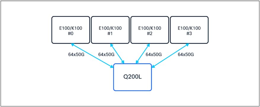
Supervisor 3/XL ASIC interconnect
The C9610 Supervisor 3/XL uses an x86 CPU architecture. The CPU complex has the following highlights:
● Gen10 Intel® 2.0-GHz x86 CPU with eight cores
● 32-GB DDR4 RAM
● 16-GB internal enhanced USB flash
● SATA SSD internal storage (up to 960 GB)
● Console supports USB-C and RJ-45 connectivity
● Supports one USB 3.0 port
● Management port supports RJ-45 (1 GE) and 1x SFP+ (10 GE)
● System reset switch for manually resetting the supervisor
The C9610 Supervisor 3/XL provides two types of external data storage:
● USB 3.0 on the front panel of the supervisor
● SATA SSD: Removable slot on the front-panel of the supervisor (up to 960 GB) (Figure 14)
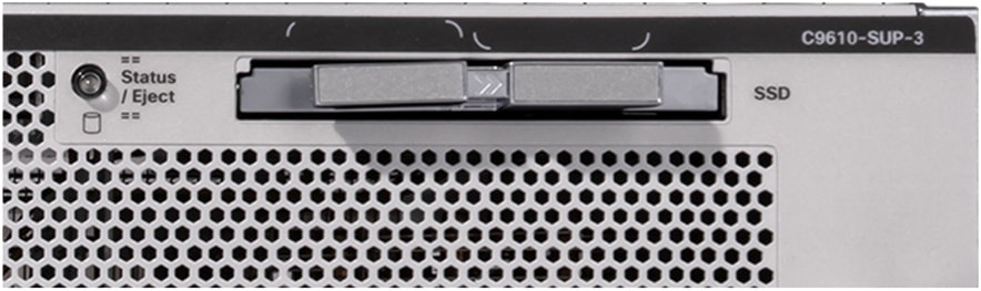
Supervisor 3/XL SATA SSD slot
This external storage can be used as general-purpose storage for packet capture, operation system trace logs, and graceful insertion and removal snapshots. Most importantly, the SATA SSD can be used for application hosting. An application hosted on a network device can serve a variety of purposes, ranging from automation, configuration management monitoring, and integration with existing tool chains.
Internal flash storage cannot be used to store third-party applications, as it is not supposed to be formatted as an EXT2 or EXT4 file system. But the SATA SSD can support an EXT2 or EXT4 (default) file system and application hosting. It also has the ability to monitor the health of the SSD storage through Self-Monitoring, Analysis, and Reporting Technology (SMART).
Supervisor and line card connections
Cisco C9610 Series line card slots have dedicated connections to both supervisor slots. Once the line cards are up and running, all traffic entering the line cards is sent to both the SSO active and hot standby supervisors. The hot standby supervisor processes those packets just like the active supervisor does, and the resulting packets are sent to the egress line cards. The egress line cards themselves select the packets from the active supervisor and send them out of the front panel ports (Figure 15).
If there is a switchover between the supervisors, the PHYs in the line cards just need to switch the connection to the new active supervisor. As a result, the outage during this event is very minimal (on average less than 10 ms). This capability, together with the centralized architecture, enables the Cisco C9610 Series to provide uninterrupted SSO and ISSU.
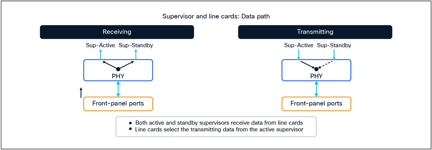
Supervisors and line card connections
The Ethernet PHY (physical layer) connects a link layer device (often a MAC) to a physical medium such as a transceiver. The PHY on the Cisco C9610 Series line cards is a fully integrated Ethernet transceiver supporting traffic steering and mapping of SerDes lanes back to the ASIC to enable multiple speeds depending on the front panel ports.
C9610-LC-32CD and C9600X-LC-32CD
● Up to 30 ports of 100/40 GE non-blocking (Figure 17)
● 28 ports of 100/40 GE and 2 ports of 400/2001/100/40 GE non-blocking (Figure 17)
● QSA adapter supported for 10/11 GE speed
● Speed is auto-negotiated depending on the inserted optics
Figure 16 shows the architecture of the C9610-LC-32CD and C9600X-LC-32CD line cards.
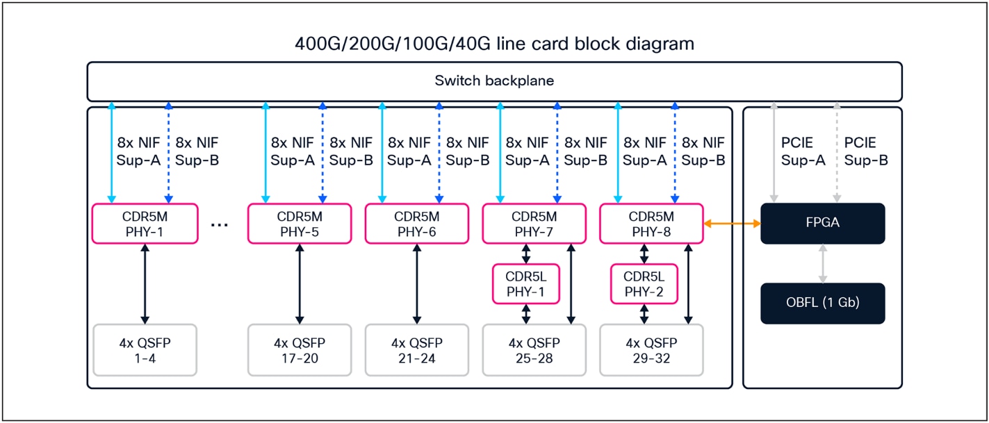
Diagram for the C9610-LC-32CD and C9600X-LC-32CD line cards
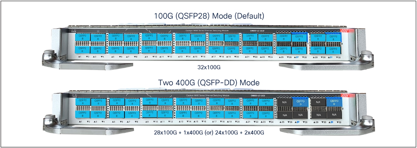
Available ports configuration mode with C9610-LC-32CD and C9600X-LC-32CD line cards
C9610-LC-40YL4CD and C9600-LC-40YL4CD
● Up to 40 ports of 50/25/10/11 GE and 4 ports of 2001/100/40 GE non-blocking
● Up to 40 ports of 50/25/10/11 GE and 2 ports of 400/2001/40 GE non-blocking
● QSA adapter supported on QSFP ports for 10 GE speed
● Speed is auto-negotiated depending on the inserted optics
Figure 18 shows the architecture of the C9610-LC-40YL4CD and C9600-LC-40YL4CD line cards.
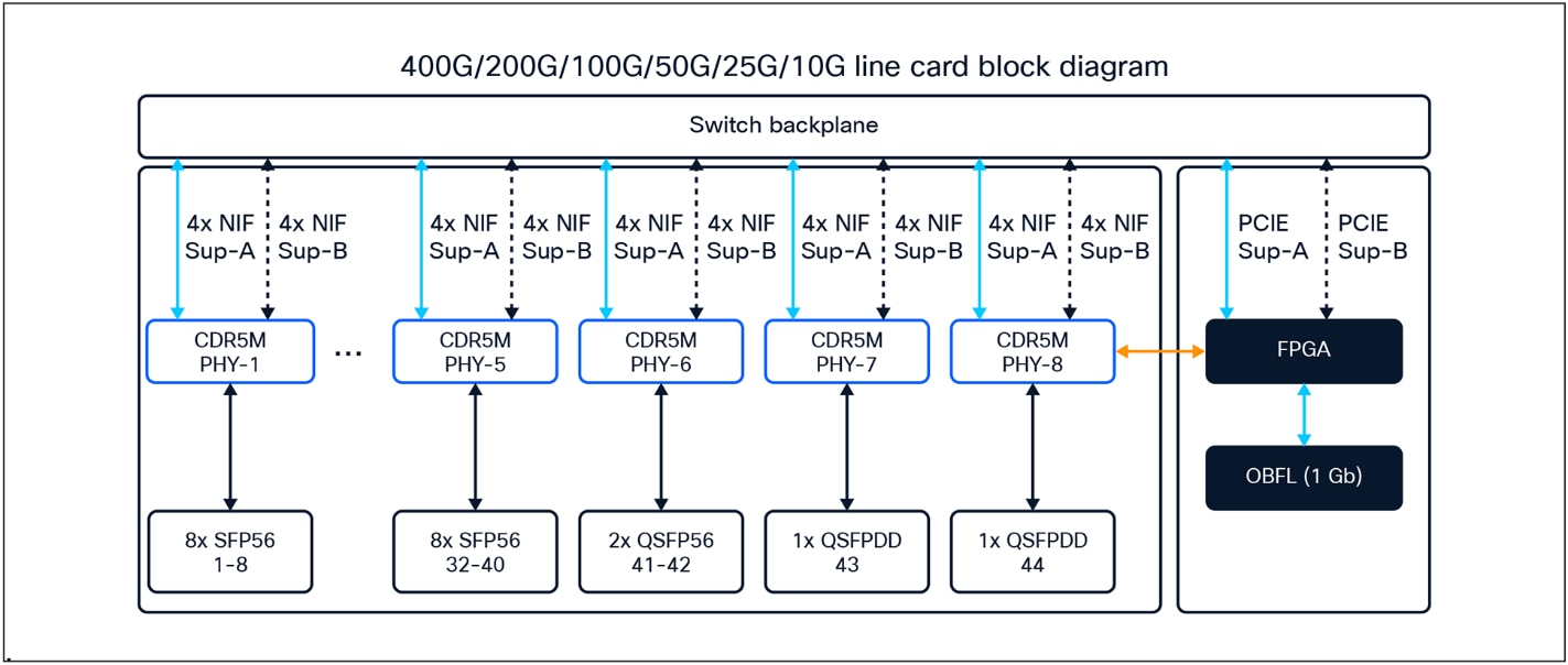
Diagram for the C9610-LC-40YL4CD and C9600-LC-40YL4CD line cards
● Up to 56 ports of 50/25/10/11 GE and 4 ports of 100/40 GE non-blocking
● Speed is auto-negotiated depending on the inserted optics
Figure 19 shows the architecture of the C9600X-LC-56YL4C line card.
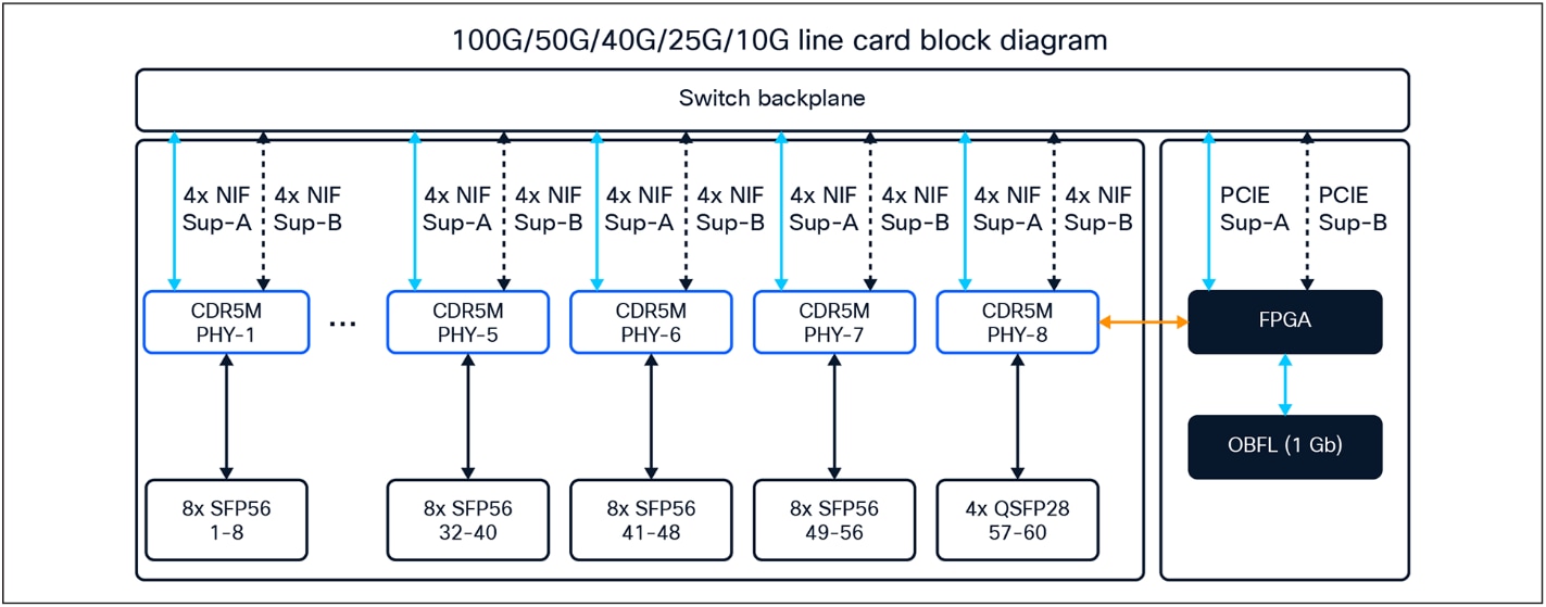
Diagram for the C9600X-LC-56YL4C line card
● Up to 48 ports of 10/11 GE nonblocking
● No Power over Ethernet (PoE) on these ports
Figure 20 shows the architecture of the C9600-LC-48TX line card.
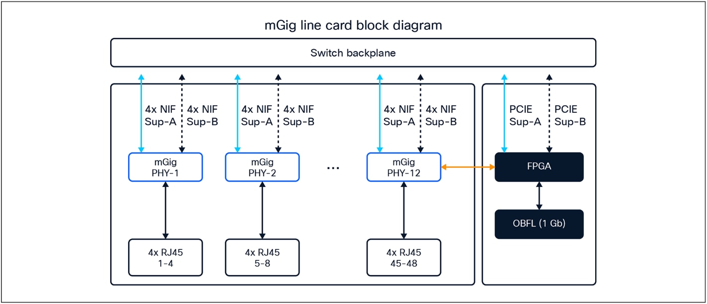
Diagram for C9600-LC-48TX line card
The Supervisor 3/XL uses four Cisco Silicon One E100 or K100 ASICs to provide connectivity for all C9610R chassis slots and ports. Each line card distributes its front-panel ports evenly across all four ASICs. Each front-panel port will be mapped to a specific ASIC (numbered 0-3) and a specific ASIC slice/core (numbered 0-1).
Note: Since each line card model supports different ports and speeds, the mapping of front-panel ports to ASICs depends on each line card.
For example, for a C9610-LC-32CD installed in slot 3, ports HundredGigE 3/0/1 through 3/0/4 are mapped to ASIC 3, Slice/Core 1, while ports HundredGigE 3/0/5 through 3/0/8 are mapped to ASIC 1, Slice/Core 1 (see Figures 21 and 22).
Inter-ASIC communication, which uses the ASIC interconnect via the Q200L fabric, introduces higher latency relative to intra-ASIC communication. This is due to increased signal propagation distances (across multiple ASICs), protocol overhead, and the requirement for additional buffering and arbitration between ASICs. In contrast, intra-ASIC communication benefits from lower latency, as data paths remain within a single ASIC.
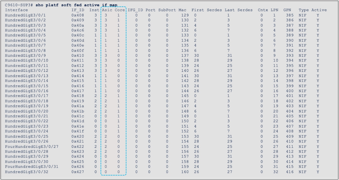
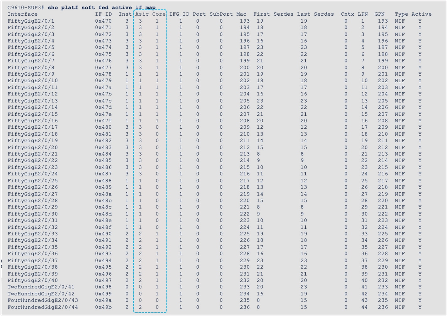
Interface-to-ASIC mapping of C9610-LC-32CD and C9610-LC-40YL4CD
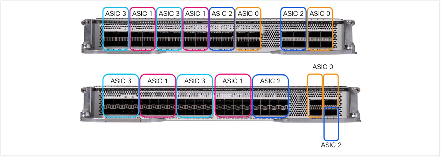
Interface-to-ASIC mapping view of C9610-LC-32CD and C9610-LC-40YL4CD
Supervisor 3 and Supervisor 3 XL comparison
The Cisco C9610 Smart Switches are continuing Cisco’s leadership in modular campus core and distribution switches by providing a full suite of campus core features, along with higher performance and scale. With the Supervisor 3, the C9610 Series platform already provides a best-in-class core feature set with hardware performance and scale for Catalyst 6500 and 6800 Series non-XL deployments. The Supervisor 3 XL introduces superior hardware feature scale (up to 2 million IPv4 routes with 8 GB of HBM) for migration of Catalyst 6500 and 6800 Series XL deployments.
The Switch Database Management (SDM) template is a feature on Cisco C9610 switches that determines how the switch allocates its hardware resources. Cisco Silicon One ASICs support three major tables, including Longest Prefix Match (LPM) for IP/mask routes; Central Exact Match (CEM) for IP hosts, multicast routes, Network Address Translation (NAT) and other exact match entries; and a new algorithmic hash-based TCAM (HCAM) for ACLs, QoS, FNF, and other ACL entries.
Table 2 covers the default SDM template available on the Supervisor Engines 3 and 3 XL.
Note: A customizable SDM will be available in a future IOS XE software release. With a custom SDM, you can optimize the switch for specific deployment scenarios (e.g., routing focused, switching focused, security focused, etc.).
Table 2. Supervisor Engines 3 and 3 XL default SDM scale
|
|
Supervisor 3 |
Supervisor 3 XL |
|
|
Default |
Default |
| MAC addresses |
128,000 |
128,000 |
| IP host routes |
128,000 |
128,000 |
| Multicast Layer 2 groups |
16,000 |
16,000 |
| Multicast Layer 3 routes |
32,000 |
32,000 |
| IP LPM routes |
1 million |
2 million |
| MPLS labels |
64,000 |
128,000 |
| Security group tag/OG labels |
24,000 |
24,000 |
| Security ACL entries |
21,000 |
36,000 |
| QoS ACL entries |
5,000 |
8,000 |
| PBR ACL entries |
8,000 |
16,000 |
| Flexible NetFlow |
32,000 |
64,000 |
This section provides a high-level overview of how packet forwarding is performed on the Cisco C9610 Series Smart Switches.
Supervisor 3/XL – Unicast forwarding in Silicon One E100/K100 ASIC
Figure 23 shows the basic sequence of events when packets enter the Cisco C9610 Series front panel ports for unicast packet forwarding, within a single Silicon One E100 or K100 ASIC.
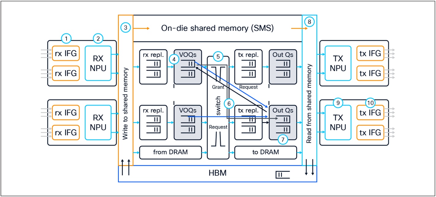
Unicast packet walk in Silicon One E100 or K100 ASIC
1. Packet arrives at the line card’s ingress port; PHY converts the signal, serializes the bits, and then sends the packet to the Receive Interface Group (Rx IFG) through the backplane.
2. The packet’s Start-of-Packet (SOP) fragment (64B to 384B elements) is processed by the Receive Network Processor Unit (Rx NPU) to determine the destination port. Non-SOP fragments bypass the Rx NPU.
3. The packet is stored in the Shared Memory Packet Buffer (SMS), and a corresponding Packet Descriptor (PD) is generated.
4. The PD is stored in the Virtual Output Queue (VOQ) according to the destination port.
5. The VOQ scheduler requests credits from the destination Output Queue (OQ).
6. Once credit is granted from the OQ, the VOQ passes the PD to the local slice crossbar.
7. The PD is then switched by the crossbar and is stored in the destination OQ.
8. The PD is scheduled from the OQ and presented to the SMS. The packet is then read out to the Transmit Network Processor Unit (Tx NPU).
9. The packet is processed by the Tx NPU by editing the packet’s SOP elements.
10. The packet is then transmitted out of an interface within a Tx IFG.
Figure 24 shows the basic sequence of events for inter-ASIC processing, using the Q200L fabric ASIC interconnect.
1. Packet arrives at the line card’s ingress port; PHY converts the signal, serializes the bits, and then sends the packet to the Receive Interface Group (Rx IFG) through the backplane.
2. The packet’s Start-of-Packet (SOP) fragment (64B to 384B elements) is processed by the Receive Network Processor Unit (Rx NPU) to determine the destination port. Non-SOP fragments bypass the Rx NPU.
3. The packet is stored in the Shared Memory Packet Buffer (SMS), and a corresponding Packet Descriptor (PD) is generated.
4. The PD is stored in the Virtual Output Queue (VOQ) according to the destination port.
5. The VOQ scheduler requests credits from the destination Output Queue (OQ), via the fabric slice of ingress K100 or E100 ASIC, Q200L ASIC, and fabric slice of egress K100 or E100 ASIC.
6. Once credit is granted from the OQ, the VOQ passes the PD to the fabric slice crossbar. The PD is then switched by the fabric slice crossbar (via the Q200L) and is stored in the destination OQ.
7. The PD is scheduled from the OQ and presented to the SMS. The packet is then read out to the Transmit Network Processor Unit (Tx NPU).
8. The packet is processed by the Tx NPU by editing the packet’s SOP elements.
9. The packet is then transmitted out of an interface within a Tx IFG.
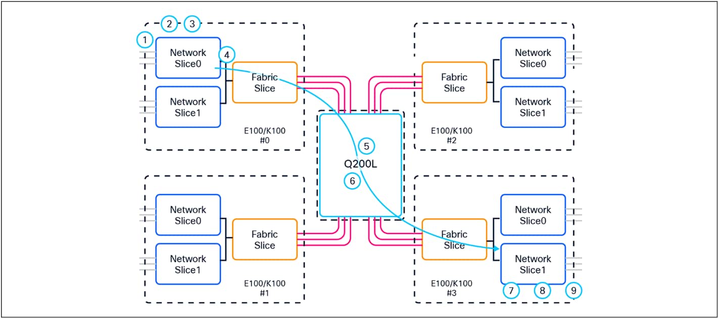
Inter-ASIC packet walk view
Supervisor 3/XL – Multicast forwarding in Silicon One E100/K100 ASIC
Figure 25 shows the basic sequence of events when packets enter the Cisco C9610 Series front panel ports for multicast packet forwarding within the single Silicon One E100 or K100 ASIC.
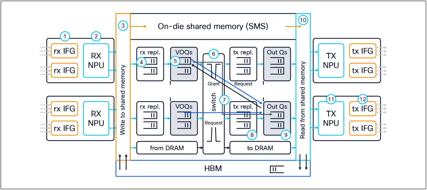
Multicast packet walk
1. Packet arrives at the line card’s ingress port; PHY converts the signal and serializes the bits and then sends the packet to the Receive Interface Group (Rx IFG) through the backplane.
2. The packet’s Start-of-Packet (SOP) fragment (64B to 384B elements) is processed by the Rx NPU to determine the destination port. Non-SOP fragments bypass the Receive Network Processor Unit (Rx NPU) and are passed directly to the Shared Memory Packet Buffer (SMS).
3. The packet is stored in the SMS, and a corresponding Packet Descriptor (PD) is generated.
4. Receive replication (RXPDR) is processed for ingress replication. Each copy made by RXPDR results in an enqueue into the Virtual Output Queue (VOQ).
5. The replicated PDs are stored in the VOQ according to the destination ports.
6. The VOQ requests credits from the destination Output Queue (OQ).
7. Once credit is granted from the OQ, the VOQ passes the PD to the slice crossbar.
8. The PD is then switched by the crossbar and sent to Transmit Replication (TXPDR) for egress multicast replication.
9. Once the packet is replicated, it is stored in the destination OQs.
10. The PD is scheduled from the OQ and presented to the SMS. The packet is then read out to the Transmit Network Processor Unit (Tx NPU).
11. The packet is processed by the Tx NPU by editing the packet’s SOP elements.
12. The packet is then transmitted out of an interface within an Tx IFG.
The Cisco C9610 Series Smart Switches represent a major evolution in modular campus core switching, purpose-built to meet the increasing demands of AI-powered applications, secure hybrid work, and scalable enterprise networking. With the benefits of centralized architecture and built on the foundation of next-generation Cisco Silicon One ASICs, the C9610 switches deliver industry-leading performance, reliability, and security.
Offering up to 51.2 Tbps of throughput, 400G readiness, and high-availability features such as redundant supervisors and in-service software upgrades, the C9610 platform helps ensure resilient operations and future-ready scalability. Seamless integration with both Catalyst and Meraki management ecosystems provides flexibility in deployment and operations, while unified licensing and support simplify lifecycle management.
As enterprise networks continue to transform, the Cisco C9610 Series provides the architectural backbone for organizations seeking to modernize their core infrastructure—enabling them to securely and efficiently support the digital and AI workloads of tomorrow.
The following websites offer more details on the Cisco C9610 Series and its capabilities.
Cisco C9610 Series Switches Data Sheet
Cisco Silicon One Product Family White Paper