-
Cisco MDS 9000 Family Fabric Manager Configuration Guide, Release 1.3 (from Release 1.3(1) through Release 1.3(6))
-
Index
-
New and Changed Information
-
Preface
-
Product Overview
-
Getting Started with Cisco Fabric Manager
-
Overview of Fabric Manager Components
-
Before You Begin
-
Obtaining and Installing Licenses
-
Initial Configuration
-
Configuring High Availability
-
Software Images
-
Managing Modules
-
Managing System Hardware
-
Configuring and Managing VSANs
-
Configuring Interfaces
-
Configuring Trunking
-
Configuring PortChannels
-
Configuring and Managing Zones
-
Configuring Inter-VSAN Routing
-
Managing FLOGI, Name Server, FDMI, and RSCN Databases
-
Configuring Switch Security
-
Configuring Fabric Security
-
Configuring Port Security
-
Configuring Fibre Channel Routing Services and Protocols
-
Configuring IP Services
-
Configuring FICON
-
Configuring IP Storage
-
Configuring Call Home
-
Configuring Domain Parameters
-
Configuring Traffic Management
-
Configuring System Message Logging
-
Discovering SCSI Targets
-
Monitoring Network Traffic Using SPAN
-
Advanced Features and Concepts
-
Configuring Fabric Configuration Servers
-
Monitoring System Processes and Logs
-
Troubleshooting the Fabric
-
Troubleshooting Fabric Manager Issues
-
 Feedback
Table Of Contents
Configuring Fibre Channel Interfaces
Configuring TL Port ALPA Caches
Configuring Buffer-to-Buffer Credits
Configuring Performance Buffers
Configuring Switch Port Defaults
Configuring Gigabit Ethernet Interfaces
Managing Interface Attributes for Ports
Configuring Interfaces
A switch's relay frames from one data link to another. To do that, the characteristics of the interfaces through which the frames are received and sent must be defined. The configured interfaces can be Fibre Channel interfaces, management interface (mgmt0), or VSAN interfaces.
This chapter describes the basic interface configuration to get your switch up and running.
Before you begin configuring the switch, ensure that the modules in the chassis are functioning as designed.
This chapter contains the following topics:
•
Configuring Fibre Channel Interfaces
•
•
Configuring Fibre Channel Interfaces
This section describes Fibre Channel interface characteristics, including (but are not limited to) modes, states, and speeds.
This section contains the following topics:
•
•
•
•
About Interface Modes
Each physical Fibre Channel interface in a switch may operate in one of several modes: E port, F port, FL port, TL port, TE port, and SD port. Besides these modes, each interface may be configured in auto or Fx port mode. These two modes determine the port type during interface initialization. Figure 12-1 shows different interface modes.
Figure 12-1 Cisco MDS 9000 Family Switch Interface Modes
Interfaces are created in VSAN 1 by default.
Each interface has an associated administrative configuration and an operational status:
•
•
E Port
In expansion port (E port) mode, an interface functions as a fabric expansion port. This port may be connected to another E port to create an Inter-Switch Link (ISL) between two switches. E ports carry frames between switches for configuration and fabric management. They serve as a conduit between switches for frames destined to remote N ports and NL ports. E ports support class 2, class 3, and class F service.
An E port connected to another switch may also be configured to form a PortChannel
F Port
In fabric port (F port) mode, an interface functions as a fabric port. This port may be connected to a peripheral device (host or disk) operating as an N port. An F port can be attached to only one N port. F ports support class 2 and class 3 service.
FL Port
In fabric loop port (FL port) mode, an interface functions as a fabric loop port. This port may be connected to one or more NL ports (including FL ports in other switches) to form a public arbitrated loop. If more than one FL port is detected on the arbitrated loop during initialization, only one FL port becomes operational and the other FL ports enter nonparticipating mode. FL ports support class 2 and class 3 service.
TL Port
In translative loop port (TL port) mode, an interface functions as a translative loop port. It may be connected to one or more private loop devices (NL ports). TL port mode is specific to Cisco MDS 9000 family switches and have similar properties as FL ports. TL ports enable communication between a private loop device and one of the following devices:
•
•
•
•
TL ports support class 2 and class 3 services. Private loop devices refer to legacy devices that reside on arbitrated loops. These devices are not aware of a switch fabric because they only communicate with devices on the same physical loop.
Note
TE Port
In trunking E port (TE port) mode, an interface functions as a trunking expansion port. It may be connected to another TE port to create an Extended ISL (EISL) between two switches. TE ports are specific to Cisco MDS 9000 family switches. They expand the functionality of E ports to support the following:
•
•
•
In TE-port mode, all frames are transmitted in EISL frame format, which contains VSAN information. Interconnected switches use the VSAN ID to multiplex traffic from one or more VSANs across the same physical link. This feature is referred to as trunking in the Cisco MDS 9000 Family. TE ports support class 2, class 3, and class F service.
SD Port
In SPAN destination port (SD port) mode, an interface functions as a switched port analyzer (SPAN). The SPAN feature is specific to switches in the Cisco MDS 9000 Family. It monitors network traffic that passes though a Fibre Channel interface. This monitoring is done using a standard Fibre Channel analyzer (or a similar switch probe) that is attached to an SD port. SD ports do not receive frames, they merely transmit a copy of the source traffic. The SPAN feature is nonintrusive and does not affect switching of network traffic for any SPAN source ports.
ST Port
In the SPAN Tunnel port (ST port) mode, an interface functions as an entry point port in the source switch for the RSPAN Fibre Channel tunnel. The ST port mode and the remote SPAN (RSPAN) feature are specific to switches in the Cisco MDS 9000 Family. When configured in ST port mode, the interface cannot be attached to any device, and thus, cannot be used for normal Fibre Channel traffic.
Fx Port
Interfaces configured as Fx ports are allowed to operate in either F port or FL port mode. The Fx port mode is determined during interface initialization depending on the attached N port or NL port. This administrative configuration disallows interfaces to operate in any other mode--for example, preventing an interface to connect to another switch.
B Port
While E ports typically interconnect Fibre Channel switches, some SAN extender devices, such as Cisco's PA-FC-1G Fibre Channel port adapter, implement a bridge port (B port) model to connect geographically dispersed fabrics. This model uses B ports as described in the T11 Standard FC-BB-2.
When an FCIP peer is a SAN extender device that only support Fibre Channel B ports, you need to enable the B port mode for the FCIP link. When a B port is enabled, the E port functionality is also enabled and they coexist. If the B port is disabled, the E port functionality remains enabled.
Auto Mode
Interfaces configured as auto are allowed to operate in one of the following modes: F port, FL port, E port, or TE port. The port mode is determined during interface initialization. For example, if the interface is connected to a node (host or disk), it operates in F port or FL port mode depending on the N port or NL port mode. If the interface is attached to a third-party switch, it operates in E port mode. If the interface is attached to another switch in the Cisco MDS 9000 Family, it may become operational in TE port mode. TL ports and SD ports are not determined during initialization and are administratively configured.
About Interface States
The interface state depends on the administrative configuration of the interface and the dynamic state of the physical link.
Administrative States
The administrative state refers to the administrative configuration of the interface as described in the Table 12-1.
Operational States
The operational state indicates the current operational state of the interface. Table 12-2 describes the operational states.
Reason Codes
Reason codes are dependent on the operational state of the interface. Table 12-3 describes the reason codes for interface states.
If the administrative state is up and the operational state is down, the reason code differs based on the nonoperational reason code. Table 12-4 describes the reason codes for nonoperational states.
Configuring 32-port Switching Modules and Host-Optimized Ports
The 32-port 1/2-Gbps switching module contains 8 port groups of 4 ports each. When configuring these modules or the host-optimized ports in the Cisco 9100 Series, the following guidelines apply:
•
•
•
•
•
Configuring TL Port ALPA Caches
While TL ports cannot be automatically configured, you can manually configure entries in arbitrated loop physical address (ALPA) caches. Generally, ALPA cache entries are automatically populated when an ALPA is assigned to a device. Each device is identified by its port world wide name (pWWN). When a device is allocated an ALPA, an entry for that device is automatically created in the ALPA cache.
A cache contains entries for recently allocated ALPA values. These caches are maintained on various TL ports. If a device has an ALPA, the SAN-OS software attempts to allocate the same ALPA to the device each time. The ALPA cache is maintained in persistent storage and saves information across switch reboots. The maximum cache size is 1000 entries. If the cache is full, and a new ALPA is allocated, the SAN-OS software discards an inactive cache entry (if available) to make space for the new entry.
Configuring Buffer-to-Buffer Credits
Buffer-to-buffer credits (BB_credits) are a flow control mechanism to ensure that FC switches do not run out of buffers, since switches must not drop frames. Buffer Credits are negotiated on a per-hop basis.
The receive BB_credit (rxbbcredit) value may be configured for each FC interface. In most cases, you don't need to modify the default configuration.
The receive BB_credit values depend on the module type and the port mode:
•
•
Note
Configuring Performance Buffers
Regardless of the configured Rx BB_credit value, additional buffers, called performance buffers, improve switch port performance. Instead of relying on the built-in switch algorithm, you can manually configure the performance buffer value for specific applications (for example, forwarding frames over FCIP interfaces).
For each physical Fibre Channel interface in any switch in the Cisco MDS 9000 Family, you can specify the amount of performance buffers allocated in addition to the configured receive BB_credit value.
The default performance buffer value is 0. If you use the Default option, the built-in algorithm is used.
If you do not specify this command, the Default option is automatically used.
Configuring the Beacon Mode
By default, the beacon mode is disabled on all switches. The beacon mode is indicated by a flashing green light that helps you identify the physical location of the specified interface.
Identifying the Beacon LEDs
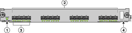
Figure 12-2 displays the status, link, and speed LEDs in a 16-port switching module.
Figure 12-2 Cisco MDS 9000 Family Switch Interface Modes
Status LED
Link LEDs and speed LEDs
1/2-Gbps Fibre Channel port group
Asset tag (refer to the Cisco MDS 9000 Family Hardware Installation Guide).
Each port has one link LED on the left and one speed LED on the right.
The speed LED displays the speed of the port interface:
•
•
•
The speed LED also displays if the beacon mode is enabled or disabled:
•
•
Configuring Switch Port Defaults
You can configure default values for various switch port attributes. If you configure the following attributes, they will be applied globally to all future switch port configurations, even if you do not individually specify them at that time.
Default Settings
Table 12-5 lists the default settings for Fibre Channel interface parameters.
Configuring VSAN Interfaces
VSANs apply to Fibre Channel fabrics and enable you to configure multiple isolated SAN topologies within the same physical infrastructure. You can create an IP interface on top of a VSAN and then use this interface to send frames to this VSAN. To use this feature, you must configure the IP address for this VSAN. VSAN interfaces cannot be created for nonexisting VSANs.
Follow these guidelines when creating or deleting VSAN interfaces:
•
•
•
You can configure each interface only in one VSAN.
After configuring the VSAN interface, you can configure an IP address or Virtual Router Redundancy Protocol (VRRP) features.
Configuring Gigabit Ethernet Interfaces
Each port or interface on the IPS module is displayed in the Ethernet Port dialog. To configure Ethernet port interfaces, perform the following steps:
Step 1
Step 2
Step 3
Step 4
Step 5
Step 6
Step 7
Enabling or Disabling Ports
To enable a port, right-click on a disabled port in Device Manager and choose Enable from the pop-up menu. To disable a port, right-click on a enabled port in Device Manager and choose Disable from the pop-up menu.
To enable or disable multiple ports, press the Ctrl key and click each port or drag the mouse around a group of ports. Then right-click any of the chosen ports and choose either Enable or Disable from the pop-up menu.
Managing Interface Attributes for Ports
To manage port interface attributes from the Fabric Manager, choose Physical Interfaces from the menu tree and then choose one of the following port types to be configured:
•
•
•
•
To manage port interface attributes from the Device Manager, select a port on a module, and then choose a port type from the Interface menu.
The Fabric Manager Information pane displays interface attributes for multiple switches. The dialog box from Device Manager displays interface attributes for a single switch.