-
Cisco MDS 9000 Family Fabric Manager Configuration Guide, Release 1.3 (from Release 1.3(1) through Release 1.3(6))
-
Index
-
New and Changed Information
-
Preface
-
Product Overview
-
Getting Started with Cisco Fabric Manager
-
Overview of Fabric Manager Components
-
Before You Begin
-
Obtaining and Installing Licenses
-
Initial Configuration
-
Configuring High Availability
-
Software Images
-
Managing Modules
-
Managing System Hardware
-
Configuring and Managing VSANs
-
Configuring Interfaces
-
Configuring Trunking
-
Configuring PortChannels
-
Configuring and Managing Zones
-
Configuring Inter-VSAN Routing
-
Managing FLOGI, Name Server, FDMI, and RSCN Databases
-
Configuring Switch Security
-
Configuring Fabric Security
-
Configuring Port Security
-
Configuring Fibre Channel Routing Services and Protocols
-
Configuring IP Services
-
Configuring FICON
-
Configuring IP Storage
-
Configuring Call Home
-
Configuring Domain Parameters
-
Configuring Traffic Management
-
Configuring System Message Logging
-
Discovering SCSI Targets
-
Monitoring Network Traffic Using SPAN
-
Advanced Features and Concepts
-
Configuring Fabric Configuration Servers
-
Monitoring System Processes and Logs
-
Troubleshooting the Fabric
-
Troubleshooting Fabric Manager Issues
-
 Feedback
Table Of Contents
Configuring the Ethernet Management Port
Configuring the Default Gateway
Configuring the Default Network
IP-ACL Configuration Guidelines
Adding Entries to an Existing IP-ACL
Managing IPFC Connectivity with Multiple VSANs
Creating or Removing a Virtual Router
Adding an IP Address for a Virtual Router
Viewing IP Address Information
Managing IP Addresses for VRRP
Setting Priority for the Virtual Router
Setting the Time Interval for the Advertisement Packet
Preempting the Master Virtual Router
Configuring Authentication for the Virtual Router
Setting the Priority Based on Interface State
Configuring VRRP Operations Attributes
Enabling or Disabling IP Forwarding
Viewing Information and Statistics
Viewing TCP Information and Statistics
Viewing UDP Information and Statistics
Configuring IP Services
Cisco MDS 9000 Family switches can route IP traffic between Ethernet and Fibre Channel interfaces. The IP static routing feature is used to route traffic between VSANs. To do so, each VSAN must be in a different IP subnetwork. Each Cisco MDS 9000 Family switch provides the following services for network management systems (NMS):
•
IP forwarding on the out-of-band Ethernet interface (mgmt0) on the front panel of the supervisor modules.
•
•
Switches are compliant with RFC 2338 standards for Virtual Router Redundancy Protocol (VRRP) features. VRRP is a restartable application that provides a redundant, alternate path to the gateway switch.
This chapter contains the following topics:
•
•
•
•
•
•
Traffic Management Services
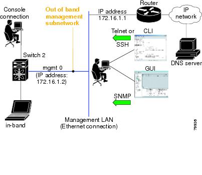
In-band options are compliant with and use the RFC 2625 standards. An NMS host running IP protocol over a FC interface can access the switch using the IPFC functionality. If the NMS does not have a Fibre Channel HBA, in-band management can still be performed using one of the switches as an access point to the fabric.
Figure 22-1 Management Access to Switches
Configuring the Ethernet Management Port
The management port on the switch allows multiple simultaneous Telnet or SNMP network management sessions. You can also configure the supervisor module Ethernet interface and VSAN interfaces as management ports. This section focuses on the Ethernet management port (mgmt0). You can remotely configure the switch through the management port. To configure a connection remotely, you must configure the IP parameters (IP address and subnet mask) from the CLI so that the switch is reachable.
Before you begin to configure the management interface manually, obtain the switch IP address and IP subnet mask. Also make sure the console cable is connected to the console port.
Configuring the Default Gateway
The IP address for a switch's default gateway should be configured along with the IP static routing commands (IP default-network, destination prefix, and destination mask, and next hop address)
Tip
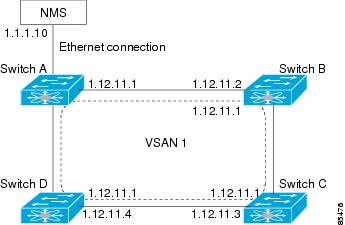
When the Ethernet interface is configured, the switch should point to the gateway router for the IP network. The host accesses the gateway using a gateway switch. This gateway switch is configured as the default gateway. The other switches in the fabric that are connected to the same VSAN as the gateway switch can also be connected through the gateway switch. Every interface connected to this VSAN should be configured with the VSAN IP address of the gateway switch.
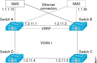
Figure 22-2 Overlay VSAN Functionality
In Figure 22-2, Switch A has the IP address 1.12.11.1, Switch B has the IP address 1.12.11.2, Switch C has the IP address 1.12.11.3, and Switch D has the IP address 1.12.11.4. Switch A is the gateway switch with the Ethernet connection. The NMS uses the IP address 1.1.1.10 to connect to the gateway switch. Frames forwarded to any switch in the overlaid VSAN 1 are routed through the gateway switch. Configuring the gateway switch's IP address, 1.12.11.1, in the other switches enable the gateway switch to forward the frame to the intended destination. Similarly, if a non-gateway switch in the VSAN forwards a frame to the Ethernet world, the frame is routed through the gateway switch.
When forwarding is disabled (default), IP frames are not sent from one interface to another. In these cases, the software performs local IP routing between two switches using the in-band option for Fibre Channel traffic and the mgmt0 option for Ethernet traffic.
When a VSAN is created, a VSAN interface is not created automatically. You need to specifically create the interface.
Configuring the Default Network
When IP routing is enabled on the switch, assign the IP default network address. The switch considers routes to that network as the last resort. If the IP default network address is not available, the switch uses the IP default gateway address. For every network configured with the IP default network address, the switch flags that route as a candidate default route, if the route is available.
Tip
Configuring an IP Route
To configure an IP route or identify the default gateway, perform the following steps.
Step 1
You see the IP Routes window.
Step 2
You see the Create IP Routes window.
Step 3
Step 4
IP Access Control Lists
IP Access control lists (IP-ACLs) provide basic network security to all switches in the Cisco MDS 9000 Family. IP-ACLs restrict IP-related MDS out-of-band management traffic and in-band traffic based on IP addresses (Layer 3 and Layer 4 information).
You can use IP-ACLs to control transmissions on an interface.
IP-ACL Configuration Guidelines
Follow these guidelines when configuring IP-ACLs in any switch or director in the Cisco MDS 9000 Family:
•
•
•
•
•
–
–
To configure an IP-ACL, you must complete the following tasks:
•
All lists use the source and destination address for matching operations. You can configure finer granularity using optional keywords
•
Creating IP-ACLs
You can specify IP- ACLs using a assigned name. Each IP-ACL can have a maximum of 256 entries. Each entry is a unique filter applied to a specified interface. Each switch can have a maximum of 64 IP-ACLs.
Traffic coming into the switch is compared to IP-ACL entries based on the order that the entries occur in the switch. New statements are added to the end of the list. The switch keeps looking until it has a match. If no matches are found when the switch reaches the end of the list, the traffic is denied. For this reason, you should have the frequently hit entries at the top of the list. There is an implied deny for traffic that is not permitted. A single-entry IP-ACL with only one deny entry has the effect of denying all traffic.
Adding Entries to an Existing IP-ACL
After you create an IP- ACL, you place subsequent additions at the end of the IP-ACL. You cannot insert entries in the middle of an IP-ACL. Each configured entry is automatically added to the end of a IP-ACL.
Comparing Ports
Use the following operators to compare the source and destination ports:
•
•
•
•
Port numbers range from 0 to 65535 for TCP and UDP ports. displays the port numbers for associated TCP and UDP ports.
ICMP packets are filtered by the ICMP message type or the message code. Both values range from 0 to 255. displays the value for each associated ICMP type.
Table 22-2 ICMP Type Value
echo
8
echo-reply
0
destination unreachable
3
traceroute
30
time exceeded
11
Applying IP-ACLs
You can define IP-ACLs without applying them. However, the IP-ACLs will have no effect until they are applied to the switch's interface.
Tip
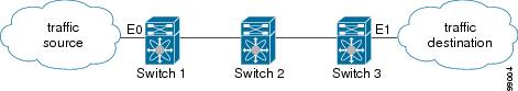
When you are trying to block traffic from source to destination, you can apply an inbound IP-ACL to E0 on Switch 1 instead of an outbound list to E1 on Switch 3.
Figure 22-3 Denying Traffic on the Inbound Interface
The access group controls access to an interface. Each interface can only be associated with one access list per direction. The ingress direction can have a different ACL than the egress direction. The access group becomes active on creation.
Tip
Caution
The terms in, out, source, and destination are used as referenced by the switch.
•
The access-group configuration for the ingress traffic applies to both local and remote traffic.
•
The access-group configuration for the egress traffic applies only to local traffic.
Using the log-deny option at the end of the individual ACL entries shows the ACL number and whether the packet was permitted or denied, in addition to port-specific information. This option causes an information logging message about the packet that matches the dropped entry (or entries).
For the input ACL, the log displays the raw MAC information. The keyword "MAC=" does not refer to showing an Ethernet MAC frame with MAC address information. It refers to the Layer 2 MAC-layer information dumped to the log. For the output ACL, the raw Layer 2 information is not dumped to the log.
The following is an example of an input ACL log dump.
Jul 17 20:38:44 excal-2%KERN-7-SYSTEM_MSG:%IPACL-7-DENY:IN=vsan1 OUT=
MAC=10:00:00:05:30:00:47:df:10:00:00:05:30:00:8a:1f:aa:aa:03:00:00:00:08:00:45:00:00:54:00
:00:40:00:40:01:0e:86:0b:0b:0b:0c:0b:0b:0b:02:08:00:ff:9c:01:15:05:00:6f:09:17:3f:80:02:01
:00:08:09:0a:0b:0c:0d:0e:0f:10:11:12:13:14:15:16:17:18:19:1a:1b:1c:1d:1e:1f:20:21:22:23:24
:25:26:27:28:29:2a:2b SRC=11.11.11.12 DST=11.11.11.2 LEN=84 TOS=0x00 PREC=0x00 TTL=64 ID=0
DF PROTO=ICMP TYPE=8 CODE=0 ID=277 SEQ=1280
The following is an example of an output ACL log dump.
Jul 17 20:38:44 excal-2%KERN-7-SYSTEM_MSG:%IPACL-7-DENY:IN= OUT=vsan1 SRC=11.11.11.2
DST=11.11.11.12 LEN=84 TOS=0x00 PREC=0x00 TTL=255 ID=38095 PROTO=ICMP TYPE=0 CODE=0 ID=277
SEQ=1280
Configuring IPFC
Once the VSAN interface is created, you can specify the IP address for that VSAN.
Configuring Overlay VSANs
VSANs enable deployment of larger SANs by overlaying multiple logical SANs, each running its own instance of fabric services, on a single large physical network. This partitioning of fabric services reduces network instability by containing fabric reconfiguration and error conditions within an individual VSAN. VSANs also provide the same isolation between individual VSANs as physically separated SANs. Traffic cannot cross VSAN boundaries and devices may not reside in more than one VSAN. Because each VSAN runs separate instances of fabric services, each VSAN has its own zone server and can be zoned in exactly the same way as SANs without VSAN capability.
To configure an overlay VSAN, follow these steps:
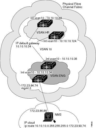
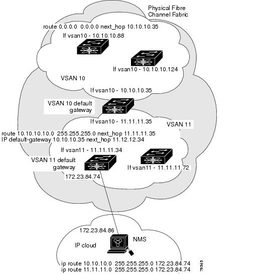
To configure the management interface displayed in Figure 22-4, set the default gateway to an IP address on the Ethernet network.
Step 1
Step 2
Step 3
Step 4
Figure 22-4 Overlay VSAN Configuration Example
Configuring Multiple VSANs
More than one VSAN can be used to segment the management network in multiple subnets. An active interface must be present on the switch for the VSAN interface to be enabled.
To configure an overlay VSAN, follow these steps:
Step 1
Step 2
Step 3
Step 4
Figure 22-5 Multiple VSANs Configuration Example
Managing IPFC Connectivity with Multiple VSANs
To configure IPFC from the Device Manager, choose VSAN from the FC menu and click the General tab.
Configuring VRRP
Cisco MDS 9000 Family switches are compliant with RFC 2338 standards for Virtual Router Redundancy Protocol (VRRP) features. This section provides details on the VRRP feature.
VRRP Features
VRRP provides a redundant alternative path to the gateway switch, which has connectivity to the NMS. VRRP has the following characteristics and advantages:
•
•
•
•
•
•
•
VRRP Functionality
In Figure 22-6, switch A is the VRRP master and switch B is the VRRP backup switch. Both switches have IP address to VRRP mapping configured. The other switches set switch A as the default gateway. If switch A fails, the other switches don't have to change the routing configurations as switch B automatically becomes the master and takes over the function of a gateway.
Figure 22-6 VRRP Functionality
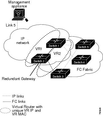
In Figure 22-7, the fabric example has two virtual router groups (VR1 and VR 2) because a virtual router cannot span across different types of interfaces. In both switch 1 and switch 2, the Ethernet interface is in VR 1 and the FC interface is in VR 2. Each virtual router is uniquely identified by the VSAN interface and the VR ID.
Figure 22-7 Redundant Gateway
Creating or Removing a Virtual Router
All VRRP configurations should be replicated across switches in a fabric that runs VRRP.
Enabling a Virtual Router
By default, a virtual router is always disabled (shutdown). VRRP can be configured only if this state is disabled. Be sure to configure at least one IP address before attempting to enable a VR.
Adding an IP Address for a Virtual Router
One primary IP address and multiple secondary addresses can be configured for a switch. If the configured IP address is the same as the interface IP address, this switch automatically owns the IP address.
Viewing IP Address Information
To view IP addresses of the switches in the current fabric from the Fabric Manager, choose Switches from the menu tree.
The Information pane displays IP address information for multiple switches.
Managing IP Addresses for VRRP
To manage IP addresses for virtual routers from Device Manager, follow these steps:
Step 1
Step 2
Step 3
Step 4
Setting Priority for the Virtual Router
The valid range to assign a virtual router priority is 1 to 254 with 1 being the lowest priority and 254 being the highest priority. The default value is 100 for switches with secondary IP addresses and 255 for a switch with the primary IP address.
Setting the Time Interval for the Advertisement Packet
The valid time range for an advertisement packet is between 1 and 255 seconds with the default being 1 (one) second. If the switch has the primary IP address, this time must be specified.
Preempting the Master Virtual Router
By default, the preempt option is enabled. An owner with priority 255 cannot be preempted. If two priorities match, the owner with the highest priority preempts the master virtual router.
The VRRP preempt option is not supported on IP storage Gigabit Ethernet interfaces. However, if the virtual IP address is also the IP address for the interface, then preemption is implicitly applied.
Configuring Authentication for the Virtual Router
VRRP security provides three options, including simple text authentication, MD5 authentication, and no authentication.
•
•
•
You can configure the key using the authentication option in the VRRP submode and distribute it using the configuration file. The security parameter index (SPI) settings assigned in this option should be unique for each VSAN.
All VRRP configurations must be duplicated
Setting the Priority Based on Interface State
The tracking feature is disabled by default. When you specify the tracking option, the priority of the virtual router is changed based on the state of another interface in the switch. When the tracked interface is down, the priority of the virtual router is changed to a lower priority value. When the tracked interface is up, the priority of the virtual router is restored to its original value. You can track one of two interfaces on a switch in the Cisco MDS 9000 Family: a specified VSAN interface or a management interface.
Configuring VRRP Operations Attributes
To configure VRRP operations attributes from Device Manager, follow these steps:
Step 1
Step 2
Step 3
Step 4
Default Settings
Table 22-3 lists the default settings for IP features.
Note
Enabling or Disabling IP Forwarding
To view or change the IP forwarding configuration of the switches in the current fabric, perform the following steps.
Step 1
Step 2
Viewing Information and Statistics
You can monitor a variety of information and statistics about IP services from Fabric Manager and Device Manager.
This section includes the following topics:
•
•
Viewing VRRP Statistics
To monitor VRRP statistics, click the Statistics tab on the VRRP dialog box. The VRRP dialog box with the Statistics tab selected is displayed.
Viewing TCP Information and Statistics
To view TCP information from the Device Manager, choose Mgmt TCP/UDP from the IP menu.
To monitor TCP statistics from the Fabric Manager, choose IP > Mgmt Statistics from the menu tree and click the TCP tab. To monitor TCP statistics from the Device Manager, choose Statistics from the IP menu and view the TCP tab.
Viewing UDP Information and Statistics
To view User Datagram Protocol (UDP) information, from the Device Manager, choose Mgmt TCP/UDP from the IP menu and click the UDP tab.
To monitor UDP traffic from the Fabric Manager, choose IP > Mgmt Statistics from the menu tree and click the UDP tab. From Device Manager, choose Statistics from the IP menu and click the UDP tab.
The Fabric Manager Information pane displays TCP traffic information for multiple switches. The Device Manager dialog box displays information for a single switch.
Viewing IP Statistics
To monitor IP statistics from the Fabric Manager, choose IP >Mgmt Statistics from the menu tree and click the IP tab. From Device Manager, select Statistics from the IP menu and click the IP tab.
The Fabric Manager Information pane displays IP statistics for multiple switches. The Device Manager dialog box displays information for a single switch.
Viewing ICMP Statistics
To monitor statistics for ICMP packets received, select IP > Mgmt Statistics from the menu tree and click the ICMP In tab. To monitor statistics for ICMP packets transmitted from the Fabric Manager, select IP > Mgmt Statistics from the menu tree and click the ICMP Out tab.
To monitor ICMP statistics from Device Manager, select Statistics from the IP menu and click the ICMP tab.
The Fabric Manager Information pane displays information for multiple switches. The Device Manager dialog box displays information for a single switch.
In the Device Manager, a prefix (In or Out) identifies whether the packets are received or transmitted. In the Fabric Manager, separate tabs on the Information pane are provided for incoming and outbound ICMP traffic and this prefix is omitted.