-
Cisco MDS 9000 Family Fabric Manager Configuration Guide, Release 1.3 (from Release 1.3(1) through Release 1.3(6))
-
Index
-
New and Changed Information
-
Preface
-
Product Overview
-
Getting Started with Cisco Fabric Manager
-
Overview of Fabric Manager Components
-
Before You Begin
-
Obtaining and Installing Licenses
-
Initial Configuration
-
Configuring High Availability
-
Software Images
-
Managing Modules
-
Managing System Hardware
-
Configuring and Managing VSANs
-
Configuring Interfaces
-
Configuring Trunking
-
Configuring PortChannels
-
Configuring and Managing Zones
-
Configuring Inter-VSAN Routing
-
Managing FLOGI, Name Server, FDMI, and RSCN Databases
-
Configuring Switch Security
-
Configuring Fabric Security
-
Configuring Port Security
-
Configuring Fibre Channel Routing Services and Protocols
-
Configuring IP Services
-
Configuring FICON
-
Configuring IP Storage
-
Configuring Call Home
-
Configuring Domain Parameters
-
Configuring Traffic Management
-
Configuring System Message Logging
-
Discovering SCSI Targets
-
Monitoring Network Traffic Using SPAN
-
Advanced Features and Concepts
-
Configuring Fabric Configuration Servers
-
Monitoring System Processes and Logs
-
Troubleshooting the Fabric
-
Troubleshooting Fabric Manager Issues
-
 Feedback
Table Of Contents
Using Valid Formats and Ranges
Before You Begin
This chapter lists the information you need to have before you begin using your MDS 9000 Switch. For information on setting up the switch and doing an initial configuration, refer to the Cisco MDS 9000 Family Configuration Guide.
This chapter contains the following topics:
•
Using Valid Formats and Ranges
About Flash Devices
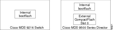
Every switch in the Cisco MDS 9000 Family contains one internal bootflash. The Cisco MDS 9500 Series additionally contains one external CompactFlash called slot0. (See Figure 4-1 and Figure 4-2.)
Figure 4-1 Flash Devices in the Cisco MDS 9000 Supervisor Module
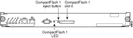
Figure 4-2 External CompactFlash in the Cisco MDS 9000 Supervisor Module
Internal bootflash:
All switches in the Cisco MDS 9000 Family have one internal bootflash: that resides in the supervisor or switching module.You have access to two directories within the internal bootflash: file system.
•
•
External CompactFlash (Slot0)
Cisco MDS 9500 Series directors contain an additional external CompactFlash called slot0:
The external CompactFlash, an optional device for MDS 9500 Series directors, can be used for storing software images, logs, and core dumps.
Switch Roles
By default, two roles exist in all switches:
•
•
When you execute a command, perform command completion, or obtain context sensitive help, the switch software allows the operation to progress if you have the correct permission as specified in the description of the command.
Using Valid Formats and Ranges
Note