-
Cisco MDS 9000 Family Fabric Manager Configuration Guide, Release 1.3 (from Release 1.3(1) through Release 1.3(6))
-
Index
-
New and Changed Information
-
Preface
-
Product Overview
-
Getting Started with Cisco Fabric Manager
-
Overview of Fabric Manager Components
-
Before You Begin
-
Obtaining and Installing Licenses
-
Initial Configuration
-
Configuring High Availability
-
Software Images
-
Managing Modules
-
Managing System Hardware
-
Configuring and Managing VSANs
-
Configuring Interfaces
-
Configuring Trunking
-
Configuring PortChannels
-
Configuring and Managing Zones
-
Configuring Inter-VSAN Routing
-
Managing FLOGI, Name Server, FDMI, and RSCN Databases
-
Configuring Switch Security
-
Configuring Fabric Security
-
Configuring Port Security
-
Configuring Fibre Channel Routing Services and Protocols
-
Configuring IP Services
-
Configuring FICON
-
Configuring IP Storage
-
Configuring Call Home
-
Configuring Domain Parameters
-
Configuring Traffic Management
-
Configuring System Message Logging
-
Discovering SCSI Targets
-
Monitoring Network Traffic Using SPAN
-
Advanced Features and Concepts
-
Configuring Fabric Configuration Servers
-
Monitoring System Processes and Logs
-
Troubleshooting the Fabric
-
Troubleshooting Fabric Manager Issues
-
 Feedback
Table Of Contents
Monitoring Network Traffic Using SPAN
Allowed Source Interface Types
Guidelines to Configure VSANs as a Source
Guidelines to Specifying Filters
Monitoring Traffic Using Fibre Channel Analyzers
Configuring Analyzers Using SPAN
Using a Single SD Port to Monitor Traffic
Configuration in the Source Switch
Configuration in All Intermediate Switches
Configuration in the Destination Switch
Single Source with One RSPAN Tunnel
Single Source with Multiple RSPAN Tunnels
Multiple Sources with Multiple RSPAN Tunnels
Monitoring Network Traffic Using SPAN
This chapter describes the switched port analyzer (SPAN) features provided in switches in the Cisco MDS 9000 Family. It includes the following sections:
This chapter contains the following topics:
•
Monitoring Traffic Using Fibre Channel Analyzers
About SPAN
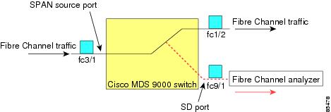
The switched port analyzer (SPAN) feature is specific to switches in the Cisco MDS 9000 Family. It monitors network traffic though a Fibre Channel interface. Traffic through any Fibre Channel interface can be replicated to a special port called the SPAN destination port (SD port). Any Fibre Channel port in a switch can be configured as an SD port. Once an interface is in SD-port mode, it cannot be used for normal data traffic. You can attach a Fibre Channel Analyzer to the SD port to monitor SPAN traffic.
SD ports do not receive frames, they merely transmit a copy of the SPAN source traffic. The SPAN feature is non-intrusive and does not affect switching of network traffic for any SPAN source ports.
Figure 30-1 SPAN Transmission
SPAN Sources
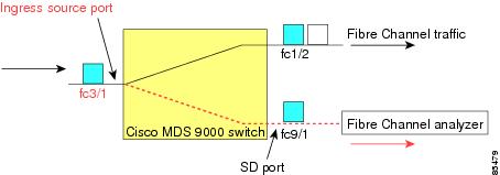
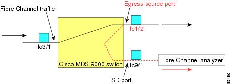
SPAN sources refer to the interfaces from which traffic can be monitored. You can also specify VSAN as a SPAN source, in which case, all supported interfaces in the specified VSAN are included as SPAN sources. You can choose the SPAN traffic in the ingress direction, the egress direction, or both directions for any source interface:
•
Figure 30-2 SPAN Traffic from the Ingress Direction
•
Figure 30-3 SPAN Traffic from Egress Direction
IPS Source Ports
Effective SAN-OS Release 1.3(x) Switched Port Analyzer (SPAN) capabilities are also available on the IP Storage Services (IPS) module. The SPAN feature is only implemented on the FCIP and iSCSI virtual Fibre Channel port interfaces, not the physical Gigabit Ethernet ports. You can SPAN ingress traffic, egress traffic, or traffic in both directions for all eight iSCSI and 24 FCIP interfaces that are available in the IPS module.
You can configure SPAN for Ethernet traffic using Cisco switches or routers connected to the Cisco MDS 9000 Family IPS modules.
CSM Source Ports
Effective SAN-OS Release 1.3(x) Switched Port Analyzer (SPAN) capabilities are also available on the Caching Services Module (CSM).
Refer to the Cisco MDS 9000 Family SAN Volume Controller Configuration Guide for further information.
Allowed Source Interface Types
The SPAN feature is available for the following interface types:
•
–
–
–
–
–
–
–
–
–
–
VSAN as a SPAN Source
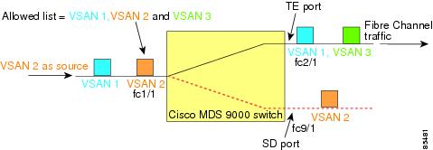
When a VSAN as a source is specified, then all physical ports and PortChannels in that VSAN are included as SPAN sources. A TE port is included only when the port VSAN of the TE port matches the source VSAN. A TE port is excluded even if the configured allowed VSAN list may have the source VSAN, but the port VSAN is different.
You cannot configure source interfaces (physical interfaces, PortChannels, or sup-fc interfaces) and source VSANs in the same SPAN session.
Guidelines to Configure VSANs as a Source
The following guidelines apply when configuring VSANs as a source:
•
•
•
•
–
–
–
Figure 30-4 VSAN As a SPAN Source
For the configuration shown in Figure 30-4, the following apply:
•
•
SPAN Sessions
Each SPAN session represents an association of one destination with a set of source(s) along with various other parameters that you specify to monitor the network traffic. One destination can be used by one or more SPAN sessions. You can configure up to 16 SPAN sessions in a switch. Each session can have several source ports and one destination port.
To activate a SPAN session, at least one source and the SD port must be up and functioning. Otherwise, traffic will not be directed to the SD port.
To temporarily deactivate (suspend) a SPAN session use the suspend command in the SPAN submode. The traffic monitoring is stopped during this time. You can reactivate the SPAN session using the no suspend command.
A source can be shared by two sessions, however, each session must be in a different direction—one ingress and one egress.
Creating SPAN Sessions
To create a SPAN session, follow these steps.
Step 1
Step 2
Step 3
Step 4
Step 5
Step 6
Step 7
Step 8
Step 9
Step 10
Editing SPAN Sources
To edit a SPAN source, follow these steps.
Step 1
Step 2
Step 3
Step 4
You see the Edit FC Interface Source dialog box.
Step 5
You see the Create FC Interface Source dialog box.
Step 6
Step 7
Step 8
Step 9
Deleting SPAN Sessions
To delete a SPAN session, perform the following steps.
Step 1
You see the SPAN dialog box.
Step 2
Step 3
Step 4
The SPAN session is deleted.
Specifying Filters
You can perform VSAN-based filtering to selectively monitor network traffic on specified VSANs. You can apply this VSAN filter to all sources in a session. Only VSANs present in the filter are spanned.
You can specify session VSAN filters which are applied to all sources in the specified session. These filters are bidirectional and apply to all sources configured in the session.
Guidelines to Specifying Filters
The following guidelines apply to SPAN filters:
•
•
•
SD Port Characteristics
An SD port has the following characteristics:
•
•
•
•
•
•
•
If you need to change a SD-port mode to another port mode, first remove the SD port from all sessions and then change the port mode using the switchport mode command.
•
•
•
Guidelines to Configure SPAN
The following guidelines apply for a SPAN configuration:
•
•
•
•
•
Monitoring Traffic Using Fibre Channel Analyzers
You can use SPAN to monitor traffic on an interface without any traffic disruption. This feature is specially useful in troubleshooting scenarios when traffic disruption changes the problem environment and makes it difficult to reproduce the problem.
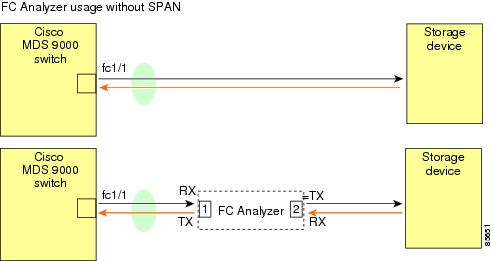
Without SPAN
You can monitor traffic using interface fc1/1 in a Cisco MDS 9000 Family switch that is connected to another switch or host. You need to physically connect a Fibre Channel analyzer between the switch and the storage device to analyze the traffic through interface fc1/1 as shown in Figure 30-5.
Figure 30-5 Fibre Channel Analyzer Usage Without SPAN
This type of connection has the following limitations:
•
•
•
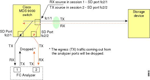
Using SPAN
Using SPAN, you can capture the same traffic scenario shown in Figure 30-5 without any traffic disruption. The Fibre Channel analyzer uses the ingress (rx) link at port 1 to capture all the frames going out of the interface fc1/1. It uses the ingress link at port 2, to capture all the ingress traffic on interface fc1/1.
Using SPAN you can monitor ingress traffic on fc1/1 at SD port fc2/2 and egress traffic on SD port fc2/1. This traffic is seamlessly captured by the FC analyzer as shown in Figure 30-6.
Figure 30-6 Fibre Channel Analyzer Using SPAN
Configuring Analyzers Using SPAN
To configure Fibre Channel Analyzers using SPAN for the example in Figure 30-6, follow these steps:
Step 1
Step 2
Step 3
Step 4
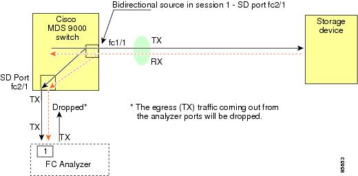
Using a Single SD Port to Monitor Traffic
You do not need to use two SD ports to monitor bidirectional traffic on any interface as shown in Figure 30-6. You can use one SD port and one FC analyzer port by monitoring traffic on the interface at the same SD port fc2/1.
Figure 30-7shows a SPAN setup where one session with destination port fc2/1 and source interface fc1/1 is used to capture traffic in both ingress and egress direction. This setup is more advantageous and cost-effective than the setup shown in Figure 30-6 because it uses one SD port and one port on the analyzer, instead of using a full, two-port analyzer.
Figure 30-7 Fibre Channel Analyzer Using a Single SD Port
To use this setup, the analyzer should have the capability of distinguishing ingress and egress traffic for all captured frames.
Default SPAN Settings
Table 30-1 lists the default settings for SPAN parameters
Remote SPAN
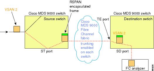
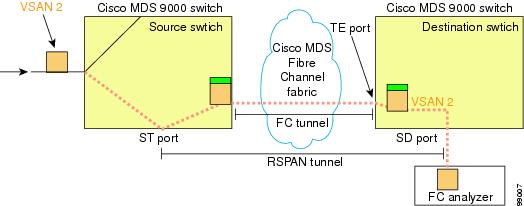
The Remote SPAN (RSPAN) feature enables you to remotely monitor traffic for one or more SPAN sources distributed in one or more source switches in a Fibre Channel fabric. The SPAN destination (SD) port is used for remote monitoring in a destination switch. A destination switch is usually different from the source switch(es) but is attached to the same Fibre Channel fabric. You can replicate and monitor traffic in any remote Cisco MDS 9000 Family switch or director, just as you would monitor traffic in a MDS source switch.
The RSPAN feature is nonintrusive and does not affect network traffic switching for any SPAN source ports. Traffic captured on the remote switch is tunneled across a Fibre Channel fabric which has trunking enabled on all switches in the path from the source switch to the destination switch. The Fibre Channel tunnel is structured using trunked ISL (TE) ports. In addition to TE ports, the RSPAN feature uses two other interface types:
•
•
Figure 30-8 RSPAN Transmission
Advantages to Using RSPAN
The RSPAN features has the following advantages:
•
•
•
•
•
FC and RSPAN Tunnels
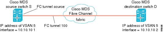
A FC tunnel is a logical data path between a source switch and a destination switch. The FC tunnel originates from the source switch and terminates at the remotely located destination switch.
RSPAN uses a special Fibre Channel tunnel (FC tunnel) that originates at the ST port in the source switch and terminates at the SD port in the destination switch. You must bind the FC tunnel to a ST port in the source switch and map the same FC tunnel to a SD port in the destination switch. Once the mapping and binding is configured, the FC tunnel is referred to as a RSPAN tunnel.
Figure 30-9 FC and RSPAN Tunnel
Guidelines to Configure RSPAN
The following guidelines apply for a SPAN configuration:
•
•
•
•
–
–
–
–
•
•
•
ST Port Characteristics
ST port have the following characteristics:
•
•
•
•
•
Configuring RSPAN
The RSPAN tunnel begins in the source switch and terminates in the destination switch. This section assumes Switch S to be the source and Switch D to be the destination.
Besides the source and destination switches, the VSAN must also be configured in each MDS switch in the Fibre Channel fabric, if they exist.
To monitor network traffic using the RSPAN feature, follow these steps:
Step 1
Step 2
Step 3
Step 4
Step 5
Step 6
Configuration in the Source Switch
This section identifies the tasks that must be performed in the source switch (Switch D).
This section contains the following topics:
Creating VSAN Interfaces
Figure 30-10 depicts a basic FC tunnel configuration.
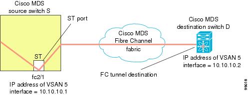
Figure 30-10 FC Tunnel Configuration
This example assumes that VSAN 5 is already configured in the VSAN database.
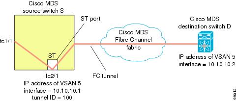
Configuring the ST Port
Once the FC tunnel is created, be sure to configure the ST port to bind it to the FC tunnel at the source switch. The FC tunnel becomes a RSPAN tunnel once the binding and mapping is complete. depicts a basic FC tunnel configuration.
Figure 30-11 Binding the FC Tunnel
ST ports cannot be configured using Advanced Services Modules (ASMs).
Configuration in All Intermediate Switches
This section identifies the tasks that must be performed in all intermediate switches in the end-to-end path of the RSPAN tunnel.
This section contains the following topics:
Configuring VSAN Interfaces
Figure 30-12 depicts an RSPAN tunnel configuration terminating in the destination switch (Switch D).
This example assumes that VSAN 5 is already configured in the VSAN database.
Enabling IP Routing
The IP routing feature is disabled by default. Be sure to enable IP routing in each switch (including the source and destination switches) in the end-to-end path in the fabric. This step is required to setup the FC tunnel.
Configuration in the Destination Switch
This section identifies the tasks that must be performed in the destination switch (Switch D).
This section contains the following topics:
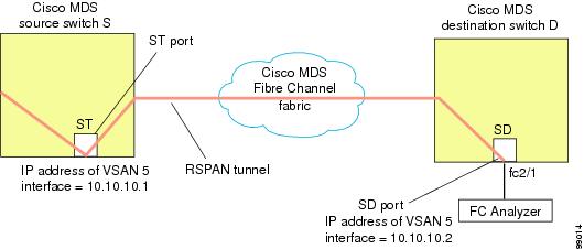
Configuring the SD Port
The SD port in the destination switch enables the FC Analyzer to receive the RSPAN traffic from the Fibre Channel tunnel. depicts a RSPAN tunnel configuration, now that tunnel destination is also configured.
Figure 30-12 RSPAN Tunnel Configuration
SD ports cannot be configured using Advanced Services Modules (ASMs).
Mapping the FC Tunnel
The tunnel-id-map option specifies the egress interface of the tunnel at the destination switch.
Figure 30-13 FC Tunnel Configuration
Configuring An Explicit Path
You can specify an explicit path through the Cisco MDS Fibre channel fabric (source-based routing), use the explicit-path option. For example, if you have multiple paths to a tunnel destination, you can use this option to specify the fc-tunnel to always take one path to the destination switch. The software then use this specified path even if other paths are available.
This option is especially useful if you prefer to direct the traffic through a certain path although other paths available. In a RSPAN situation, you can specify the explicit-path so the RSPAN traffic does not interfere with the existing user traffic. You can create any number of explicit paths in a switch.
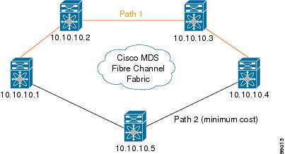
Figure 30-14 Explicit Path Configuration
The explicit path must be created in the source switch. To configure an explicit path, you must first create the path and then configure the use of any one path. If an explicit path is not configured, the minimum cost path is used by default. If an explicit path is configured and is functioning, the specified path is used.
This configuration explicitly specifies Path 1 to be used for the RSPAN traffic. Refer to RFC 3209 for further details on explicit paths and source based routing.
Monitoring RSPAN Traffic
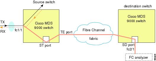
Once the session is configured, other SPAN sources for this session can also be configured as required. shows a RSPAN setup where one session with destination port fc2/1 and source interface fc1/1 is used to capture traffic in both ingress and egress direction.
Figure 30-15 Fibre Channel Analyzer Using a Single SD Port to Monitor RSPAN Traffic
To use this setup, the analyzer should have the capability of distinguishing ingress and egress traffic for all captured frames.
Sample Scenarios
RSPAN can be combined with the local SPAN feature so SD ports forward local SPAN traffic along with remote SPAN traffic. Various SPAN source and tunnel scenarios are described in this section.
Single Source with One RSPAN Tunnel
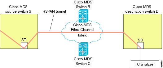
The source Switch S and the destination Switch D are interconnected through a Fibre Channel fabric. A RSPAN tunnel is configured as a destination interface for SPAN session and the ST port forwards SPAN traffic through the RSPAN tunnel.
Figure 30-16 RSPAN Scenario with One Source Switch, One Destination Switch, and One Tunnel
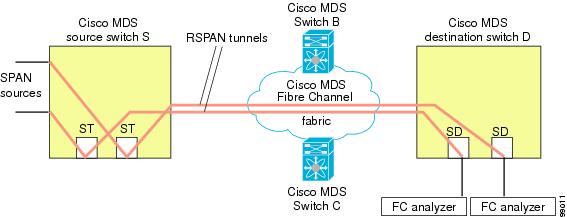
Single Source with Multiple RSPAN Tunnels
Figure 30-17 displays two separate RSPAN tunnels configured between Switches S and D. Each tunnel has an associated ST port in the source switch and a separate SD port in the destination switch. This configuration is useful for trouble shooting purposes.
Figure 30-17 RSPAN Scenario with One Source Switch, One Destination Switch, and Multiple Tunnels
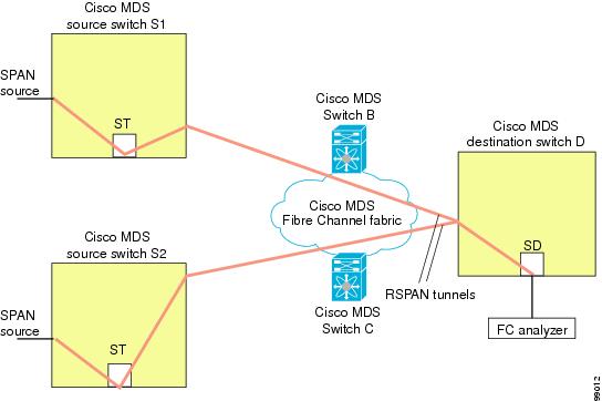
Multiple Sources with Multiple RSPAN Tunnels
Figure 30-18 displays two separate RSPAN tunnels configured between Switches S1 and S2. Both tunnels have an associated ST port in their respective source switch and terminate in the same SD port in the destination switch.
Figure 30-18 RSPAN Scenario with Two Source Switches, a Destination Switch, and Multiple Tunnels
This configuration is useful for remote monitoring purposes. For example, the administrator may be at the destination switch and can remotely monitor the two source switches.