-
Cisco MDS 9000 Family Fabric Manager Configuration Guide, Release 1.3 (from Release 1.3(1) through Release 1.3(6))
-
Index
-
New and Changed Information
-
Preface
-
Product Overview
-
Getting Started with Cisco Fabric Manager
-
Overview of Fabric Manager Components
-
Before You Begin
-
Obtaining and Installing Licenses
-
Initial Configuration
-
Configuring High Availability
-
Software Images
-
Managing Modules
-
Managing System Hardware
-
Configuring and Managing VSANs
-
Configuring Interfaces
-
Configuring Trunking
-
Configuring PortChannels
-
Configuring and Managing Zones
-
Configuring Inter-VSAN Routing
-
Managing FLOGI, Name Server, FDMI, and RSCN Databases
-
Configuring Switch Security
-
Configuring Fabric Security
-
Configuring Port Security
-
Configuring Fibre Channel Routing Services and Protocols
-
Configuring IP Services
-
Configuring FICON
-
Configuring IP Storage
-
Configuring Call Home
-
Configuring Domain Parameters
-
Configuring Traffic Management
-
Configuring System Message Logging
-
Discovering SCSI Targets
-
Monitoring Network Traffic Using SPAN
-
Advanced Features and Concepts
-
Configuring Fabric Configuration Servers
-
Monitoring System Processes and Logs
-
Troubleshooting the Fabric
-
Troubleshooting Fabric Manager Issues
-
 Feedback
Table Of Contents
Configuring Inter-VSAN Routing
Unique Domain ID Configuration Options
Creating IVR Zones and Zone Sets
Creating Additional IVR Zones and Zone Sets
Recovering an IVR Full Zone Database
Recovering an IVR Full Topology
IVR Using LUN Zoning or Read-Only Zoning
Configuring and Activating IVZs and IVZSs
Configuring Inter-VSAN Routing
This chapter explains the Inter-VSAN Routing (IVR) feature and provides details on sharing resources across VSANs using IVR management interfaces provided in the switch.
This chapter contains the following topics:
About IVR
Virtual SANs (VSANs) improve Storage Area Network (SAN) scalability, availability, and security by allowing multiple Fibre Channel SANs to share a common physical infrastructure of switches and ISLs. These benefits are derived from the separation of Fibre Channel services in each VSAN and isolation of traffic between VSANs. Data traffic isolation between the VSANs also inherently prevents sharing of resources attached to a VSAN, like robotic tape libraries. Using IVR, resources across VSANs are accessed without compromising other VSAN benefits.
Data traffic is transported between specific initiators and targets on different VSANs without merging VSANs into a single logical fabric. FC control traffic does not flow between VSANs, nor can initiators access any resource across VSANs aside from the designated ones. Valuable resources like tape libraries are easily shared across VSANs without compromise.
IVR is not limited to VSANs present on a common switch. Routes that traverse one or more VSANs across multiple switches can be established, if necessary, to establish proper interconnections. IVR used in conjunction with FCIP provides more efficient business continuity or disaster recovery solutions.
IVR Features
IVR has the following features:
•
Accesses resources across VSANs without compromising other VSAN benefits.
•
•
•
•
•
IVR Terminology
The terms used in this chapter are explained in this section.
•
•
•
•
•
•
An edge VSAN for one IVR path can be a transit VSAN for another IVR path.
•
When the source and destination edge VSANs are adjacent to each other, then a transit VSAN is not required between them.
•
•
IVR Guidelines
Before configuring an IVR SAN fabric, consider the following guidelines:
•
–
–
•
•
If you change any FSPF link cost, ensure that the FSPF path distance (that is, the sum of the link costs on the path) of any IVR path is less than 30,000.
IVR-enabled VSANs must be configured in no interop (default) mode or interop 1 mode.
Domain ID Guidelines
Domain IDs must be unique across inter-connected VSANs. To ensure unique domain IDs across inter-connected VSAN, follow these guidelines:
•
•
Transit VSANs Guidelines
Consider the following guidelines for transit VSANs:
•
–
–
•
•
Border Switch Guidelines
Before configuring border switches, consider the following guidelines:
•
•
•
•
•
Configuring IVR
To configure IVR in a SAN fabric, follow these steps.
Step 1
Step 2
Step 3
Step 4
Step 5
Unique Domain ID Configuration Options
You can configure domain IDs using one of two options:
•
•
Enabling IVR
The IVR feature must be enabled in all border switches in the fabric that participate in the IVR. By default, this feature is disabled in all switches in the Cisco MDS 9000 Family. To begin configuring the IVR feature, you must explicitly enable IVR on the required switches in the fabric.
The configuration and verification commands for the IVR feature are only available when IVR is enabled on a switch. When you disable this configuration, all related configurations are automatically discarded.
Configuring an IVR Topology
This section explains the process used to create an IVR topology.
Creating an IVR Topology
You must create the IVR topology in every IVR-enabled switch in the fabric. You can have up to 64 VSANs in an IVR topology. Specify the IVR topology using the following information:
•
•
•
The use of a single AF ID does not allow for segmented VSANs in an inter-VSAN topology.
Ensure to repeat this configuration in all IVR-enabled switches.
Transit VSANs are deduced based on your configuration The IVR feature does not have an explicit transit-VSAN configuration. In the example used above, VSAN 2 is the transit VSAN between VSANs 1 and 3.
Creating IVR Zones and Zone Sets
To create IVR zones or zone sets, perform the following steps:
Step 1
The Edit VSANxxx Local Full Zones window displays for the VSAN you selected.
Step 2
If you are adding a zone set, you can activate it by clicking the Activate button. This configuration is distributed to the other switches in the network fabric.
Note
Note
Note
Creating Additional IVR Zones and Zone Sets
To create additional zones and zone sets, follow these steps:
Step 1
Step 2
The zone is automatically added to the zone database.
Step 3
Step 4
The zone set is automatically added to the zone database.
Activating IVR Zone Sets
Once the zone sets have been created and populated, you must activate the zone set.
To activate an IVR zone set, follow these steps:
Step 1
Step 2
Note
Deactivating IVR Zone Sets
To activate a zone set, follow these steps:
Step 1
Step 2
Recovering an IVR Full Zone Database
You can recover an IVR zone database by copying the IVR full zone database.
To recover an IVR zone database, perform these steps.
Step 1
Step 2
Step 3
Step 4
Step 5
Step 6
Recovering an IVR Full Topology
You can recover a topology by copying the active zone database or the full zone database.
To recover a zone database, perform these steps.
Step 1
Step 2
Step 3
Step 4
Step 5
Step 6
IVR Interoperability
When using the IVR feature, all border switches in a given fabric must be Cisco MDS switches. However, other switches in the fabric may be non-MDS switches. For example, end devices that are members of the active IVZS may be connected to non-MDS switches. Non-MDS switches may also be present in the transit VSAN(s) or in the edge (VSANs) if the interop-mode 1 option is enabled.
IVR Using LUN Zoning or Read-Only Zoning
LUN-zoning and read-only zoning can be used between members of active IVR zones. To configure this service, you need to create and activate LUN-zones and/or read-only zones between the desired IVZ members in all relevant edge VSANs using the zoning interface.
The LUN zoning and read-only zoning features cannot be configured in a IVZS setup.
Creating IVZs and IVZSs
As part of the IVR configuration, you need to configure one or more IVZs to enable cross-VSAN communication. To achieve this result, you must specify each IVZ as a set of (pWWN, VSAN) entries. Like zones, several IVZs can be configured to belong to an IVRS. You can define several IVZSs and activate only one of the defined IVZSs.
The same IVZS must be activated on all the IVR-enabled switches.
Zones versus IVZs
Table 16-1 identifies the key differences between IVZs and Zones.
Automatic IVZ Creation
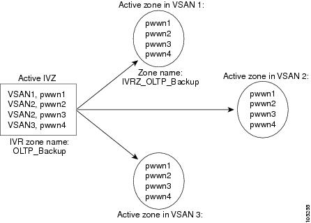
Figure 16-1 depicts an IVZ consisting of four members. To allow pwwn1 to communicate with pwwn2, they must be in the same zone in VSAN 1, as well as in VSAN 2. If they are not in the same zone, then the hard-zoning ACL entries will prohibit pwwn1 from communicating with pwwn2.
Figure 16-1 IVZ
A zone corresponding to each active IVZ is automatically created in each edge VSAN specified in the active IVZ. All pWWNs in the IVZ are members of these zones in each VSAN.
The zones are created automatically by the IVR process when an IVZS is activated. They are not stored in a full zone set database and are lost when the switch reboots or when a new zone set is activated. The IVR feature monitors these events and adds the zones corresponding to the active IVZS configuration when a new zone set is activated. Like zone sets, IVR zone sets are also activated non-disruptively.
If pwwn1 and pwwn2 are in an IVZ in the current as well as the new IVZS then activation of the new IVZS does not cause any traffic disruption between them.
Configuring and Activating IVZs and IVZSs
IVZ and IVZS names are restricted to 64 alphanumeric characters.
Using the force Option
Use the force option to activate the specified IVZS. Table 16-2 lists the various scenarios with and without the force option.
Using the force option of IVZS activation may cause traffic disruption, even for devices that are not involved in IVR. For example, if your configuration does not have any active zone sets and the default zone policy is permit, then an IVZS activation will fail. However, IVZS activation will go through if the force option is used. Since zones are created in the edge VSANs corresponding to each IVZ, traffic may be disrupted in edge VSANs where the default zone policy is permit.
Be sure to repeat this configuration in all border switches participating in the IVR configuration.
Using the Cisco MDS Fabric Manager, you can distribute IVZ configurations to all IVR-capable switches in the interconnected VSAN network. Refer to the Cisco MDS 9000 Family Fabric Manager User Guide for more information.
Clearing the IVZ Database
Clearing a zone set only erases the configured zone database, not the active zone database.
Using the Zone Wizard
Use the Zone Wizard to configure zones, read-only zones, and IVR zones.
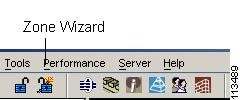
Step 1
Figure 16-2 Zone Wizard icon
The Zone Wizard displays.
Step 2