-
Cisco MDS 9000 Family Fabric Manager Configuration Guide, Release 1.3 (from Release 1.3(1) through Release 1.3(6))
-
Index
-
New and Changed Information
-
Preface
-
Product Overview
-
Getting Started with Cisco Fabric Manager
-
Overview of Fabric Manager Components
-
Before You Begin
-
Obtaining and Installing Licenses
-
Initial Configuration
-
Configuring High Availability
-
Software Images
-
Managing Modules
-
Managing System Hardware
-
Configuring and Managing VSANs
-
Configuring Interfaces
-
Configuring Trunking
-
Configuring PortChannels
-
Configuring and Managing Zones
-
Configuring Inter-VSAN Routing
-
Managing FLOGI, Name Server, FDMI, and RSCN Databases
-
Configuring Switch Security
-
Configuring Fabric Security
-
Configuring Port Security
-
Configuring Fibre Channel Routing Services and Protocols
-
Configuring IP Services
-
Configuring FICON
-
Configuring IP Storage
-
Configuring Call Home
-
Configuring Domain Parameters
-
Configuring Traffic Management
-
Configuring System Message Logging
-
Discovering SCSI Targets
-
Monitoring Network Traffic Using SPAN
-
Advanced Features and Concepts
-
Configuring Fabric Configuration Servers
-
Monitoring System Processes and Logs
-
Troubleshooting the Fabric
-
Troubleshooting Fabric Manager Issues
-
 Feedback
Table Of Contents
Display General NTP Statistics for a Switch
Edit an NTP Server or Peer Configuration
Initial Configuration
In order for Cisco MDS 9000 Family switches to be accessed by other devices, they must be initially configured. NTP information is part of this. For the rest of the information, refer to the "Initial Configuration" chapter in the Cisco MDS 9000 Family Configuration Guide.
This chapter contains the following topics:
•
Display General NTP Statistics for a Switch
•
NTP Configuration
A Network Time Protocol (NTP) server provides a precise time source (radio clock or atomic clock) to synchronize the system clocks of network devices. NTP is transported over User Datagram Protocol (UDP/IP). All NTP communications use UTC. An NTP server receives its time from a reference time source, such as a radio clock or atomic clock, attached to the time. NTP distributes this time across the network.
In a large enterprise network, having one time standard for all network devices is critical for management reporting and event logging functions when trying to correlate interacting events logged across multiple devices. Many enterprise customers with extremely mission-critical networks maintain their own stratum-1 NTP source.
Time synchronization happens when several frames are exchanged between clients and servers. The switches in client mode know the address of one or more NTP servers. The servers act as the time source and receive client synchronization requests.
By configuring an IP address as a peer, the switch will obtain and provide time as required. The peer is capable of providing time on its own and is capable of having a server configured. If both these instances point to different time servers, your NTP service will be more reliable. Thus, even if the active server link is lost, you can still maintain the right time due to the presence of the peer.
Note
If you only configure a peer, the most accurate peer takes on the role of the NTP server and the other peer(s) act as a peer(s). Both machines end at the right time if they have the right time source or if they point to the right NTP source.
NTP Configuration Guidelines
The following guidelines apply to all NTP configurations:
•
•
•
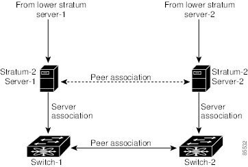
If the network is configured robustly, even a server down time will not affect well-configured switches in the network. displays a network with two NTP stratum 2 servers and two switches.
Figure 6-1 NTP Peer and Server Association
In this configuration, the switches were configured as explained below:
Display General NTP Statistics for a Switch
To display general NTP statistics for a switch, perform the following steps.
Step 1
In Fabric Manager, you see the System information pane. In Device Manager, you see the NTP dialog box.
Step 2
You see the general NTP statistics for that switch.
Create an NTP Server or Peer
To create an NTP server or peer, perform the following steps.
Step 1
In Fabric Manager, you see the System information pane. In Device Manager, you see the NTP dialog box.
Step 2
You see a list of NTP peers and servers for that switch.
Step 3
You see the Create NTP Peer dialog box.
Step 4
Step 5
Step 6
Step 7
The newly created peer or server is listed on the Peer tab.
Edit an NTP Server or Peer Configuration
To edit an NTP server or peer, perform the following steps.
Step 1
In Fabric Manager, you see the System information pane. In Device Manager, you see the NTP dialog box.
Step 2
You see a list of NTP peers and servers for that switch.
Step 3
Step 4
You see a drop-down list the options peer or server. Select the mode you want for the switch.
Step 5
Step 6
Delete an NTP Server or Peer
To delete an NTP server or peer, perform the following steps.
Step 1
In Fabric Manager, you see the System information pane. In Device Manager, you see the NTP dialog box.
Step 2
You see a list of NTP peers and servers for that switch.
Step 3
The Delete button is enabled.
Step 4