FlexPod as a Workload Domain for VMware Cloud Foundation
Available Languages
Bias-Free Language
The documentation set for this product strives to use bias-free language. For the purposes of this documentation set, bias-free is defined as language that does not imply discrimination based on age, disability, gender, racial identity, ethnic identity, sexual orientation, socioeconomic status, and intersectionality. Exceptions may be present in the documentation due to language that is hardcoded in the user interfaces of the product software, language used based on RFP documentation, or language that is used by a referenced third-party product. Learn more about how Cisco is using Inclusive Language.
- US/Canada 800-553-2447
- Worldwide Support Phone Numbers
- All Tools
 Feedback
 Feedback

In partnership with:
About the Cisco Validated Design Program
The Cisco Validated Design (CVD) program consists of systems and solutions designed, tested, and documented to facilitate faster, more reliable, and more predictable customer deployments. For more information, go to: http://www.cisco.com/go/designzone.
The FlexPod Datacenter solution is a validated approach for deploying Cisco® and NetApp technologies and products to build shared private and public cloud infrastructure. Cisco and NetApp have partnered to deliver a series of FlexPod solutions that enable strategic data-center platforms. The success of the FlexPod solution is driven through its ability to evolve and incorporate both technology and product innovations in the areas of management, compute, storage, and networking. This document explains the deployment details of incorporating FlexPod Datacenter as a workload domain for VMware Cloud Foundation. For an in-depth design discussion, refer the design guide: https://www.cisco.com/c/en/us/td/docs/unified_computing/ucs/UCS_CVDs/flexpod_vcf_design.html.
VMware Cloud Foundation provides a complete set of software defined services to run enterprise apps, both traditional and containerized, in private or public cloud environments. VMware Cloud Foundation simplifies the private cloud deployment and provides a streamlined path to the hybrid cloud by delivering a single integrated solution that is easy to deploy, operate and manage.
VMware Cloud Foundation (VCF) provides following benefits in a data center environment:
● Integrated Stack: VCF is an engineered solution that integrates the entire VMware software-defined stack with guaranteed interoperability.
● Standardized Architecture: VCF is built upon standard VMware Validated Design architecture and therefore ensures quick, repeatable deployments while eliminating risk of misconfigurations.
● Lifecycle Management: VCF includes lifecycle management services that automate day 0 to day 2 operations, resources provisioning and patching/upgrades.
Some of the key advantages of integrating Cisco FlexPod Datacenter as a workload domain for VMware Cloud Foundation are:
● Simpler and programmable infrastructure: FlexPod infrastructure delivered as infrastructure-as-a-code through a single partner integrable open API.
● Latest hardware and software compute innovations: policy-based configurations, delivered using Cisco Intersight, to deploy and manage the latest processor, memory, network, and power/cooling improvements.
● Storage Modernization: deliver high-speed, consistent, low latency, multi-tenant storage using a range of NetApp all-flash arrays.
● Innovative cloud operations: continuous feature delivery and no need for maintaining on-premises virtual machines supporting management functions.
● Built for investment protections: design ready for future technologies such as liquid cooling and high-Wattage CPUs; CXL-ready.
The FlexPod workload domain includes integration of the Cisco Intersight with VMware vCenter and NetApp Active IQ Unified Manager to deliver monitoring, orchestration, and workload optimization capabilities for different layers (virtualization and storage) of the FlexPod infrastructure. The modular nature of the Cisco Intersight platform also provides an easy upgrade path to additional services, such as Intersight Workload Optimization and Intersight Cloud Orchestrator.
Customers interested in understanding the FlexPod design and deployment details, including the configuration of various elements of design and associated best practices, should refer to Cisco Validated Designs for FlexPod, here: https://www.cisco.com/c/en/us/solutions/design-zone/data-center-design-guides/flexpod-design-guides.html.
This chapter contains the following:
● Audience
VMware Cloud Foundation enables data center administrators to provision an application environment in a quick, repeatable, and automated manner. VMware Cloud Foundation consists of workload domains which represent an application-ready infrastructure. A workload domain represents a logical unit that groups ESXi hosts managed by a vCenter Server instance with specific characteristics according to VMware best practices.
To deploy and manage the workload domains, VMware Cloud Foundation introduces VMware Cloud Builder and VMware Cloud Foundation Software Defined Data Center (SDDC) Manager. VMware Cloud Builder automates the deployment of the software defined stack, creating the first software defined unit known as the management domain. After the management domain is successfully setup, using the newly deployed SDDC Manager, virtual infrastructure administrator or cloud administrator provisions FlexPod Datacenter as a new workload domain to manage life cycle and other operational activities.
Workload domain definition requires administrators to configure network, compute and storage as well as install VMware vSphere ESXi software on the hosts that become part of workload domains (including the management domain). To automate the infrastructure setup, Cisco Intersight (or Cisco UCS Manager for Non-UCS-X-Series systems), NetApp ONTAP and Cisco NxOS configurations are (optionally) programmed using RedHat Ansible framework for an easy on-boarding experience.
The intended audience of this document includes but is not limited to IT architects, sales engineers, field consultants, professional services, IT managers, partner engineering, and customers who want to take advantage of an infrastructure built to deliver IT efficiency and enable IT innovation.
This document provides deployment guidance on following two key areas:
● Deploying VMware Cloud Foundation management domain on Cisco UCS C240 M5 servers managed using Cisco Intersight*.
● Configuring Cisco UCS X210c compute nodes in the FlexPod configuration and adding these FlexPod ESXi hosts to VMware Cloud Foundation as Virtual Infrastructure (VI) workload domain.
Note: *For deploying VMware Cloud Foundation management domain on UCSM managed Cisco UCS C240 M5 servers, please refer to Appendix C in this document.
While VMware Cloud Foundation can be utilized in public cloud such as VMware Cloud on AWS as well as hybrid cloud solutions, the discussion in this document focuses solely on the on-prem data center design and deployment. This document augments the FlexPod Datacenter with Cisco UCS X-Series Cisco Validated Design (CVD): https://www.cisco.com/c/en/us/td/docs/unified_computing/ucs/UCS_CVDs/flexpod_xseries_esxi7u2_design.html and explains new and changed information around VMware Cloud Foundation deployment. For a complete FlexPod configuration including various management components, refer to: https://www.cisco.com/c/en/us/td/docs/unified_computing/ucs/UCS_CVDs/flexpod_xseries_vmware_7u2.html.
The following elements distinguish this FlexPod Datacenter Cisco Validated Design from previous designs:
● VMware Cloud Foundation deployment on vSAN ready nodes.
● Integration of FlexPod Datacenter as a workload domain in VMware Cloud Foundation.
● Automated configuration of the ESXi hosts for both the VMware Cloud Foundation management and workload domains using Cisco Intersight.
Like all other FlexPod solution designs, FlexPod as a workload domain for VMware Cloud Foundation solution is configurable according to demand and usage. Customers can purchase exactly the infrastructure they need for their current application requirements and can then scale up by adding more resources to the FlexPod system or scale out by adding more FlexPod instances. By offloading the workload domain management to VMware Cloud Foundation and moving the infrastructure management into the cloud, the solution can respond to the speed and scale of customer deployments swiftly at cloud-scale.
Infrastructure as Code with Ansible to setup FlexPod and VCF Management Domain
This FlexPod solution provides a fully automated solution deployment that explains all components of the infrastructure. The configuration of the Cisco Network and Compute, NetApp ONTAP Storage, and VMware vSphere are automated by leveraging Ansible playbooks that have been developed to setup the components according to the solution best practices. Customers can use Ansible automation to configure the management domain servers as well as FlexPod Virtual Infrastructure (VI) domain servers, setup various required parameters (such as setting up NTP, enabling SSH, and so on) and present the servers for commissioning through VMware Cloud Foundation.
The automated deployment using Ansible provides a well-defined sequence of steps across the different elements of this solution. The automated deployment involves exchange of parameters or attributes between compute, network, storage, and virtualization and require some level of manual intervention. The workflow is clearly defined and documented for the customers. The Ansible playbooks to configure the different sections of the solution invoke a set of Roles which consume several user configurable variables. Based on the installation environment, customers can choose to modify the variables to suit their needs and proceed with the automated installation.
Note: The automation for ONTAP is scalable in nature that can configure anywhere from a single HA pair to a fully scaled 24 node ONTAP cluster.
After the FlexPod VI workload domain is onboarded, NetApp Management Tools such as ONTAP Tools for VMware vSphere (formerly Virtual Storage Console), SnapCenter Plug-in for VMware vSphere, and Active IQ Unified Manager can also be deployed in an automated fashion.
Deployment Hardware and Software
This chapter contains the following:
The FlexPod as a workload domain for VMware Cloud Foundation delivers a VMware Cloud Foundation VI workload domain solution built on Cisco UCS X-Series based FlexPod infrastructure.
To set up the VMware Cloud Foundation management domain, 4 Cisco UCS C240 M5 servers with vSAN certified components are utilized. VMware vSphere 7.0 U3 hypervisor is installed on M.2 boot optimized Solid State Drive (SSD) and vSAN is configured (by VMware Cloud Builder) as primary storage.
To set up the VMware Cloud Foundation VI workload domain, 3 UCS X210c compute nodes are utilized. VMware vSphere 7.0 U3 hypervisor is installed on the Fibre Channel (FC) LUNs hosted on NetApp A400 system. NetApp AFF A400 also provides Network File Storage (NFS) based primary storage for setting up the VMware infrastructure.
The Cisco UCS X-Series chassis and all the management rack servers are connected to single* pair of Cisco UCS 6454 Fabric Interconnects configured for Cisco Intersight Managed Mode (IMM).
Note: * Some customers might own Cisco UCS C-Series systems that are not supported in Intersight Managed Mode (IMM) because of unsupported components. These C-Series servers cannot be connected to the same Cisco UCS FIs where FlexPod Cisco UCS X-Series chassis is connected and will need to be connected to a separate pair of FIs which will be configured in Cisco UCSM mode. Cisco UCSM configuration for the management domain hosts (connected to a separate pair of Cisco UCS FIs) is covered in the appendix.
The FlexPod as a workload domain for VMware Cloud Foundation design meets the following general design requirements:
● Resilient design across all layers of the infrastructure with no single point of failure
● Scalable design with the flexibility to add compute capacity, storage, or network bandwidth as needed
● Modular design that can be replicated to expand and grow as the needs of the business grow
● Flexible design that can support different models of various components with ease
● Simplified design with ability to integrate and automate with VMware Cloud Foundation and other external automation tools
● Cloud-enabled design which can be configured, managed, and orchestrated from the cloud using GUI or APIs
FlexPod as a workload domain for VMware Cloud Foundation was validated using Fibre Channel (FC) boot from SAN configuration.
FlexPod Datacenter with Fibre Channel Design
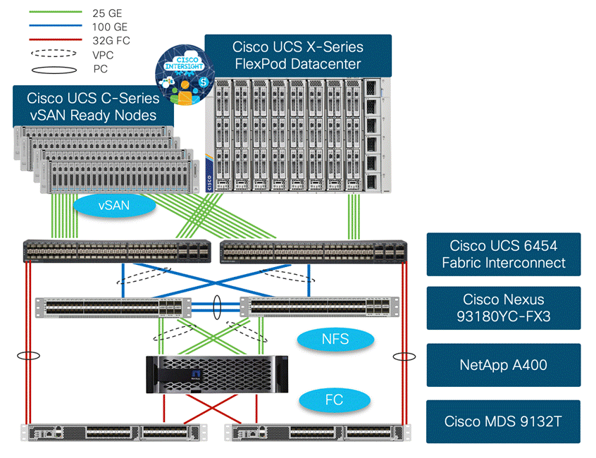
For the FC designs, NetApp AFF A400 and Cisco UCS X-Series are connected through Cisco MDS 9132T Fibre Channel Switches and boot from SAN for stateless compute uses the FC network. When adding FlexPod as VI workload domain, NFS storage setup as primary storage. The physical topology is shown in Figure 2.
The components are set up as follows:
● Cisco UCS 6454 Fabric Interconnects provide the rack server and chassis connectivity.
● 4 Cisco UCS C-Series* vSAN ready nodes are connected to fabric interconnects (FI) and are managed using Cisco Intersight. Two 25 Gigabit Ethernet ports from each Cisco UCS C-Series server are connected to each FI.
● The Cisco UCS X9508 Chassis connects to FIs using Cisco UCSX 9108-25G Intelligent Fabric Modules (IFMs), where four 25 Gigabit Ethernet ports are used on each IFM to connect to the appropriate FI. Remaining 4 ports from each IFM can be connected FIs if additional bandwidth is required.
● Cisco Nexus 93180YC-FX3 Switches in Cisco NX-OS mode provide the switching fabric.
● Cisco UCS 6454 Fabric Interconnect 100 Gigabit Ethernet uplink ports connect to Cisco Nexus 93180YC-FX3 Switches in a vPC configuration.
● The NetApp AFF A400 controller connects to the Cisco Nexus 93180YC-FX3 Switches using four 25 GE ports from each controller configured as a vPC for NFS traffic.
● For Cisco UCS to SAN connectivity, Cisco UCS 6454 Fabric Interconnects connect to the Cisco MDS 9132T switches using 32-Gbps Fibre Channel connections configured as a single port channel.
● For NetApp A400 SAN connectivity, each NetApp AFF A400 controller connects to both Cisco MDS 9132T switches using 32-Gbps Fibre Channel.
Note: * Since Cisco UCS C-series is being managed and configured by Cisco Intersight Managed Mode, the vSAN ready nodes must satisfy the software and hardware requirements outlined here: https://intersight.com/help/saas/supported_systems
VLAN Configuration
Table 1 lists VLANs configured for setting up the FlexPod environment along with their usage.
| VLAN ID |
Name |
Description |
Subnet |
| 2 |
Native-VLAN |
Use VLAN 2 as native VLAN instead of default VLAN (1) |
|
| 1010 |
OOB-Mgmt |
Existing management VLAN where all the management interfaces for various devices will be connected |
10.101.0.0/24 |
| 1011 |
IB-Mgmt |
FlexPod In-band management VLAN utilized for all in-band management connectivity such as ESXi hosts, VM management, and VCF components (Cloud Builder, SDDC Manager, all NSX managers, all vCenters) |
10.101.1.0/24 |
| 1012 |
VM-Traffic |
Application VLAN (one of many) where application VMs will be deployed. Adjust the name and add more VLANs as needed. |
10.101.2.0/24 |
| 1017 |
NFS |
VLAN for ESXi NFS datastore access in FlexPod VI workload domain |
10.101.7.0/24 |
| 3001 |
Mgmt-vSAN |
vSAN VLAN for the management domain |
192.168.1.0/24 |
| 3002 |
Mgmt-Host-Overlay |
NSX-T Host Overlay Network VLAN for the management domain |
192.168.2.0/24 |
| 3003 |
WD-Host-Overlay |
NSX-T Host Overlay Network VLAN for the FlexPod VI workload domain |
192.168.3.0/24 |
| 3030 |
vMotion |
Common vMotion VLAN for both management and VI workload domains |
192.168.31.0/24 |
Some of the key highlights of VLAN usage are as follows:
● VLAN 1010 is the management VLAN where out of band management interfaces of all the physical devices are connected.
● VLAN 1011 is used for in-band management of VMs, ESXi hosts, and other infrastructure services in the FlexPod environment. This VLAN is also used for deploying VMware Cloud Foundation components.
● VLAN 1017 provides FlexPod VI workload domain ESXi hosts access to the NSF datastores hosted on the NetApp Controllers. NFS storage is used as primary storage for VI domain.
● VLAN 3001 is used for VMware Cloud Foundation management domain vSAN configuration.
● VLANs 3002 and 3003 are separate NSX-T host overlay VLANs for VMware Cloud Foundation management and FlexPod VI workload domains. Depending on the customer requirements, a single VLAN can be used.
● VLAN 3030 is common VM vMotion VLAN for VMware Cloud Foundation management and FlexPod VI workload domains. Depending on the customer requirements, separate VLANs can be configured to isolate vMotion traffic.
Physical Components
Table 2 lists the required hardware components used to build the validated solution. Customers are encouraged to review their requirements and adjust the size or quantity of various components as needed.
Table 2. FlexPod as a workload domain for VMware Cloud Foundation hardware components
| Component |
Hardware |
Comments |
| Cisco Nexus Switches |
Two Cisco Nexus 93180YC-FX3 switches |
|
| Cisco MDS Switches |
Two Cisco MDS 9132T switches |
|
| NetApp A400 |
A NetApp AFF A400 with appropriate storage and network connectivity |
Customer requirements will determine the amount and type of storage. The NetApp A400 should support both 25Gbps (or 100 Gbps) ethernet and 32Gbps (or 16 Gbps) FC connectivity |
| Fabric Interconnects |
Two Cisco UCS 6454 Fabric Interconnects |
These fabric interconnects will be shared between the management and the workload domain |
| Management Domain Compute |
||
| Cisco UCS Servers |
A minimum of four Cisco UCS C-Series vSAN ready (or vSAN compatible) nodes |
vSAN ready nodes are recommended for ease of deployment however, customers can also utilize existing Cisco UCS C-Series servers with vSAN supported components |
| FlexPod VI Workload Domain Compute |
||
| Cisco UCS Chassis |
A minimum of one UCS X9508 chassis. |
Single chassis can host up to 8 Cisco UCS X210c compute nodes |
| Cisco UCS Compute Nodes |
A minimum of three Cisco UCS X210c compute nodes |
Four compute nodes are recommended but three compute nodes will work. |
Table 3 lists various software releases used in the solution.
Table 3. Software components and versions
| Component |
Version |
| Cisco Nexus 93180YC-FX3 |
9.3(10) |
| Cisco MDS 9132T |
9.2(2) |
| Cisco UCS Fabric Interconnects |
4.2(2c) |
| Cisco UCS C-Series vSAN ready nodes |
4.2(2a) |
| Cisco UCS X210c compute nodes |
5.0(2b) |
| Cisco Intersight Assist Appliance |
1.0.9-342 (will automatically upgrade to latest version when claimed in Cisco Intersight) |
| NetApp A400 - ONTAP |
9.11.1 |
| NetApp Active IQ Unified Manager |
9.11P1 |
| NetApp ONTAP tools |
9.11 |
| NetApp SnapCenter for vSphere |
4.7 |
| NetApp NFS plug-in for VAAI |
2.0 |
| VMware Cloud Foundation |
|
| Cloud Builder VM |
4.4.1 |
| SDDC Manager |
4.4.1 |
| VMware NSX-T |
3.1.3.7.4 |
| VMware vCenter |
7.0 Update 3d |
| VMware ESXi |
7.0 Update 3d |
| Cisco VIC FC Driver (nfnic) |
5.0.0.34 |
| Cisco VIC Ethernet Driver (nenic) |
1.0.42.0 |
This chapter contains the following:
● Create Port Channel Parameters
● Configure Virtual Port Channels
This chapter provides the procedure for configuring the Cisco Nexus 93180YC-FX3 switches used for ethernet LAN switching in this solution. The switch configuration for this validated design is based on the switching configuration covered in FlexPod Datacenter with Cisco UCS X-Series Cisco Validated Design (CVD): https://www.cisco.com/c/en/us/td/docs/unified_computing/ucs/UCS_CVDs/flexpod_xseries_vmware_7u2.html#NetworkSwitchConfiguration therefore this section only explains the changes to switching configuration from the base CVD.
Follow the physical connectivity guidelines for FlexPod as explained in section Physical Topology.
To set up the initial switch configuration, complete the steps explained here: https://www.cisco.com/c/en/us/td/docs/unified_computing/ucs/UCS_CVDs/flexpod_xseries_vmware_7u2.html#InitialConfiguration
To enable the required Cisco Nexus features, complete the steps explained here: https://www.cisco.com/c/en/us/td/docs/unified_computing/ucs/UCS_CVDs/flexpod_xseries_vmware_7u2.html#EnableNexusFeatures
To set up global configuration parameters, complete the steps explained here: https://www.cisco.com/c/en/us/td/docs/unified_computing/ucs/UCS_CVDs/flexpod_xseries_vmware_7u2.html#SetGlobalConfigurations
Procedure 1. Create VLANs on Cisco Nexus A and Cisco Nexus B
Refer to the VLAN information in Table 1 to set up all required VLANs.
Step 1. From the global configuration mode, run the following commands:
vlan <native-vlan-id for example 2>
name Native-Vlan
vlan <oob-mgmt-vlan-id for example 1010>
name OOB-Mgmt
vlan <ib-mgmt-vlan-id for example 1011>
name IB-Mgmt
vlan <application-vm-vlan-id for example 1012>
name VM-Traffic
vlan <NFS-vlan-id for example 1017>
name NFS
vlan <vsan-vlan-id for example 3001>
name Mgmt-vSAN
vlan <nsx-mgmt-host-overlay-vlan-id for example 3002>
name Mgmt-Host-Overlay
vlan <nsx-WorkloadDomain-host-overlay-vlan-id for example 3003>
name WD-Host-Overlay
vlan <vmotion-vlan-id for example 3030>
name vMotion
Note: Separate vMotion VLANs for management and VI workload domain can be configured for traffic isolation.
To set up Port Channels on both Nexus switches, complete the steps explained here: https://www.cisco.com/c/en/us/td/docs/unified_computing/ucs/UCS_CVDs/flexpod_xseries_vmware_7u2.html#CreatePortChannels
Create Port Channel Parameters
Procedure 1. Configure Port Channel Parameter on Cisco Nexus A and Cisco Nexus B
Step 1. From the global configuration mode, run the following commands to setup VPC Peer-Link port-channel:
interface Po10
switchport mode trunk
switchport trunk native vlan <native-vlan-id>
switchport trunk allowed vlan <oob-mgmt-vlan-id>, <ib-mgmt-vlan-id>, <application-vlan-id>, <nfs-vlan-id>, <vsan-vlan-id>, < nsx-mgmt-host-overlay-vlan-id>, < nsx-WorkloadDomain-host-overlay-vlan-id>, <vmotion-vlan-id>
spanning-tree port type network
Step 2. From the global configuration mode, run the following commands to setup port-channels for UCS FI 6454 connectivity:
interface Po11
switchport mode trunk
switchport trunk native vlan <native-vlan-id>
switchport trunk allowed vlan <oob-mgmt-vlan-id>, <ib-mgmt-vlan-id>, <vm-traffic-vlan-id>, <nfs-vlan-id>, <vsan-vlan-id>, < nsx-mgmt-host-overlay-vlan-id>, < nsx-WorkloadDomain-host-overlay-vlan-id>, <vmotion-vlan-id>
spanning-tree port type edge trunk
mtu 9216
!
interface Po12
switchport mode trunk
switchport trunk native vlan <native-vlan-id>
switchport trunk allowed vlan <oob-mgmt-vlan-id>, <ib-mgmt-vlan-id>, <vm-traffic-vlan-id>, <nfs-vlan-id>, <vsan-vlan-id>, < nsx-mgmt-host-overlay-vlan-id>, < nsx-WorkloadDomain-host-overlay-vlan-id>, <vmotion-vlan-id>
spanning-tree port type edge trunk
mtu 9216
Step 3. From the global configuration mode, run the following commands to setup port-channels for NetApp A400 connectivity:
interface Po113
switchport mode trunk
switchport trunk native vlan <native-vlan-id>
switchport trunk allowed vlan <ib-mgmt-vlan-id>, <infra-nfs-vlan-id>
spanning-tree port type edge trunk
mtu 9216
!
interface Po114
switchport mode trunk
switchport trunk native vlan <native-vlan-id>
switchport trunk allowed vlan <ib-mgmt-vlan-id>, <infra-nfs-vlan-id>
spanning-tree port type edge trunk
mtu 9216
Step 4. From the global configuration mode, run the following commands to setup port-channels for connectivity to existing management switch:
interface Po101
switchport mode trunk
switchport trunk native vlan <native-vlan-id>
switchport trunk allowed vlan <oob-mgmt-vlan-id>, <ib-mgmt-vlan-id>
spanning-tree port type network
mtu 9216
!
exit
copy run start
For fibre-optic connections between Cisco UCS Fabric Interconnects and Cisco Nexus 93180YC-FX3 switches, UDLD configuration is automatically enabled, and no additional configuration is required on either device.
Configure Virtual Port Channels
To set up Virtual Port Channel configuration on both Cisco Nexus switches, complete the steps explained here: https://www.cisco.com/c/en/us/td/docs/unified_computing/ucs/UCS_CVDs/flexpod_xseries_vmware_7u2.html#ConfigureVirtualPortChannels
VMware Cloud Foundation installation checks for gateways when configuring various VM Kernel ports on the ESXi hosts. If IP gateways for the VLANs covered below are present on the upstream switches, the configuration in this step can be skipped. If some or all the gateways are not configured, use Hot Standby Router Protocol (HSRP) and Switched Virtual Interface (SVI) on the Nexus switches to setup gateways for:
● Out-of-band management*
● In-band management*
● Application VM
● vSAN
● NSX host-overlay networks
Note: * Gateways for management networks will most likely be pre-configured in existing customer environments therefore exercise extreme caution when configuring new management IP gateways.
Procedure 1. Configure Nexus-A Switch
Step 1. From the global configuration mode, run the following commands to setup VPC Peer-Link port-channel:
feature interface-vlan
feature hsrp
interface Vlan1010
description GW for Out-of-Band Mgmt 10.101.0.0/24 Network
no shutdown
no ip redirects
ip address 10.101.0.251/24
no ipv6 redirects
hsrp version 2
hsrp 1010
preempt delay minimum 300
priority 105
ip 10.101.0.254
interface Vlan1011
description GW for In-band Management 10.101.1.0/24 Network
no shutdown
no ip redirects
ip address 10.101.1.251/24
no ipv6 redirects
hsrp version 2
hsrp 1011
preempt delay minimum 300
priority 105
ip 10.101.1.254
interface Vlan1012
description GW for Application VM Traffic 10.101.2.0/24 Network
no shutdown
! MTU should be adjusted based on application requirements
mtu 1500
no ip redirects
ip address 10.101.2.251/24
no ipv6 redirects
hsrp version 2
hsrp 1012
preempt delay minimum 300
priority 105
ip 10.101.2.254
interface Vlan1017
description GW for NFS 10.101.7.0/24 Network
no shutdown
mtu 9216
no ip redirects
ip address 10.101.7.251/24
no ipv6 redirects
hsrp version 2
hsrp 1017
preempt delay minimum 300
priority 105
ip 10.101.7.254
interface Vlan3001
description Gateway for Management Domain vSAN Network
no shutdown
mtu 9216
no ip redirects
ip address 192.168.1.251/24
no ipv6 redirects
hsrp version 2
hsrp 3001
preempt delay minimum 300
priority 105
ip 192.168.1.254
interface Vlan3002
description Gateway for NSX Management Domain Host Overlay VLAN
no shutdown
mtu 9216
no ip redirects
ip address 192.168.2.251/24
no ipv6 redirects
hsrp version 2
hsrp 3002
preempt delay minimum 300
priority 105
ip 192.168.2.254
interface Vlan3003
description Gateway for NSX Worload Domain Host Overlay VLAN
no shutdown
mtu 9216
no ip redirects
ip address 192.168.3.251/24
hsrp version 2
hsrp 3003
preempt delay minimum 300
priority 105
ip 192.168.3.254
interface Vlan3030
description Gateway for vMotion VLAN
no shutdown
mtu 9216
no ip redirects
ip address 192.168.30.251/24
no ipv6 redirects
hsrp version 2
hsrp 3030
preempt delay minimum 300
priority 105
ip 192.168.30.254
Procedure 2. Configure Nexus-B Switch
Step 1. From the global configuration mode, run the following commands to setup VPC Peer-Link port-channel:
feature interface-vlan
feature hsrp
interface Vlan1010
description GW for Out-of-Band Mgmt 10.101.0.0/24 Network
no shutdown
no ip redirects
ip address 10.101.0.252/24
no ipv6 redirects
hsrp version 2
hsrp 1010
ip 10.101.0.254
interface Vlan1011
description GW for In-band Management 10.101.1.0/24 Network
no shutdown
no ip redirects
ip address 10.101.1.252/24
no ipv6 redirects
hsrp version 2
hsrp 1011
ip 10.101.1.254
interface Vlan1012
description GW for Application VM Traffic 10.101.2.0/24 Network
no shutdown
! MTU should be adjusted based on application requirements
mtu 1500
no ip redirects
ip address 10.101.2.252/24
no ipv6 redirects
hsrp version 2
hsrp 1012
ip 10.101.2.254
interface Vlan1017
description GW for NFS 10.101.7.0/24 Network
no shutdown
mtu 9216
no ip redirects
ip address 10.101.7.252/24
no ipv6 redirects
hsrp version 2
hsrp 1017
ip 10.101.7.254
interface Vlan3001
description Gateway for Management Domain vSAN Network
no shutdown
mtu 9216
no ip redirects
ip address 192.168.1.252/24
no ipv6 redirects
hsrp version 2
hsrp 3001
ip 192.168.1.254
interface Vlan3002
description Gateway for NSX Management Domain Host Overlay VLAN
no shutdown
mtu 9216
no ip redirects
ip address 192.168.2.252/24
no ipv6 redirects
hsrp version 2
hsrp 3002
ip 192.168.2.254
interface Vlan3003
description Gateway for NSX Worload Domain Host Overlay VLAN
no shutdown
mtu 9216
no ip redirects
ip address 192.168.3.252/24
hsrp version 2
hsrp 3003
ip 192.168.3.254
interface Vlan3030
description Gateway for vMotion VLAN
no shutdown
mtu 9216
no ip redirects
ip address 192.168.30.252/24
no ipv6 redirects
hsrp version 2
hsrp 3030
ip 192.168.30.254
This chapter contains the following:
See section NetApp Hardware Universe for planning the physical location of the storage systems:
● Site Preparation
● System Connectivity Requirements
● Circuit Breaker, Power Outlet Balancing, System Cabinet Power Cord Plugs, and Console Pinout Requirements
● AFF Series Systems
To confirm that the hardware and software components that you would like to use are supported with the version of ONTAP that you plan to install, follow the steps at the NetApp Support site.
1. Access the HWU application to view the System Configuration guides. Click the Platforms menu to view the compatibility between different version of the ONTAP software and the NetApp storage appliances with your desired specifications.
2. Alternatively, to compare components by storage appliance, click Compare Storage Systems.
Follow the physical installation procedures for the controllers found here: https://docs.netapp.com/us-en/ontap-systems/index.html.
NetApp storage systems support a wide variety of disk shelves and disk drives. The complete list of disk shelves that are supported by the AFF A400 is available at the NetApp Support site.
When using SAS disk shelves with NetApp storage controllers, refer to: https://docs.netapp.com/us-en/ontap-systems/sas3/index.html for proper cabling guidelines.
When using NVMe drive shelves with NetApp storage controllers, refer to: https://docs.netapp.com/us-en/ontap-systems/ns224/index.html for installation and servicing guidelines.
Complete the NetApp A400 setup for Fibre Channel based storage access explained here: https://www.cisco.com/c/en/us/td/docs/unified_computing/ucs/UCS_CVDs/flexpod_xseries_vmware_7u2.html#StorageConfiguration
Note: Any iSCSI or FC-NVMe configuration sections can be skipped since this deployment only explains the Fibre Channel based storage design for FlexPod.
NetApp ONTAP Adaptive QoS Policy Groups (Optional)
The Adaptive QoS policy group can be used to automatically scale a throughput ceiling or floor to volume size, maintaining the ratio of IOPS to TBs|GBs as the size of the volume changes. You should be the cluster administrator to create a policy group.
Procedure 1. Create the Adaptive QoS Policy Group
Step 1. Create an adaptive QoS policy group:
A400::> qos adaptive-policy-group create -policy group adpg-app1 -vserver Infra-SVM -expected-iops 300iops/tb -peak-iops 1000iops/TB -peak-iops-allocation used-space -absolute-min-iops 50iops
Step 2. Apply an adaptive QoS policy group to a volume:
A400::> volume create -vserver Infra-SVM -volume app1 -aggregate aggr1 -size 2TB -qos-adaptive-policy-group adpg-app1
NetApp ONTAP Autonomous Ransomware Protection (Optional)
The Autonomous Ransomware Protection (ARP) feature uses workload analysis in NAS (NFS and SMB) environments to proactively detect and warn about abnormal activity that might indicate a ransomware attack. After suspecting an attack, ARP creates new snapshot copies in addition with the existing scheduled snapshot copies and the system take a volume Snapshot copy at that point in time and locks that copy. If the attack is confirmed later, the volume can be restored to this proactively taken snapshot, minimizing the data loss. If we are aware about the affected files and time of attack then it is possible to recover only those files from the snapshots copies rather than converting the whole volume. This feature is supported on ONTAP 9.10.1 onwards.
The command below provides an example configuration command to turn on ARP:
volume create -vserver Infra_svm -volume Infra_vol_1 -aggregate aggr1_node01 -state online -policy default -unix-permissions ---rwxr-xr-x -type RW -snapshot-policy default -foreground true -tiering-policy none -analytics-state off -activity-tracking-state off -anti-ransomware-state enabled
To get more details about ARP, go to: https://docs.netapp.com/us-en/ontap/anti-ransomware/index.html#ontap-ransomware-protection-strategy
At the completion of this step, NetApp A400 management connectivity, aggregate and volume configuration, logical interfaces (LIFs) for FC, NFS and management, and boot LUNs for three ESXi hosts that support boot from SAN using FC are ready.
Cisco Intersight Managed Mode – Initial Setup
This chapter contains the following:
● Set up Cisco Intersight Managed Mode on Cisco UCS Fabric Interconnects
● Set up Cisco Intersight Account
● Set up Cisco Intersight Licensing
● Set Up Cisco Intersight Resource Group
● Set Up Cisco Intersight Organization
● Claim Cisco UCS Fabric Interconnects in Cisco Intersight
● Upgrade Fabric Interconnect Firmware using Cisco Intersight
The Cisco Intersight managed mode (also referred to as Cisco IMM or Intersight managed mode) is a new architecture that manages Cisco Unified Computing System™ (Cisco UCS®) fabric interconnect–attached systems. Cisco Intersight managed mode standardizes both policy and operation management for Cisco UCS C-series M5 and Cisco UCSX X210c M6 compute nodes used in this deployment guide. For a complete list of supported platforms, visit: https://www.cisco.com/c/en/us/td/docs/unified_computing/Intersight/b_Intersight_Managed_Mode_Configuration_Guide/b_intersight_managed_mode_guide_chapter_01010.html
During the initial setup, Cisco UCS FIs are configured in Intersight Managed Mode and added to a newly created Intersight account. Intersight organization creation, resource group definition and license setup are also part of the initial setup. At the end of this section, customers can start creating various chassis and server level policies and profiles to deploy UCS compute nodes.
Set up Cisco Intersight Managed Mode on Cisco UCS Fabric Interconnects
To set up Cisco UCS 6454 Fabric Interconnects in Intersight Managed Mode, complete the steps here: https://www.cisco.com/c/en/us/td/docs/unified_computing/ucs/UCS_CVDs/flexpod_xseries_vmware_7u2.html#SetupCiscoIntersightManagedModeonCiscoUCSFabricInterconnects
Note: If a software version that supports Intersight Managed Mode (4.1(3) or later) is already installed on Cisco UCS Fabric Interconnects, do not upgrade the software to a recommended recent release using Cisco UCS Manager. The software upgrade will be performed using Cisco Intersight to make sure Cisco UCS X-series firmware is part of the software upgrade.
Set up Cisco Intersight Account
To set up a new Cisco Intersight Account, complete the steps here: https://www.cisco.com/c/en/us/td/docs/unified_computing/ucs/UCS_CVDs/flexpod_xseries_vmware_7u2.html#SetUpCiscoIntersightAccount
Note: Setting up a new Cisco Intersight account is not necessary if customers plan to add the Cisco UCS FIs to an existing account.
Set up Cisco Intersight Licensing
All new Cisco Intersight accounts need to be enabled for Cisco Smart Software Licensing. To set up Cisco Intersight licensing, complete the steps here: https://www.cisco.com/c/en/us/td/docs/unified_computing/ucs/UCS_CVDs/flexpod_xseries_vmware_7u2.html#SetupCiscoIntersightlicensing
Set Up Cisco Intersight Resource Group
A Cisco Intersight resource group is created where resources such as various targets will be logically grouped. A single resource group is created to host all the resources in this deployment. To configure a resource group, complete the steps here: https://www.cisco.com/c/en/us/td/docs/unified_computing/ucs/UCS_CVDs/flexpod_xseries_vmware_7u2.html#SetUpCiscoIntersightResourceGroup
Set Up Cisco Intersight Organization
All Cisco Intersight managed mode configurations including policies and profiles are defined under an organization. To define a new organization, complete the steps here: https://www.cisco.com/c/en/us/td/docs/unified_computing/ucs/UCS_CVDs/flexpod_xseries_vmware_7u2.html#SetUpCiscoIntersightOrganization
Note: This deployment guide uses an example organization “AA01” throughout the document.
Claim Cisco UCS Fabric Interconnects in Cisco Intersight
Before claiming the Cisco UCS Fabric Interconnects in Cisco Intersight, make sure the initial configuration for the fabric interconnects has been completed. To claim the Cisco UCS Fabric Interconnects, complete the steps here: https://www.cisco.com/c/en/us/td/docs/unified_computing/ucs/UCS_CVDs/flexpod_xseries_vmware_7u2.html#ClaimCiscoUCSFabricInterconnectsinCiscoIntersight
Upgrade Fabric Interconnect Firmware using Cisco Intersight
Cisco UCS Manager does not support Cisco UCS X-Series therefore Fabric Interconnect software upgrade performed using Cisco UCS Manager does not contain the firmware for Cisco UCS X-series. If Cisco UCS Fabric Interconnects are being converted from UCSM to Intersight Managed Mode, before setting up UCS domain profile and discovering the chassis, upgrade the Fabric Interconnect firmware to release 4.2(2c) (listed in Table 3) using Cisco Intersight by completing the steps here: https://www.cisco.com/c/en/us/td/docs/unified_computing/ucs/UCS_CVDs/flexpod_xseries_vmware_7u2.html#UpgradeFabricInterconnectFirmwareusingCiscoIntersight.
Note: If Cisco UCS Fabric Interconnects were upgraded to the latest recommended software using Cisco UCS Manager, this upgrade process through Intersight will still work and will copy the X-Series firmware to the Fabric Interconnects.
Cisco Intersight Managed Mode – Domain Profile Setup
This chapter contains the following:
● Review and Deploy the Domain Profile
● Configure Cisco UCS Chassis Profile (optional)
A Cisco UCS domain profile configures a fabric interconnect pair through reusable policies, allows configuration of the ports and port channels, and configures the VLANs and VSANs in the network. The domain-related policies can be attached to the profile either at the time of creation or later. One Cisco UCS domain profile can be assigned to one fabric interconnect domain.
The domain profile setup is comprised of the following:
● General configuration – name and organization assignment
● UCS Domain Assignment – assign previously claimed Cisco UCS Fabric Interconnects to the domain profile
● VLAN and VSAN configuration – define required VLANs and VSANs
● Port configuration – configure server and uplink ports and port-channels for Ethernet and FC traffic
● UCS domain configuration – policies such as NTP, DNS and QoS
● Review and deploy – review the configuration and deploy the UCS domain profile
To configure the name, description, and organization for the UCS domain profile, complete the steps here: https://www.cisco.com/c/en/us/td/docs/unified_computing/ucs/UCS_CVDs/flexpod_xseries_vmware_7u2.html#Step1General
To assign the Cisco UCS Fabric Interconnects to the UCS domain profile, complete the steps here: https://www.cisco.com/c/en/us/td/docs/unified_computing/ucs/UCS_CVDs/flexpod_xseries_vmware_7u2.html#Step2CiscoUCSDomainAssignment
To define the VLANs and VSANs, complete the steps here: https://www.cisco.com/c/en/us/td/docs/unified_computing/ucs/UCS_CVDs/flexpod_xseries_vmware_7u2.html#Step3VLANandVSANConfiguration.
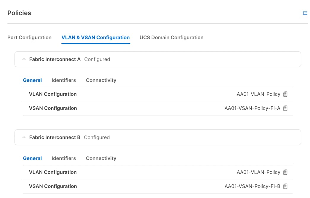
The VLAN are explained in Table 1. When the VLANs are successfully configured, Cisco Intersight displays a screen like Figure 3.
Define two separate VSANs for the SAN-A and SAN-B paths as covered in the link above. In this document, VSAN 101 and 102 were defined or SAN-A and SAN-B, respectively. The VSANs are not required for the VMware Cloud Foundation management domain deployment but are used in FlexPod VI workload domain for boot from SAN configuration.
Note: In this deployment, a single VLAN policy is shared by both Fabric Interconnects, but separate VSAN policies are defined for each Fabric Interconnect as shown in Figure 4.
To define the port roles and port-channels, complete the steps explained here: https://www.cisco.com/c/en/us/td/docs/unified_computing/ucs/UCS_CVDs/flexpod_xseries_vmware_7u2.html#Step3PortsConfiguration.
In this deployment, various port roles and associated port-channels used to connect to different devices are shown in Figure 2, Figure 5, and Figure 6 show various port roles and associated port-channel numbers as defined in Cisco Intersight.
To define the NTP server(s), DNS server(s), and to set the jumbo MTU for the best effort queue in QoS, complete the steps explained here:
Review and Deploy the Domain Profile
To verify the configuration and to deploy the domain profile, complete the steps explained here:
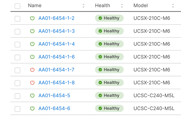
On successful deployment of the UCS domain profile, the ethernet port channels are enabled and the Cisco UCS rack servers and compute nodes are successfully discovered.
Configure Cisco UCS Chassis Profile (optional)
Cisco UCS Chassis profile in Cisco Intersight allow customers to configure various parameters for chassis, including:
● IMC Access Policy: IP configuration for the in-band chassis connectivity. This setting is independent of Server IP connectivity and only applies to communication to and from chassis.
● SNMP Policy, and SNMP trap settings.
● Power Policy to enable power management and power supply redundancy mode.
● Thermal Policy to control the speed of FANs.
A chassis policy can be assigned to any number of chassis profiles to provide a configuration baseline for a chassis. In this deployment, no chassis profile was created or attached but customers can configure some or all the policies and attach them to the chassis as needed. For more details on configuring Cisco UCS chassis policies, refer to: https://www.cisco.com/c/en/us/td/docs/unified_computing/Intersight/b_Intersight_Managed_Mode_Configuration_Guide/b_intersight_managed_mode_guide_chapter_01100.html
Cisco Intersight Managed Mode – Server Profile Template
This chapter contains the following:
● vNIC and vHBA Placement for Server Profile Templates
● Server Profile Template Creation
● Derive Management Domain Server Profile
● Derive VI Workload Domain Server Profile
In Cisco Intersight Managed Mode, a server profile enables resource management by simplifying policy alignment and server configuration. The server profiles are derived from a server profile template. Server profile template and its associated policies can be created using the server profile template wizard.
In this deployment, two separate server profile templates are created for VMware Cloud Foundation management hosts and FlexPod VI workload domain hosts because of several differences in the two types of hosts. The two server profile templates both share certain elements such as UUID pools, management access policies, adapter policies etc. but have some unique configurations such as boot policy, BIOS policy and LAN/SAN connectivity policy.
Note: This section explains the configuration of both types of server profile templates. Customers can deploy one or both templates depending on their environment.
vNIC and vHBA Placement for Server Profile Templates
This section explains the vNIC and vHBA definitions and placement for both types of server profile templates.
Management Domain Host vNIC Placement
Four vNICs are configured and manually placed as listed in Table 4.
Table 4. vNIC placement for Management Domain hosts
| vNIC/vHBA Name |
Slot |
Switch ID |
PCI Order |
| 00-VDS01-A |
MLOM |
A |
0 |
| 01-VDS01-B |
MLOM |
B |
1 |
| 02-VDS02-A |
MLOM |
A |
2 |
| 03-VDS02-B |
MLOM |
B |
3 |
FlexPod VI Workload Domain Host vNIC and vHBA Placement
Four vNICs and two vHBAs are configured and manually placed as listed in Table 5.
Table 5. vHBA and vNIC placement for FlexPod VI workload domain FC connected storage
| vNIC/vHBA Name |
Slot |
Switch ID |
PCI Order |
| 00-VDS01-A |
MLOM |
A |
0 |
| 01-VDS01-B |
MLOM |
B |
1 |
| 02-VDS02-A |
MLOM |
A |
2 |
| 03-VDS02-B |
MLOM |
B |
3 |
| vHBA-A |
MLOM |
A |
4 |
| vHBA-B |
MLOM |
B |
5 |
Server Profile Template Creation
The following two server profiles templates will be configured for this deployment:
● Management Domain host template
● FlexPod VI workload domain template
Procedure 1. Configure a Server Profile Template
Step 1. Log in to the Cisco Intersight.
Step 2. Go to Infrastructure Service > Configure > Templates and in the main window click Create UCS Server Profile Template.
Procedure 2. General Configuration
Step 1. Select the organization from the drop-down list (for example, AA01).
Step 2. Provide a name for the server profile template. The names used in this deployment are:
● VCF-MgmtHost-Template (UCS C240 M5 management hosts)
● AA01-WD-FC-Boot-Template (FlexPod FC boot from SAN)
Step 3. Select UCS Server (FI-Attached).
Step 4. Provide an optional description.
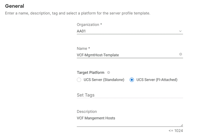
Step 5. Click Next.
Procedure 3. Compute Configuration – UUID Pool
Step 1. Click Select Pool under UUID Pool and then in the pane on the right, click Create New.
Step 2. Verify correct organization is selected from the drop-down list (for example, AA01) and provide a name for the UUID Pool (for example, AA01-UUID-Pool).
Step 3. Provide an optional Description and click Next.
Step 4. Provide a UUID Prefix (for example, a random prefix of AA010000-0000-0001 was used).
Step 5. Add a UUID block.
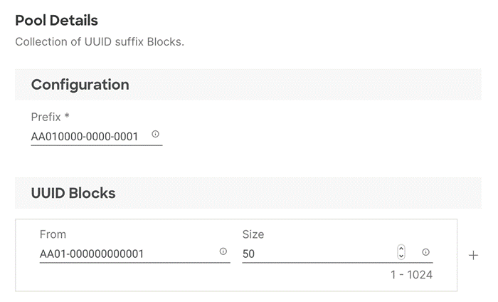
Step 6. Click Create.
Procedure 4. Compute Configuration – BIOS policy
Note: Since the management hosts in this deployment are Cisco UCS C240 M5 servers while the VI workload domain servers are Cisco UCS X210c M6 servers, different BIOS policies will be created for each of the server profile templates.
Step 1. Click Select Policy next to BIOS and in the pane on the right, click Create New.
Step 2. Verify correct organization is selected from the drop-down list (for example, AA01) and provide a name for the policy (for example, AA01-M5-BIOS-Policy or AA01-M6-BIOS-Policy).
Step 3. Click Next.
Step 4. On the Policy Details screen, select appropriate values for the BIOS settings. In this deployment, the BIOS values were selected based on “Virtualization” workload recommendations in the performance tuning guide for Cisco UCS servers. Use the settings listed below:
Procedure 5. Configure M6 Server BIOS Policy
For detailed information, see: https://www.cisco.com/c/en/us/products/collateral/servers-unified-computing/ucs-b-series-blade-servers/performance-tuning-guide-ucs-m6-servers.html
Step 1. Set the parameters below and leave all other parameters set to “platform-default.”
● Memory > NVM Performance Setting: Balanced Profile
● Power and Performance > Enhanced CPU Performance: Auto
● Processor > Energy Efficient Turbo: enabled
● Processor > Processor C1E: enabled
● Processor > Processor C6 Report: enabled
● Server Management > Consistent Device Naming: enabled
Procedure 6. Configure UCS M5 Server BIOS Policy
For detailed information, see: https://www.cisco.com/c/en/us/products/collateral/servers-unified-computing/ucs-b-series-blade-servers/white-paper-c11-744678.html
Step 1. Set the parameters below and leave all other parameters set to “platform-default.”
● Memory > NVM Performance Setting: Balanced Profile
● Processor > Power Technology: custom
● Processor > Processor C1E: disabled
● Processor > Processor C3 Report: disabled
● Processor > Processor C6 Report: disabled
● Processor > CPU C State: disabled
● Server Management > Consistent Device Naming: enabled
Step 2. Click Create.
Procedure 7. Compute Configuration - Boot Order policy for Management Domain hosts
Note: Management hosts are equipped with Cisco UCS Boot Optimized M.2 drive where ESXi will be installed for local boot. The policy explained below might need to be adjusted if customers have a different hard disk configuration or boot drive. The FC boot order policy for VI workload domain is different and is explained in the next procedure.
Step 1. Click Select Policy next to BIOS Configuration and then, in the pane on the right, click Create New.
Step 2. Verify correct organization is selected from the drop-down list (for example, AA01) and provide a name for the policy (for example, Local-BootOrder-Pol).
Step 3. Click Next.
Step 4. For Configured Boot Mode option, select Unified Extensible Firmware Interface (UEFI).
Step 5. Turn on Enable Secure Boot.
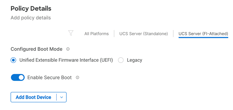
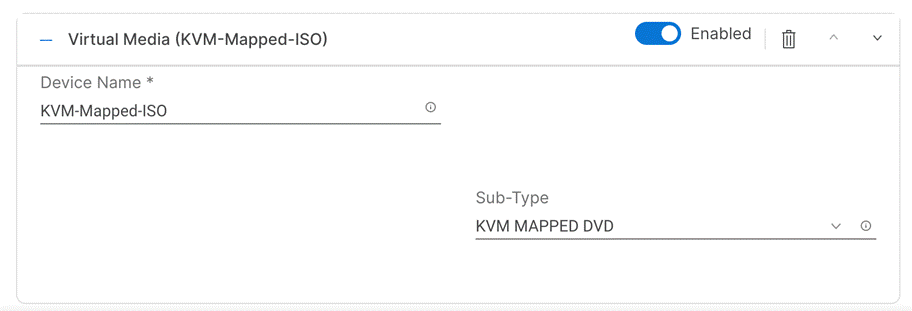
Step 6. Click Add Boot Device drop-down list and select Virtual Media.
Step 7. Provide a device name (for example, KVM-Mapped-ISO) and then, for the subtype, select KVM Mapped DVD.
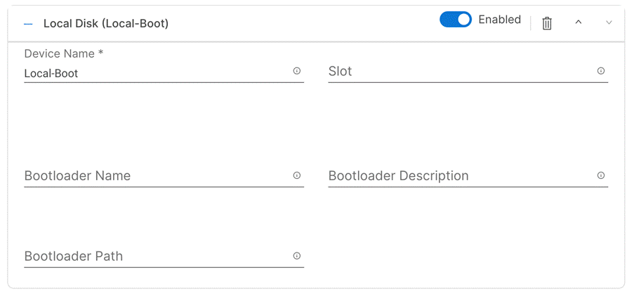
Step 8. From the Add Boot Device drop-down list, select Local Disk.
Step 9. Provide the Device Name (for example Local-Boot).
Step 10. Verify the order of the boot policies and adjust the boot order, as necessary.
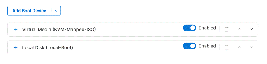
Step 11. Click Create.
Procedure 8. Compute Configuration - Boot Order policy for VI Workload Domain hosts
Step 1. Click Select Policy next to BIOS Configuration and then, in the pane on the right, click Create New.
Step 2. Verify correct organization is selected from the drop-down list (for example, AA01) and provide a name for the policy (for example, FC-BootOrder-Pol).
Step 3. Click Next.
Step 4. For Configured Boot Mode option, select Unified Extensible Firmware Interface (UEFI).
Step 5. Turn on Enable Secure Boot.

Step 6. Click Add Boot Device drop-down list and select Virtual Media.
Step 7. Provide a device name (for example, KVM-Mapped-ISO) and then, for the subtype, select KVM Mapped DVD.

For Fibre Channel SAN boot, all four NetApp controller LIFs will be added as boot options. The four LIFs are named as follows:
● FCP-LIF01a: NetApp Controller 1, LIF for Fibre Channel SAN A
● FCP-LIF01b: NetApp Controller 1, LIF for Fibre Channel SAN B
● FCP-LIF02a: NetApp Controller 2, LIF for Fibre Channel SAN A
● FCP-LIF02b: NetApp Controller 2, LIF for Fibre Channel SAN B
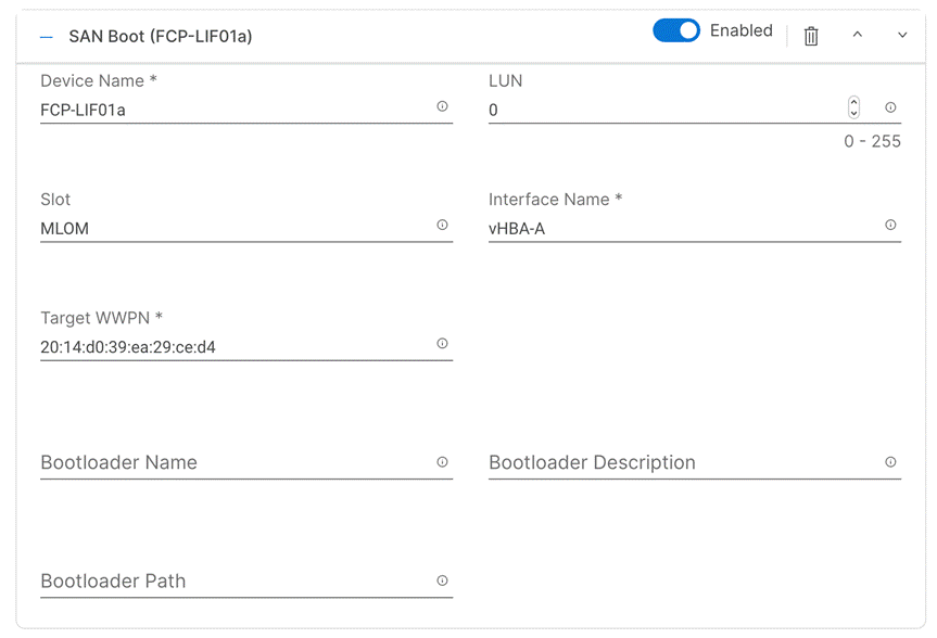
Step 8. From the Add Boot Device drop-down list, select SAN Boot.
Step 9. Provide the Device Name: FCP-LIF01a and the Logical Unit Number (LUN) value (for example, 0).
Step 10. Provide an interface name (for example, vHBA-A or vHBA-B). This value is important and should match the appropriate vHBA name for SAN-A or SAN-B.
Note: vHBA-A is used to access FCP-LIF01a and FCP-LIF02a and vHBA-B is used to access FCP-LIF01b and FCP-LIF02b.
Step 11. Add the appropriate World Wide Port Name (WWPN) of NetApp FCP LIFs as the Target WWPN.
Note: To obtain the WWPN values, log into NetApp controller using SSH and enter the following command: network interface show -vserver Infra-SVM -data-protocol fcp.
Step 12. Repeat steps 8-11 three more times to add all the remaining NetApp LIFs.
Step 13. Verify the order of the boot policies and adjust the boot order as necessary using arrows next to delete button.
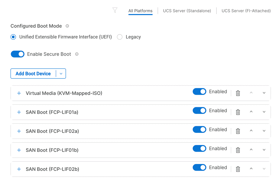
Step 14. Click Create.
Procedure 9. Compute Configuration – Configure Virtual Media Policy
This procedure enables you to configure the Virtual Media Policy to allow mapping an ISO file as installation source for operating system.
Step 1. Click Select Policy next to Virtual Media and then, in the pane on the right, click Create New.
Step 2. Verify correct organization is selected from the drop-down list (for example, AA01) and provide a name for the policy (for example, AA01-vMedia-Policy).
Step 3. Turn on Enable Virtual Media, Enable Virtual Media Encryption, and Enable Low Power USB.
Step 4. Do not Add Virtual Media at this time.
Step 5. Click Create.
Step 6. Click Next to move to Management Configuration.
Management Configuration
The following four policies will be added to the management configuration:
● IMC Access to define the pool of IP addresses for compute node KVM access
● IPMI Over LAN to allow Intersight to manage IPMI messages
● Local User to provide local administrator to access KVM
● Virtual KVM to allow the Tunneled KVM
Procedure 10. Management Configuration - Cisco IMC Access Policy
Step 1. Click Select Policy next to IMC Access and then, in the pane on the right, click Create New.
Step 2. Verify correct organization is selected from the drop-down list (for example, AA01) and provide a name for the policy (for example, AA01-IMC-Access-Policy).
Step 3. Click Next.
Note: Customers can select in-band management access to the compute node using an in-band management VLAN (for example, VLAN 1011) or out-of-band management access via the Mgmt0 interfaces of the FIs. In-band management access was configured in this deployment guide.
Step 4. Enable In-Band Configuration and provide the in-band management VLAN (for example, 1011).
Step 5. Make sure IPv4 address configuration is selected.
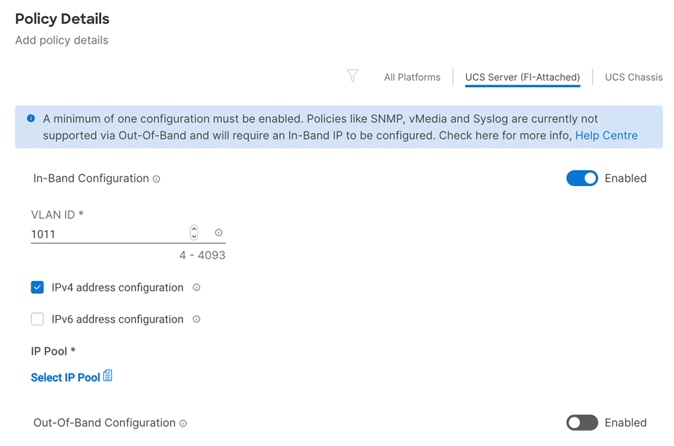
Step 6. Under IP Pool, click Select IP Pool and then, in the pane on the right, click Create New.
Step 7. Verify correct organization is selected from the drop-down list (for example, AA01) and provide a name for the pool (for example, AA01-Mgmt-IP-Pool).
Step 8. Select Configure IPv4 Pool and provide the information to define a pool for KVM IP address assignment including an IP Block.
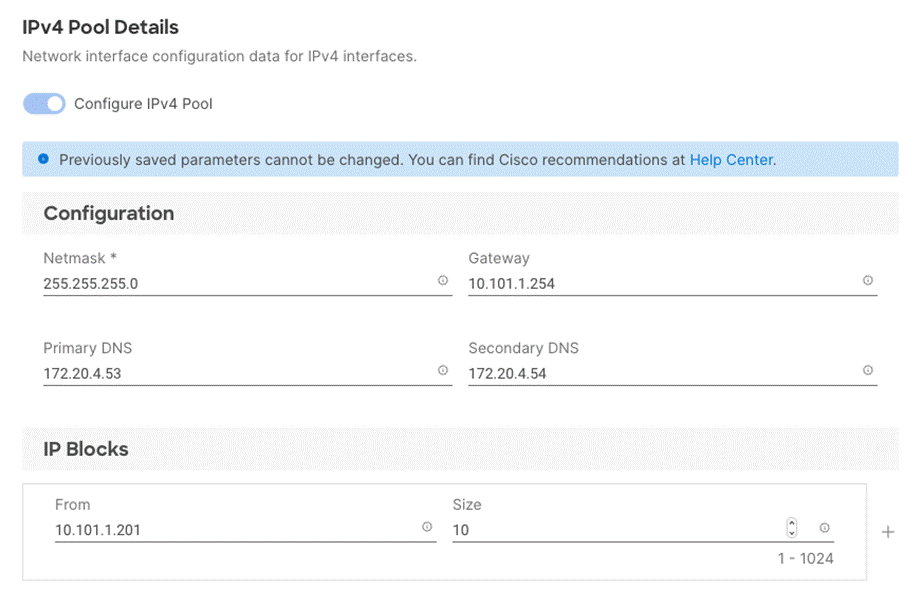
Note: The management IP pool subnet should be routable from the host that is trying to access the KVM session. In the example shown here, the hosts trying to establish an KVM connection would need to be able to route to 10.101.1.0/24 subnet.
Step 9. Click Next.
Step 10. Unselect Configure IPv6 Pool.
Step 11. Click Create to finish configuring the IP address pool.
Step 12. Click Create to finish configuring the IMC access policy.
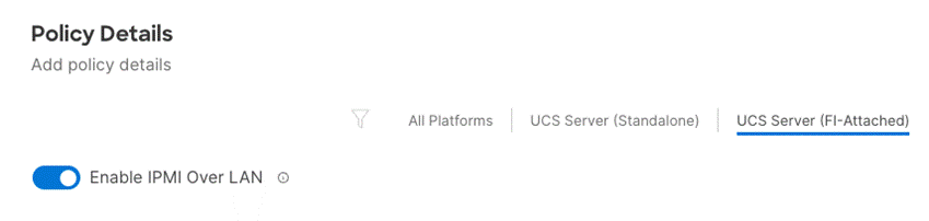
Procedure 11. Management Configuration - IPMI Over LAN policy
Step 1. Click Select Policy next to IPMI Over LAN and then, in the pane on the right, click Create New.
Step 2. Verify correct organization is selected from the drop-down list (for example, AA01) and provide a name for the policy (for example, AA01-Enable-IPMIoLAN-Policy).
Step 3. Turn on Enable IPMI Over LAN.
Step 4. Click Create.
Procedure 12. Management Configuration - Local User policy
Step 1. Click Select Policy next to Local User and the, in the pane on the right, click Create New.
Step 2. Verify correct organization is selected from the drop-down list (for example, AA01) and provide a name for the policy (for example, AA01-LocalUser-Pol).
Step 3. Verify that UCS Server (FI-Attached) is selected.
Step 4. Verify that Enforce Strong Password is selected.
Step 5. Click Add New User and then click + next to the New User.
Step 6. Provide the username (for example, fpadmin), select a role (for example, admin), and provide a password.
Note: The username and password combination defined here can be used to log into KVMs as well as for IPMI access. The default admin user and password also allow customers to log into KVM.
Step 7. Click Create to finish configuring the user.
Step 8. Click Create to finish configuring local user policy.
Step 9. Click Next to move to Storage Configuration.
Procedure 13. Management Configuration - Virtual KVM Policy
Step 1. Click Select Policy next to Virtual KVM and then, in the pane on the right, click Create New.
Step 2. Verify correct organization is selected from the drop-down list (for example, AA01) and provide a name for the policy (for example, AA01-KVM-Policy).
Step 3. Verify that UCS Server (FI-Attached) is selected.
Step 4. Turn on Allow Tunneled vKVM and leave the other two options on as well.
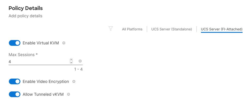
Step 5. Click Create.
Note: To enable Tunneled KVM, make sure under System > Settings > Security and Privacy>Configure, “Allow Tunneled vKVM Launch” and “Allow Tunneled vKVM Configuration” is turned on.
Step 6. Click Next to move to Storage Configuration.
Procedure 14. Storage Configuration
The Cisco UCS C240 M5 management hosts used in this deployment contain:
● A single M.2 drive for ESXi installation
● An SSD drive for caching tier
● Multiple HDDs for capacity tier
No special configuration (such as RAID) is needed for the M.2 drive and all the SSDs and HDDs are presented to operating system in JBOD configuration. VMware vSAN configures the caching and capacity disks as needed for vSAN setup. Figure 8 shows a sample SSD/HDD configuration used in the validation environment. The RAID controller, SSD and HDD models are all certified by VMware for vSAN configuration.
Step 1. Click Next on the Storage Configuration screen to proceed to Network Configuration. No configuration is needed in the local storage system.
Network Configuration
Network configuration explains both LAN and SAN connectivity policies.
Procedure 1. Network Configuration - LAN Connectivity
LAN connectivity policy defines the connections and network communication resources between the server and the LAN. This policy uses pools to assign MAC addresses to servers and to identify the vNICs that the servers use to communicate with the network. For consistent vNIC and vHBA placement, manual vHBA/vNIC placement is utilized.
Note: Two separate LAN connectivity policies should be configured: one for management domain hosts and one for VI workload domain hosts.
The Management Domain hosts, and FlexPod VI workload domain hosts each use 4 vNICs configured as shown in Table 6.
Table 6. vNICs for setting up LAN Connectivity Policy
| vNIC/vHBA Name |
Slot |
Switch ID |
PCI Order |
| 00-VDS01-A |
MLOM |
A |
0 |
| 01-VDS01-B |
MLOM |
B |
1 |
| 02-VDS02-A |
MLOM |
A |
2 |
| 03-VDS02-B |
MLOM |
B |
3 |
Step 1. Click Select Policy next to LAN Connectivity and then, in the pane on the right, click Create New.
Step 2. Verify correct organization is selected from the drop-down list (for example, AA01) and provide a name for the policy (for example, AA01-MgmtHost-LanConn-Pol or AA01-VI-FC-LanConn-Pol). Click Next.
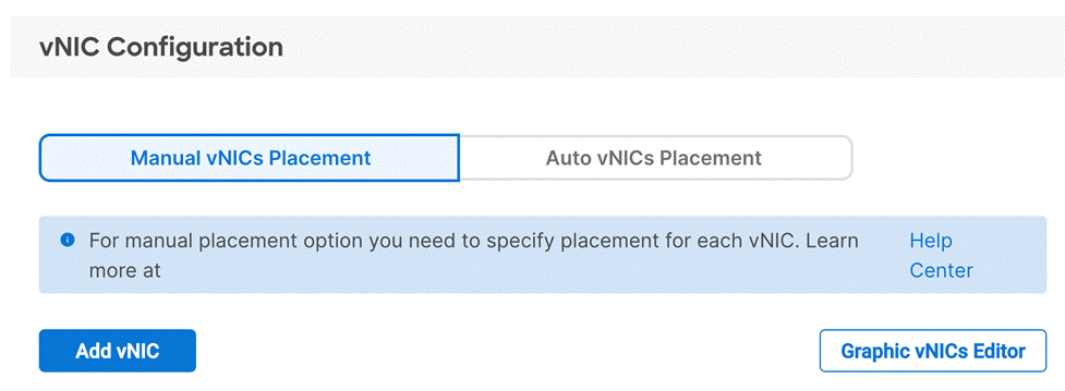
Step 3. Under vNIC Configuration, select Manual vNICs Placement.
Step 4. Click Add vNIC.
Procedure 2. Network Configuration - LAN Connectivity - Define MAC Pool for Fabric Interconnects A and B
Note: If the MAC address pool has not been defined yet, when creating the first vNIC new MAC address pools will need to be created. Two separate MAC address pools are configured: MAC-Pool-A will be used for all Fabric-A vNICs, and MAC-Pool-B will be used for all Fabric-B vNICs.
Table 7. MAC Address Pools
| Pool Name |
Starting MAC Address |
Size |
vNICs |
| MAC-Pool-A |
00:25:B5:A1:0A:00 |
256* |
00-VDS01-A, 02-VDS02-A |
| MAC-Pool-B |
00:25:B5:A1:0B:00 |
256* |
01-VDS01-B, 03-VDS02-B |
Note: Each server requires 2 MAC addresses from each pool. Adjust the size of the pool according to your requirements. “A1” in the MAC address pool above is a unique identifier representing the rack ID while 0A/0B identifies the Fabric A or Fabric B. Adding a unique identifier help with troubleshooting of switching issues.
Step 1. Click Select Pool under MAC Address Pool and then, in the pane on the right, click Create New.
Step 2. Verify correct organization is selected from the drop-down list (for example, AA01) and provide a name for the pool from Table 7 depending on the vNIC being created (for example, AA01-MAC-Pool-A for Fabric A vNICs and AA01-MAC-Pool-B for Fabric B vNICs).
Step 3. Click Next.
Step 4. Provide the starting MAC address from Table 7 (for example, 00:25:B5:A1:0A:00).
Step 5. Provide the size of the MAC address pool from Table 7 (for example, 256).
Step 6. Click Create to finish creating the MAC address pool.
Step 7. From the Add vNIC window, provide vNIC Name, Slot ID, Switch ID, and PCI Order information from Table 6.
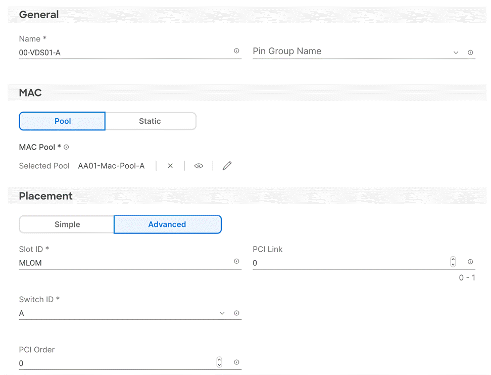
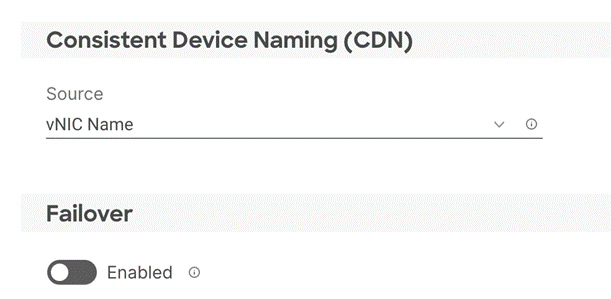
Step 8. For Consistent Device Naming (CDN), from the drop-down list, select vNIC Name.
Step 9. Verify that Failover is disabled because the failover will be provided by attaching multiple NICs to the VMware vSwitch and VDS.
Procedure 3. Network Configuration - LAN Connectivity – Define Ethernet Network Group Policy for a vNIC
Ethernet Network Group policies are created and reused on applicable vNICs as covered below. Ethernet network group policy defines the VLANs allowed for a particular vNIC therefore multiple network group policies will be defined as follows:
Table 8. Ethernet Group Policy Values
| Group Policy Name |
Native VLAN |
Apply to vNICs |
VLANs |
| Mgmt-VDS01-NetGrp |
Native-VLAN (2) |
00-VDS01-A, 01-VDS01-B |
OOB-MGMT*, IB-MGMT, vSAN, vMotion |
| Mgmt-VDS02-NetGrp |
Native-VLAN (2) |
02-VDS02-A, 03-VDS02-B |
Mgmt-Host-Overlay |
| WD-VDS01-NetGrp |
Native-VLAN (2) |
00-VDS01-A, 01-VDS01-B |
OOB-MGMT*, IB-MGMT, NFS |
| WD-VDS02-NetGrp |
Native-VLAN (2) |
02-VDS02-A, 03-VDS02-B |
WD-Host-Overlay, vMotion, VM-Traffic |
Note: * Adding Out of Band Management VLAN is optional and depends on customer networking requirements.
Step 1. Click Select Policy under Ethernet Network Group Policy and then, in the pane on the right, click Create New.
Step 2. Verify correct organization is selected from the drop-down list (for example, AA01) and provide a name for the policy from the Table 8 (for example, Mgmt-VDS01-NetGrp).
Step 3. Click Next.
Step 4. Enter the Allowed VLANs and Native VLAN from the Table 8.
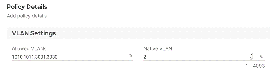
Step 5. Click Create to finish configuring the Ethernet network group policy.
Note: When ethernet group policies are shared between two vNICs, the ethernet group policy only needs to be defined for the first vNIC. For subsequent vNIC policy mapping, just click Select Policy and pick the previously defined ethernet group policy from the list.
Procedure 4. Network Configuration - LAN Connectivity – Create Ethernet Network Control Policy
Ethernet Network Control Policy is used to enable Cisco Discovery Protocol (CDP) and Link Layer Discovery Protocol (LLDP) for the vNICs. A single policy will be created here and reused for all the vNICs.
Step 1. Click Select Policy under Ethernet Network Control Policy and then, in the pane on the right, click Create New.
Step 2. Verify correct organization is selected from the drop-down list (for example, AA01) and provide a name for the policy (for example, AA01-Enable-CDP-LLDP).
Step 3. Click Next.
Step 4. Enable Cisco Discovery Protocol and both Enable Transmit and Enable Receive under LLDP.
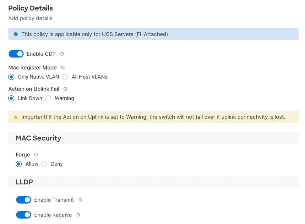
Step 5. Click Create to finish creating Ethernet network control policy.
Procedure 5. Network Configuration - LAN Connectivity – Create Ethernet QoS Policy
Ethernet QoS policy is used to enable jumbo maximum transmission units (MTUs) for the vNICs. A single policy will be created and reused for all the vNICs.
Step 1. Click Select Policy under Ethernet QoS and in the pane on the right, click Create New.
Step 2. Verify correct organization is selected from the drop-down list (for example, AA01) and provide a name for the policy (for example, AA01-EthernetQos-Pol).
Step 3. Click Next.
Step 4. Change the MTU, Bytes value to 9000.
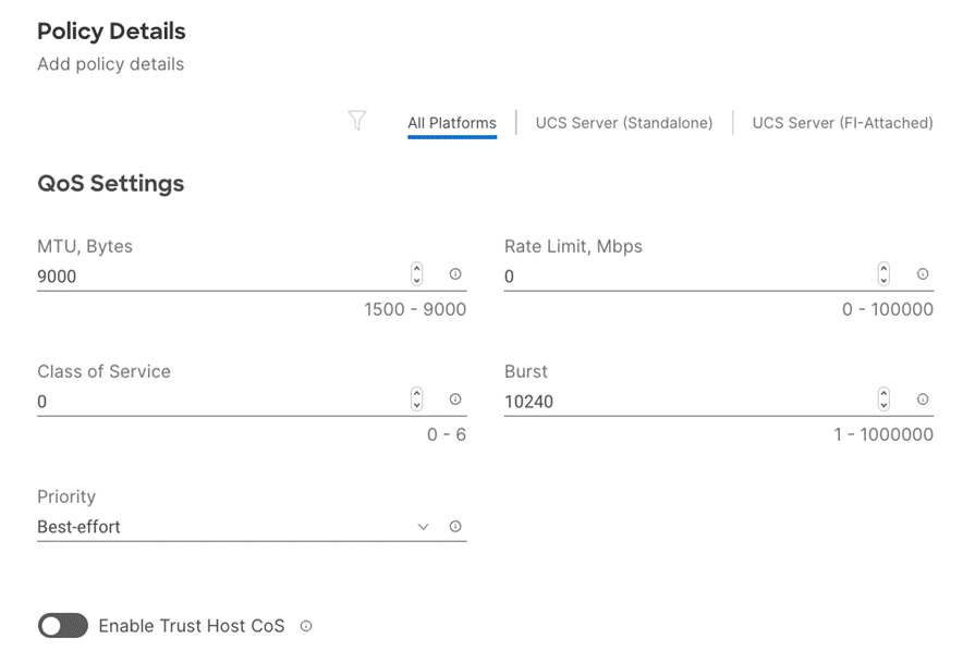
Step 5. Click Create to finish setting up the Ethernet QoS policy.
Procedure 6. Network Configuration - LAN Connectivity – Create Ethernet Adapter Policy
Ethernet adapter policy is used to set the interrupts and the send and receive queues. The values are set according to the best-practices guidance for the operating system in use. Cisco Intersight provides default VMware Ethernet Adapter policy for typical VMware deployments.
Customers can also configure a tweaked ethernet adapter policy for additional hardware receive queues handled by multiple CPUs in scenarios where there is a lot of vMotion traffic and multiple flows. In this deployment, a modified ethernet adapter policy, AA01-EthAdapter-HighTraffic-Policy, is created and attached to the 00-VDS01-A and 01-VDS01-B interfaces on management domain hosts and 02-VDS02-A and 03-VDS02-B interfaces on VI workload domain hosts which handle vMotion.
Table 9. Ethernet Adapter Policy association to vNICs
| Host Type |
Policy Name |
Apply to vNICs |
Description |
| Management Domain Host |
AA01-EthAdapter-HighTraffic-Policy |
00-VDS01-A, 01-VDS01-B |
Support vMotion |
| Management Domain Host |
AA01-EthAdapter-VMware-Policy |
02-VDS02-A, 03-VDS02-B |
Application Traffic |
| VI Workload Domain |
AA01-EthAdapter-VMware-Policy |
00-VDS01-A, 01-VDS01-B |
Management and NFS |
| VI Workload Domain |
AA01-EthAdapter-HighTraffic-Policy |
02-VDS02-A, 03-VDS02-B |
Support vMotion |
Step 1. Click Select Policy under Ethernet Adapter and then, in the pane on the right, click Create New.
Step 2. Verify correct organization is selected from the drop-down list (for example, AA01) and provide a name for the policy (for example, AA01-EthAdapter-VMware-Policy).
Step 3. Click Select Default Configuration under Ethernet Adapter Default Configuration.
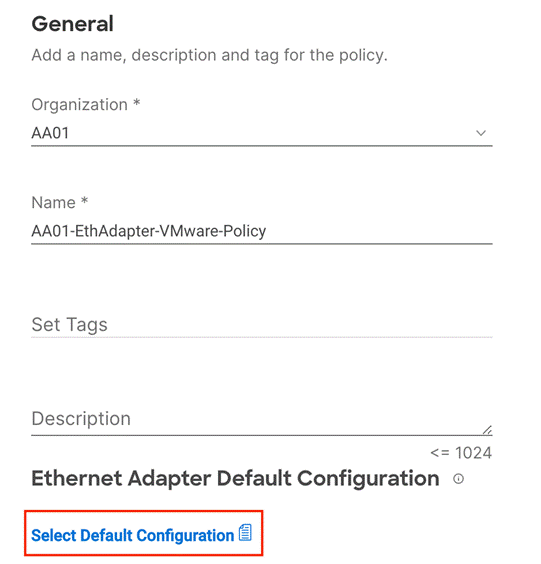
Step 4. From the list, select VMware.
Step 5. Click Next.
Step 6. For the AA01-EthAdapter-VMware policy, click Create and skip the rest of the steps in this “Create Ethernet Adapter Policy” section.
Step 7. For the AA01-VMware-High-Traffic policy, make the following modifications to the policy:
● Increase Interrupts to 11
● Increase Receive Queue Count to 8
● Increase Completion Queue Count to 9
● Enable Receive Side Scaling
● Set Receive Ring Size and Transmit Ring Size to 4096

Step 8. Click Create.
Step 9. Click Add to add the vNIC to the LAN connectivity policy.
Step 10. Go back to step 4 Add vNIC and repeat vNIC creation for all four vNICs.
Step 11. Verify all four vNICs were successfully created for appropriate LAN connectivity Policy.
Step 12. Click Create to finish creating the LAN Connectivity policy.
Procedure 7. Network Connectivity – Create SAN Connectivity Policy (only for VI workload domain)
A SAN connectivity policy determines the network storage resources and the connections between the server and the storage device on the network. This policy enables customers to configure the vHBAs that the servers use to communicate with the SAN. Table 10 lists the details of two vHBAs that are used to provide FC connectivity and boot from SAN functionality.
Note: SAN Connectivity policy is not needed for management domain hosts and can be skipped when configuring the Server Profile Template for the management hosts.
Table 10. vHBAs for FlexPod VI workload domain (boot from FC)
| vNIC/vHBA Name |
Slot |
Switch ID |
PCI Order |
| vHBA-A |
MLOM |
A |
4 |
| vHBA-B |
MLOM |
B |
5 |
Step 1. Click Select Policy next to SAN Connectivity and then, in the pane on the right, click Create New.
Step 2. Verify correct organization is selected from the drop-down list (for example, AA01) and provide a name for the policy (for example, AA01-SAN-Connectivity-Policy).
Step 3. Select Manual vHBAs Placement.
Step 4. Select Pool under WWNN Address.
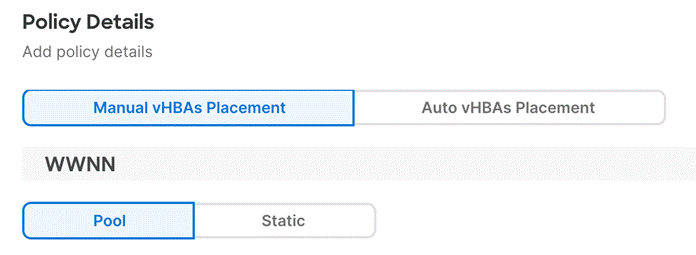
Procedure 8. Network Connectivity - SAN Connectivity – WWNN Pool
If the WWNN address pools have not been previously defined, a new WWNN address pool must be defined when adding the SAN connectivity policy.
Step 1. Click Select Pool under WWNN Address Pool and then, in the pane on the right, click Create New.
Step 2. Verify correct organization is selected from the drop-down list (for example, AA01) and provide a name for the policy (for example, AA01-WWNN-Pool).
Step 3. Click Next.
Step 4. Provide the starting WWNN block address and the size of the pool.
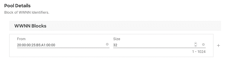
Note: As a best practice, some additional information is always encoded into the WWNN address pool for ease of troubleshooting. For example, in the address 20:00:00:25:B5:A1:00:00, A1 is the rack ID.
Step 5. Click Create to finish creating the WWNN address pool.
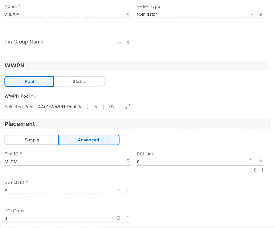
Procedure 9. Network Connectivity - SAN Connectivity – Create vHBA for SAN A
Step 1. Click Add vHBA.
Step 2. For vHBA Type, select fc-initiator from the drop-down list.
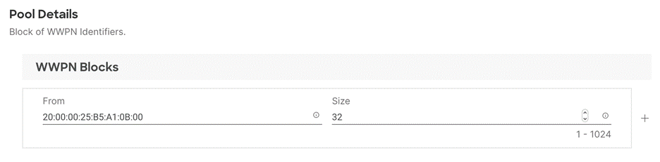
Procedure 10. Network Connectivity - SAN Connectivity – WWPN Pool for SAN A
If the WWPN address pool has not been previously defined, a new WWPN address pool for Fabric A must be defined when adding a vHBA.
Step 1. Click Select Pool under WWPN Address Pool and then, in the pane on the right, click Create New.
Step 2. Verify correct organization is selected from the drop-down list (for example, AA01) and provide a name for the policy (for example, AA01-WWPN-Pool-A).
Step 3. Provide the starting WWPN block address for SAN A and the size of the pool.
Note: As a best practice, in FlexPod some additional information is always encoded into the WWPN address pool for ease of troubleshooting. For example, in the address 20:00:00:25:B5:A1:0A:00, A1 is the rack ID and 0A signifies SAN A.
Step 4. Click Create to finish creating the WWPN pool.
Step 5. Back in the Create vHBA window, provide the Name (for example, vHBA-A), select Advanced under placement option, and add Slot ID (for example, MLOM), Switch ID (for example, A) and PCI Order from Table 10.
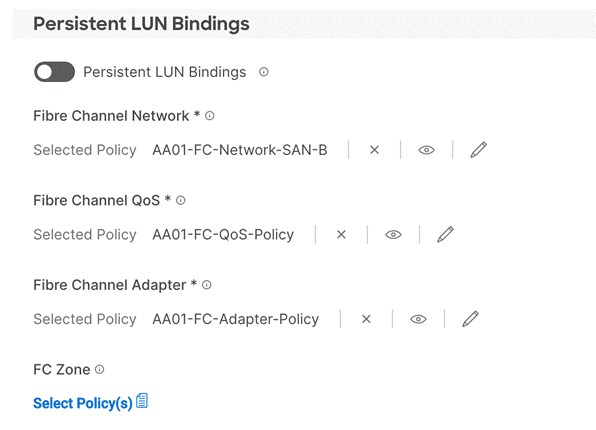
Procedure 11. Network Connectivity - SAN Connectivity - Fibre Channel Network for SAN A
A Fibre Channel network policy governs the VSAN configuration for the virtual interfaces. In this deployment, VSAN 101 is used for vHBA-A.
Step 1. Click Select Policy under Fibre Channel Network and then, in the pane on the right, click Create New.
Step 2. Verify correct organization is selected from the drop-down list (for example, AA01) and provide a name for the policy (for example, AA01-FC-Network-SAN-A).
Step 3. For the scope, make sure UCS Server (FI-Attached) is selected.
Step 4. Under VSAN ID, provide the VSAN information (for example, 101).
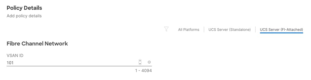
Step 5. Click Create to finish creating the Fibre Channel network policy.
Procedure 12. Network Connectivity - SAN Connectivity - Fibre Channel QoS
The Fibre Channel QoS policy assigns a system class to the outgoing traffic for a vHBA. This system class determines the quality of service for the outgoing traffic. The Fibre Channel QoS policy used in this deployment uses default values and will be shared by all vHBAs.
Step 1. Click Select Policy under Fibre Channel QoS and then, in the pane on the right, click Create New.
Step 2. Verify correct organization is selected from the drop-down list (for example, AA01) and provide a name for the policy (for example, AA01-FC-QoS-Policy).
Step 3. For the scope, select UCS Server (FI-Attached).
Step 4. Do not change the default values on the Policy Details screen.
Step 5. Click Create to finish creating the Fibre Channel QoS policy.
Procedure 13. Network Connectivity - SAN Connectivity - Fibre Channel Adapter
A Fibre Channel adapter policy governs the host-side behavior of the adapter, including the way that the adapter handles traffic. This validation uses the default values for the adapter policy, and the policy will be shared by all the vHBAs.
Step 1. Click Select Policy under Fibre Channel Adapter and then, in the pane on the right, click Create New.
Step 2. Verify correct organization is selected from the drop-down list (for example, AA01) and provide a name for the policy (for example, AA01-FC-Adapter-Policy).
Step 3. For the scope, select UCS Server (FI-Attached).
Step 4. Do not change the default values on the Policy Details screen.
Step 5. Click Create to finish creating the Fibre Channel adapter policy.
Step 6. Click Add to create vHBA-A.
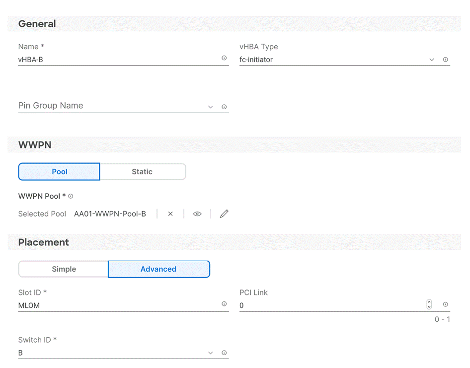
Procedure 14. Network Connectivity - SAN Connectivity – Add vHBA-B for SAN B
Step 1. Click Add vHBA.
Step 2. For vHBA Type, select fc-initiator from the drop-down list.
Procedure 15. Network Connectivity - SAN Connectivity – WWPN Pool for SAN B
If the WWPN address pool has not been previously defined, a WWPN address pool for Fabric B must be defined for vHBA-B.
Step 1. Click Select Pool under WWPN Address Pool and then, in the pane on the right, click Create New.
Step 2. Verify correct organization is selected from the drop-down list (for example, AA11) and provide a name for the policy (for example, AA01-WWPN-Pool-B).
Step 3. Provide the starting WWPN block address for SAN B and the size of the pool.
Note: As a best practice, in FlexPod some additional information is always encoded into the WWPN address pool for ease of troubleshooting. For example, in the address 20:00:00:25:B5:A1:0B:00, A1 is the rack ID and 0B signifies SAN B.
Step 4. Click Create to finish creating the WWPN pool.
Step 5. Back in the Create vHBA window, provide the Name (for example, vHBA-B), select Advanced under placement option, and add Slot ID (for example, MLOM), Switch ID (for example, B) and PCI Order from Table 10.
Procedure 16. Network Connectivity - SAN Connectivity - Fibre Channel Network for SAN B
In this deployment, VSAN 102 will be used for vHBA-B.
Step 1. Click Select Policy under Fibre Channel Network and then, in the pane on the right, click Create New.
Step 2. Verify correct organization is selected from the drop-down list (for example, AA01) and provide a name for the policy (for example, AA01-FC-Network-SAN-B).
Step 3. For the scope, select UCS Server (FI-Attached).
Step 4. Under VSAN ID, provide the VSAN information (for example, 102).
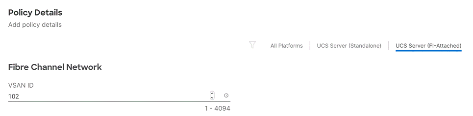
Step 5. Click Create.
Procedure 17. Network Connectivity - SAN Connectivity - Fibre Channel QoS
Step 1. Click Select Policy under Fibre Channel QoS and then, in the pane on the right, select the previously created QoS policy AA17-FC-QoS.
Procedure 18. Network Connectivity - SAN Connectivity - Fibre Channel Adapter
Step 1. Click Select Policy under Fibre Channel Adapter and then, in the pane on the right, select the previously created Adapter policy AA17-FC-Adapter.
Step 2. Verify all the vHBA policies are mapped.
Step 3. Click Add to add the vHBA-B.
Step 4. Verify both the vHBAs are added to the SAN connectivity policy.
Step 5. Click Create to finish creating SAN connectivity policy.
Step 6. When the LAN connectivity policy and SAN connectivity policy (for FC) is created, click Next to move to the Summary screen.
Procedure 1. Summary
Step 1. On the summary screen, verify policies mapped to various settings.
Step 2. Click Close to finish Server Profile Template creation.
Note: Remember to create both management domain host and VI workload domain host Server Profile Templates using the Server Profile Templates Creation procedure.
Derive Management Domain Server Profile
Procedure 1. Derive One or more Server Profiles
Step 1. From the Infrastructure Services > Configure > Templates, click “…” next to the management host template name and select Derive Profiles.
Step 2. Under the Server Assignment, select Assign Now and pick four Cisco UCS C240 M5 racks servers. Customers can adjust the number of servers depending on the number of profiles to be deployed.
Note: In this deployment four (minimum) management domain hosts will be derived. Only two out of four servers are shown in the screen capture shown below:
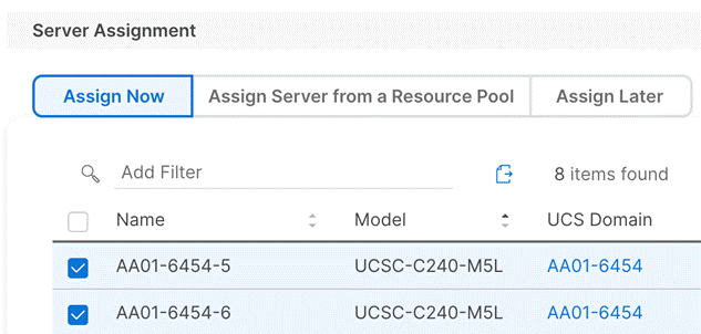
Step 3. Click Next.
Step 4. Cisco Intersight will fill in the “default” information for the selected servers (only two out of four servers shown):
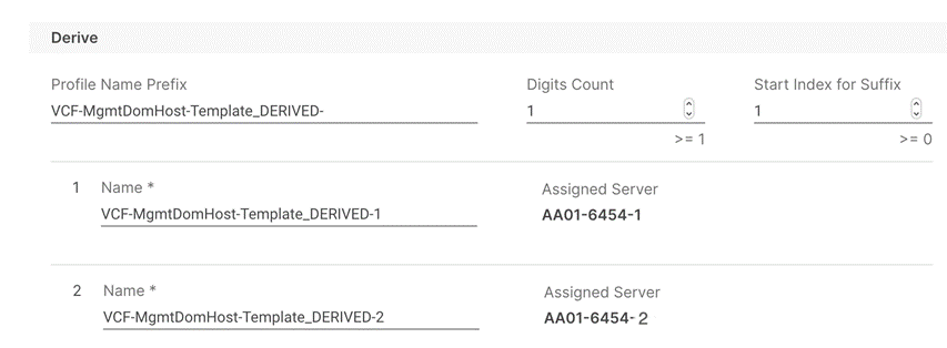
Step 5. Adjust the Prefix name and number (if needed).
Step 6. Click Next.
Step 7. Verify the information and click Derive to create the Server Profiles.
Step 8. Cisco Intersight will start configuring the server profiles and will take some time to apply all the policies. Use the Requests tab to see the progress.

Step 9. When the Server Profiles are deployed successfully, they will appear under the Server Profiles with the status of OK. Only two out of four servers are shown below:
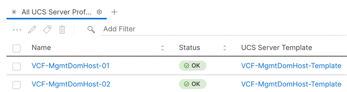
Derive VI Workload Domain Server Profile
Procedure 1. Derive One or more Server Profiles
Step 1. From the Infrastructure Services > Configure > Templates, click “…” next to the VI Workload Domain Host template name and select Derive Profiles.
Step 2. Under the Server Assignment, select Assign Now and pick three Cisco UCS X210c M6 compute nodes. Customers can adjust the number of servers depending on the number of profiles to be deployed.
Note: In this deployment three FlexPod VI Workload Domain hosts will be derived.
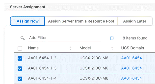
Step 3. Click Next.
Step 4. Cisco Intersight will fill in “default” information for the selected servers (only two out of three servers shown):
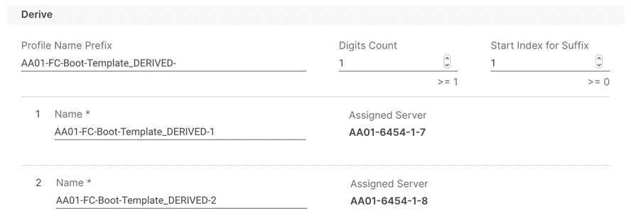
Step 5. Adjust the Prefix name and number (if needed).
Step 6. Click Next.
Step 7. Verify the information and click Derive to create the Server Profiles.
Step 8. Cisco Intersight will start configuring the server profiles and will take some time to apply all the policies. Use the Requests tab to see the progress.

Step 9. When the Server Profiles are deployed successfully, they will appear under the Server Profiles with the status of OK.
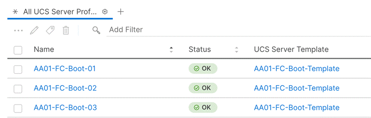
SAN Switch Configuration
This chapter contains the following:
● Initial Switch Configuration
● Add NTP Servers and Local Time Configuration
This chapter provides the procedure for configuring the Cisco MDS 9132T switches used for Fibre Channel (FC) switching in this solution. The switch configuration for this validated design is based on the MDS configuration explained in the FlexPod Datacenter with Cisco UCS X-Series Cisco Validated Design (CVD): https://www.cisco.com/c/en/us/td/docs/unified_computing/ucs/UCS_CVDs/flexpod_xseries_vmware_7u2.html#SANSwitchConfiguration, therefore, this chapter only explains the changes from the base CVD.
Follow the physical connectivity guidelines for FlexPod as explained in the Physical Topology section.
To set up the initial switch configuration, complete the steps explained here: https://www.cisco.com/c/en/us/td/docs/unified_computing/ucs/UCS_CVDs/flexpod_xseries_vmware_7u2.html#FlexPodCiscoMDSBase
Enable Features
To set up various features on Cisco MDS, complete the steps explained here: https://www.cisco.com/c/en/us/td/docs/unified_computing/ucs/UCS_CVDs/flexpod_xseries_vmware_7u2.html#EnableFeature
Add NTP Servers and Local Time Configuration
To configure the NTP server and add local time configuration, complete the steps explained here: https://www.cisco.com/c/en/us/td/docs/unified_computing/ucs/UCS_CVDs/flexpod_xseries_vmware_7u2.html#AddNTPServersandLocalTimeConfiguration
To set up the port and port-channel configuration, complete the steps explained here: https://www.cisco.com/c/en/us/td/docs/unified_computing/ucs/UCS_CVDs/flexpod_xseries_vmware_7u2.html#ConfigureIndividualPorts
Cisco MDS 9132T A
To create necessary VSANs, complete the steps explained here: https://www.cisco.com/c/en/us/td/docs/unified_computing/ucs/UCS_CVDs/flexpod_xseries_vmware_7u2.html#CreateVSANs
To obtain the WWPN information from Cisco Intersight and NetApp and to configure device aliases, complete the steps explained here: https://www.cisco.com/c/en/us/td/docs/unified_computing/ucs/UCS_CVDs/flexpod_xseries_vmware_7u2.html#CreateDeviceAliases
To configure the zones and zonesets, complete the steps explained here: https://www.cisco.com/c/en/us/td/docs/unified_computing/ucs/UCS_CVDs/flexpod_xseries_vmware_7u2.html#CreateZonesandZoneset
At this time, two Cisco MDS switches should be fully configured, and the ports and port-channels should be enabled. Zoning configuration on MDS will allow compute nodes to communicate with the NetApp Storage.
Storage Configuration – ONTAP Boot Storage Setup
This chapter contains the following:
● Create and map Initiator Groups
This configuration requires information from both the server profiles and NetApp storage system. After creating the boot LUNs, initiator groups and appropriate mappings between the two, Cisco UCS server profiles will be able to see the boot disks hosted on NetApp controllers.
To create boot LUNs for all three (or more) VI workload domain ESXi servers, complete the steps explained here: https://www.cisco.com/c/en/us/td/docs/unified_computing/ucs/UCS_CVDs/flexpod_xseries_vmware_7u2.html#CreateBootLUNs
Create and map Initiator Groups
To obtain the WWPN information from Cisco Intersight, create the initiator groups for the three (or more) VI workload domain hosts, and to map these initiator groups to the boot LUNs, complete the steps explained here: https://www.cisco.com/c/en/us/td/docs/unified_computing/ucs/UCS_CVDs/flexpod_xseries_vmware_7u2.html#CreateInitiatorGroups
Note: On completing this storage configuration, the VI workload domain hosts should be able to access their boot LUNs on NetApp storage. VMware vSphere ESXi 7.0U3 can be installed on the configured boot LUNs for all the hosts.
VMware vSphere ESXi 7.0U3 Initial Setup
This chapter contains the following:
● Download ESXi 7.0U3 from VMware
● Access Cisco Intersight and Launch KVM
● Set Up VMware ESXi Installation
This section provides detailed instructions for installing VMware ESXi 7.0 U3 on all the hosts in the environment. On successful completion of these steps, four ESXi hosts with will be available to setup the management domain and three ESXi hosts will be available for the VI workload domain. ESXi software will be installed on the local drive for the management hosts and FC based boot LUNs for the VI workload domain hosts.
Several methods exist for installing ESXi in a VMware environment. This procedure focus on using the built-in keyboard, video, mouse (KVM) console and virtual media features in Cisco Intersight to map remote installation media to individual servers.
Download ESXi 7.0U3 from VMware
Procedure 1. Download VMware ESXi ISO
Step 1. Click the following link: Cisco Custom Image for ESXi 7.0 U3 Install CD.
Step 2. Download the .iso file.
Note: You will need a VMware user id and password on vmware.com to download this software.
Access Cisco Intersight and Launch KVM
The Cisco Intersight KVM enables the administrators to begin the installation of the operating system (OS) through remote media. It is necessary to log into the Cisco Intersight to access KVM.
Procedure 1. Access Server KVM
Step 1. Log into the Cisco Intersight.
Step 2. From the main menu, select Infrastructure Service > Servers.
Step 3. Find the desired server and click “…” to see more options.
Step 4. Click Launch vKVM.
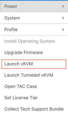
Step 5. Follow the prompts to ignore certificate warnings (if any) and launch the HTML5 KVM console.
Note: Customers can launch the HTML5 KVM console for all the servers at the same time, but lab validation seemed to work the best when working with a couple of hosts at a time.
Note: Since the Cisco Custom ISO image will be mapped to the vKVM for software installation, it is better to use the standard vKVM (not the Tunneled vKVM) and that the Cisco Intersight is being accessed from a PC that has routable (or direct) access to the management network.
Set Up VMware ESXi Installation
Procedure 1. Prepare the Server for the OS Installation on each ESXi Host
Step 1. In the KVM window, click Virtual Media > vKVM-Mapped vDVD
Step 2. Browse and select the ESXi installer ISO image file downloaded in the last step.
Step 3. Click Map Drive.
Step 4. Select Macros > Static Macros > Ctrl + Alt + Delete to reboot the Server if the server is showing shell prompt. If the server is shutdown, from Intersight, select Power > Power On System.
Step 5. Monitor the server boot process in the KVM.
● VI workload domain servers should find the FC boot LUNs and then load the ESXi installer
● Management Domain servers should load the ESXi installer.
Note: If the ESXi installer fails to load because the software certificates cannot be validated, reset the server, and when prompted, press F2 to go into BIOS and set the system time and date to current. The ESXi installer should load properly.
Procedure 1. Install VMware ESXi onto the Bootable LUN of the Cisco UCS Servers on each Host
Step 1. After the ESXi installer is finished loading (from the last step), press Enter to continue with the installation.
Step 2. Read and accept the end-user license agreement (EULA). Press F11 to accept and continue.
Note: It may be necessary to map function keys as User Defined Macros under the Macros menu in the KVM console.
Step 3. Select the M.2 local drive as installation disk for the management domain hosts or select the FC NetApp boot LUN as the installation disk for VI workload domain hosts and press Enter to continue with the installation.
Step 4. Select the appropriate keyboard layout and press Enter.
Step 5. Enter and confirm the root password and press Enter.
Step 6. The installer issues a warning that the selected disk will be repartitioned. Press F11 to continue with the installation.
Step 7. After the installation is complete, click on Virtual Media to unmap the installer ISO. Press Enter to reboot the server.
Step 8. Repeat this procedure for installing ESXi on all the servers in the environment.
All the hosts in the environment need to be configured with following base configuration before a host can be onboarded in the VMware Cloud Foundation setup:
● Setup management access and enable SSH access
● Set hostname and DNS
● Set jumbo MTU on default vSwitch
● Set management VLAN for default VM Network port-group
● Configure NTP server
● Update drivers
● Regenerate Certificates on all the ESXi hosts
Procedure 1. Set Up Management Access, enable SSH, set NTP and DNS information on each Host
Adding a management network for each VMware host is required for accessing and managing the host.
Step 1. After the server has finished rebooting, in the KVM console, press F2 to customize VMware ESXi.
Step 2. Log in as root, enter the password set during installation, and press Enter to log in.
Step 3. Use the down arrow key to select Troubleshooting Options and press Enter.
Step 4. Select Enable SSH and press Enter.
Step 5. Press Esc to exit the Troubleshooting Options menu.
Step 6. Select the Configure Management Network option and press Enter.
Step 7. Select Network Adapters and press Enter.
Step 8. Verify vmnic0 is selected as the only device.
Note: Do not add the second redundant NIC at this time.
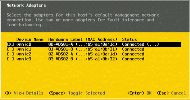
Step 9. Press Enter.
Step 10. Under VLAN (optional) enter the IB-MGMT VLAN (for example, 1011) and press Enter.
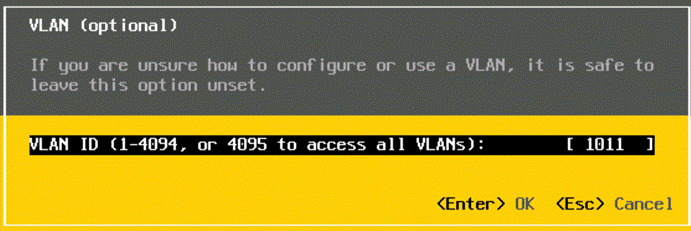
Step 11. Select IPv4 Configuration and press Enter.
Note: When using DHCP to set the ESXi host networking configuration, setting up a manual IP address is not required.
Step 12. Select the Set static IPv4 address and network configuration option by using the arrow keys and space bar.
Step 13. Under IPv4 Address, enter the IP address for managing the ESXi host.
Step 14. Under Subnet Mask, enter the subnet mask.
Step 15. Under Default Gateway, enter the default gateway.
Step 16. Press Enter to accept the changes to the IP configuration.
Step 17. Select the IPv6 Configuration option and press Enter.
Step 18. Using the spacebar, select Disable IPv6 (restart required) and press Enter.
Step 19. Select the DNS Configuration option and press Enter.
Note: If the IP address is configured manually, the DNS information must be provided. Make sure the ESXi hostnames are populated in the DNS server because VMware Cloud Foundation requires DNS resolution (both forward and reverse lookups) of all the ESXi hosts and the VCF component VMs.
Step 20. Using the spacebar, select Use the following DNS server addresses and hostname:
Step 21. Under Primary DNS Server, enter the IP address of the primary DNS server.
Step 22. Optional: Under Alternate DNS Server, enter the IP address of the secondary DNS server.
Step 23. Under Hostname, enter the fully qualified domain name (FQDN) for the ESXi host.
Step 24. Press Enter to accept the changes to the DNS configuration.
Step 25. Press Esc to exit the Configure Management Network submenu.
Step 26. Press Y to confirm the changes and reboot the ESXi host.
Procedure 2. (Optional) Reset VMware ESXi Host VMkernel Port MAC Address
By default, the MAC address of the management VMkernel port vmk0 is the same as the MAC address of the Ethernet port it is placed on. If the ESXi host’s boot LUN is remapped to a different server with different MAC addresses, a MAC address conflict will exist because vmk0 will retain the assigned MAC address unless the ESXi System Configuration is reset. Reset the MAC address of vmk0 to a random VMware-assigned MAC address.
Step 1. From the ESXi console menu main screen, type Ctrl-Alt-F1 to access the VMware console command line interface. In the Cisco Intersight KVM, Ctrl-Alt-F1 appears in the list of Static Macros.
Step 2. Log in as root.
Step 3. Type “esxcfg-vmknic –l” to get a detailed listing of interface vmk0. vmk0 should be a part of the “Management Network” port group. Note the IP address and netmask of vmk0.
Step 4. To remove vmk0, type esxcfg-vmknic –d “Management Network”.
Step 5. To re-add vmk0 with a random MAC address, type esxcfg-vmknic –a –i <vmk0-ip> -n <vmk0-netmask> “Management Network”.
Step 6. Verify vmk0 has been re-added with a random MAC address by typing esxcfg-vmknic –l.
Step 7. Tag vmk0 as the management interface by typing esxcli network ip interface tag add -i vmk0 -t Management.
Step 8. When vmk0 was re-added, if a message pops up saying vmk1 was marked as the management interface, type esxcli network ip interface tag remove -i vmk1 -t Management.
Step 9. Verify vmk1 has been re-added with a random MAC address by typing esxcfg-vmknic –l.
Step 10. Exit the ESXi host configuration:
Step 11. Type exit to log out of the command line interface.
Step 12. Type Ctrl-Alt-F2 to return to the ESXi console menu interface.
Procedure 3. Setup Jumbo MTU on vSwitch and management VLAN on VM Network port-group
In this procedure, log into each ESXi host using a web browser and set the following options.
Step 1. Open a web browser and navigate to the first ESXi server’s management IP address.
Step 2. Enter “root” as the username.
Step 3. Enter the <root password>.
Step 4. Click Log in to connect.
Step 5. Decide whether to join the VMware Customer Experience Improvement Program or not and click OK.
Step 6. From the Host Client Navigator, select Networking.
Step 7. In the center pane, select the Virtual switches tab.
Step 8. Click vSwitch0.
Step 9. Click Edit settings.
Step 10. Change the MTU to 9000.
Step 11. Click Save.
Step 12. Select Networking, then select the Port groups tab.
Step 13. In the center pane, right-click VM Network and select Edit settings.
Step 14. Set the VLAN ID to <IB-MGMT-VLAN> (for example, 1011).
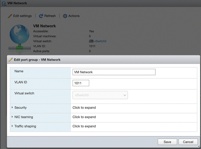
Step 15. Click Save to finalize the edits for the VM Network port group.
Procedure 4. Configure NTP Server on the ESXi Hosts
Step 1. From the left pane in the ESXi web console, click Manage under Host.
Step 2. In the center pane, select System > Time & date.
Step 3. Click Edit NTP Settings.
Step 4. Select Use Network Time Protocol (enable NTP client).
Step 5. Use the drop-down list to select Start and stop with host.
Step 6. Enter the NTP server IP address(es) in the NTP servers.
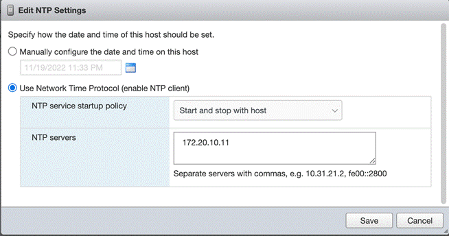
Step 7. Click Save to save the configuration changes.
Step 8. Select the Services tab.
Step 9. Right-click ntpd and select Start.
Step 10. Under System > Time & date, the NTP service status should now show “Running.”
Note: You might have to click Refresh to get the latest service status.
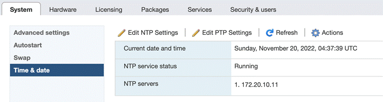
Procedure 5. Download Cisco VIC drivers and NetApp NFS Plug-in for VAAI on VI workload domain hosts
Cisco custom ISOs used to install ESXi on compute nodes contains latest supported ethernet/enic driver 1.0.42.0 and fibre-channel/fnic driver 4.0.0.87. Download the following drivers (where applicable) on FlexPod VI workload domain hosts.
Step 1. Download the NetApp NFS plugin:
● NetApp NFS Plug-in for VMware VAAI 2.0 – NetAppNasPluginV2.0.zip
Optional: If customers plan to deploy NVMe-over-FC on their hosts as secondary storage post VMware Cloud Foundation deployment, download and extract the following drivers to the Management Workstation:
● VMware ESXi 7.0 nfnic 5.0.0.34 Driver for Cisco VIC Adapters – Cisco-nfnic_5.0.0.34-1OEM.700.1.0.15843807_19966277.zip – extracted from the downloaded zip.
Optional: If compute nodes are equipped with LSI raid adapter, download the latest driver for the controller:
● VMware ESXi 7.0 lsi_mr3 7.720.04.00-1OEM SAS Driver for Broadcom Megaraid 12Gbps - Broadcom-lsi-mr3_7.720.04.00-1OEM.700.1.0.15843807_19476191.zip – extracted from the downloaded zip
Note: Consult the Cisco UCS Hardware Compatibility List and the NetApp Interoperability Matrix Tool to determine latest supported combinations of firmware and software.
Procedure 6. Install Cisco VIC drivers and NetApp NFS Plug-in for VAAI on VI workload domain hosts
Step 1. Using an SCP program, copy the bundles referenced above to the /tmp directory on each ESXi host.
Step 2. SSH to each VMware ESXi host and log in as root.
Step 3. Run the following commands on each host:
esxcli software component apply -d /tmp/Cisco-nfnic_5.0.0.34-1OEM.700.1.0.15843807_19966277.zip
esxcli software component apply -d /tmp/Broadcom-lsi-mr3_7.720.04.00-1OEM.700.1.0.15843807_19476191.zip
esxcli software vib install -d /tmp/NetAppNasPluginV2.0.zip
esxcfg-advcfg -s 0 /Misc/HppManageDegradedPaths
reboot
Step 4. After reboot, SSH back into each host and use the following commands to ensure the correct version are installed:
esxcli software component list | grep nfnic
esxcli software component list | grep lsi-mr3
esxcli software vib list | grep NetApp
esxcfg-advcfg -g /Misc/HppManageDegradedPaths
Procedure 7. Regenerate the ESXi self-signed certificates
After updating the ESXi host with the FQDN and setting up various parameters previously explained, regenerate the self-signed certificates:
Step 1. SSH to each VMware ESXi host and log in as root.
Step 2. Run the following commands on each host:
/sbin/generate-certificates
/etc/init.d/hostd restart && /etc/init.d/vpxa restart
Note: If you were logged into the web UI for any of the ESXi hosts, the session will have to be refreshed and you will need to log back in.
VMware Cloud Foundation Deployment
This chapter contains the following:
● Prepare the Existing Infrastructure
● Deploy Cloud Builder Virtual Appliance
● Deploy the Management Domain
● Commission Workload Domain Hosts
● Deploy the VI Workload Domain
VMware Cloud Foundation deployment is divided into following steps:
● Prepare the existing infrastructure
● Deploy the Cloud Builder Virtual Appliance
● Deploy the management domain*
● Onboard FlexPod workload domain ESXi hosts
● Deploy the VI workload domain
Note: *For customers who only need to onboard FlexPod VI workload domain in an existing VMware Cloud Foundation setup, the management domain setup and related infrastructure preparation steps can be skipped. This deployment guide assumes customers are setting up a new VMware Cloud Foundation from the beginning.
Prepare the Existing Infrastructure
Before starting the automated deployment of the management domain using VMware Cloud Builder, the environment must meet target prerequisites and be in a specific starting state. Make sure following elements are present in the current environment:
● The deployment environment should contain an NTP server for the ESXi hosts.
● The deployment environment should have a DNS infrastructure and all following VM hostnames should be programmed in the DNS server (both forward and reverse lookups):
◦ VMware Cloud Builder VM
◦ VMware SDDC Manager
◦ VMware vCenter for management and VI domains
◦ VMware NSX-T manager VMs and cluster VIPs for management and VI domains
◦ All the ESXi hosts for management and VI domains
● The cloud builder VM is deployed in the existing customer environment. Customers should have a vSphere environment available to deploy the cloud builder OVF.
● The management network where the VCF components are being deployed should be routable.
Table 11 lists the DNS information used during this deployment. Customers should validate both the forward and reverse lookups to verify DNS is working properly.
Table 11. VMware Cloud Foundation sample DNS information
| FQDN |
IP Address |
Description |
| aa01-ad1.vcf.local |
10.101.1.53 |
DNS server #1 |
| aa01-ad2.vcf.local |
10.101.1.54 |
DNS server #2 |
| aa01-cloudbuilder.vcf.local |
10.101.1.5 |
Cloud Builder VM |
| Management Domain |
||
| vcf-sddc |
10.101.1.110 |
SDDC manager |
| vcf-vc.vcf.local |
10.101.1.80 |
Management Domain vCenter |
| vcf-esxi-01.vcf.local |
10.101.1.81 |
Management Domain ESXi server #1 |
| vcf-esxi-02.vcf.local |
10.101.1.82 |
Management Domain ESXi server #2 |
| vcf-esxi-03.vcf.local |
10.101.1.83 |
Management Domain ESXi server #3 |
| vcf-esxi-04.vcf.local |
10.101.1.84 |
Management Domain ESXi server #4 |
| vcf-mgmt-nsx.vcf.local |
10.101.1.90 |
Management Domain NSX-T Cluster VIP |
| vcf-mgmt-nsx-1.vcf.local |
10.101.1.91 |
Management NSX-T virtual appliance node # 1 |
| vcf-mgmt-nsx-2.vcf.local |
10.101.1.92 |
Management NSX-T virtual appliance node # 2 |
| vcf-mgmt-nsx-3.vcf.local |
10.101.1.93 |
Management NSX-T virtual appliance node # 3 |
| Workload Domain |
||
| aa01-vc.vcf.local |
10.101.1.100 |
VI workload domain vCenter |
| aa01-esxi-01.vcf.local |
10.101.1.101 |
VI workload domain ESXi server #1 |
| aa01-esxi-02.vcf.local |
10.101.1.102 |
VI workload domain ESXi server #2 |
| aa01-esxi-03.vcf.local |
10.101.1.103 |
VI workload domain ESXi server #3 |
| vcf-wd-nsx.vcf.local |
10.101.1.95 |
Workload Domain NSX-T Cluster VIP |
| vcf-wd-nsx-1.vcf.local |
10.101.1.96 |
Workload Domain NSX-T virtual appliance node # 1 |
| vcf-wd-nsx-2.vcf.local |
10.101.1.97 |
Workload Domain NSX-T virtual appliance node # 2 |
| vcf-wd-nsx-3.vcf.local |
10.101.1.99 |
Workload Domain NSX-T virtual appliance node # 3 |
Deploy Cloud Builder Virtual Appliance
Cloud builder virtual appliance 4.4.1 and the associated parameter files can be downloaded from VMware website: https://customerconnect.vmware.com/en/downloads/details?downloadGroup=VCF441&productId=1252&rPId=88408
Download both VMware Cloud Builder OVA and the Cloud Builder Deployment Parameter Guide xlsx.
Procedure 1. Deploy the Cloud Builder OVA
Cloud builder OVA will be deployed on an existing VMware infrastructure.
Step 1. Log into an existing VMware vCenter and select the cluster/host where Cloud Builder OVA will be deployed.
Step 2. Right-click the cluster or host and select Deploy OVF Template.
Step 3. Select Local file and click UPLOAD FILES.
Step 4. Select the VMware Cloud Builder OVA file downloaded in the last step and click Open.
Step 5. Click NEXT.
Step 6. Provide a VM name (for example, aa01-cloudbuilder) and select the location for the install. Click NEXT.
Step 7. Verify the template details and click NEXT.
Step 8. Accept the license agreement and click NEXT.
Step 9. Select the datastore where the VM is deployed and click NEXT.
Step 10. Select the correct management network from the drop-down list and click NEXT.
Step 11. On the Customize template screen, enter password for the default admin account.
Step 12. On the same Customize template screen, enter password for the default root account.
Step 13. Scroll down and provide the Hostname, IP address, Subnet Mask, Default GW, DNS Servers, DNS Domain Name for the cloud builder appliance.
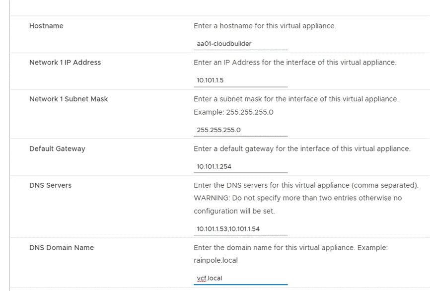
Step 14. Scroll down, provide the DNS Domain Search Paths and NTP Server. Click NEXT.
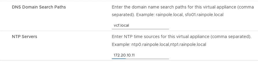
Step 15. Verify all the information and click FINISH to deploy the appliance.
Step 16. When the deployment is complete, access the Cloud Builder appliance by typing the FQDN of cloud builder (for example, https://aa01-cloudbuilder.vcf.loca) in a web browser window to verify the installation was successful.
The cloud builder appliance is now ready to deploy VMware Cloud Foundation management domain. The next step is to populate the Cloud Builder Deployment Parameter Guide with the necessary infrastructure information.
The first step in deploying VMware Cloud Foundation management domain is to fill in all the deployment information in the Cloud Builder Deployment Parameter Guide. The second step is to upload this parameters file into cloud builder and start the VMware Cloud Foundation deployment process.
Procedure 1. Update Cloud Builder Deployment Parameter Guide
Step 1. Open the Cloud Builder Deployment Parameter workbook in Microsoft Excel.
Step 2. The Introduction worksheet provides and overview of the workbook.
Step 3. Click to select Credentials worksheet.
Step 4. Add root password for all the ESXi hosts. This password was set at the time of ESXi installation.
Step 5. Provide the default passwords (to be set) for various roles of vCenter, NSX-T and SDDC Manager.
Step 6. Click to select Hosts and Networks worksheet.
Step 7. Provide the Management Network, vMotion Network and vSAN Network information including port-group name, IP subnet, IP gateway and MTU under Management Domain Networks.
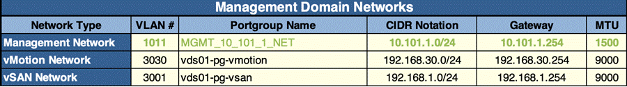
Step 8. Provide the existing vSwitch name on the ESXi hosts under Virtual Networking.
Step 9. Select Profile-3 under VDS Switch Profile
Step 10. Provide the names (to be set) for the two VDSs (for example, vds01 and vds02) and the vNICs assigned to these VDSs (for example, vmnic0, vmnic1 for vds01 and vmnic2, vmnic3 for vds02).
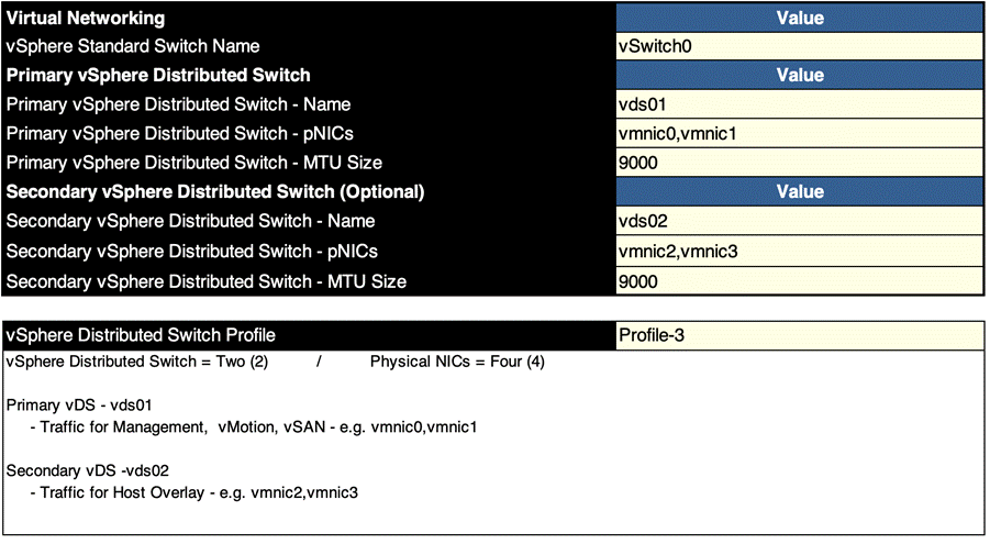
Step 11. Provide the name and IP addresses for accessing the four ESXi hosts under Management Domain ESXi Hosts.
Note: Cloud Builder appliance should be able to resolve the ESXi hostname to IP address.
Step 12. Provide the pool range (start and end IP addresses) for both vMotion and vSAN networks. An IP address from each of these ranges will be configured on every ESXi hosts.
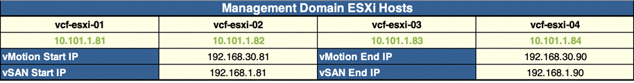
Step 13. Select No for Validate Thumbprints.
Step 14. Under the NSX-T Host Overlay Network, provide the Overlay Network VLAN ID (for example, 3002).
Step 15. Select Yes for Configure NSX-T Host Overlay Using a Static IP Pool.
Step 16. Provide the NSX-T host overlay network values including pool name, IP subnet, IP gateway and IP range.
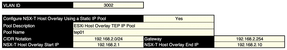
Step 17. Click to select Deploy Parameters worksheet.
Step 18. Provide the DNS and NTP server information under Existing Infrastructure Details
Step 19. Provide the DNS domain name. Select the appropriate values for participating in Customer Experience Improvement Program and enabling FIPS for SDDC Manager.
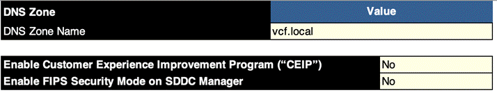
Step 20. Provide the License Keys for various VMware components.
Step 21. Provide the vCenter details including deployment size, IP address, Datacenter and Cluster name. Select Standard for VCF Architecture to be deployed.
Step 22. Provide the information about NSX-T Cluster VIP and NSX-T virtual appliances under NSX-T Data Center.
Step 23. Provide the SDDC Manager details including the management domain name to be configured.
Step 24. Save the parameters file. This file will be used to deploy VMware Cloud Foundation management domain in the next step.
Procedure 2. Deploy the VMware Cloud Foundation management domain
Step 1. Access the Cloud Builder appliance by typing the FQDN of cloud builder (for example, https://aa01-cloudbuilder.vcf.loca) in a web browser window.
Step 2. Use admin as username and password provided during the OVA deployment to log into the cloud builder appliance.
Step 3. Read and agree to the End User License Agreement and click NEXT.
Step 4. Select VMware Cloud Foundation under the select platform and click NEXT.
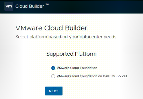
Step 5. Review the prerequisites for the SDDC deployment and agree to meeting the requirements. Click NEXT.
Step 6. Click NEXT for Download Deployment Parameter Workbook.
Step 7. Click NEXT. Deployment parameter workbook was already downloaded and filled.
Step 8. Click SELECT FILE and browse to the location of completed excel workbook and select the completed file. When the file is uploaded successfully, click NEXT.
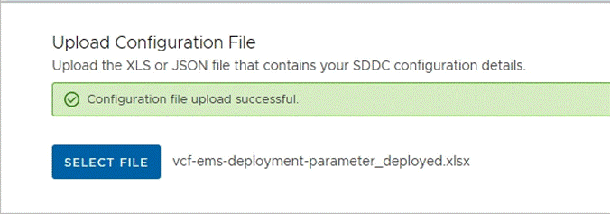
Step 9. Cloud Builder appliance will take a while and verify the uploaded file. If there are any errors, fix the errors and click RETRY.
Step 10. On successful validation of the configuration file, click NEXT.
Step 11. In the dialog box for deploying SDDC, click DEPLOY SDDC.
Step 12. Cloud Builder appliance will take a while to deploy vCenter, vSAN, SDDC-Manager, NSX-T appliances and adjusting various parameters on the ESXi hosts.
Note: You can log into the management ESXi hosts to see vCenter, vSAN and NSX-T VMs getting deployed.

Step 13. When all the configuration steps are successfully completed, Cloud Builder appliance will notify user of the deployment completed successfully. Click FINISH.
Step 14. In the pop up, click LAUNCH SDDC MANAGER.
Step 15. Use administrator@vsphere.local username and password set in the parameters workbook to log into the SDDC manager.
Step 16. Provide an input to Customer Experience Improvement Program question and click APPLY.
Now the SDDC Manager dashboard is accessible.
Step 17. Navigate to Administration > Repository Settings.
Step 18. Click on AUTHENTICATE to authorize the VMware account to access updates for VMware Cloud Foundation components.
Step 19. Provide the VMware credentials and click AUTHORIZE.
At this time, VMware Cloud Foundation management domain setup is complete. Figure 9 shows various virtual machines and their deployment configuration in the management domain. Depending on the size of the deployment chosen in the deployment worksheet, the virtual machine size could be different.
Customers can log into the VMware SDDC manager and find various deployment parameters, perform lifecycle management, and gather information about the vCenter and NSX manager. Customers may choose to perform the necessary lifecycle management for VMware Cloud Foundation by downloading and upgrading the software packages.
For more details on deployment of the management cluster using VMware cloud builder appliance, see: https://docs.vmware.com/en/VMware-Cloud-Foundation/4.4/vcf-deploy/GUID-78EEF782-CF21-4228-97E0-37B8D2165B81.html
The next step is to proceed with adding FlexPod hosts as VI workload domain.
Commission Workload Domain Hosts
VMware Cloud Foundation VI workload domain is deployed using VMware SDDC manager. When deploying a VI workload domain, the storage type, compute, and networking details are provided to the SDDC manager. Based on the selected storage, NFS share details are also provided at the time of deployment. This storage becomes the primary storage for the VI workload domain., The FlexPod VI workload domain ESXi hosts are commissioned in the SDDC manager before proceeding with the workload domain deployment. This section explains the ESXi host commissioning in SDDC manager.
Procedure 1. Create the Network Pool for NFS and vMotion IP addresses
In this procedure, a network pool will be created to assign IP addresses to NFS and vMotion VMkernel ports of the workload domain ESXi hosts.
Step 1. Log into VMware SDDC manager GUI.
Step 2. Navigate to Administration > Network Settings.
Step 3. Click on CREATE NETWORK POOL.
Step 4. Provide a Network Pool Name.
Step 5. Check NFS and vMotion.
Step 6. Provide various Network values including VLAN, MTU, IP Subnet, Subnet Mask, Default Gateway, and a range of IP addresses that will be assigned to the workload domain hosts.
Step 7. Click ADD to add both the IP address ranges.
Step 8. Click SAVE to create the network pool.
Procedure 2. Commission VI workload domain NFS hosts
In this procedure, the VI workload domain ESXi hosts will be commissioned in SDDC manager.
Step 1. Log into VMware SDDC manager GUI.
Step 2. Navigate to Inventory > Hosts.
Step 3. Click on COMMISSION HOSTS in the main panel.
Step 4. Read and verify the checklist, check Select All, and click PROCEED.
Step 5. On the Host Addition and Validation screen, select Add new.
Step 6. Provide the ESXi host FQDN (for example, aa01-esxi-01.vcf.local).
Step 7. For Storage Type, select NFS.
Step 8. From the Network Pool Name drop down, select the Network Pool create in the last procedure (for example, AA01-NP).
Step 9. For the ESXi host username, enter root.
Step 10. Provide the root password.
Step 11. Click ADD.
Step 12. Repeat steps 6 through 11 to add all three hosts.
Step 13. In the Host Added section, select all hosts, and click Confirm FingerPrint.
Step 14. Click VALIDATE ALL.
Step 15. SDDC manager will take a while and validate host configurations. When the validation is successful, Host Validated Successfully message appears on the screen.
Step 16. Click NEXT.
Step 17. Verify the information on Review screen and click COMMISSION.
Step 18. SDDC Manager will take some time to commission the hosts.
Step 19. On successful commissioning of the hosts, the hosts will appear under Inventory > Hosts in Active but Unassigned state.
These three newly commissioned hosts will be used to deploy the VI workload domain in the next step.
As part of VI workload onboarding, the VMware SDDC manager automatically:
● Deploys a vCenter Server Appliance for the new VI workload domain within the management domain.
● Connects the specified ESXi servers to this vCenter Server instance and groups them into a cluster. Each host is configured with the port groups applicable to the VI workload domain.
● Configures networking on each host.
● Configures NFS storage on the ESXi hosts.
Note: By default, VI workload domains do not include any NSX Edge clusters and are isolated. To provide north-south routing and network services, utilize the traditional VLAN based application deployment or add one or more NSX Edge clusters to a VI workload domain.
VMware SDDC manager allows customers to create a new workload domain using the SDDC Manager web graphical user interface (GUI) or by creating a description file using JSON and using VMware Cloud Foundation API. The VI workload domain deployment using GUI is simpler however the GUI only supports creation of a single VDS in the ESXi host. The FlexPod ESXi hosts contain at least four vNICs and require creation of 2 VDSs so traffic can be segregated and controlled on the vNIC basis. Figure 10 shows the ESXi host design including two VDS switches, vNICs assigned to each VDS, and port-groups and vmk ports created on each VDS.
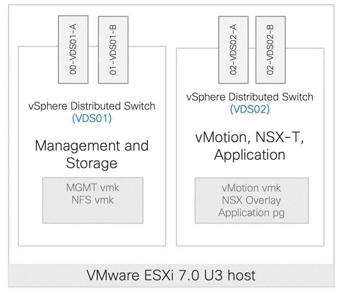
This multi-VDS configuration is completed using VMWare Cloud Foundation API. A JSON file is created with appropriate network parameters and definitions and pushed to VMware Cloud Foundation API. Using these parameters, VMWare Cloud Foundation deploys two VDSs in the VI workload domain.
Procedure 1. VI Workload Domain JSON file
In this procedure, a VI workload domain JSON description file is created. This file contains all the information necessary to deploy FlexPod VI workload domain.
Step 1. Copy the JSON file from Appendix A and edit the file in a text editor.
Step 2. Under the vcenterSpec section, provide following information:
● Name of workload domain (to be configured on SDDC manager)
● vCenter IP address
● vCenter FQDN
● vCenter IP gateway
● vCenter Subnet Mask
● vCenter root password
● vCenter datacenter name
● Size of VCenter deployment.
{
“domainName”: “AA01-WD”,
“vcenterSpec”: {
“name”: “aa01-vc”,
“networkDetailsSpec”: {
“ipAddress”: “10.101.1.100”,
“dnsName”: “aa01-vc.vcf.local”,
“gateway”: “10.101.1.254”,
“subnetMask”: “255.255.255.0”
},
“rootPassword”: “<####>”,
“datacenterName”: “AA01-WD-DC”,
“vmSize”: “small”
},
Step 3. Obtain the ESXi host ID (‘id’) for all the workload domain servers from the SDDC manager.
Step 4. Log into the SDDC manager and navigate to Developer Center > API Explorer.
Step 5. Click on APIs for managing Hosts.
Step 6. Click GET /v1/hosts.
Step 7. In status field, add UNASSIGNED_USEABLE.
Step 8. Scroll down and click EXECUTE.
Step 9. Click the response PageOfHost.
Step 10. Note the Host IDs and use these host IDs in the JSON file below.
Note: Expand each host id by clicking it to see which host the ID belongs to.
Step 11. Back in the JSON file editing, under the ComputeSpec section, provide following information for all workload domain ESXi hosts:
● Name of vCenter cluster
● Host ID (to be obtained from the SDDC manager)
● ESXi license key (must be present in SDDC Manager)
● VDS Switch name and the vNIC assignment
“computeSpec”: {
“clusterSpecs”: [
{
“name”: “AA01-WD-Cluster”,
“hostSpecs”: [
{
“id”: “<####>”,
“licenseKey”: “<####>”,
“hostNetworkSpec”: {
“vmNics”: [
{
“id”: “vmnic0”,
“vdsName”: “vds01”
},
{
“id”: “vmnic1”,
“vdsName”: “vds01”
},
{
“id”: “vmnic2”,
“vdsName”: “vds02”
},
{
“id”: “vmnic3”,
“vdsName”: “vds02”
}
]
}
},
Step 12. Under datastoreSpec section, provide the NFS LIF IP address and NFS mount path information from NetApp.
Step 13. To obtain the correct NFS LIF, find the aggregate where NFS volume is deployed. In the example below, the NFS volume is assigned to aggregate belonging to A400 Node 1. The direct NFS LIF will therefore be the LIF of Node-1 (10.101.7.1)
A400::> volume show -vserver Infra-SVM -volume infra_datastore_1 -fields Aggregate
vserver volume aggregate
-------- ---------------------- -----------------------
Infra-SVM infra_datastore_1 A400_01_NVME_SSD_1
A400::> network interface show -vserver Infra-SVM -data-protocol nfs
Logical Status Network Current Current Is
Vserver Interface Admin/Oper Address/Mask Node Port Home
----------- ---------- ---------- ------------------ ------------- ------- ----
Infra-SVM
nfs-lif01
up/up 10.101.7.1/24 A400-01 a0a-1017
true
nfs-lif02
up/up 10.101.7.2/24 A400-02 a0a-1017
true
2 entries were displayed.
Step 14. To obtain the mount path, use the following command:
A400::> volume show -vserver Infra-SVM -volume infra_datastore_1 -fields junction-path
vserver volume junction-path
-------- ---------------------- -----------------------
Infra-SVM infra_datastore_1 /infra_datastore_1
Step 15. Enter the values in the JSON file:
“datastoreSpec”: {
“nfsDatastoreSpecs”: [
{
“nasVolume”: {
“serverName”: [
“10.101.7.1”
],
“path”: “/infra_datastore_1”,
“readOnly”: false
},
“datastoreName”: “infra_datastore_1”
}
]
},
Step 16. Under networkSpec, provide the name of two VDS switches (vds01 and vds02) and port-groups associated with each VDS. VDS switch vds01 is used for management and NFS traffic while VDS switch vds02 is used for NSX-T host overlay and vMotion traffic.
“networkSpec”: {
“vdsSpecs”: [
{
“name”: “vds01”,
“portGroupSpecs”: [
{
“name”: “vds01-pg-management”,
“transportType”: “MANAGEMENT”
},
{
“name”: “vds01-pg-nfs”,
“transportType”: “NFS”
}
]
},
{
“name”: “vds02”,
“isUsedByNsxt”: true,
“portGroupSpecs”: [
{
“name”: “vds02-pg-vmotion”,
“transportType”: “VMOTION”
}
]
}
],
Step 17. Under nsxClusterSpec, provide the following information:
● Host Overlay VLAN (3003)
● IP address pool name (tep-pool)
● IP address pool range including IP subnet and IP gateway
“nsxClusterSpec”: {
“nsxTClusterSpec”: {
“geneveVlanId”: 3003,
“ipAddressPoolSpec”: {
“name”: “tep-pool”,
“subnets”: [
{
“ipAddressPoolRanges”: [
{
“start”: “192.168.3.101”,
“end”: “192.168.3.110”
}
],
“cidr”: “192.168.3.0/24”,
“gateway”: “192.168.3.254”
}
]
}
}
}
}
}
]
},
Step 18. Under nsxTSpec, provide the following information for all three NSX-T appliances:
● Name of the appliance (VM name)
● IP address
● FQDN
● IP gateway
● Subnet Mask
“nsxTSpec”: {
“nsxManagerSpecs”: [
{
“name”: “vcf-wd-nsx-1”,
“networkDetailsSpec”: {
“ipAddress”: “10.101.1.96”,
“dnsName”: “vcf-wd-nsx-1.vcf.local”,
“gateway”: “10.101.1.254”,
“subnetMask”: “255.255.255.0”
}
},
Step 19. Also, under the nsxTSpec, provide the following additional information:
● NSX-T VIP
● FQDN for NSX-T VIP
● NSX-T License Key
● Admin password for NSX manager
● NSX-T deployment size
“vip”: “10.101.1.95”,
“vipFqdn”: “vcf-wd-nsx.vcf.local”,
“licenseKey”: “<####>”,
“nsxManagerAdminPassword”: “<####>
“formFactor”: “medium”
}
}
When the JSON file is updated and saved, move to the next procedure to start workload domain deployment.
Procedure 2. VI Workload Domain Creation using VMware Cloud Foundation API
In this procedure, using the VMware Cloud Foundation API and the JSON file created in the last step, VI workload domain will be deployed.
Step 1. Log into the SDDC manager and navigate to Developer Center > API Explorer.
Step 2. Click on APIs for managing Domains.
Step 3. Click POST /v1/domains/validations.
Step 4. Copy and paste the JSON file in the domainCreationSpec box.
Step 5. Click EXECUTE to validate the specification file.
Step 6. Click CONTINUE to proceed with validation.
Step 7. SDDC manager will take some time to validate the specification file. When the validation is complete, click on the Validation link under Response.
Step 8. Verify that the validation was successful.
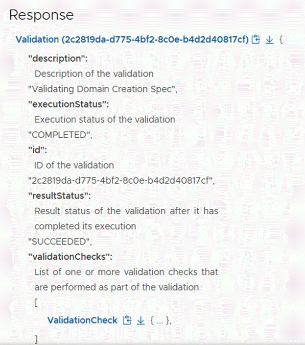
Step 9. Click to expand POST /v1/domains.
Step 10. Copy and paste the specification JSON file in the domainCreationSpec box.
Step 11. Click EXECUTE.
Step 12. Click CONTINUE to proceed with domain creation.
Step 13. It will take a while for SDDC manager to deploy the VI workload domain. Customers can look at the Task panel in SDDC manager to check the current task being executed.
Note: Customers can also log into the management vCenter to check on vCenter and NSX-T VM deployment.
On successful deployment of the VI workload domain, a vCenter and 3 NSX controller VMs will be deployed on the VMware Cloud Foundation management domain as shown in Figure 11.
Note: In a customer environment, the size of the VMs shown in Figure 11 can be different depending on the size of the deployment selected during workload domain deployment.
Step 14. Log into the VMware SDDC manager and navigate to Inventory > Workload Domains to find various deployment parameters for the newly created VI workload domain.
Step 15. Click on the workload domain name to gather more information about NSX Manager IP address and host information.
Step 16. From the VI workload domain page, click on Clusters in the main window and select the WD cluster.
Step 17. Click ACTIONS next to the cluster name and select Open in vSphere Client.
Step 18. Log into the vCenter deployed for the VI workload domain.
Now the VMware Cloud Foundation deployment is complete, and the VI workload domain is onboarded.
FlexPod VI Workload Domain Configuration
This chapter contains the following:
● Finalize the VI Workload Domain ESXi Host Configuration
● Finalize the ONTAP Configuration
After successfully adding the FlexPod hosts as VMware Cloud Foundation VI workload domain, following additional configuration steps need to be completed on ESXi hosts and the NetApp controllers.
Finalize the VI Workload Domain ESXi Host Configuration
The following configuration steps need to be completed on all the workload domain ESXi hosts:
● Mount additional NFS datastore(s) including a datastore for swap files
● Change the swap file location on the ESXi hosts
● Configure the ESXi hosts power policy
● Add application port-groups to VDS
● Backup ESXi host keys for migration or host restoration after failure
Procedure 1. Mount additional NFS datastore(s) on the VI Workload Domain Hosts
Step 1. From the Web Navigator left navigation pane, select the correct data center, and select the Datastores tab.
Step 2. Right-click on data center and select Storage > New Datastore... to add new datastore.
Step 3. In the New datastore popup, select NFS and click NEXT.
Step 4. Select the appropriate NFS version (for example, NFS 3) and click NEXT.
Step 5. Enter infra_swap for the datastore name, /infra_swap for folder and IP address of NetApp nfs-lif-01 LIF for the NFS server. Click NEXT.
Step 6. Select all the VI workload domain ESXi hosts and click NEXT.
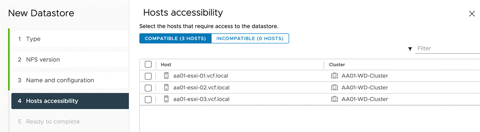
Step 7. Verify the information and click FINISH.
The datastore now appears in the datastore list.
Step 8. Repeat this procedure for any additional datastores.
Procedure 2. Configure System Swap Location on the ESXi Host(s)
Step 1. In the VI workload domain vCenter Interface, under Hosts and Clusters select the ESXi host.
Step 2. In the center pane, select the Configure tab.
Step 3. In the list under System, select System Swap.
Step 4. In the right pane, click EDIT.
Step 5. Select Can use datastore and select infra_swap from the drop-down list.
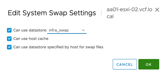
Step 6. Click OK to save the configuration changes.
Step 7. Repeat this procedure for all the ESXi hosts.
Procedure 3. Configure VM Swap File Location
Step 1. In the VI workload vCenter Interface, under Hosts and Clusters select the ESXi host.
Step 2. In the center pane, select the Configure tab.
Step 3. In the list under Virtual Machines, select Swap File Location.
Step 4. In the window on the right, click EDIT.
Step 5. Select Use a specific datastore and select infra_swap.
Step 6. Click OK to save the configuration changes.
Step 7. Repeat this procedure for all the ESXi hosts.
Procedure 4. Configure Host Power Policy on the ESXi Host
Note: Implementation of this policy is recommended in Performance Tuning Guide for Cisco UCS M6 Servers: https://www.cisco.com/c/en/us/products/collateral/servers-unified-computing/ucs-b-series-blade-servers/performance-tuning-guide-ucs-m6-servers.html for maximum VMware ESXi performance.
Note: The steps below provide a high performance policy selection which requires results in high power consumption. Customers can adjust this policy based on their requirements to reduce the power usage.
Step 1. In the VI workload vCenter Interface, under Hosts and Clusters select the ESXi host.
Step 2. In the center pane, select the Configure tab.
Step 3. In the center pane, select Hardware > Overview.
Step 4. Scroll down and click EDIT POWER POLICY under Power Management.
Step 5. Select High performance.
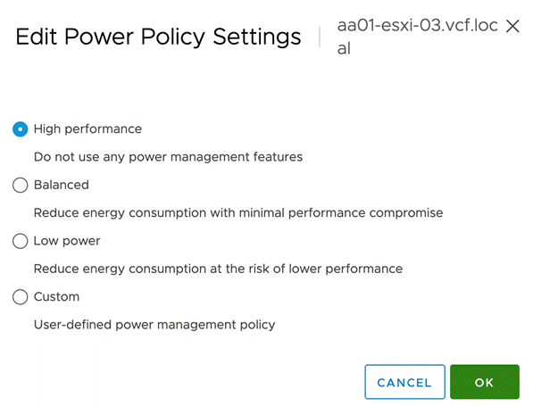
Step 6. Click OK to save the configuration changes.
Step 7. Repeat steps 1 – 6 for all the ESXi hosts.
Procedure 5. Configure the Application port-group on VDS (optional)
VMware Cloud Foundation deploys NSX-T controllers and integrates NSX with the VDS (vds02) as part of VCF deployment. Customers can start using NSX-T to route and control their application traffic.
Note: NSX configuration is not part of this deployment guide.
This procedure explains setting up traditional VLAN based application networking. Customers can utilize application port-groups, defined on the VDS (vds02), to attach their application VMs to various VLANs. In the procedure below, a single application VLAN (1012) will be added to a port-group defined on VDS vds02. This port-group will allow application VMs to communicate with the enterprise network using the gateway defined on the Cisco Nexus switches.
Step 1. Log into the VI workload domain vCenter.
Step 2. Select Networking under Menu and expand the appropriate datacenter.
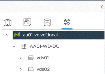
Step 3. Click the VDS vds02.
Step 4. Right-click and select Distributed Port Group > New Distributed Port Group.
Step 5. Provide a Name (for example, App-PG) and click NEXT.
Step 6. For the VLAN type, select VLAN from the drop-down list.
Step 7. Enter the Application VLAN ID (for example, 1012) and click NEXT.
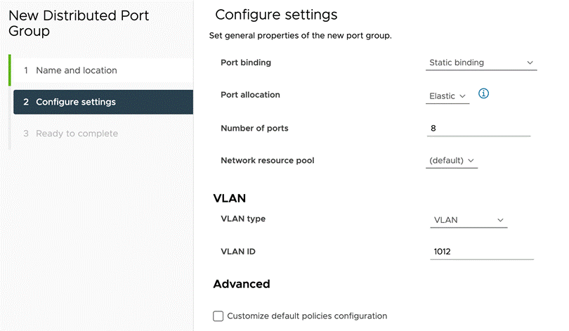
Step 8. Review the configuration and click FINISH.
Step 9. Repeat these steps for all the application VLANs.
Procedure 6. Backup the ESXi Recovery Keys
FlexPod ESXi hosts are configured for boot from SAN using Fibre Channel which allows stateless compute setup. The stateless compute allows a server profile to move from one compute node to another seamlessly in case of failure or hardware upgrade. Starting with ESXi 7.0 Update 2, compute nodes containing a Trusted Platform Module (TPM) and configured for UEFI boot save the sensitive information in the TPM and require a recovery key to successfully migrate or recover the ESXi host on a new/different compute node. This procedure explains backing up of the recovery keys from all the VI workload domain ESXi hosts.
Step 1. Log into Cisco Intersight and select Infrastructure Service.
Step 2. Click on Servers.
Step 3. Select the VI workload domain ESXi server and click … and select Launch vKVM.
Step 4. Click through the certificate prompts and lunch the KVM.
Step 5. Press F2 and log into the ESXi host using root.
Step 6. Scroll down to Troubleshooting Mode Options and select Enable SSH.
Step 7. Connect to the management IP address of the ESXi host using an SSH client.
Step 8. Use root as username and password set for the host.
Step 9. Issue the following command on the ESXi host CLI:
[root@aa01-esxi-01:~] esxcli system settings encryption recovery list
Recovery ID Key
-------------------------------------- ---
{54B47EDC-EEE3-4949-86B6-758633DA312B} 240691-xxxxxx-112774-307101-xxxxxx-339487-xxxxxx-362831-xxxxxx-354968-xxxxxx-091124-xxxxxx-312259-xxxxxx-390449
Step 10. Save the recovery key in a safe location.
Step 11. Exit the SSH session.
Step 12. Log back into the KVM console for the host and disable SSH.
Step 13. Close the KVM console.
Procedure 7. Using the Recovery Keys for Server Profile Migration or Recovery on a New Compute Node
To recover the ESXi configuration when migrating ESXi host from one compute node to another, refer to this VMware article: https://docs.vmware.com/en/VMware-vSphere/7.0/com.vmware.vsphere.security.doc/GUID-23FFB8BB-BD8B-46F1-BB59-D716418E889A.html#GUID-23FFB8BB-BD8B-46F1-BB59-D716418E889A.
Step 1. After associating the server profile with new compute node, log into Intersight and launch the KVM console for the server.
Step 2. Boot the server and stop the boot process by pressing Shift + O at the ESXi boot screen.
Step 3. Type encryptionRecoveryKey= in the KVM console.
Step 4. Retrieve the recovery key from the previously stored safe location and copy it to clipboard.
Step 5. On the KVM console, select File > Paste Clipboard Text.
Step 6. Paste the contents of the recovery key to add them immediately after encryptionRecoveryKey=.

Step 7. Once the recovery key is posted correctly, press Enter to continue.
Step 8. If the new compute node needs to be permanently associated with the server profile, SSH into the ESXi host (might need to enable SSH as covered above) and issue the following command:
[root@aa01-esxi-01:~] /sbin/auto-backup.sh
Note: If a recovery key is not provided during serve profile migration, following output is observed on the KVM console:
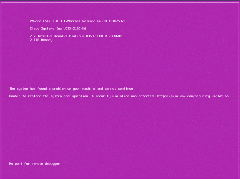
Finalize the ONTAP Configuration
The following configuration steps need to be completed on the NetApp controllers:
● Configure DNS
● Enable audit configuration for the SVM
● Delete default residual domains
● Test auto support configuration
Procedure 1. Configure DNS
Step 1. To configure DNS for the Infra-SVM, run the following commands:
dns create -vserver <vserver name> -domains <dns-domain> -nameserve <dns-servers>
Example:
dns create -vserver Infra-SVM -domains vcf.local -nameservers 10.101.1.53,10.101.1.54
Procedure 2. Create and enable auditing configuration for the SVM
Step 1. To create auditing configuration for the SVM, run the following command:
vserver audit create -vserver Infra-SVM -destination /audit_log
Step 2. Run the following command to enable audit logging for the SVM:
vserver audit enable -vserver Infra-SVM
Note: It is recommended that you enable audit logging so you can capture and manage important support and availability information. Before you can enable auditing on the SVM, the SVM’s auditing configuration must already exist. If the users do not perform the above configuration steps for the SVM, they will observe a warning in AIQUM stating “Audit Log is disabled.”
Procedure 3. Delete Residual Default Domains (Applicable for 2-node cluster only)
Step 1. To delete the Default domains that are not in use, run the following commands:
broadcast-domain delete -broadcast-domain <broad-domain-name>
Use the following command to find unused default domains:
broadcast-domain show
Example:
broadcast-domain delete -broadcast-domain Default-1
broadcast-domain delete -broadcast-domain Default-2
Procedure 4. Test Auto Support
Step 1. To test the Auto Support configuration by sending a message from all nodes of the cluster, run the following commands:
autosupport invoke -node * -type all -message “FlexPod storage configuration completed”
FlexPod Management Tools Setup
This chapter contains the following:
● NetApp ONTAP Tools 9.11 Deployment
● Provision Datastores using ONTAP Tools (Optional)
● NetApp SnapCenter 4.7 Installation
● NetApp SnapCenter 4.7 Configuration
● Active IQ Unified Manager 9.11P1 Installation
● Configure Active IQ Unified Manager
● Deploy Cisco Intersight Assist Appliance
● Claim NetApp Active IQ Manager using Cisco Intersight Assist Appliance
● Claim Cisco Nexus Switches using Cisco Intersight Assist Appliance
● Claim Cisco MDS Switches using Cisco Intersight Assist Appliance
● Create a FlexPod XCS Integrated System
This chapter explains the various management tools that will be installed for configuring and managing FlexPod VI workload domain hosts and infrastructure.
NetApp ONTAP Tools 9.11 Deployment
The ONTAP tools for VMware vSphere provide end-to-end life cycle management for virtual machines in VMware environments that use NetApp storage systems. It simplifies storage and data management for VMware environments by enabling administrators to directly manage storage within the vCenter Server. To get detailed info about NetApp ONTAP Tools, go here.
Procedure 1. Install NetApp ONTAP Tools
NetApp ONTAP Tools VM will be deployed on the VMware Cloud Foundation management domain vCenter using vSAN datastore.
Step 1. Download the NetApp ONTAP Tools 9.11 OVA (NETAPP-ONTAP-TOOLS-FOR-VMWARE-VSPHERE-9.11-8450.OVA) from NetApp support: https://mysupport.netapp.com/site/products/all/details/otv/downloads-tab/download/63792/9.11
Step 2. Launch the vSphere Web Client and navigate to Hosts and Clusters.
Step 3. Select ACTIONS for the FlexPod-DC datacenter and select Deploy OVF Template.
Step 4. Browse to the ONTAP tools OVA file and select the file.
Step 5. Enter the VM name and select a datacenter or folder to deploy the VM and click NEXT.
Step 6. Select a host cluster resource to deploy OVA and click NEXT.
Step 7. Review the details and accept the license agreement.
Step 8. Select the VSAN volume and Select the Thin Provision option for the virtual disk format.
Step 9. From Select Networks, select a destination network (typically in-band management network) and click NEXT.
Step 10. From Customize Template, enter the ONTAP tools administrator password, Workload Domain vCenter name or IP address and other configuration details and click NEXT.
Note: It is important to remember that while the ONTAP tools VM is being deployed (hosted) on the VMware Cloud Foundation management domain, select the FlexPod Workload Domain vCenter for ONTAP tool integration because NetApp storage is attached to hosts managed by the Workload Domain vCenter.
Step 11. Review the configuration details entered and click FINISH to complete the deployment of NetApp ONTAP-Tools VM.
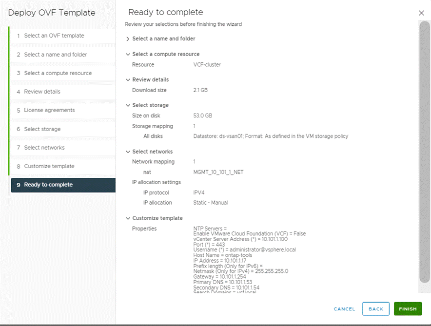
Step 12. Power on the ONTAP-tools VM and open the VM console.
Step 13. During the ONTAP-tools VM boot process, you see a prompt to install VMware Tools. From vCenter, right-click the ONTAP-tools VM > Guest OS > Install VMware Tools.
Step 14. Networking configuration and vCenter registration information was provided during the OVF template customization, therefore after the VM is up and running, ONTAP-Tools and vSphere API for Storage Awareness (VASA) is registered with vCenter.
Step 15. Using a web browser, log into the workload domain vCenter.
Step 16. Refresh the vCenter Home Screen and confirm that the ONTAP tools is installed.
Note: The NetApp ONTAP tools vCenter plug-in is only available in the vSphere HTML5 Client and is not available in the vSphere Web Client.
Procedure 2. Download the NetApp NFS Plug-in for VAAI
The NFS Plug-in for VAAI was previously installed on the ESXi hosts along with the Cisco UCS VIC drivers; it is not necessary to re-install the plug-in at this time. However, for any future additional ESXi host setup, instead of using esxcli commands, NetApp ONTAP-Tools can be utilized to install the NetApp NFS plug-in. The steps below upload the latest version of the plugin to ONTAP tools.
Step 1. Download the NetApp NFS Plug-in 2.0 for VMware file from: https://mysupport.netapp.com/site/products/all/details/nfsplugin-vmware-vaai/downloads-tab.
Step 2. Unzip the file and extract NetApp_bootbank_NetAppNasPlugin_2.0-15.vib from vib20 > NetAppNasPlugin.
Step 3. Rename the .vib file to NetAppNasPlugin.vib to match the predefined name that ONTAP tools uses.
Step 4. On the workload domain vCenter, click Settings under the ONTAP tool Getting Started page.
Step 5. Click NFS VAAI tools tab.
Step 6. Click Change in the Existing version section.
Step 7. Browse and select the renamed .vib file, and then click Upload to upload the file to the virtual appliance.

Note: The next step is only required on the hosts where NetApp VAAI plug-in was not installed alongside Cisco VIC driver installation on the workload domain hosts.
Step 8. In the Install on ESXi Hosts section, select the workload domain ESXi host where the NFS Plug-in for VAAI is to be installed, and then click Install.
Step 9. Reboot the ESXi host after the installation finishes.
Procedure 3. Verify the VASA Provider
The VASA provider for ONTAP is enabled by default during the installation of the NetApp ONTAP tools.
Step 1. From the workload domain vSphere Client, click Menu > ONTAP tools.
Step 2. Click Settings.
Step 3. Click Manage Capabilities in the Administrative Settings tab.
Step 4. In the Manage Capabilities dialog box, click Enable VASA Provider if it was not pre-enabled.
Step 5. Enter the IP address of the virtual appliance for ONTAP tools, VASA Provider, and VMware Storage Replication Adapter (SRA) and the administrator password, and then click Apply.
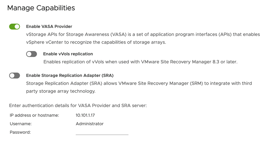
Procedure 4. Discover and Add Storage Resources
Step 1. Using the vSphere Web Client, log in to the workload domain vCenter. If the vSphere Web Client was previously opened, close the tab, and then reopen it.
Step 2. In the Home screen, click the Home tab and click ONTAP tools.
Note: When using the cluster admin account, add storage from the cluster level.
Note: You can modify the storage credentials with the vsadmin account or another SVM level account with role-based access control (RBAC) privileges. Refer to the ONTAP 9 Administrator Authentication and RBAC Power Guide for additional information.
Step 3. Click on Storage Systems, and then click ADD under Add Storage System.
Step 4. Specify the vCenter Server where the storage will be located.
Step 5. In the Name or IP Address field, enter the storage cluster management IP.
Step 6. Enter admin for the username and the admin password for the cluster.
Step 7. Confirm Port 443 to Connect to this storage system.
Step 8. Click ADD to add the storage configuration to ONTAP tools.
Step 9. Wait for the Storage Systems to update. You might need to click Refresh to complete this update.
Step 10. From the workload domain vCenter vSphere Client Home page, click Hosts and Clusters.
Step 11. Right-click the FlexPod-DC datacenter, click NetApp ONTAP tools > Update Host and Storage Data.

Step 12. On the Confirmation dialog box, click OK. It might take a few minutes to update the data.
Procedure 5. Optimal Storage Settings for ESXi Hosts
ONTAP tools enables the automated configuration of storage-related settings for all ESXi hosts that are connected to NetApp storage controllers.
Step 1. From the workload domain VMware vSphere Web Client Home page, click vCenter > Hosts and Clusters.
Step 2. Select a host and then click Actions > NetApp ONTAP tools > Set Recommended Values.
Step 3. In the NetApp Recommended Settings dialog box, select all the applicable values for the ESXi host.
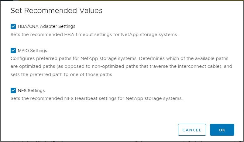
Note: This functionality sets values for HBAs and converged network adapters (CNAs), sets appropriate paths and path-selection plug-ins, and verifies appropriate settings for NFS I/O. A vSphere host reboot may be required after applying the settings.
Step 4. Click OK.
Provision Datastores using ONTAP Tools (Optional)
Using ONTAP tools, the administrator can provision an NFS, FC, FC-NVMe or iSCSI datastore and attach it to a single or multiple hosts in the cluster. The following steps describe provisioning a datastore and attaching it to the cluster.
Note: It is a NetApp best practice to use ONTAP tools to provision any additional datastores for the FlexPod infrastructure. When using VSC to create vSphere datastores, all NetApp storage best practices are implemented during volume creation and no additional configuration is needed to optimize performance of the datastore volumes
Storage Capabilities
A storage capability is a set of storage system attributes that identifies a specific level of storage performance (storage service level), storage efficiency, and other capabilities such as encryption for the storage object that is associated with the storage capability.
Create the Storage Capability Profile
To leverage the automation features of VASA two primary components must first be configured. The Storage Capability Profile (SCP) and the VM Storage Policy. The Storage Capability Profile expresses a specific set of storage characteristics into one or more profiles used to provision a Virtual Machine. The SCP is specified as part of VM Storage Policy. NetApp ONTAP tools comes with several pre-configured SCPs such as Platinum, Bronze, and so on.
Note: The ONTAP tools for VMware vSphere plug-in also allow you to set Quality of Service (QoS) rule using a combination of maximum and/or minimum IOPs.
Procedure 1. Review or Edit the Built-In Profiles Pre-Configured with ONTAP Tools
Step 1. From the workload domain vCenter console, click Menu > ONTAP tools.
Step 2. In the NetApp ONTAP tools click Storage Capability Profiles.
Step 3. Select the Platinum Storage Capability Profile and select Clone from the toolbar.
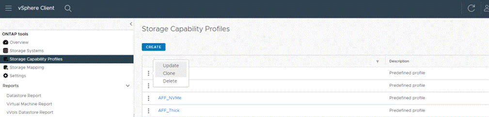
Step 4. Select All Flash FAS(AFF) for the storage platform and click NEXT.
Step 5. Select Any for the protocol and click Next.
Note: You can set traditional QoS policies for your storage system by using the Performance tab.
Step 6. Select None to allow unlimited performance or when QoS policy is selected then a traditional QoS policy is applied to a VVol.
Step 7. You can set a the desired minimum and maximum IOPS for the QoS policy group to use the QoS functionality. Click NEXT.
Step 8. On the Storage attributes page, change the Encryption and Tiering policy to the desired settings and click NEXT. In the example below, Encryption was turned.
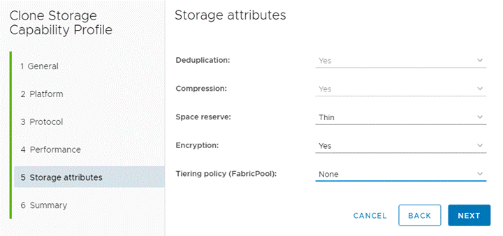
Step 9. Review the summary page and click FINISH to create the storage capability profile.
Procedure 2. Provision NFS Datastore
Step 1. From the workload domain vCenter console, click Menu > ONTAP tools.
Step 2. From the ONTAP tools Home page, click Overview.
Step 3. In the Getting Started tab, click Provision.
Step 4. Click Browse to select the destination to provision the datastore.
Step 5. Select the type as NFS and Enter the datastore name (for example, NFS_DS_1).
Step 6. Provide the size of the datastore and the NFS Protocol.
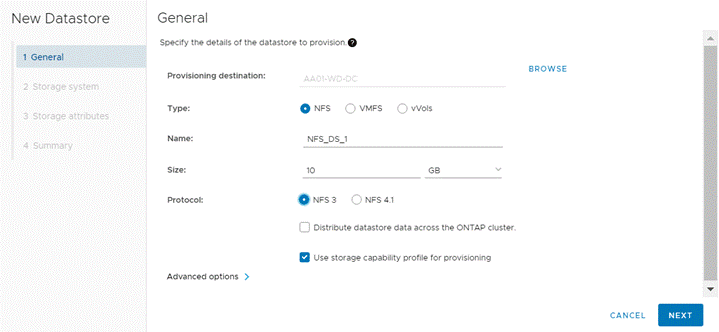
Step 7. Check the storage capability profile and click NEXT.
Step 8. Select the desired Storage Capability Profile, cluster name and the desired SVM to create the datastore. In this example, the Infra-SVM is selected.
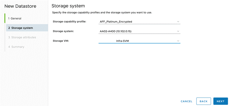
Step 9. Click NEXT.
Step 10. Select the aggregate name and click NEXT.
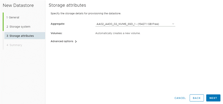
Step 11. Review the Summary and click FINISH.
Note: The datastore is created and mounted on the hosts in the cluster. Click Refresh from the vSphere Web Client to see the newly created datastore.
NetApp SnapCenter 4.7 Installation
SnapCenter Software is a centralized and scalable platform that provides application-consistent data protection for applications, databases, host file systems, and VMs running on ONTAP systems anywhere in the Hybrid Cloud.
NetApp SnapCenter Architecture
The SnapCenter platform is based on a multitier architecture that includes a centralized management server (SnapCenter Server) and a SnapCenter host agent. The host agent that performs virtual machine and datastore backups for VMware vSphere is the SnapCenter Plug-in for VMware vSphere. It is packaged as a Linux appliance (Debian-based Open Virtual Appliance format) and is no longer part of the SnapCenter Plug-ins Package for Windows. Additional information on deploying SnapCenter server for application backups can be found in the documentation listed below.
This guide focuses on deploying and configuring the SnapCenter plug-in for VMware vSphere to protect virtual machines and VM datastores.
Note: You must install SnapCenter Server and the necessary plug-ins to support application-consistent backups for Microsoft SQL, Microsoft Exchange, Oracle databases and SAP HANA. Application-level protection is beyond the scope of this deployment guide.
Refer to the SnapCenter documentation for more information or the application specific CVD’s and technical reports for detailed information on how to deploy SnapCenter for a specific application configuration:
● SnapCenter Documentation: https://docs.netapp.com/us-en/snapcenter/index.html
● Deploy FlexPod Datacenter for Microsoft SQL Server 2019 with VMware 7.0 on Cisco UCS B200 M6 and NetApp ONTAP 9.8:
https://www.cisco.com/c/en/us/products/collateral/servers-unified-computing/ucs-b-series-blade-servers/flexpod-sql-2019-vmware-on-ucs-netapp-ontap-wp.html
● SnapCenter Plug-in for VMware vSphere Documentation: https://mysupport.netapp.com/documentation/docweb/index.html?productID=63990&language=en-US
Host and Privilege Requirements for the SnapCenter Plug-In for VMware vSphere
Review the following requirements before installing the SnapCenter Plug-in for VMware vSphere virtual appliance:
● SnapCenter Plug-in for VMware vSphere is deployed as a Linux based virtual appliance.
● Virtual appliance must not be deployed in a folder name with special characters.
● A separate, unique instance of the virtual appliance must be deployed for each vCenter Server.
Procedure 1. Download and Deploy the SnapCenter Plug-In for VMware vSphere 4.7
SnapCenter Plugin VM will be deployed on the VMware Cloud Foundation management domain vCenter using the vSAN datastore.
Step 1. Download SnapCenter Plug-in for VMware vSphere OVA file from NetApp support site (https://mysupport.netapp.com).
Step 2. From VMware vCenter, navigate to the VMs and Templates tab, right-click the data center (for example, VCF-mgmt) and select Deploy OVF Template.
Step 3. Specify the location of the OVF Template and click NEXT.
Step 4. On the Select a name and folder page, enter a unique name (for example, snapcenter-vm) and location (data center for example, VCF-mgmt) for the VM and click NEXT to continue.
Step 5. On the Select a compute resource page, select the cluster, and click NEXT.
Step 6. On the Review details page, verify the OVA template details and click NEXT.
Step 7. On the License agreements page, read and check the box I accept all license agreements. Click NEXT.
Step 8. On the Select storage page, select a datastore, change the datastore virtual disk format to Thin Provision and click NEXT.
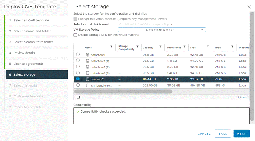
Step 9. On the Select networks page, select destination network (for example IB-Mgmt), and click NEXT.
Step 10. On the Customize template page, under Register to existing vCenter, enter the vcf workload domain vCenter credentials.
Note: Even though the SnapCenter VM is being deployed on the management domain vCenter, the SnapCenter will be registered to the FlexPod workload domain vCenter.
Step 11. In Create SCV credentials, create a username (for example, admin) and password for the SCV maintenance user.
Step 12. In Setup Network Properties, enter the network information.
Step 13. In Setup Date and Time, provide the NTP server address(es) and select the time zone.
Step 14. Click NEXT.
Step 15. On the Ready to complete page, review the page and click FINISH. The VM deployment will start. After the VM is deployed successfully, proceed to the next step.
Step 16. Navigate to the SnapCenter VM, right click, and select Power > Power On to start the virtual appliance.
Step 17. While the virtual appliance is powering on, click Install VMware tools.
Step 18. After the SnapCenter VM installation is complete and VM is ready to use, proceed to the next step.
Step 19. Log into SnapCenter Plug-in for VMware vSphere using the IP address (https://<ip_address_of_SnapCenter>:8080) displayed on the appliance console screen with the credentials that were configured in the deployment wizard.
Step 20. Verify on the Dashboard that the virtual appliance has successfully connected to vCenter and the SnapCenter Plug-in for VMware vSphere is successfully enabled and connected.
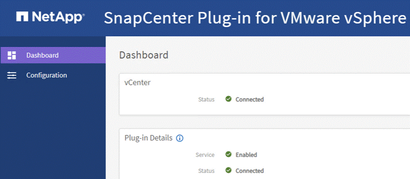
NetApp SnapCenter 4.7 Configuration
Procedure 1. SnapCenter Plug-In for VMware vSphere in vCenter Server
Step 1. Navigate to FlexPod workload domain vCenter URL: https://<vCenter Server>
Note: If currently logged into vCenter, logoff, close the open tab and sign-on again to access the newly installed SnapCenter Plug-in for VMware vSphere.
Step 2. After logging in, a blue banner will be displayed indicating the SnapCenter plug-in was successfully deployed. Click Refresh to activate the plug-in.
Step 3. Select Menu > SnapCenter Plug-in for VMware vSphere to launch the SnapCenter Plug-in for VMware GUI.
Procedure 2. Add Storage System
Step 1. Click Storage Systems.
Step 2. Click +Add to add a storage system (or SVM).
Step 3. Enter Storage System, user credentials, and other required information in the dialog box.
Step 4. Check the box for Log SnapCenter server events to syslog and Send AutoSupport Notification for failed operation to storage system.
Step 5. Click ADD.
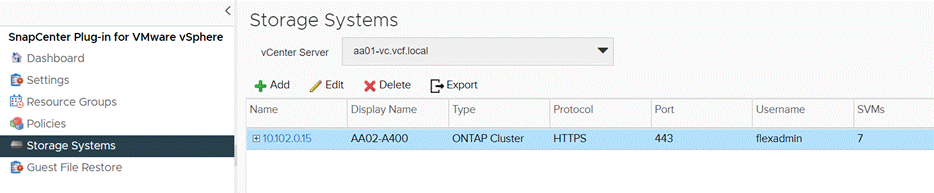
Once the storage system is added, you can create backup policies and take scheduled backup of VMs and datastores. The SnapCenter plug-in for VMware vSphere allows backup, restore and on-demand backups. To set up the backup policy and related configuration, complete the steps explained here: https://www.cisco.com/c/en/us/td/docs/unified_computing/ucs/UCS_CVDs/flexpod_xseries_vmware_7u2.html#NetAppSnapCenter45configuration.
Active IQ Unified Manager 9.11P1 Installation
Active IQ Unified Manager enables customers to monitor and manage the health and performance of ONTAP storage systems and virtual infrastructure from a single interface. Unified Manager provides a graphical interface that displays the capacity, availability, protection, and performance status of the monitored storage systems. Active IQ Unified Manager is required to integrate NetApp storage with Cisco Intersight. To get detailed info about AIQUM, please visit AIQUM.
Procedure 1. Install NetApp Active IQ Unified Manager
NetApp Active IQ Unified Manager VM will be deployed on the VMware Cloud Foundation management domain vCenter using the vSAN datastore.
Step 1. Download NetApp Active IQ Unified Manager for VMware vSphere OVA file from: https://mysupport.netapp.com/site/products/all/details/activeiq-unified-manager/downloads-tab.
Step 2. In the VCF management domain VMware vCenter GUI, click VMs and Templates and then click Actions> Deploy OVF Template.
Step 3. Specify the location of the OVF Template and click NEXT.
Step 4. On the Select a name and folder page, enter a unique name for the VM, and select a deployment location, and then click NEXT.
Step 5. On the Select a compute resource screen, select the cluster where VM will be deployed and click NEXT.
Step 6. On the Review details page, verify the OVA template details and click NEXT.
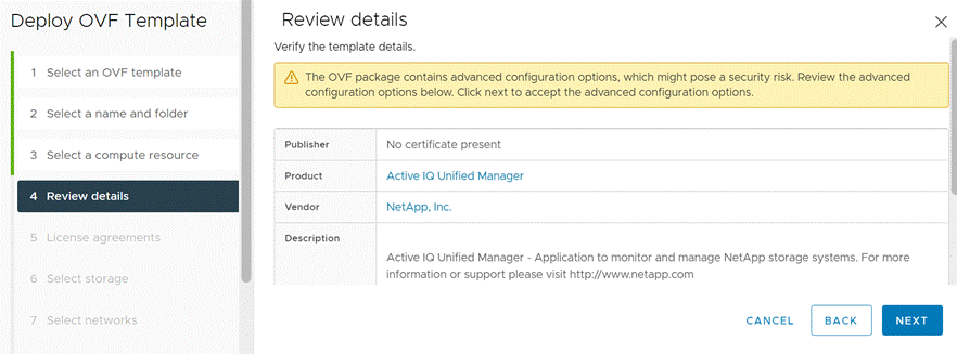
Step 7. On the License agreements page, read and check the box for I accept all license agreements. Click NEXT.
Step 8. On the Select storage page, select following parameters for the VM deployment:
a. Select a VM Storage Policy (for example, Datastore Default).
b. Select a datastore to store the deployed OVA template.
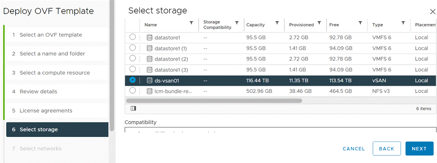
Step 9. Click NEXT.
Step 10. On the Select networks page, select the destination network (for example, IB-Mgmt) and click NEXT.
Step 11. On the Customize template page, provide network details such as hostname, IP address, gateway, and DNS.
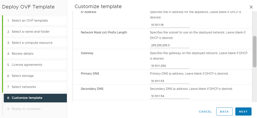
Step 12. Leave TimeZone value field blank but enter Maintenance username and password.
Note: Save the maintenance user account credentials in a secure location. These credentials will be used for the initial GUI login and to make any configuration changes to the appliance settings in future.
Step 13. Click NEXT.
Step 14. On the Ready to complete page, review the settings and click FINISH. Wait for the VM deployment to complete before proceeding to the next step.
Step 15. Select the newly created Active IQ Unified Manager VM, right-click and select Power > Power On.
Step 16. While the virtual machine is powering on, click the prompt in the yellow banner to Install VMware tools.
Note: Because of timing, VMware tools might not install correctly. In that case VMware tools can be manually installed after Active IQ Unified Manager VM is up and running.
Step 17. Open the VM console for the Active IQ Unified Manager VM and configure the time zone information when displayed.
Step 18. Wait for the AIQM web console to display the login prompt.
Step 19. Log into NetApp Active IQ Unified Manager using the IP address or URL displayed on the web console.
Configure Active IQ Unified Manager
Procedure 1. Initial Setup
Step 1. Launch a web browser and log into Active IQ Unified Manger using the URL shown in the VM console.
Step 2. Enter the email address that Unified Manager will use to send alerts and the mail server configuration. Click Continue.
Step 3. Select Agree and Continue on the Set up AutoSupport configuration.
Step 4. Check the box for Enable API Gateway and click Continue.
Step 5. Enter the ONTAP cluster hostname or IP address and the admin login credentials.
Step 6. Click Add.
Step 7. Click Yes to trust the self-signed cluster certificate and finish adding the storage system.
Note: The initial discovery process can take up to 15 minutes to complete.
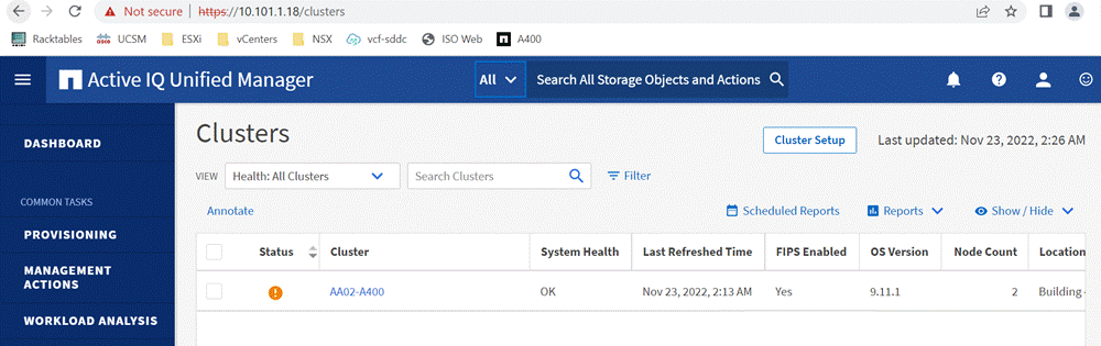
To configure and review the Security Compliance with Active IQ Unified Manager and Remediate Security Compliance Findings, complete the steps here: https://www.cisco.com/c/en/us/td/docs/unified_computing/ucs/UCS_CVDs/flexpod_xseries_vmware_7u2.html#ActiveIQUnifiedManager99P1Installation.
Deploy Cisco Intersight Assist Appliance
Cisco Intersight works with NetApp’s ONTAP storage and VMware vCenter using third-party device connectors and Cisco Nexus and MDS switches using Cisco device connectors. Since third-party infrastructure and Cisco switches do not contain any usable built-in Intersight device connector, Cisco Intersight Assist virtual appliance enables Cisco Intersight to communicate with these devices.
Note: A single Cisco Intersight Assist virtual appliance can support NetApp ONTAP storage, VMware vCenter, Cisco Nexus, and Cisco MDS switches as shown in Figure 12.
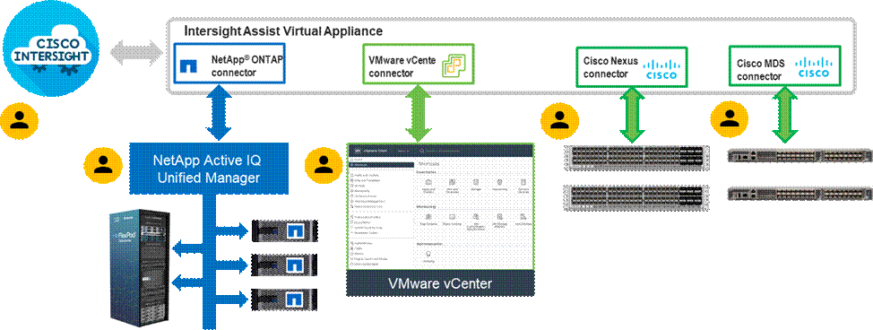
Procedure 1. Download Cisco Intersight Assist
To install Cisco Intersight Assist from an Open Virtual Appliance (OVA), download the latest release of the Cisco Intersight Virtual Appliance for vSphere from https://software.cisco.com/download/home/286319499/type/286323047/release/1.0.9-342?catid=268439477
Procedure 2. Deploy Cisco Intersight Assist appliance
Cisco Intersight Assist appliance VM will be deployed on the VMware Cloud Foundation management domain vCenter using the vSAN datastore. To install the Cisco Intersight Assist appliance, follow the steps here: https://www.cisco.com/c/en/us/td/docs/unified_computing/ucs/UCS_CVDs/flexpod_xseries_vmware_7u2.html#DeployCiscoIntersightAssistAppliance
Claim VMware vCenter using Cisco Intersight Assist Appliance
Procedure 1. Claim the vCenter
Step 1. Log into Cisco Intersight and connect to the account for this FlexPod.
Step 2. Select System > Administration > Targets and click Claim a New Target.
Step 3. Under Select Target Type, select VMware vCenter under Hypervisor and click Start.
Step 4. In the VMware vCenter window, verify the correct Intersight Assist is selected.
Step 5. Fill in the vCenter information. If Intersight Workflow Optimizer (IWO) will be used, turn on Datastore Browsing Enabled and Guest Metrics Enabled. If it is desired to use Hardware Support Manager (HSM) to be able to upgrade IMM server firmware from VMware Lifecycle Manager, turn on HSM. Click Claim.
Step 6. After a few minutes, the VMware vCenter will show Connected in the Targets list and will also appear under Infrastructure Service > Operate > Virtualization.
Step 7. Detailed information obtained from the vCenter can now be viewed by clicking Infrastructure Service > Operate > Virtualization and selecting the Datacenters tab. Other VMware vCenter information can be obtained by navigating through the Virtualization tabs.
Claim NetApp Active IQ Manager using Cisco Intersight Assist Appliance
Procedure 1. Claim the NetApp Active IQ Unified Manager
Step 1. Log into Cisco Intersight.
Step 2. From Cisco Intersight, click System > Administration > Targets.
Step 3. Click Claim a New Target. In the Select Target Type window, select NetApp Active IQ Unified Manager under Storage and click Start.
Step 4. In the Claim NetApp Active IQ Unified Manager Target window, verify the correct Intersight Assist is selected.
Step 5. Fill in the NetApp Active IQ Unified Manager information and click Claim.
Step 6. After a few minutes, the NetApp ONTAP Storage configured in the Active IQ Unified Manager will appear under Infrastructure Service > Operate > Storage tab.
Step 7. Click on the storage cluster name to see detailed General, Inventory, and Checks information on the storage.
Claim Cisco Nexus Switches using Cisco Intersight Assist Appliance
Procedure 1. Claim Cisco Nexus Switches
Step 1. Log into Cisco Intersight and click System > Administration > Targets.
Step 2. Click Claim a New Target. In the Select Target Type window, select Cisco Nexus Switch under Network and click Start.
Step 3. In the Claim Cisco Nexus Switch Target window, verify the correct Intersight Assist is selected.
Step 4. Fill in the Cisco Nexus Switch information and click Claim.
Note: You can use the admin user on the switch.
Step 5. Repeat this procedure to add the second Cisco Nexus Switch.
After a few minutes, the two switches will appear under Infrastructure Service > Operate > Networking > Ethernet Switches.
Claim Cisco MDS Switches using Cisco Intersight Assist Appliance
Procedure 1. Claim Cisco MDS Switches
Step 1. Log into Cisco Intersight and connect to the account for this FlexPod.
Step 2. From Cisco Intersight, click System > Administration > Targets.
Step 3. Click Claim a New Target. In the Select Target Type window, select Cisco MDS Switch under Network and click Start.
Step 4. In the Claim Cisco MDS Switch Target window, verify the correct Intersight Assist is selected.
Step 5. Fill in the Cisco MDS Switch information including use of Port 8443 and click Claim.
Note: You can use the admin user on the switch.
Step 6. Repeat this procedure to add the second Cisco MDS Switch.
After a few minutes, the two switches will appear under Infrastructure Service > Operate > Networking > SAN Switches.
Create a FlexPod XCS Integrated System
Procedure 1. Creating a FlexPod XCS Integrated System
Step 1. Log into Cisco Intersight and click Infrastructure Service > Operate > Integrated Systems.
Step 2. Click Create Integrated System. In the center pane, select FlexPod and click Start.
Step 3. Select the correct Organization (for example, AA01), provide a suitable name, and optionally any Tags or a Description and click Next.
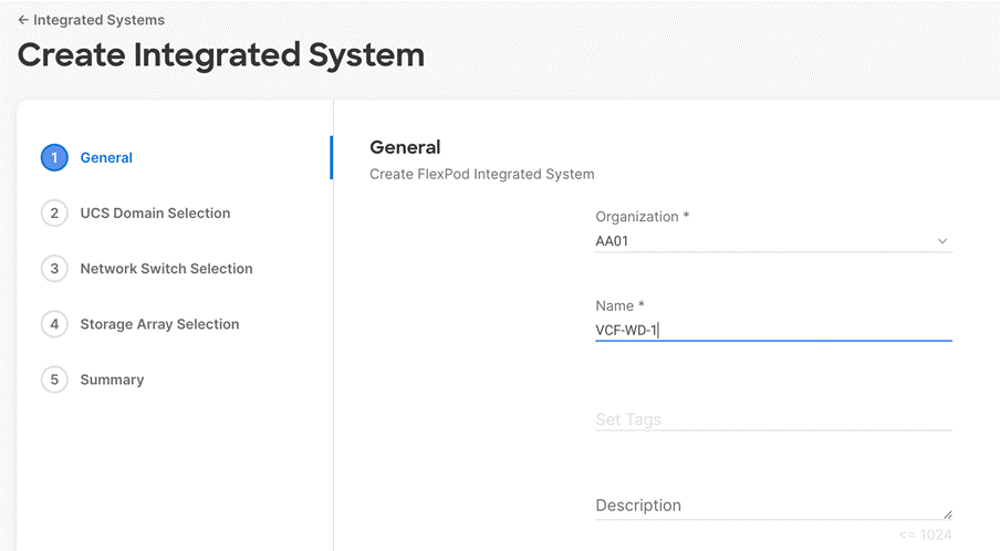
Step 4. Select the UCS Domain used in this FlexPod and click Next.
Step 5. Select the two Cisco Nexus switches used for the FlexPod workload domain and click Next.
Step 6. Select all NetApp storage used in this FlexPod and click Next.
Step 7. Look over the Summary information and click Create. After a few minutes, the FlexPod Integrated System will appear under Integrated Systems.
Step 8. Click the “…” to the right of the FlexPod name and run an Interoperability check on the FlexPod. This check will take information on the FlexPod already checked against the Cisco UCS Hardware Compatibility List (HCL) and check this information against the NetApp Interoperability Matrix Tool (IMT).
Step 9. Select My Dashboard > FlexPod to see several informational widgets on FlexPod Integrated Systems.
Conclusion
The FlexPod Datacenter solution is a validated approach for deploying Cisco and NetApp technologies and products for building shared private and public cloud infrastructure. VMware Cloud Foundation enables data center administrators to provision an application environment in a quick, repeatable, and automated manner. FlexPod as a workload domain for VMware Cloud Foundation provides following benefits in any data center environment:
● Integrated solution that supports entire VMware software defined stack
● Standardized architecture for quick, repeatable, error free deployments of FlexPod based workload domains
● Automated life cycle management to keep all the system components up to date
● Simplified cloud-based management of various FlexPod components
● Hybrid-cloud-ready, policy-driven modular design
● Highly available, flexible, and scalable FlexPod architecture
● Cooperative support model and Cisco Solution Support
● Easy to deploy, consume, and manage design which aligns with Cisco, NetApp and VMware best practices and compatibility requirements
● Support for component monitoring, solution automation and orchestration, and workload optimization
The success of the FlexPod solution is driven through its ability to evolve and incorporate both technology and product innovations in the areas of management, compute, storage, and networking and this document highlights the deployment details of incorporating FlexPod as a workload domain for VMware Cloud Foundation.
Haseeb Niazi, Principal Technical Marketing Engineer, Cisco Systems, Inc.
Haseeb Niazi has over 23 years of experience at Cisco in the Datacenter, Enterprise and Service Provider Solutions and Technologies. As a member of various solution teams and Advanced Services, Haseeb has helped many enterprise and service provider customers evaluate and deploy a wide range of Cisco solutions. As a technical marking engineer at Cisco UCS Solutions group, Haseeb focuses on network, compute, virtualization, storage, and orchestration aspects of various Compute Stacks. Haseeb holds a master's degree in Computer Engineering from the University of Southern California and is a Cisco Certified Internetwork Expert (CCIE 7848).
Ruchika Lahoti, Technical Marketing Engineer, NetApp
Ruchika has more than five years of experience in the IT industry. She focuses on FlexPod hybrid cloud infrastructure solution design, implementation, validation, and automation. Ruchika holds a bachelor’s degree in Computer Science.
Acknowledgements
For their support and contribution to the design, validation, and creation of this Cisco Validated Design, the authors would like to thank:
● John George, Technical Marketing Engineer, Cisco Systems, Inc.
● Chris Dunk, Principal Engineer, Cisco Systems, Inc.
● Abhinav Singh, Senior Technical Marketing Engineer, NetApp
This appendix is organized as follows:
● Appendix A – Workload Domain Description JSON File
● Appendix B – Ansible Automation for Solution Deployment
● Appendix C – Cisco UCS Manager Configuration for Management Domain Hosts
● Appendix D – References Used in Guide
● Appendix F – Acronym Glossary
● Appendix G – Recommended for You
Appendix A – Workload Domain Description JSON File
This appendix contains a complete JSON file for workload domain deployment.
Note: The elements marked by “<####>” have been retracted.
{
"domainName": "AA01-WD",
"vcenterSpec": {
"name": "aa01-vc",
"networkDetailsSpec": {
"ipAddress": "10.101.1.100",
"dnsName": "aa01-vc.vcf.local",
"gateway": "10.101.1.254",
"subnetMask": "255.255.255.0"
},
"rootPassword": "<####>",
"datacenterName": "AA01-WD-DC",
"vmSize": "small"
},
"computeSpec": {
"clusterSpecs": [
{
"name": "AA01-WD-Cluster",
"hostSpecs": [
{
"id": "<####>",
"licenseKey": "<####>",
"hostNetworkSpec": {
"vmNics": [
{
"id": "vmnic0",
"vdsName": "vds01"
},
{
"id": "vmnic1",
"vdsName": "vds01"
},
{
"id": "vmnic2",
"vdsName": "vds02"
},
{
"id": "vmnic3",
"vdsName": "vds02"
}
]
}
},
{
"id": "<####>",
"licenseKey": "<####>",
"hostNetworkSpec": {
"vmNics": [
{
"id": "vmnic0",
"vdsName": "vds01"
},
{
"id": "vmnic1",
"vdsName": "vds01"
},
{
"id": "vmnic2",
"vdsName": "vds02"
},
{
"id": "vmnic3",
"vdsName": "vds02"
}
]
}
},
{
"id": "<####>",
"licenseKey": "<####>",
"hostNetworkSpec": {
"vmNics": [
{
"id": "vmnic0",
"vdsName": "vds01"
},
{
"id": "vmnic1",
"vdsName": "vds01"
},
{
"id": "vmnic2",
"vdsName": "vds02"
},
{
"id": "vmnic3",
"vdsName": "vds02"
}
]
}
}
],
"datastoreSpec": {
"nfsDatastoreSpecs": [
{
"nasVolume": {
"serverName": [
"10.101.7.1"
],
"path": "/infra_datastore_1",
"readOnly": false
},
"datastoreName": "infra_datastore_1"
}
]
},
"networkSpec": {
"vdsSpecs": [
{
"name": "vds01",
"portGroupSpecs": [
{
"name": "vds01-pg-management",
"transportType": "MANAGEMENT"
},
{
"name": "vds01-pg-nfs",
"transportType": "NFS"
}
]
},
{
"name": "vds02",
"isUsedByNsxt": true,
"portGroupSpecs": [
{
"name": "vds02-pg-vmotion",
"transportType": "VMOTION"
}
]
}
],
"nsxClusterSpec": {
"nsxTClusterSpec": {
"geneveVlanId": 3003,
"ipAddressPoolSpec": {
"name": "tep-pool",
"subnets": [
{
"ipAddressPoolRanges": [
{
"start": "192.168.3.101",
"end": "192.168.3.110"
}
],
"cidr": "192.168.3.0/24",
"gateway": "192.168.3.254"
}
]
}
}
}
}
}
]
},
"nsxTSpec": {
"nsxManagerSpecs": [
{
"name": "vcf-wd-nsx-1",
"networkDetailsSpec": {
"ipAddress": "10.101.1.96",
"dnsName": "vcf-wd-nsx-1.vcf.local",
"gateway": "10.101.1.254",
"subnetMask": "255.255.255.0"
}
},
{
"name": "vcf-wd-nsx-2",
"networkDetailsSpec": {
"ipAddress": "10.101.1.97",
"dnsName": "vcf-wd-nsx-2.vcf.local",
"gateway": "10.101.1.254",
"subnetMask": "255.255.255.0"
}
},
{
"name": "vcf-wd-nsx-3",
"networkDetailsSpec": {
"ipAddress": "10.101.1.98",
"dnsName": "vcf-wd-nsx-3.vcf.local",
"gateway": "10.101.1.254",
"subnetMask": "255.255.255.0"
}
}
],
"vip": "10.101.1.95",
"vipFqdn": "vcf-wd-nsx.vcf.local",
"licenseKey": "<####>",
"nsxManagerAdminPassword": "<####>
"formFactor": "medium"
}
}
Appendix B – Ansible Automation for Solution Deployment
This section provides information about setting up and running Ansible playbooks to configure the infrastructure, for VMware Cloud Foundation.
Note: Skip this section if VMware Cloud Foundation infrastructure is being configured manually.
Ansible automation requires a management workstation (control machine) to run Ansible playbooks for configuring Cisco Nexus, NetApp ONTAP Storage, Cisco UCS, Cisco MDS, and VMware ESXi.
Management Workstation
A management workstation is a VM where Ansible is installed and has access to the Internet to download various packages and clone the playbook repository. Instructions for installing the workstation Operating System (OS) or complete setup of Ansible are not included in this document, however, basic installation and configuration of Ansible is provided as a reference. A guide for installing and getting started with Ansible can be found at: https://docs.ansible.com/ansible_community.html.
Procedure 1. Prepare Management Workstation (Control Node)
In this section, the installation steps are performed on the CentOS Stream 8 management host to prepare the host for automation of Cisco UCS, Cisco Nexus, NetApp Storage, Cisco MDS and VMware ESXi using Ansible Playbooks. The following steps were performed on a CentOS Stream 8 Virtual Machine* as the root user.
Note: * CentOS Stream 8 “Server with GUI” option was selected when installing the operating system.
Step 1. Open terminal window or SSH to the management host and log in as root or a privileged user.
Step 2. Install the EPEL repository on the management host.
dnf install https://dl.fedoraproject.org/pub/epel/epel-release-latest-8.noarch.rpm
Step 3. Install Ansible.
dnf install ansible
Step 4. Verify Ansible version to make sure it is release 2.9 or later.
ansible --version
ansible [core 2.13.3]
config file = /etc/ansible/ansible.cfg
configured module search path = ['/root/.ansible/plugins/modules', '/usr/share/ansible/plugins/modules']
ansible python module location = /usr/lib/python3.9/site-packages/ansible
ansible collection location = /root/.ansible/collections:/usr/share/ansible/collections
executable location = /usr/bin/ansible
python version = 3.9.13 (main, Jun 24 2022, 15:32:51) [GCC 8.5.0 20210514 (Red Hat 8.5.0-13)]
jinja version = 3.1.2
libyaml = True
Step 5. Update pip and setuptools.
pip3 install --upgrade pip
pip3 install –upgrade setuptools
Step 6. Install NetApp specific modules.
pip3 install netapp-lib
Step 7. Install ansible-galaxy collections for Cisco NX-OS, NetApp ONTAP, and VMware.
ansible-galaxy collection install cisco.intersight
ansible-galaxy collection install cisco.nxos
pip3 install ansible-pylibssh
ansible-galaxy collection install netapp.ontap
ansible-galaxy collection install community.vmware
pip3 install -r ~/.ansible/collections/ansible_collections/community/vmware/requirements.txt
Troubleshooting Tip
In some instances, the following error messages might be seen when executing VMware specific ansible playbooks:
An exception occurred during task execution. To see the full traceback, use -vvv. The error was: ModuleNotFoundError: No module named 'requests'
fatal: [10.101.1.101 -> localhost]: FAILED! => {"changed": false, "msg": "Failed to import the required Python library (requests) on aa01-linux8.vm.vcf.local's Python /usr/bin/python3.8. Please read the module documentation and install it in the appropriate location. If the required library is installed, but Ansible is using the wrong Python interpreter, please consult the documentation on ansible_python_interpreter"}
An exception occurred during task execution. To see the full traceback, use -vvv. The error was: ModuleNotFoundError: No module named 'pyVim'
fatal: [10.101.1.101 -> localhost]: FAILED! => {"changed": false, "msg": "Failed to import the required Python library (PyVmomi) on aa01-linux8.vm.vcf.local's Python /usr/bin/python3.8. Please read the module documentation and install it in the appropriate location. If the required library is installed, but Ansible is using the wrong Python interpreter, please consult the documentation on ansible_python_interpreter"}
To fix these issues, use the appropriate version of PIP to install “requests” and “pyvmomi.”
pip3.8 install requests
pip3.8 install pyVmomi
Ansible Playbooks
To download the Ansible playbooks for configuring the infrastructure, the management workstation needs a working installation of Git as well as access to public GitHub repository. Customers can also manually download the repository and copy the files to the management workstation. The Ansible playbooks used in this document along with the instructions on how to execute them can be found at the following links:
● Setup Cisco UCS C-Series servers configured in Intersight Managed Mode: https://developer.cisco.com/codeexchange/github/repo/ucs-compute-solutions/IMM-VCF-MgmtDomain
● Setup Cisco UCS C-Series servers configured in UCSM Managed Mode: https://developer.cisco.com/codeexchange/github/repo/ucs-compute-solutions/UCSM-VCF-MgmtDomain
● Setup Cisco UCS X-Series VI workload domain hosts: Setup Cisco UCS C-Series servers configured in Intersight Managed Mode: https://developer.cisco.com/codeexchange/github/repo/ucs-compute-solutions/IMM-VCF-MgmtDomain
● Setup Cisco UCS C-Series servers configured in UCSM Managed Mode: https://developer.cisco.com/codeexchange/github/repo/ucs-compute-solutions/FlexPod-UCSX-IMM
Cisco UCS must be physically racked, cabled, powered, and configured with management IP addresses before the Ansible-based installation procedure can begin. Upgrade the Cisco UCS, Nexus Switches and MDS Switches to appropriate software versions listed in Table 3.
Before executing the Ansible playbooks, several variables must be updated based on the customer specific implementation. These variables contain values such as the interfaces, interface numbering, VLANs, pools, policies and ports on Cisco UCS, IP addresses and interfaces for storage, and so on.
Note: Day 2 Configuration tasks such as adding additional VLAN, datastores, Virtual Machines etc. can be performed manually or with Cisco Intersight Cloud Orchestrator (ICO).
Appendix C – Cisco UCS Manager Configuration for Management Domain Hosts
Some customers might own vSAN ready nodes or Cisco UCS C-Series systems with VMware vSAN certified components that are not supported in IMM. One of the most common examples of the non-IMM supported configuration is the servers using a 3rd generation Cisco VIC. These C-Series servers therefore cannot be connected to the same set of Cisco UCS FIs where FlexPod Cisco UCS X-Series chassis is connected. In this case, customers can connect the C-series management domain servers to a separate pair of FIs which would be configured and managed by Cisco UCS Manager as shown in Figure 13.
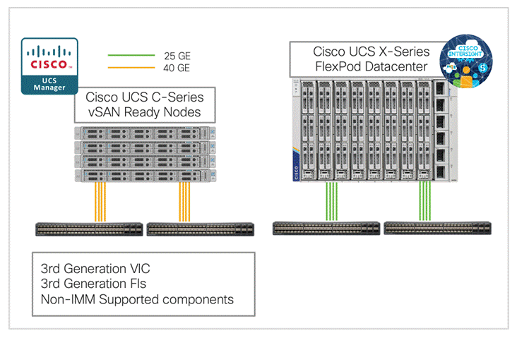
Note: The non-IMM supported Cisco UCS C-Series servers can also be connected directly to the Cisco Nexus switches and configured using CIMC. This option was not explored during the validation.
Service profile template creation using Ansible
To configure policies and service profile templates for Cisco UCS C-Series hosts configured as management domain hosts for VMware Cloud Foundation, download and execute the following ansible playbooks: https://developer.cisco.com/codeexchange/github/repo/ucs-compute-solutions/UCSM-VCF-MgmtDomain. The ansible playbooks will configure:
● Equipment Tasks to setup server ports and uplink port-channels
● Admin tasks to configure DNS, NTP, Timezone, and Organization
● LAN tasks to configure VLANs, Mgmt. and MAC address pools, various LAN policies, and vNIC templates
● Server tasks to configure UUID pools, BIOS, boot, disk, power, maintenance, and Server Profile templates
● Setup ESXi NTP server
● Setup ESXi hostname, domain, and DNS server
● Enable SSH on the ESXi hosts
● Set ESXi vSwitch0 MTU to 9000
● Set ESXi default port-group VLAN (management)
Procedure 1. Cisco UCS Service Profile Template configuration using Ansible
Step 1. Physically connect the hardware and perform the initial configuration so UCS can be accessed over network using its management IP address.
Step 2. Setup a Linux (or similar) host and install Ansible, git and required UCS and VMware packages listed in the readme file of the repository.
Step 3. Clone the repository using git.
Step 4. Update the inventory file to provide the access information for UCSM as well as ESXi host information.
Step 5. Update variables in group_vars/all.yml to match customer environment.
Step 6. Execute the Setup_UCS.yml playbook to setup all the policies and server profile template:
ansible-playbook ./Setup_UCS.yml -i inventory
Step 7. Manually derive 4 Service Profiles to deploy 4 VCF Mgmt Host servers.
Procedure 2. Prepare the ESXi hosts using Ansible
Step 1. Install ESXi on the local drives of the 4 service profiles derived in the last procedure.
Step 2. Configure the management interface of the ESXi hosts after installation.
Step 3. Execute the prepare_esxi_host.yml playbook to configure various parameters on the ESXi hosts:
ansible-playbook ./prepare_esxi_hosts.yml -i inventory
Step 4. Regenerate the self-signed certificates on all 4 ESXi hosts manually or use the regenerate_esxi_hosts_certs.yml playbook:
Manual:
/sbin/generate-certificates
/etc/init.d/hostd restart && /etc/init.d/vpxa restart
Ansible:
ansible-playbook ./regenerate_esxi_hosts_certs.yml -i inventory
Now the ESXi servers are ready for VCF cloud builder to setup the management domain.
Appendix D – References Used in Guide
Cisco Intersight: https://www.intersight.com
Cisco Intersight Managed Mode: https://www.cisco.com/c/en/us/td/docs/unified_computing/Intersight/b_Intersight_Managed_Mode_Configuration_Guide.html
Cisco Unified Computing System: http://www.cisco.com/en/US/products/ps10265/index.html
Cisco UCS 6400 Series Fabric Interconnects: https://www.cisco.com/c/en/us/products/collateral/servers-unified-computing/datasheet-c78-741116.html
Cisco Nexus 9000 Series Switches: http://www.cisco.com/c/en/us/products/switches/nexus-9000-series-switches/index.html
Cisco MDS 9132T Switches: https://www.cisco.com/c/en/us/products/collateral/storage-networking/mds-9100-series-multilayer-fabric-switches/datasheet-c78-739613.html
NetApp ONTAP: https://docs.netapp.com/ontap-9/index.jsp
NetApp Active IQ Unified Manager: https://docs.netapp.com/ocum-98/index.jsp?topic=%2Fcom.netapp.doc.onc-um-isg-lin%2FGUID-FA7D1835-F32A-4A84-BD5A-993F7EE6BBAE.html
ONTAP Storage Connector for Cisco Intersight: https://www.netapp.com/pdf.html?item=/media/25001-tr-4883.pdf
VMware Cloud Foundation 4.4 release notes: https://docs.vmware.com/en/VMware-Cloud-Foundation/4.4.1/rn/vmware-cloud-foundation-441-release-notes/index.html
VMware Cloud Foundation 4.4 Deployment Guide: https://docs.vmware.com/en/VMware-Cloud-Foundation/4.4/vcf-deploy/GUID-F2DCF1B2-4EF6-444E-80BA-8F529A6D0725.html
VMware vCenter Server: http://www.vmware.com/products/vcenter-server/overview.html
VMware vSphere: https://www.vmware.com/products/vsphere
Interoperability Matrix
Cisco UCS Hardware Compatibility Matrix: https://ucshcltool.cloudapps.cisco.com/public/
VMware and Cisco Unified Computing System: http://www.vmware.com/resources/compatibility
NetApp Interoperability Matrix Tool: http://support.netapp.com/matrix/
This glossary addresses some terms used in this document, for the purposes of aiding understanding. This is not a complete list of all multicloud terminology. Some Cisco product links are supplied here also, where considered useful for the purposes of clarity, but this is by no means intended to be a complete list of all applicable Cisco products.
| aaS/XaaS (IT capability provided as a Service) |
Some IT capability, X, provided as a service (XaaS). Some benefits are:
● The provider manages the design, implementation, deployment, upgrades, resiliency, scalability, and overall delivery of the service and the infrastructure that supports it.
● There are very low barriers to entry, so that services can be quickly adopted and dropped in response to business demand, without the penalty of inefficiently utilized CapEx.
● The service charge is an IT OpEx cost (pay-as-you-go), whereas the CapEx and the service infrastructure is the responsibility of the provider.
● Costs are commensurate to usage and hence more easily controlled with respect to business demand and outcomes.
Such services are typically implemented as “microservices,” which are accessed via REST APIs. This architectural style supports composition of service components into systems. Access to and management of aaS assets is via a web GUI and/or APIs, such that Infrastructure-as-code (IaC) techniques can be used for automation, for example, Ansible and Terraform. The provider can be any entity capable of implementing an aaS “cloud-native” architecture. The cloud-native architecture concept is well-documented and supported by open-source software and a rich ecosystem of services such as training and consultancy. The provider can be an internal IT department or any of many third-party companies using and supporting the same open-source platforms. Service access control, integrated with corporate IAM, can be mapped to specific users and business activities, enabling consistent policy controls across services, wherever they are delivered from. |
| Ansible |
An infrastructure automation tool, used to implement processes for instantiating and configuring IT service components, such as VMs on an IaaS platform. Supports the consistent execution of processes defined in YAML “playbooks” at scale, across multiple targets. Because the Ansible artefacts (playbooks) are text-based, they can be stored in a Source Code Management (SCM) system, such as GitHub. This allows for software development like processes to be applied to infrastructure automation, such as, Infrastructure-as-code (see IaC below). |
| AWS (Amazon Web Services) |
Provider of IaaS and PaaS. |
| Azure |
Microsoft IaaS and PaaS. |
| Co-located data center |
“A colocation center (CoLo)…is a type of data center where equipment, space, and bandwidth are available for rental to retail customers. Colocation facilities provide space, power, cooling, and physical security for the server, storage, and networking equipment of other firms and also connect them to a variety of telecommunications and network service providers with a minimum of cost and complexity.” |
| Containers (Docker) |
A (Docker) container is a means to create a package of code for an application and its dependencies, such that the application can run on different platforms which support the Docker environment. In the context of aaS, microservices are typically packaged within Linux containers orchestrated by Kubernetes (K8s). https://www.cisco.com/c/en/us/products/cloud-systems-management/containerplatform/index.html |
| DevOps |
The underlying principle of DevOps is that the application development and operations teams should work closely together, ideally within the context of a toolchain that automates the stages of development, test, deployment, monitoring, and issue handling. DevOps is closely aligned with IaC, continuous integration and deployment (CI/CD), and Agile software development practices. |
| Edge compute |
Edge compute is the idea that it can be more efficient to process data at the edge of a network, close to the endpoints that originate that data, or to provide virtualized access services, such as at the network edge. This could be for reasons related to low latency response, reduction of the amount of unprocessed data being transported, efficiency of resource utilization, and so on. The generic label for this is Multi-access Edge Computing (MEC), or Mobile Edge Computing for mobile networks specifically. From an application experience perspective, it is important to be able to utilize, at the edge, the same operations model, processes, and tools used for any other compute node in the system. |
| IaaS (Infrastructure as-a-Service) |
Infrastructure components provided aaS, located in data centers operated by a provider, typically accessed over the public Internet. IaaS provides a base platform for the deployment of workloads, typically with containers and Kubernetes (K8s). |
| IaC (Infrastructure as-Code) |
Given the ability to automate aaS via APIs, the implementation of the automation is typically via Python code, Ansible playbooks, and similar. These automation artefacts are programming code that define how the services are consumed. As such, they can be subject to the same code management and software development regimes as any other body of code. This means that infrastructure automation can be subject to all of the quality and consistency benefits, CI/CD, traceability, automated testing, compliance checking, and so on, that could be applied to any coding project. |
| IAM (Identity and Access Management) |
IAM is the means to control access to IT resources so that only those explicitly authorized to access given resources can do so. IAM is an essential foundation to a secure multicloud environment. |
| IBM (Cloud) |
IBM IaaS and PaaS. |
| Intersight |
Cisco Intersight™ is a Software-as-a-Service (SaaS) infrastructure lifecycle management platform that delivers simplified configuration, deployment, maintenance, and support. https://www.cisco.com/c/en/us/products/servers-unified-computing/intersight/index.html |
| GCP (Google Cloud Platform) |
Google IaaS and PaaS. |
| Kubernetes (K8s) |
Kubernetes is an open-source system for automating deployment, scaling, and management of containerized applications. |
| Microservices |
A microservices architecture is characterized by processes implementing fine-grained services, typically exposed via REST APIs and which can be composed into systems. The processes are often container-based, and the instantiation of the services often managed with Kubernetes. Microservices managed in this way are intrinsically well suited for deployment into IaaS environments, and as such, are the basis of a cloud native architecture. |
| PaaS (Platform-as-a-Service) |
PaaS is a layer of value-add services, typically for application development, deployment, monitoring, and general lifecycle management. The use of IaC with IaaS and PaaS is very closely associated with DevOps practices. |
| Private on-premises data center |
A data center infrastructure housed within an environment owned by a given enterprise is distinguished from other forms of data center, with the implication that the private data center is more secure, given that access is restricted to those authorized by the enterprise. Thus, circumstances can arise where very sensitive IT assets are only deployed in a private data center, in contrast to using public IaaS. For many intents and purposes, the underlying technology can be identical, allowing for hybrid deployments where some IT assets are privately deployed but also accessible to other assets in public IaaS. IAM, VPNs, firewalls, and similar are key technologies needed to underpin the security of such an arrangement. |
| REST API |
Representational State Transfer (REST) APIs is a generic term for APIs accessed over HTTP(S), typically transporting data encoded in JSON or XML. REST APIs have the advantage that they support distributed systems, communicating over HTTP, which is a well-understood protocol from a security management perspective. REST APIs are another element of a cloud-native applications architecture, alongside microservices. https://en.wikipedia.org/wiki/Representational_state_transfer |
| SaaS (Software-as-a-Service) |
End-user applications provided “aaS” over the public Internet, with the underlying software systems and infrastructure owned and managed by the provider. |
| SAML (Security Assertion Markup Language) |
Used in the context of Single-Sign-On (SSO) for exchanging authentication and authorization data between an identity provider, typically an IAM system, and a service provider (some form of SaaS). The SAML protocol exchanges XML documents that contain security assertions used by the aaS for access control decisions. https://en.wikipedia.org/wiki/Security_Assertion_Markup_Language |
| Terraform |
An open-source IaC software tool for cloud services, based on declarative configuration files. |
AAA—Authentication, Authorization, and Accounting
ACP—Access-Control Policy
ACI—Cisco Application Centric Infrastructure
ACK—Acknowledge or Acknowledgement
ACL—Access-Control List
AD—Microsoft Active Directory
AFI—Address Family Identifier
AMP—Cisco Advanced Malware Protection
AP—Access Point
API—Application Programming Interface
APIC— Cisco Application Policy Infrastructure Controller (ACI)
ASA—Cisco Adaptative Security Appliance
ASM—Any-Source Multicast (PIM)
ASR—Aggregation Services Router
Auto-RP—Cisco Automatic Rendezvous Point protocol (multicast)
AVC—Application Visibility and Control
BFD—Bidirectional Forwarding Detection
BGP—Border Gateway Protocol
BMS—Building Management System
BSR—Bootstrap Router (multicast)
BYOD—Bring Your Own Device
CAPWAP—Control and Provisioning of Wireless Access Points Protocol
CDP—Cisco Discovery Protocol
CEF—Cisco Express Forwarding
CMD—Cisco Meta Data
CPU—Central Processing Unit
CSR—Cloud Services Routers
CTA—Cognitive Threat Analytics
CUWN—Cisco Unified Wireless Network
CVD—Cisco Validated Design
CYOD—Choose Your Own Device
DC—Data Center
DHCP—Dynamic Host Configuration Protocol
DM—Dense-Mode (multicast)
DMVPN—Dynamic Multipoint Virtual Private Network
DMZ—Demilitarized Zone (firewall/networking construct)
DNA—Cisco Digital Network Architecture
DNS—Domain Name System
DORA—Discover, Offer, Request, ACK (DHCP Process)
DWDM—Dense Wavelength Division Multiplexing
ECMP—Equal Cost Multi Path
EID—Endpoint Identifier
EIGRP—Enhanced Interior Gateway Routing Protocol
EMI—Electromagnetic Interference
ETR—Egress Tunnel Router (LISP)
EVPN—Ethernet Virtual Private Network (BGP EVPN with VXLAN data plane)
FHR—First-Hop Router (multicast)
FHRP—First-Hop Redundancy Protocol
FMC—Cisco Firepower Management Center
FTD—Cisco Firepower Threat Defense
GBAC—Group-Based Access Control
GbE—Gigabit Ethernet
Gbit/s—Gigabits Per Second (interface/port speed reference)
GRE—Generic Routing Encapsulation
GRT—Global Routing Table
HA—High-Availability
HQ—Headquarters
HSRP—Cisco Hot-Standby Routing Protocol
HTDB—Host-tracking Database (SD-Access control plane node construct)
IBNS—Identity-Based Networking Services (IBNS 2.0 is the current version)
ICMP— Internet Control Message Protocol
IDF—Intermediate Distribution Frame; essentially a wiring closet.
IEEE—Institute of Electrical and Electronics Engineers
IETF—Internet Engineering Task Force
IGP—Interior Gateway Protocol
IID—Instance-ID (LISP)
IOE—Internet of Everything
IoT—Internet of Things
IP—Internet Protocol
IPAM—IP Address Management
IPS—Intrusion Prevention System
IPSec—Internet Protocol Security
ISE—Cisco Identity Services Engine
ISR—Integrated Services Router
IS-IS—Intermediate System to Intermediate System routing protocol
ITR—Ingress Tunnel Router (LISP)
LACP—Link Aggregation Control Protocol
LAG—Link Aggregation Group
LAN—Local Area Network
L2 VNI—Layer 2 Virtual Network Identifier; as used in SD-Access Fabric, a VLAN.
L3 VNI— Layer 3 Virtual Network Identifier; as used in SD-Access Fabric, a VRF.
LHR—Last-Hop Router (multicast)
LISP—Location Identifier Separation Protocol
MAC—Media Access Control Address (OSI Layer 2 Address)
MAN—Metro Area Network
MEC—Multichassis EtherChannel, sometimes referenced as MCEC
MDF—Main Distribution Frame; essentially the central wiring point of the network.
MnT—Monitoring and Troubleshooting Node (Cisco ISE persona)
MOH—Music on Hold
MPLS—Multiprotocol Label Switching
MR—Map-resolver (LISP)
MS—Map-server (LISP)
MSDP—Multicast Source Discovery Protocol (multicast)
MTU—Maximum Transmission Unit
NAC—Network Access Control
NAD—Network Access Device
NAT—Network Address Translation
NBAR—Cisco Network-Based Application Recognition (NBAR2 is the current version).
NFV—Network Functions Virtualization
NSF—Non-Stop Forwarding
OSI—Open Systems Interconnection model
OSPF—Open Shortest Path First routing protocol
OT—Operational Technology
PAgP—Port Aggregation Protocol
PAN—Primary Administration Node (Cisco ISE persona)
PCI DSS—Payment Card Industry Data Security Standard
PD—Powered Devices (PoE)
PETR—Proxy-Egress Tunnel Router (LISP)
PIM—Protocol-Independent Multicast
PITR—Proxy-Ingress Tunnel Router (LISP)
PnP—Plug-n-Play
PoE—Power over Ethernet (Generic term, may also refer to IEEE 802.3af, 15.4W at PSE)
PoE+—Power over Ethernet Plus (IEEE 802.3at, 30W at PSE)
PSE—Power Sourcing Equipment (PoE)
PSN—Policy Service Node (Cisco ISE persona)
pxGrid—Platform Exchange Grid (Cisco ISE persona and publisher/subscriber service)
PxTR—Proxy-Tunnel Router (LISP – device operating as both a PETR and PITR)
QoS—Quality of Service
RADIUS—Remote Authentication Dial-In User Service
REST—Representational State Transfer
RFC—Request for Comments Document (IETF)
RIB—Routing Information Base
RLOC—Routing Locator (LISP)
RP—Rendezvous Point (multicast)
RP—Redundancy Port (WLC)
RP—Route Processer
RPF—Reverse Path Forwarding
RR—Route Reflector (BGP)
RTT—Round-Trip Time
SA—Source Active (multicast)
SAFI—Subsequent Address Family Identifiers (BGP)
SD—Software-Defined
SDA—Cisco Software Defined-Access
SDN—Software-Defined Networking
SFP—Small Form-Factor Pluggable (1 GbE transceiver)
SFP+— Small Form-Factor Pluggable (10 GbE transceiver)
SGACL—Security-Group ACL
SGT—Scalable Group Tag, sometimes reference as Security Group Tag
SM—Spare-mode (multicast)
SNMP—Simple Network Management Protocol
SSID—Service Set Identifier (wireless)
SSM—Source-Specific Multicast (PIM)
SSO—Stateful Switchover
STP—Spanning-tree protocol
SVI—Switched Virtual Interface
SVL—Cisco StackWise Virtual
SWIM—Software Image Management
SXP—Scalable Group Tag Exchange Protocol
Syslog—System Logging Protocol
TACACS+—Terminal Access Controller Access-Control System Plus
TCP—Transmission Control Protocol (OSI Layer 4)
UCS— Cisco Unified Computing System
UDP—User Datagram Protocol (OSI Layer 4)
UPoE—Cisco Universal Power Over Ethernet (60W at PSE)
UPoE+— Cisco Universal Power Over Ethernet Plus (90W at PSE)
URL—Uniform Resource Locator
VCF—VMware Cloud Foundation
vHBA—virtual Host Bus Adapter
VLAN—Virtual Local Area Network
VM—Virtual Machine
VN—Virtual Network, analogous to a VRF in SD-Access
VNI—Virtual Network Identifier (VXLAN)
vNIC—virtual Network Interface Card
vPC—virtual Port Channel (Cisco Nexus)
VPLS—Virtual Private LAN Service
VPN—Virtual Private Network
VPNv4—BGP address family that consists of a Route-Distinguisher (RD) prepended to an IPv4 prefix
VPWS—Virtual Private Wire Service
VRF—Virtual Routing and Forwarding
VSL—Virtual Switch Link (Cisco VSS component)
VSS—Cisco Virtual Switching System
VXLAN—Virtual Extensible LAN
WAN—Wide-Area Network
WLAN—Wireless Local Area Network (generally synonymous with IEEE 802.11-based networks)
WoL—Wake-on-LAN
xTR—Tunnel Router (LISP – device operating as both an ETR and ITR)
Appendix G – Recommended for You
FlexPod Datacenter with Cisco UCS X-Series Design Guide:
FlexPod Datacenter with UCS X-Series Design Guide:
https://www.cisco.com/c/en/us/td/docs/unified_computing/ucs/UCS_CVDs/flexpod_xseries_vmware_7u2.html
FlexPod Datacenter with End-to-End 100G Design Guide:
For comments and suggestions about this guide and related guides, join the discussion on Cisco Community at https://cs.co/en-cvds.
CVD Program
ALL DESIGNS, SPECIFICATIONS, STATEMENTS, INFORMATION, AND RECOMMENDATIONS (COLLECTIVELY, "DE-SIGNS") IN THIS MANUAL ARE PRESENTED "AS IS," WITH ALL FAULTS. CISCO AND ITS SUPPLIERS DISCLAIM ALL WAR-RANTIES, INCLUDING, WITHOUT LIMITATION, THE WARRANTY OF MERCHANTABILITY, FITNESS FOR A PARTICULAR PURPOSE AND NONINFRINGEMENT OR ARISING FROM A COURSE OF DEALING, USAGE, OR TRADE PRACTICE. IN NO EVENT SHALL CISCO OR ITS SUPPLIERS BE LIABLE FOR ANY INDIRECT, SPECIAL, CONSEQUENTIAL, OR INCIDENTAL DAMAGES, INCLUDING, WITHOUT LIMITATION, LOST PROFITS OR LOSS OR DAMAGE TO DATA ARISING OUT OF THE USE OR INABILITY TO USE THE DESIGNS, EVEN IF CISCO OR ITS SUPPLIERS HAVE BEEN ADVISED OF THE POSSIBILITY OF SUCH DAMAGES.
THE DESIGNS ARE SUBJECT TO CHANGE WITHOUT NOTICE. USERS ARE SOLELY RESPONSIBLE FOR THEIR APPLICA-TION OF THE DESIGNS. THE DESIGNS DO NOT CONSTITUTE THE TECHNICAL OR OTHER PROFESSIONAL ADVICE OF CISCO, ITS SUPPLIERS OR PARTNERS. USERS SHOULD CONSULT THEIR OWN TECHNICAL ADVISORS BEFORE IMPLE-MENTING THE DESIGNS. RESULTS MAY VARY DEPENDING ON FACTORS NOT TESTED BY CISCO.
CCDE, CCENT, Cisco Eos, Cisco Lumin, Cisco Nexus, Cisco StadiumVision, Cisco TelePresence, Cisco WebEx, the Cisco logo, DCE, and Welcome to the Human Network are trademarks; Changing the Way We Work, Live, Play, and Learn and Cisco Store are service marks; and Access Registrar, Aironet, AsyncOS, Bringing the Meeting To You, Catalyst, CCDA, CCDP, CCIE, CCIP, CCNA, CCNP, CCSP, CCVP, Cisco, the Cisco Certified Internetwork Expert logo, Cisco IOS, Cisco Press, Cisco Systems, Cisco Systems Capital, the Cisco Systems logo, Cisco Unified Computing System (Cisco UCS), Cisco UCS B-Series Blade Servers, Cisco UCS C-Series Rack Servers, Cisco UCS S-Series Storage Servers, Cisco UCS Manager, Cisco UCS Management Software, Cisco Unified Fabric, Cisco Application Centric Infrastructure, Cisco Nexus 9000 Series, Cisco Nexus 7000 Series. Cisco Prime Data Center Network Manager, Cisco NX-OS Software, Cis-co MDS Series, Cisco Unity, Collaboration Without Limitation, EtherFast, EtherSwitch, Event Center, Fast Step, Follow Me Browsing, FormShare, GigaDrive, HomeLink, Internet Quotient, IOS, iPhone, iQuick Study, LightStream, Linksys, MediaTone, MeetingPlace, MeetingPlace Chime Sound, MGX, Networkers, Networking Academy, Network Registrar, PCNow, PIX, PowerPanels, ProConnect, ScriptShare, SenderBase, SMARTnet, Spectrum Expert, StackWise, The Fastest Way to Increase Your Internet Quotient, TransPath, WebEx, and the WebEx logo are registered trade-marks of Cisco Systems, Inc. and/or its affiliates in the United States and certain other countries. (LDW_P1)
All other trademarks mentioned in this document or website are the property of their respective owners. The use of the word partner does not imply a partnership relationship between Cisco and any other company. (0809R)