FlashStack for SAP HANA TDI with Cisco UCS M6 X-Series Design Guide
Available Languages
Bias-Free Language
The documentation set for this product strives to use bias-free language. For the purposes of this documentation set, bias-free is defined as language that does not imply discrimination based on age, disability, gender, racial identity, ethnic identity, sexual orientation, socioeconomic status, and intersectionality. Exceptions may be present in the documentation due to language that is hardcoded in the user interfaces of the product software, language used based on RFP documentation, or language that is used by a referenced third-party product. Learn more about how Cisco is using Inclusive Language.
- US/Canada 800-553-2447
- Worldwide Support Phone Numbers
- All Tools
 Feedback
 Feedback

In partnership with:

About the Cisco Validated Design Program
The Cisco Validated Design (CVD) program consists of systems and solutions designed, tested, and documented to facilitate faster, more reliable, and more predictable customer deployments. For more information, go to: http://www.cisco.com/go/designzone.
FlashStack for SAP HANA TDI is a validated, converged infrastructure solution developed jointly by Cisco and Pure Storage. The solution offers a predesigned data center architecture that incorporates the Cisco Unified Computing System (Cisco UCS) X-Series modular platform, Cisco UCS B-Series, and Cisco UCS C-Series, the all-flash enterprise storage FlashArray//X, and networking to reduce IT risk by validating the architecture and helping ensure compatibility among the components. FlashStack is a great choice for SAP ERP, SAP HANA, virtualization, and other enterprise applications.
This document explains the design details of incorporating the Cisco UCS X-Series modular platform into the FlashStack for SAP HANA TDI solution and its ability to manage and orchestrate FlashStack components from the cloud using Cisco Intersight. Some of the most important advantages of integrating Cisco UCS X-Series into the FlashStack infrastructure include:
● Simpler and programmable infrastructure: Infrastructure as code delivered through an open application programming interface (API).
● Power and cooling innovations: Higher-power headroom and lower energy loss because of a 54V DC power delivery to the chassis.
● Better airflow: Midplane free design with fewer barriers, thus lower impedance.
● Fabric innovations: PCIe/Compute Express Link (CXL) topology for heterogeneous compute and memory composability.
● Innovative cloud operations: Continuous feature delivery and infrastructure management.
● Built for investment protections: Design-ready for future technologies such as liquid-cooling and high-wattage CPUs; CXL ready.
In addition to the compute-specific hardware and software innovations, integration of the Cisco Intersight cloud platform with VMware vCenter Server and FlashArray’s Purity operating environment delivers monitoring, orchestration, and workload optimization capabilities for different layers (virtualization and storage) of the FlashStack solution.
If you are interested in understanding the FlashStack design and deployment details, including configuration of various elements of design and associated best practices, please refer to Cisco Validated Designs for FlashStack here: https://www.cisco.com/c/en/us/solutions/design-zone/data-center-design-guides/data-center-design-guides-all.html#FlashStack.
This chapter is organized as follows:
● Audience
The Cisco UCS X-Series is a new modular compute system configured and managed from the cloud. It is designed to meet the needs of modern applications and improve operational efficiency, agility, and scale through an adaptable, future-ready, modular design. The Cisco Intersight platform software-as-a-service (SaaS) infrastructure lifecycle management platform delivers simplified configuration, deployment, maintenance, and support.
SAP HANA in-memory database handles transactional and analytical workloads with any data type – on a single data copy. It breaks down the transactional and analytical silos in organizations, for quick decision-making, on premise and in the cloud. SAP HANA offers a multi-engine, query-processing environment that supports relational data (with both row- and column-oriented physical representations in a hybrid engine) as well as graph and text processing for semi-structured and unstructured data management within the same system. The SAP HANA Tailored Datacenter Integration (TDI) solution offers a more open and flexible way for the integration of SAP HANA into the data center with benefits like the virtualization of the SAP HANA platform or a flexible combination of multiple SAP HANA production systems on the fully certified, converged infrastructure.
Powered by the Cisco Intersight cloud operations platform, the Cisco UCS X-Series enables the next-generation cloud-operated FlashStack infrastructure that not only simplifies the datacenter management but also allows the infrastructure to adapt to unpredictable needs of the modern applications as well as traditional workloads. With the Cisco Intersight platform, you get all the benefits of SaaS delivery and the full lifecycle management of Cisco Intersight connected, distributed servers and integrated Pure Storage FlashArrays across data centers, remote sites, branch offices, and edge environments.
The intended audience for this document includes, but is not limited to, IT and SAP solution architects, sales engineers, field consultants, professional services, IT managers, IT engineers, partners, and customers who are interested in learning about and deploying the FlashStack solution for SAP and SAP HANA use cases, such as target storage for backups, SAP HANA system replication, SAP HANA scale out file services with NFS or mixed configurations with Linux bare metal and VMware ESXi installations.
This document builds on top of the design whitepaper FlashStack with Cisco UCS X-Series and Cisco Intersight (https://www.cisco.com/c/en/us/products/collateral/servers-unified-computing/ucs-x-series-modular-system/flashstack-with-ucs-x-and-intersight.pdf) and extend the design with Cisco UCS B-Series attached to the same Cisco fabric interconnects operated in Cisco Intersight managed mode. It incorporates design considerations and requirements for FlashStack Virtual Server Infrastructure (VSI) and discuss best practices for a successful installation and operation of a virtualized SAP HANA on FlashStack. It also highlights the design and product requirements for integrating virtualization and the storage system with Cisco Intersight to deliver a true cloud-based integrated approach for infrastructure management.
It assumes that the reader has a basic knowledge of VMware vSphere concepts and features, SAP HANA, and all related SAP products and technologies.
The following design elements distinguish this version of FlashStack for SAP HANA TDI from previous models:
● Integration of Cisco UCS X-Series into FlashStack for SAP HANA TDI.
● Management of Cisco UCS X-Series and B-Series from the cloud using Cisco Intersight.
● Integration of the Pure Storage FlashArray//X into Cisco Intersight for monitoring and orchestration.
● Integration of the VMware vCenter into Cisco Intersight for interaction with, monitoring, and orchestration of the virtual environment.
● Support for VMware vSphere 7.0 U3c.
Like all other FlashStack solution designs, FlashStack for SAP HANA TDI with Cisco UCS X-Series and Cisco UCS B-Series operated in Cisco Intersight managed mode is configurable according to demand and usage. Customers can purchase exactly the infrastructure they need for their current SAP HANA and SAP application requirements and then can scale up by adding more resources to the FlashStack solution or scale out by adding more FlashStack instances. By moving the management from the fabric interconnects into the cloud, the solution can respond to speed and scale of customer deployments with a constant stream of new capabilities from the Cisco Intersight SaaS model at cloud scale.
Many enterprises today are seeking pre-engineered solutions that standardize data center infrastructure, offering organizations operational efficiency, agility, and scale to address cloud and bi-modal IT and their business. Their challenge is complexity, diverse application support, efficiency, and risk. FlashStack addresses all the challenges with these features:
● Stateless architecture, providing the capability to expand and adapt to new business requirements
● Reduced complexity, automatable infrastructure, and easily deployed resources
● Robust components capable of supporting high-performance and high bandwidth for virtualized and non-virtualized applications
● Efficiency through optimization of network bandwidth and inline storage compression with deduplication
● Risk reduction at each level of the design with resiliency built into each touch point
● Simplified cloud-based management of the solution components
● Highly available and scalable platform with flexible architecture that support various deployment models
● Cisco solution support for critical infrastructure with single point of support contact
● Purity Protect for SAP with full business continuity with Purity ActiveCluster; seamless management, backup, restore and recovery across dispersed systems with almost zero performance penalty
● Evergreen Storage Services provides cloud-like consumption models for on-premises storage
● AppDynamics SAP Application Performance Monitoring
This chapter is organized as follows:
● Cisco UCS Fabric Interconnects
● Cisco Unified Computing System X-Series
● Cisco Nexus 9300-FX Series Switches
● Cisco MDS 9100 Series SAN Switches
● Cisco Nexus Dashboard Fabric Controller
● SAP Application Monitoring with AppDynamics
● VMware vSphere 7.0 Update 3c
● Cisco Intersight Assist Device Connector for VMware vCenter and Pure Storage FlashArray//X
● Red Hat Ansible Automation Platform
● Red Hat Enterprise Linux for SAP Solutions
● SUSE Linux Enterprise Server for SAP Applications
Cisco and Pure Storage have partnered to deliver several Cisco Validated Designs, which use best-in-class storage, server, and network components to serve as foundation for SAP workloads, enabling efficient and certified architectural designs that you can deploy quickly and confidently.
In general, the FlashStack architecture builds on the following infrastructure components for compute, storage, and network:
● Cisco Unified Computing System (Cisco UCS)
● Cisco Nexus switches
● Cisco MDS 9000 multilayer SAN switches
● Pure Storage FlashArray//X
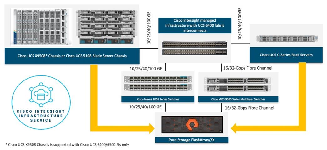
All the FlashStack components are integrated, so customers can deploy the solution quickly and economically while eliminating many of the risks associated with researching, designing, building, and deploying similar solutions from the foundation. One of the main benefits of FlashStack is its ability to maintain consistency at scale. Each of the component families shown in Figure 1 (Cisco UCS, Cisco Nexus, Cisco MDS, and Pure Storage FlashArray//X) offers platform and resource options to scale up or scale out the infrastructure while supporting the same features and functions.
The FlashStack for SAP HANA solution with Cisco UCS X-Series and Cisco UCS B-Series uses the following hardware components:
● Cisco UCS X9508 chassis with any number of Cisco UCS X210c M6 compute nodes.
● Cisco UCS 5108 chassis with any number of Cisco UCS B200 M6 or 4-socket Cisco UCS B480 M5 blade servers.
● Cisco fourth-generation 6454 fabric interconnects to support 25- and 100-GE connectivity from various components.
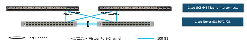
● High-speed Cisco NXOS-based Nexus 93180YC-FX3 switching design to support up to 100-GE connectivity.
● Cisco MDS 9148T SAN switch to support consistent 16- or 32-Gbps Fibre Channel port performance.
● Pure Storage FlashArray//X50 R3 with high-speed Ethernet and Fibre Channel connectivity.
Software release requirements depend on the CPU architecture, individual SAP HANA hard- and software certifications, and whether hosts are running SAP or other enterprise applications beside SAP HANA. To overcome software release dependencies of the solution the software components consist of:
● Cisco Intersight to deploy, maintain, and support the FlashStack components.
● Cisco Intersight Assist virtual appliance to help connect the Pure Storage FlashArray and VMware vCenter with Cisco Intersight.
● Purity//FA 6.3.7 and later.
● VMware vSphere 7.0 U3c and later.
● VMware vCenter 7.0 and later to set up and manage the virtual infrastructure and integration into Cisco Intersight.
● Red Hat Enterprise Linux for SAP Solutions 8.2 and later.
● SUSE Linux Enterprise System for SAP Applications 15 SP2 and later.
● SAP HANA 1.0 SPS 12 Revision 122.19; SAP HANA 2.0 recommended.
| Tech tip |
| The solution consists of VMware certified systems as listed on the VMware hardware compatibility list (HCL) and SAP HANA supported server and storage systems, as listed on the certified and supported SAP HANA hardware directory. |
Cisco UCS Fabric Interconnects
The Cisco UCS Fabric Interconnect (FI) is a core part of the Cisco Unified Computing System, providing both network connectivity and management capabilities for the system. Depending on the model chosen, the Cisco UCS Fabric Interconnect offers line-rate, low-latency, lossless 10 Gigabit, 25 Gigabit, 40 Gigabit, or 100 Gigabit Ethernet, Fibre Channel over Ethernet (FCoE) and 16 or 32 Gigabit Fibre Channel connectivity. Cisco UCS Fabric Interconnects provide the management and communication backbone for the Cisco UCS X-Series, Cisco UCS C-Series, Cisco UCS B-Series Blade Servers, and Cisco UCS 5100 Series Blade Server Chassis. All servers and chassis, and therefore all blades, attached to the Cisco UCS Fabric Interconnects become part of a single, highly available management domain. In addition, by supporting unified fabrics, the Cisco UCS Fabric Interconnects provide both the LAN and SAN connectivity for all servers within its domain.
The current design uses the 54-port Cisco UCS 6454 fabric interconnect. This one-rack-unit (1RU) device includes twenty-eight 10-/25-GE ports, four 1-/10-/25-GE ports, six 40-/100-GE uplink ports, and sixteen unified ports that can support 10-/25-GE or 8-/16-/32-Gbps Fibre Channel, depending on the Small Form-Factor Pluggable (SFP) adapter.

Other Cisco FI models which support Intersight managed mode are the Cisco UCS 64108 and 6536 fabric interconnects.
Note: The Cisco UCS X-Series require the Cisco Fabric Interconnects to be configured in Intersight managed mode. This replaces the local Cisco Manager (UCSM) management with Cisco Intersight cloud (or appliance)-based management.
Cisco UCS unified fabric: I/O consolidation
The Cisco UCS 6454 Fabric Interconnect is built to consolidate LAN and SAN traffic onto a single unified fabric, saving on Capital Expenditures (CapEx) and Operating Expenses (OpEx) associated with multiple parallel networks, different types of adapter cards, switching infrastructure, and cabling within racks. The unified ports allow ports in the fabric interconnect to support direct connections from Cisco UCS to existing native Fibre Channel SANs. The capability to connect to a native Fibre Channel protects existing storage-system investments while dramatically simplifying in-rack cabling.
Cisco UCS Fabric Interconnects supports I/O consolidation with end-to-end network virtualization, visibility, and QoS guarantees for the following LAN and SAN traffic:
● FC SAN, IP Storage (iSCSI, NFS), NVMeoF (NVMe/FC, NVMe/TCP, NVMe over ROCEv2)
● Server management and LAN traffic
The I/O consolidation under the Cisco UCS 6454 fabric interconnect along with the stateless policy-driven architecture of Cisco UCS and the hardware acceleration of the Cisco UCS Virtual Interface cards provides great simplicity, flexibility, resiliency, performance, and TCO savings for the customer’s compute infrastructure.
Cisco Unified Computing System X-Series
The Cisco UCS X-Series modular system is designed to take the current generation of the Cisco UCS platform to the next level with its design that will support future innovations and management in the cloud (Figure 3). Decoupling and moving platform management to the cloud allows the Cisco UCS platform to respond to your feature and scalability requirements much faster and more efficiently. Cisco UCS X-Series state-of-the-art hardware simplifies the datacenter design by providing flexible server options. A single server type that supports a broader range of workloads results in fewer different datacenter products to manage and maintain. The Cisco Intersight cloud management platform manages the Cisco UCS X-Series as well as integrates with third-party devices and software. These devices include VMware vCenter and Pure Storage FlashArray//X to provide visibility, optimization, and orchestration from a single platform, thereby enhancing agility and deployment consistency.
The following sections address various components of the Cisco UCS X-Series.
Cisco UCSX-9508 Chassis
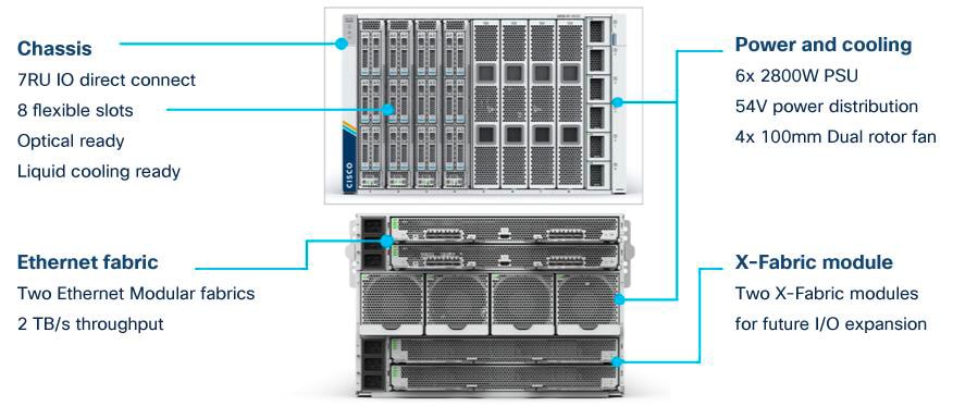
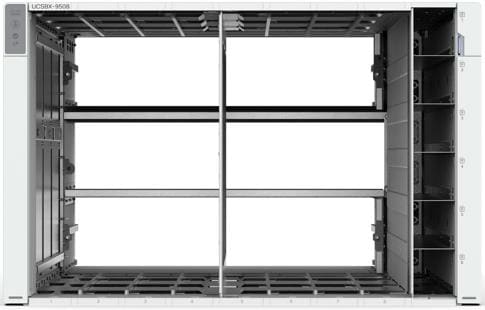
The Cisco UCS X-Series chassis is engineered to be adaptable and flexible. As seen in Figure 4, the UCSX-9508 chassis has only a power-distribution midplane. This innovative design provides fewer obstructions for better airflow. For I/O connectivity, vertically oriented compute nodes intersect with horizontally oriented fabric modules, allowing the chassis to support future fabric innovations. Improved airflow through the chassis enables support for higher power components, and more space allows for future thermal solutions (such as liquid cooling) without limitations. The Cisco UCS X-Series chassis features several enhancements compared to the Cisco UCS chassis, and the Intelligent Fabric Modules (IFMs) take the role of the I/O modules (IOMs). Specialized GPU nodes and storage nodes offer a new possibility for growth and technology expansion leveraging the high-performance compute express link (CXL) bus.
The Cisco UCSX-9508 7-rack-unit (7RU) chassis has eight flexible slots. These slots can house a combination of compute nodes and a pool of future I/O resources that may include GPU accelerators or nonvolatile memory (NVM). At the top rear of the chassis are two intelligent fabric modules (IFM) that connect the chassis to upstream Cisco UCS 6400 Series fabric interconnects. At the bottom rear of the chassis are slots ready to house future X-Fabric modules that can flexibly connect the compute nodes with I/O devices. Six 2800W power supply units (PSUs) provide 54V DC power to the chassis with N, N+1, and N+N redundancy. A higher voltage allows efficient power delivery with less copper and reduced power loss. Efficient, 100-mm, dual counter-rotating fans deliver industry-leading airflow and power efficiency, and optimized thermal algorithms enable different cooling modes to best support your environment.
Cisco UCSX 9108-25G Intelligent Fabric Modules
For the Cisco UCSX-9508 chassis, a pair of Cisco UCS 9108-25G IFMs provide network connectivity. Like the fabric extenders used in the Cisco UCS 5108 Blade Server chassis, these modules carry all network traffic to a pair of Cisco UCS 6400 Series fabric interconnects. IFM also hosts a chassis management controller (CMC). High-speed PCIe-based fabric topology provides extreme flexibility compared to a combination of serial-attached SCSI (SAS), Serial Advanced Technology Attachment (SATA), or Fibre Channel. In contrast to systems with fixed networking components, the design of the Cisco UCSX-9508 enables easy upgrades to new networking technologies as they emerge, making it straightforward to accommodate new network speeds or technologies in the future.

Each IFM supports eight 25-Gb uplink ports for connecting the Cisco UCSX-9508 chassis to the fabric interconnects and 32 25-Gb server ports for the eight compute nodes. The IFM server ports can provide up to 200 Gbps of unified fabric connectivity per compute node across the two IFMs. The uplink ports connect the chassis to a Cisco UCS fabric interconnect to provide up to 400 Gbps connectivity across the two IFMs. The unified fabric carries management, virtual-machine, and Fibre Channel over Ethernet (FCoE) traffic to the fabric interconnects, where management traffic is routed to the Cisco Intersight cloud operations platform. FCoE traffic is forwarded to the native Fibre Channel interfaces through unified ports on the fabric interconnect (to Cisco MDS switches), and virtual-machine Ethernet traffic is forwarded upstream to the data center network (by Cisco Nexus switches).
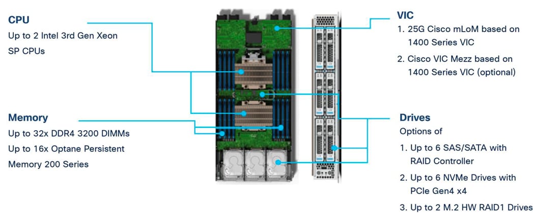
Cisco UCS X210c M6 Compute Node
The Cisco UCS X210c M6 Compute Node is the first computing device to integrate into the Cisco UCS X-Series Modular System. Up to eight compute nodes can reside in the Cisco UCS X9508 Chassis, offering one of the highest densities of compute, IO, and storage per rack unit in the industry.
It provides the following features:
● CPU: One or two third-generation Intel Xeon scalable processors (Ice Lake) with up to 40 cores per processor and a 1.5-MB Level 3 cache per core.
● Memory: Install up to thirty-two 256-GB DDR4-3200 (DIMMs) for a maximum of 8 TB of main memory. You can configure the compute node for up to sixteen 512-GB Intel Optane persistent memory DIMMs for a maximum of 12 TB of memory.
● Disk storage: Configure up to 6 SAS or SATA drives with an internal (RAID) controller or up to 6 nonvolatile memory express (NVMe) drives. You can add 2 M.2 memory cards to the compute node with RAID 1 mirroring.
● Virtual interface card: Install up to 2 virtual interface cards, including a Cisco UCS Virtual Interface Card (VIC) modular LOM card (mLOM) 14425 or mLOM 15231, enabling up to 50/100 Gbps of unified fabric connectivity to each of the IFMs for 100Gpbs connectivity per server and optionally a mezzanine Cisco VIC 14825 in a compute node.
● Security: Support for an optional trusted platform module (TPM). Additional security features include a secure boot field-programmable gate array (FPGA) and ACT2 anti-counterfeit provisions.
For SAP HANA production system, the maximum allowed memory configuration is 2 TB of main memory for SAP BW/4HANA or BW on HANA and 4 TB of main memory for SAP S/4HANA or Suite on HANA. As of SAP HANA 2.0 SPS 04 the memory limit can be extended in combination with Intel Optane persistent memory DIMMs operated in AppDirect mode.
The maximum host capacity of Intel Optane persistent memory DIMMs enabled in VMware vSphere 7.0 is up to 8 TB – both in AppDirect and memory mode. VMware vSphere usage of Intel Optane persistent memory in memory mode can offer increased memory capacity but changes the operation mode from persistent to volatile with DRAM caching.
Cisco UCS Virtual Interface Cards (VICs)
Cisco UCS X210c M6 compute nodes support the fourth generation Cisco UCS VIC 14425 or 14825 cards as well as the fifth generation Cisco UCS VIC 15231 card for end-to-end 100G network connectivity.
Cisco UCS VIC 14425
Cisco UCS VIC 14425 fits the mLOM slot in the Cisco X210c compute node and enables up to 50 Gbps of unified fabric connectivity to each of the chassis IFMs for a total of 100 Gbps of connectivity per server (Figure 7). Cisco VIC 14425 connectivity to the IFM and up to the fabric interconnects is delivered through four 25-Gbps connections that are configured automatically as two 50-Gbps port channels. Cisco VIC 14425 supports 256 virtual interfaces (both Fibre Channel and Ethernet) along with the latest networking innovations such as NVMe over Fabric over Remote Direct Memory Access (RDMA), RDMA over Converged Infrastructure (RoCEv2), Virtual Extensible VLAN gateway/Network Virtualization using Generic Routing Encapsulation (VxLAN/NVGRE) offload, and so on.
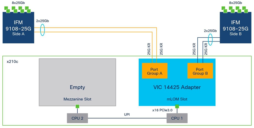
The connections between the fourth-generation Cisco UCS VIC (Cisco UCS VIC 1440) in the Cisco UCS B200 blades and the I/O modules in the Cisco UCS VIC 5108 chassis comprise multiple 10-Gbps KR lanes. The same connections between Cisco VIC 14425 and IFM in the Cisco UCS X-Series comprise multiple 25-Gbps KR lanes, resulting in 2.5 times better connectivity in Cisco UCS X210c M6 compute nodes.
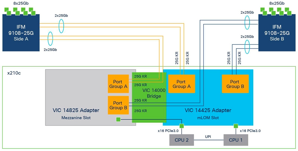
Cisco UCS VIC 14825
The optional Cisco UCS VIC 14825 fits the mezzanine slot on the server. A bridge card (part number UCSX-V4-BRIDGE) extends the two 50 Gbps of network connections of this VIC up to the mLOM slot and out through the IFM connectors, bringing the total bandwidth to 100 Gbps per fabric for a total bandwidth of 200 Gbps per server.
Cisco Intersight is a lifecycle management platform for your infrastructure, regardless of where it resides. In your enterprise data center, at the edge, in remote and branch offices, at retail and industrial sites—all these locations present unique management challenges and have typically required separate tools. Cisco Intersight Software as a Service (SaaS) unifies and simplifies your experience of the Cisco Unified Computing System (Cisco UCS) and Cisco HyperFlex systems.
The modular Cisco Intersight platform design allows you to adopt services based on your individual requirements. It significantly simplifies IT operations by bridging applications with infrastructure, providing visibility and management from bare-metal servers and hypervisors to serverless applications, thereby reducing costs and mitigating risks.
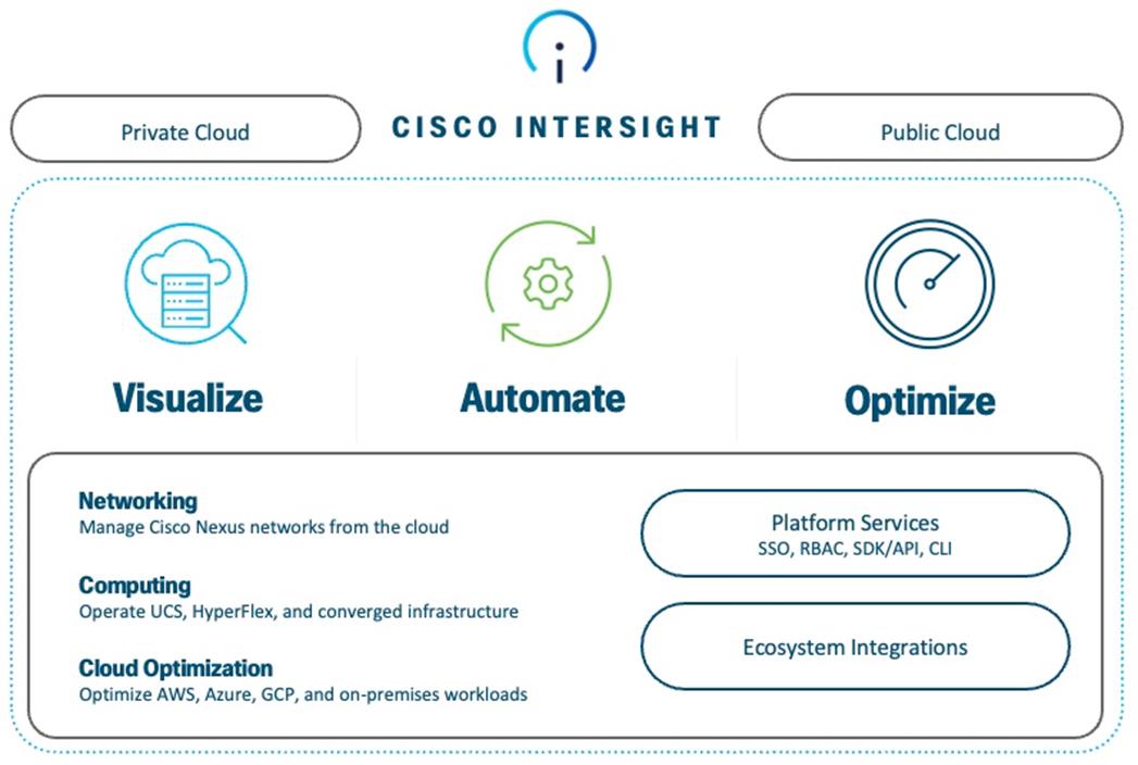
The unified Open API design of Cisco Intersight allows the natively integration with third-party platforms and tools. The main benefits of Cisco Intersight infrastructure services are as follows:
● Simplify daily operations by automating many daily manual tasks.
● Combine the convenience of a SaaS platform with the capability to connect from anywhere and manage infrastructure through a browser or mobile app.
● Stay ahead of problems and accelerate trouble resolution through advanced support capabilities.
● Gain global visibility of infrastructure health and status along with advanced management and support capabilities.
Cisco Intersight Virtual Appliance and Private Virtual Appliance
In addition to the SaaS deployment model running on intersight.com, on-premises options can be purchased separately. The Cisco Intersight Virtual Appliance and Cisco Intersight Private Virtual Appliance are available for organizations that have additional data locality or security requirements for managing systems. The Cisco Intersight Virtual Appliance delivers the management features of the Cisco Intersight platform in an easy-to-deploy VMware Open Virtualization Appliance (OVA) or Microsoft Hyper-V Server virtual machine that allows you to control the system details that leave your premises. The Cisco Intersight Private Virtual Appliance is provided in a form factor specifically designed for users who operate in disconnected (air gap) environments. The Private Virtual Appliance requires no connection to public networks or back to Cisco to operate.
Cisco Intersight Assist
Cisco Intersight Assist helps customers add endpoint devices to Cisco Intersight. A data center could have multiple devices that do not have a direct path to Intersight and do not have an embedded Intersight Device Connector. Intersight Assist communicates with the target’s native APIs and serves as the communication bridge to and from Intersight. In FlashStack, Cisco Intersight Assist enables the communication of VMware vCenter and the Pure Storage FlashArray//X to Cisco Intersight.
Cisco Intersight Assist is available within the Cisco Intersight Virtual Appliance, distributed as a deployable virtual machine and contained within an Open Virtual Appliance (OVA) file format. More details about the Cisco Intersight Assist VM deployment configuration is covered in later sections.
Cisco Intersight license requirements
Cisco Intersight offers services that allow you to manage, automate, optimize, and support your physical and virtual infrastructure. The infrastructure and cloud orchestrator service uses a subscription-based license with multiple tiers. Customers can purchase a subscription duration of one, three, or five years and choose the required Cisco UCS server volume tier for the selected subscription duration. Each Cisco endpoint automatically includes a limited number of Intersight features when you access the Cisco Intersight portal and claim a device.
Customers can purchase any of the following higher-tier Cisco Intersight licenses using the Cisco ordering tool:
● Cisco Intersight Infrastructure Service - Essentials: Essentials includes Intersight functionality for Cisco UCS and Hyperflex servers along with additional features such as policy-based configuration with server profiles, firmware management, and evaluation of compatibility with the Cisco hardware compatibility list (HCL).
● Cisco Intersight Infrastructure Service - Advantage: Advantage offers all the features and functions of the Essentials tier. It includes storage widgets and cross-domain inventory correlation across compute, storage, and virtual environments (VMWare ESXi). It also includes OS installation for supported Cisco UCS platforms.
● Cisco Intersight Infrastructure Service - Premier: In addition to all the functions provided in the Advantage tier, Premier includes full subscription entitlement for Intersight Orchestrator, which provides orchestration across Cisco UCS and third-party systems including storage and virtualization automation.
Servers in the Cisco Intersight managed mode require at least the Essentials license. For more information about the features available in the various licensing tiers, see: https://intersight.com/help/saas/getting_started/licensing_requirements#cisco_infrastructure_service_and_cloud_orchestrator
Cisco Nexus 9300-FX Series Switches
The Cisco Nexus 9300-FX Series switches belong to the fixed Cisco Nexus 9000 platform based on the Cisco Cloud Scale technology. The platform supports cost-effective cloud-scale deployments, an increased number of endpoints, and cloud services with wire-rate security and telemetry. The platform is built on modern system architecture designed to provide high performance and meets the evolving needs of highly scalable data centers and growing enterprises.
The Cisco Nexus 9000 switch featured in this design is the Cisco Nexus 93180YC-FX3 configured in the standard NX-OS switch operation environment (NX-OS mode). Cisco NX-OS software is a datacenter operating system designed for performance, resiliency, scalability, manageability, and programmability at its foundation. It provides a robust and comprehensive feature set that meets the demanding requirements of virtualization and automation in present and future datacenters.
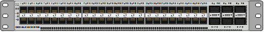
The 1RU Cisco Nexus 93180YC-FX3 switch (figure 10) with latency of less than 1 microsecond supports 3.6 Tbps of bandwidth and 1.2 billion packets per second. The 48 downlink ports on the switch can support 1-, 10-, or 25-Gbps Ethernet or as 16-, 32-Gbps Fibre Channel ports, creating a point of convergence for primary storage, compute servers, and back-end storage resources at the top of rack.
The configuration of the six 10-/25-/40-/50-/100-GE uplink ports offer flexible migration options.
Cisco MDS 9100 Series SAN Switches
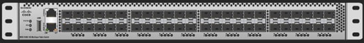
The Cisco MDS 9148T 32-Gbps 48-Port Fibre Channel switch is the next generation of the highly reliable, flexible, and low-cost Cisco MDS 9100 Series switches (Figure 11). It offers high-speed Fibre Channel connectivity for All-Flash arrays and state-of-the-art SAN analytics and telemetry capabilities built into its next-generation Application-Specific Integrated Circuit (ASIC) platform. The switch empowers small, midsize, and large enterprises that are rapidly deploying cloud-scale applications using extremely dense virtualized servers, providing the benefits of greater bandwidth, scale, and consolidation. Some of the main benefits for a small-scale Storage Area Network (SAN) are automatic zoning, nonblocking forwarding, and smaller port groups of 16 ports. Benefits for a mid- to large-size SAN include higher scale for Fibre Channel control-plane functions, virtual SANs, fabric login (FLOGI), device alias and name server scale, 48 ports of 32-Gbps non-oversubscribed line-rate ports, bidirectional airflow, and a fixed-form FC-NVMe-ready SAN switch with enhanced Buffer-to-Buffer (B2B) credits connecting both storage and host ports and Fibre Channel link encryption.
The Cisco MDS 9148T delivers advanced storage networking features and functions with ease of management and compatibility with the entire Cisco MDS 9000 Family portfolio for reliable end-to-end connectivity. The telemetry data extracted from the inspection of the frame headers are calculated on board (within the switch) and, using an industry-leading open format, can be streamed to any analytics-visualization platform. This switch also includes a dedicated 10/100/1000BASE-T telemetry port to maximize data delivery to any telemetry receiver, including Cisco Data Center Network Manager.
Cisco Nexus Dashboard Fabric Controller
The Cisco Nexus Dashboard Fabric Controller (NDFC), which is the evolution of Data Center Network Manager (DCNM), makes fabric management simple and reliable. It is the comprehensive management solution for all Cisco NX-OS network deployments spanning SAN fabrics, LAN fabrics, and IP fabric for media (IPFM) networking in the data center. Cisco NDFC provides management, control, automation, monitoring, visualization, and troubleshooting across Cisco Multilayer Switching (MDS) and Cisco Nexus solutions, reducing the complexities and costs of operating Cisco Nexus and storage network deployments while connecting and managing your cloud environments. Cisco NDFC is available through Cisco Data Center Networking (DCN) or NX-OS Essentials, Advantage, or Premier license and runs exclusively as a service on Cisco Nexus Dashboard.
Cisco Nexus Dashboard is managed through a web browser with various deployment options either as physical appliance or as virtual appliance like with VMware in a cluster setup with three VMware ESX virtual machines.
With the additional capability to discover and report about disk arrays in the fabric and the use of virtual machine managers, Cisco NDFC can effectively provide an end-to-end view of all communication within the data center. For customers adopting a combination of bare-metal and virtualized servers, the capability of Cisco NDFC to provide visibility into the network, servers, and storage resources makes this tool in high demand, helping provide full control of application Service-Level Agreements (SLAs) and metrics beyond simple host and virtual machine monitoring.
Cisco Intersight Nexus Dashboard Base
The Cisco Nexus Dashboard (ND) Base provides Cisco Technical Assistance Center (TAC) Assist functions that are useful when working with the dashboard. It provides a way for Cisco customers to collect technical support information across multiple devices and upload those tech supports to Cisco Cloud. The Cisco ND Base offers basic data center network assets, inventory, and status information in Cisco Intersight.
The Cisco ND Base application is connected to Cisco Intersight through a device connector that is embedded in the management controller of the Cisco NDFC platform. The device connector provides a secure way for connected Cisco NDFC to send and receive information from Cisco Intersight by using a secure Internet connection.
The Pure Storage FlashArray Family delivers software-defined all-flash power and reliability for businesses of every size. FlashArray is all-flash enterprise storage that is up to 10X faster, space and power efficient, reliable, and far simpler than other available solutions. At the top of the FlashArray line is FlashArray//X—the first mainstream, 100-percent NVMe, enterprise-class all-flash array. //X represents a higher performance tier for mission-critical databases, top-of-rack flash deployments, and tier 1 application consolidation. //X, at 1PB in 3RU, hundred-microsecond range latency, and GBs of bandwidth, delivers an unprecedented level of performance density. FlashArray//X is ideal for cost-effective consolidation of everything on flash, including accelerating a single database, scaling virtual desktop environments, or powering an all-flash cloud.
Purity for FlashArray (Purity//FA 6)
Every FlashArray is driven by Purity operating environment software. Purity//FA6 implements advanced data reduction, storage management, and flash management features, enabling customers to enjoy tier 1 data services for all workloads. Purity software provides proven 99.9999-percent availability over 2 years, completely nondisruptive operations, 2x better data reduction, and the power and efficiency of DirectFlash. Purity also includes enterprise-grade data security, comprehensive data-protection options, and complete business continuity with an ActiveCluster multi-site stretch cluster. All these features are included with every Pure Storage array.
Pure Storage FlashArray//X R3 Specification
Table 1 lists both capacity and physical aspects of various FlashArray systems. The Pure Storage FlashArray//X and //XL Series are certified for SAP HANA and do scale from 14 dedicated SAP HANA compute nodes per Pure Storage FlashArray//X10 to 55 dedicated SAP HANA compute nodes per Pure Storage FlashArray//XL170.
Table 1. Pure Storage FlashArray//X R3 and //XL specifications
|
|
Capacity |
Physical |
| //X10 |
Up to 73 TB/66.2 TiB (tebibyte) effective capacity** Up to 22 TB/19.2 TiB raw capacity |
3RU; 640-845 watts (nominal – peak) 95 lb. (43.1 kg) fully loaded; 5.12 x 18.94 x 29.72 in |
| //X20 |
Up to 314 TB/285.4 TiB effective capacity** Up to 94 TB/88 TiB raw capacity |
3RU; 741-973 watts (nominal – peak) 95 lb. (43.1 kg) fully loaded; 5.12 x 18.94 x 29.72 in |
| //X50 |
Up to 663 TB/602.9 TiB effective capacity** Up to 185 TB/171 TiB raw capacity |
3RU; 868-1114 watts (nominal – peak) 95 lb. (43.1 kg) fully loaded; 5.12 x 18.94 x 29.72 in |
| //X70 |
Up to 2286 TB/2078.9 TiB effective capacity** Up to 662 TB/544.2 TiB raw capacity |
3RU; 1084-1344 watts (nominal – peak) 97 lb. (44 kg) fully loaded; 5.12 x 18.94 x 29.72 in |
| //X90 |
Up to 3.3 PB/3003.1 TiB effective capacity** Up to 878 TB/768.3 TiB raw capacity |
3-6RU; 1160-1446 watts (nominal – peak) 97 lb. (44 kg) fully loaded; 5.12 x 18.94 x 29.72 in |
| //XL130 |
Up to 3.53 PB/3.3 PiB effective capacity** Up to 968 TB/880 TiB raw capacity |
5RU; 1550-2000 watts (nominal – peak) 167 lb. (75.7 kg) fully loaded; 8.72 x 18.94 x 29.72 in |
| //XL170 |
Up to 5.5 PB/5.13 TiB effective capacity** Up to 1.4 PB/1.31 PiB raw capacity |
5RU; 1550-2000 watts (nominal – peak) 167 lb. (75.7 kg) fully loaded; 8.72 x 18.94 x 29.72 in |
** Effective capacity assumes high availability, RAID, and metadata overhead, GB-to-GiB conversion, and includes the benefit of data reduction with always-on inline deduplication, compression, and pattern removal. Average data reduction is calculated at 5-to-1 and does not include thin provisioning.
Various connectivity options using both onboard and host I/O cards are available (Table 2).
Table 2. FlashArray//X network and Fibre Channel connectivity
| Chassis |
Onboard ports (per controller) |
Host I/O cards (3 slots/controller) |
|
| //X |
Two 1-/10-/25-GE |
2-port 10GBASE-T Ethernet |
2-port 25-/50 or 100-Gb NVMe/RoCE |
| //X |
Two 1-/10-/25-GE replication |
2-port 1-/10-/25-GE |
2-port 16-/32-Gb Fibre Channel (NVMe-oF Ready) |
| //X |
Two 1-Gb management ports |
2-port 40-GE |
4-port 16-/32-Gb Fibre Channel (NVMe-oF Ready) |
| //XL |
Two 1-/10-/25-GE |
2-port 1-/10-/25-GE |
2-port 25-/50 or 100-Gb NVMe/RoCE |
| //XL |
Four 10-/25-GE replication |
2-port 1-/10-/25-GE |
2-port 32-/64-Gb Fibre Channel (NVMe-oF Ready) |
| //XL |
Two 1-Gb management ports |
2-port 40-GE |
4-port 32-/64-Gb Fibre Channel (NVMe-oF Ready) |
Pure1
Pure1, a cloud-based management, analytics, and support platform, expands the self-managing, plug-n-play design of Pure all-flash arrays with the machine learning predictive analytics and continuous scanning of Pure1 Meta to enable an effortless, worry-free data platform.
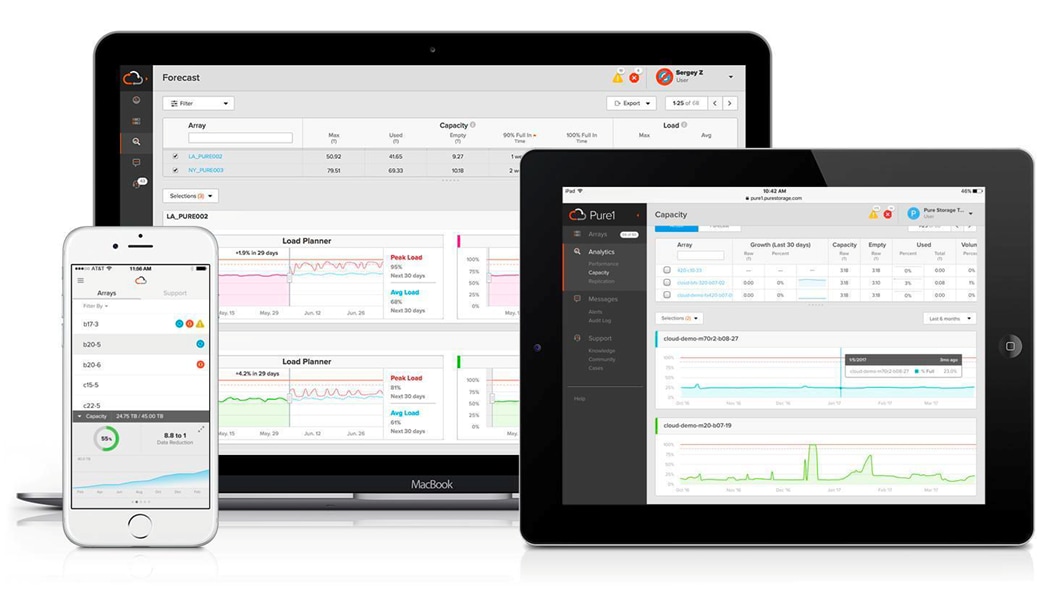
Pure1 Manage
Pure1 Manage is a SaaS-based offering that allows customers to manage their array from any browser or from the Pure1 Mobile App with nothing extra to purchase, deploy, or maintain. From a single dashboard, customers can manage all their arrays and have full storage health and performance visibility.
Pure1 Analyze
Pure1 Analyze delivers true performance forecasting, giving customers complete visibility into the performance and capacity needs of their arrays, now and in the future. Performance forecasting enables intelligent consolidation and workload optimization.
Pure1 Support
Pure Storage support team with the predictive intelligence of Pure1 Meta delivers unrivaled support that’s a key component in FlashArray 99.9999% availability. Some of the customer issues are identified and fixed without any customer intervention.
Pure1 META
The foundation of Pure1 services, Pure1 Meta is global intelligence built from a massive collection of storage array health and performance data. By continuously scanning call-home telemetry from Pure’s installed base, Pure1 Meta uses machine learning predictive analytics to help resolve potential issues, optimize workloads, and provide accurate forecasting. Meta is always expanding and refining what it knows about array performance and health.
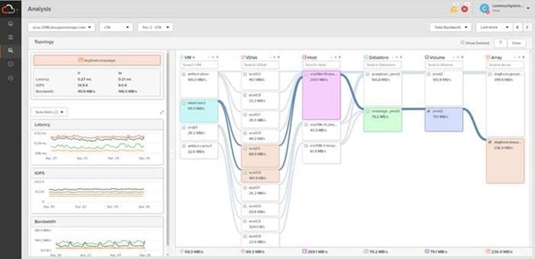
Pure1 VM Analytics
Pure1 helps you narrow down the troubleshooting steps in your virtualized environment. VM Analytics provides you with a visual representation of the IO path from the VM all the way through to the FlashArray. Other tools and features guide you through identifying where an issue might be occurring to help eliminate potential candidates for a problem.
VM Analytics doesn’t only help when there’s a problem. The visualization allows you to identify which volumes and arrays particular applications are running on. This brings the whole environment into a more manageable domain.
SAP HANA is a multi-model database that stores data in-memory instead of keeping it on disks. The column oriented in-memory database design allows you to run advanced analytics alongside high-speed transactions in a single system. Even though SAP HANA is an in-memory data platform, it requires a high performing persistence layer which can be based on a storage area network (SAN) like with FlashStack.
The SAP HANA Tailored Datacenter Integration (TDI) provides the flexibility to build infrastructure solutions including many kinds of virtualization, network, and storage technology options. While it crucial to understand the limits and requirements of an SAP HANA TDI environment, the FlashStack for SAP HANA TDI solution helps to consolidate the whole SAP landscape whether virtualized or bare metal to a single, central, and performant FlashArray//X.
FlashStack offer SAP HANA TDI deployments a distinct advantage due to the following reasons:
● The Pure Storage FlashArray//X product line is a 100% NVMe storage solution providing low latency for both the log and data areas in any SAP HANA TDI deployment.
● The FlashStack SAP alliance is SAP TDI certified to provide organizations with the flexibility to choose the best, cost-effective, and appropriate solution that meets their needs. Deployment option scales from on-prem into the cloud.
● The Evergreen product model allows organizations to increase performance, scalability, and capacity over time without the need to purchase an entirely new storage.
● Pure Storage FlashArray includes a range of data services aimed at enabling customers to realize the full potential of their SAP HANA deployment, namely ActiveCluster and Multi-Site replication.
SAP HANA offers its own internal business continuity approach for data protection and replication solutions each of which is integrated into the core product. Business continuity can be achieved by utilizing a scale up or scale out instance with one or more failover nodes, backups to NFS or an SAP Backint certified storage target, storage replication and system replication.
For more information about the FlashArray Protection for SAP HANA, see: https://support.purestorage.com/Solutions/SAP/SAP_HANA_on_FlashArray.
SAP Application Monitoring with AppDynamics
AppDynamics is an Application Performance Monitoring (APM) Platform that helps you to understand and optimize the performance of your business, from its software to infrastructure to business journeys.
The AppDynamics APM Platform enables you to monitor and manage your entire application-delivery ecosystem, from the mobile app or browser client request through your network, backend databases and application servers and more. AppDynamics APM gives you a single view across your application landscape, letting you quickly navigate from the global perspective of your distributed application right down to the call graphs or exception reports generated on individual hosts.
AppDynamics has an agent-based architecture. Once the agents are installed you receive a dynamic flow map or topography of your application. It uses the concept of traffic lights to indicate the health of your application (green is good, yellow is slow, and red indicates potential issues) with dynamics baselining. AppDynamics measures application performance based on business transactions which essentially are the key functionality of the application. When the application deviates from the baseline AppDynamics captures and provides deeper diagnostic information to help be more proactive in troubleshooting and reduce the MTTR (Mean Time To Repair).
For more information about SAP monitoring using AppDynamics, see: https://docs.appdynamics.com/display/SAP/SAP+Monitoring+Using+AppDynamics.
VMware vSphere is a virtualization platform for holistically managing large collections of infrastructures (re-sources including CPUs, storage, and networking) as a seamless, versatile, and dynamic operating environment. Unlike traditional operating systems that manage an individual machine, VMware vSphere aggregates the infra-structure of an entire data center to create a single powerhouse with resources that can be allocated quickly and dynamically to any application in need.
Running SAP HANA TDI virtualized on vSphere delivers a software-defined deployment architecture to SAP HANA customers, which will allow easy transition between private, hybrid or public cloud environments.
Using the SAP HANA platform with VMware vSphere virtualization infrastructure provides an optimal environment for achieving a unique, secure, and cost-effective solution and provides benefits physical deployments of SAP HANA cannot provide, such as:
● Higher service-level agreements (SLAs) by leveraging vSphere vMotion® to live migrate running SAP HANA instances to other vSphere host systems before hardware maintenance or host resource constraints.
● Standardized high availability solution based on vSphere High Availability.
● Built-in multitenancy support via SAP HANA system encapsulation in a virtual machine (VM).
● Easier hardware upgrades or migrations due to abstraction of the hardware layer.
● Higher hardware utilization rates.
● Automation, standardization and streamlining of IT operation, processes, and tasks.
● Cloud readiness due to software-defined data center (SDDC) SAP HANA deployments.
These and other advanced features found almost exclusively in virtualization lower the total cost of ownership and ensure the best operational performance and availability. FlashStack for SAP HANA TDI fully supports SAP HANA and related software in production environments, as well as SAP HANA features such as SAP HANA multitenant database containers (MDC) or SAP HANA system replication (HSR).
For more information about VMware vSphere and its components, see: https://www.vmware.com/products/vsphere.html.
VMware vSphere vCenter
VMware vCenter Server provides unified management of all hosts and VMs from a single console and aggregates performance monitoring of clusters, hosts, and VMs. VMware vCenter Server gives administrators a deep insight into the status and configuration of compute clusters, hosts, VMs, storage, the guest OS, and other critical components of a virtual infrastructure. VMware vCenter manages the rich set of features available in a VMware vSphere environment.
Cisco Intersight Assist Device Connector for VMware vCenter and Pure Storage FlashArray//X
Cisco Intersight integrates with VMware vCenter, and Pure Storage FlashArray//X as follows:
● Cisco Intersight uses the device connector running within Cisco Intersight Assist virtual appliance to communicate with the VMware vCenter.
● Cisco Intersight uses the device connector running within a Cisco Intersight Assist virtual appliance to integrate with Pure Storage FlashArray//X.
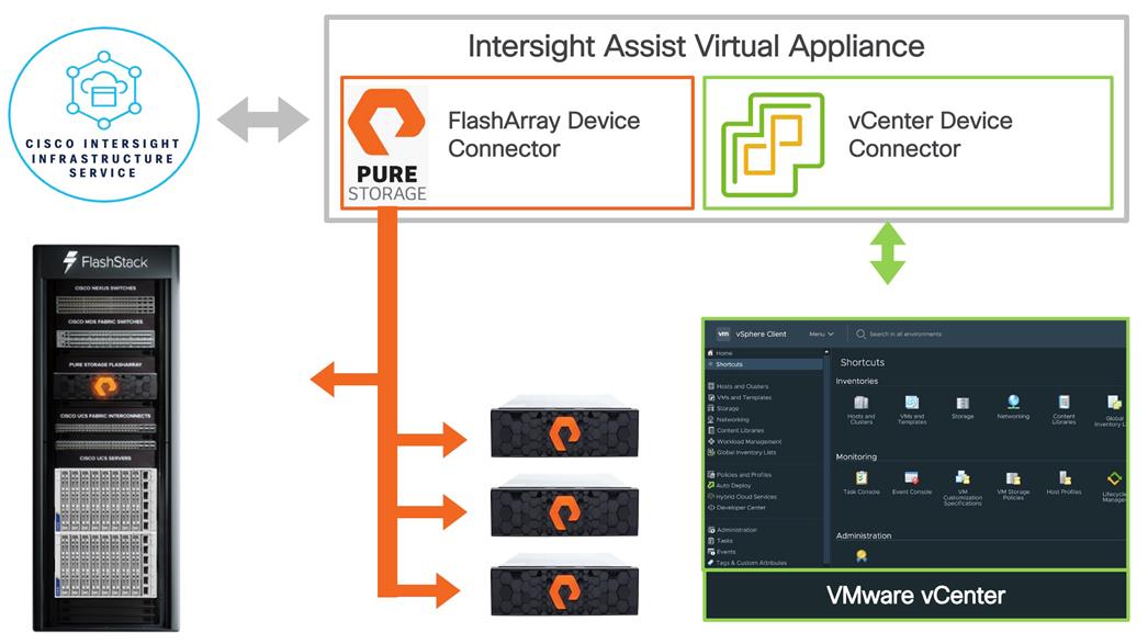
The device connector provides a safe way for connected targets to send information and receive control instructions from Cisco Intersight using a secure Internet connection. The integration brings the full value and simplicity of Cisco Intersight infrastructure management service to VMware hypervisor and FlashArray storage environments. The integration architecture enables FlashStack customers to use new management capabilities with no compromise in their existing VMware or FlashArray operations. IT users will be able to manage heterogeneous infrastructure from a centralized Cisco Intersight portal. At the same time, the IT staff can continue to use VMware vCenter and the Pure Storage dashboard for comprehensive analysis, diagnostics, and reporting of virtual and storage environments.
Red Hat Ansible Automation Platform
Red Hat Ansible Automation Platform provides an enterprise framework for building and operating IT automation across an organization. It is simple and powerful, allowing users to easily manage various physical devices within FlashStack including the provisioning of Cisco UCS bare metal servers, Cisco Nexus and MDS switches, Pure Storage FlashArray//X and VMware vSphere. Using Ansible’s Playbook-based automation provides a more secure and stable foundation for deploying end-to-end infrastructure automation.
This solution offers Ansible Playbooks that are made available from a GitHub repository that customers can access to automate the FlashStack deployment.
Red Hat Enterprise Linux for SAP Solutions
Red Hat Enterprise Linux for SAP Solutions is an SAP specific offering, tailored to the needs of SAP workloads such as S/4HANA and SAP HANA platform. Furthermore, standardizing your SAP environment on Red Hat Enterprise Linux for SAP Solutions helps streamline operations and reduce costs by providing integrated smart management and high availability solutions as part of the offering.
Built on Red Hat Enterprise Linux (RHEL), the RHEL for SAP Solutions subscription offers the following additional components:
● SAP-specific technical components to support SAP S/4HANA, SAP HANA, and SAP Business Applications.
● High Availability solutions for SAP S/4HANA, SAP HANA, and SAP Business Applications.
● RHEL System Roles for SAP, which can be used to automate the configuration of a RHEL system to run SAP workloads.
● Smart Management and Red Hat Insights for lifecycle management and proactive optimization.
● Update Services and Extended Update Support
SUSE Linux Enterprise Server for SAP Applications
SUSE Linux Enterprise Server (SLES) for SAP Applications is the leading Linux platform for SAP HANA, SAP NetWeaver, and SAP S/4HANA solutions providing optimized performance and reduced downtime as well as faster SAP landscape deployments.
The key features of SLES for SAP Applications are:
● Deploy SAP services faster with automation. Automate installation of the complete SAP stack including the operating system (OS), SAP workloads, high availability (HA), and monitoring. Avoid delays with saptune configuration of the OS and HA configuration, optimized for specific SAP applications.
● Reduce downtime and increase security. Reduce outages with HA configurations designed for SAP HANA, and SAP applications. Eliminate downtime for Linux security updates with live kernel patching.
● Avoid errors with advanced monitoring. Monitor key metrics with Prometheus exporters for server and cloud instances, SAP HANA, SAP applications, and high availability cluster operations for visualization with SUSE Manager or other graphical display tools.
● Safeguard SAP Systems to prevent errors. Automatically discover and enable full observability of servers, SAP HANA databases, SAP S/4HANA and NetWeaver applications, and clusters with Trento in SAP domain language. Continuously check HA configurations, visualize potential problems, and apply recommended fixes.
This chapter is organized as follows:
The FlashStack for SAP HANA TDI powered by Cisco UCS X-Series and Cisco UCS B-Series delivers a cloud-managed infrastructure solution on the latest Cisco UCS hardware. VMware vSphere 7.0 U3c hypervisor is installed on the Cisco UCS X210c M6 compute nodes and Cisco UCS B480 M5 blade servers in a stateless compute design using boot from SAN. Pure Storage FlashArray//X50 R3 provides the storage infrastructure to setup up the VMware environment. Configure and manage the infrastructure using the Cisco Intersight cloud-management platform. The solution requirements and design details are explained in this chapter.
The FlashStack for SAP HANA TDI with Cisco UCS X-Series solution design meets the following general design requirements:
● Resilient design across all layers of the infrastructure with no single point of failure.
● Scalable design with flexibility to add compute capacity, storage, or network bandwidth as needed.
● Modular design that you can replicate to expand and grow as the needs of your business grow.
● Flexible design that can easily support different models of various components.
● Simplified design with ability to automate and integrate with external automation tools.
● Cloud-enabled design that you can configure, manage, and orchestrate from the cloud using a graphical user interface (GUI) or APIs.
Table 3 and Table 4 list the required physical components as well as the hardware and software releases used during solution validation. It is important to note that this validated FlashStack solution adheres to Cisco, Pure Storage, VMware and SAP interoperability matrix and SAP notes to determine a supported configuration for this design guide.
Table 3. FlashStack for SAP HANA TDI system components
| Component |
Hardware |
| Fabric Interconnects |
Two (2) Cisco UCS 6454 Fabric Interconnects |
| Servers |
Minimum of (3) three Cisco UCS X210c M6 compute nodes including (1) one Cisco UCS X9508 chassis |
| Storage |
Minimum of (1) one Pure Storage FlashArray//X R3 |
| Storage networking |
Minimum of (2) Cisco MDS 9100 Series Multilayer Fabric Switches |
| Networking |
Minimum of (2) Cisco Nexus 9300 Series switches |
| Management Server |
Minimum of (1) Cisco UCS C220 M6 rack server |
Table 4 lists the minimum software release requirements for the FlashStack for SAP HANA TDI solution, as tested, and validated in this document.
Table 4. Software Components and Revision
| Component |
Software Revision |
| Fabric Interconnects |
Cisco Intersight Infrastructure Bundle 4.2(2c) or later |
| Cisco UCS X-Series Server |
Cisco UCS X-Series Server Firmware, revision 5.0(2d) or later |
| Cisco UCS B-Series M5 Server |
Cisco Intersight Server Bundle, revision 4.2(2d) or later |
| Cisco VIC enic driver for ESXi |
1.0.42.0 |
| Cisco VIC fnic driver for ESXi |
5.0.0.37 |
| Pure Storage FlashArray//X 50 R3 |
Purity//FA 6.3.7 |
| Pure Storage VASA provider |
3.5 |
| Pure Storage Plugin |
5.0.0 |
| Cisco Nexus 93180YC-FX3 |
Cisco Nexus 9000 Series NX-OS Release 9.3(10) or later |
| Cisco MDS 9148T |
MDS NX-OS Release 8.4(2c) or 9.3(2) and later |
| Cisco Intersight Assist |
Cisco Intersight Virtual Appliance and Assist for vSphere 1.0.9-499 |
| VMware vSphere 7 |
VMware ESXi 7.0 Update 3c or later |
| Red Hat |
Red Hat Enterprise Linux 8.6 for SAP Solutions |
| SUSE |
SUSE Linux Enterprise for SAP Applications 15 SP4 |
Cisco Unified Computing System is composed of a pair of Cisco UCS Fabric Interconnects along with up to 160 Cisco UCS X-Series, Cisco UCS B-Series blade servers, or Cisco UCS C-Series rack-mount servers per UCS domain. Inside of a Cisco UCS domain, multiple environments can be deployed for differing workloads. The FlashStack solution in general supports both IP- and FC-based storage access designs; nevertheless, to be fully supported SAP HANA workload demands a FC-based storage access design. In the FC-based storage design the Fabric Interconnect uplink ports connect to the Pure Storage FlashArray//X using Cisco MDS 9148T switches for storage access, including boot from SAN.
The same principles apply to Cisco UCS B- and C-Series (when connected to fabric interconnects), and Cisco UCS X-Series. The two Fabric Interconnects both connect to Cisco UCS C-Series, Cisco UCS 5108 blade chassis, and every Cisco UCS X9508 chassis. Upstream network connections, also referred to as “northbound” network connections are made from the Fabric Interconnects to the customer datacenter network at the time of installation.
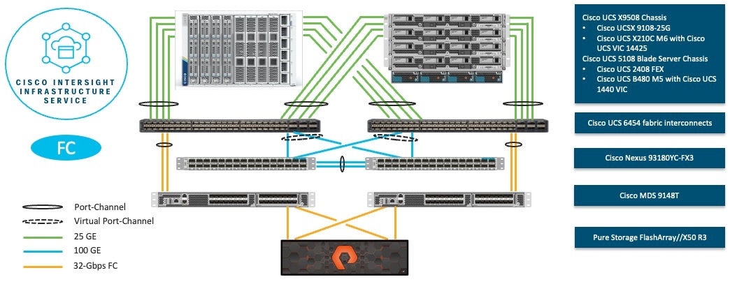
To validate the FC-based storage access in a FlashStack configuration, the components are set up as follows:
● Cisco UCS 6454 Fabric Interconnects provide chassis and network connectivity.
● The Cisco UCS X9508 chassis connects to fabric interconnects using Cisco UCSX 9108-25G Intelligent Fabric Modules (IFMs), where four 25 Gigabit Ethernet ports are used on each IFM to connect to the appropriate FI.
● Cisco UCS X210c M6 compute nodes contain fourth-generation Cisco 14425 virtual interface cards.
● The Cisco UCS 5108 Blade server chassis connects to fabric interconnects using Cisco UCS 2408 IOM modules, where four 25 Gigabit Ethernet ports are used on each IOM to connect to the appropriate FI.
● Cisco UCS B480 M5 blade servers contain fourth-generation Cisco 1440 virtual interface cards.
● Cisco Nexus 93180YC-FX3 Switches in Cisco NX-OS mode provide the switching fabric.
● Cisco UCS 6454 Fabric Interconnect 100 Gigabit Ethernet uplink ports connect to Cisco Nexus 93180YC-FX3 Switches in a virtual port-channel (vPC) configuration.
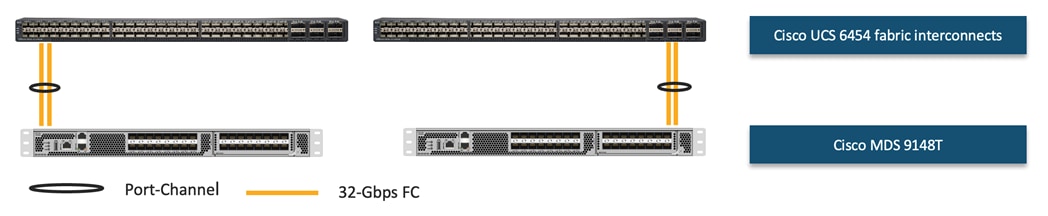
● Cisco UCS 6454 Fabric Interconnects are connected to the Cisco MDS 9148T switches using 32-Gbps Fibre Channel connections configured as a single port-channel (pc) for SAN connectivity.
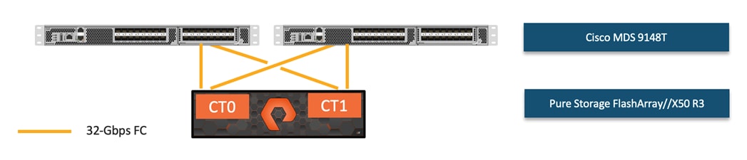
● The Pure Storage FlashArray//X50 R3 connects to the Cisco MDS 9148T switches using 32-Gbps Fibre Channel connections for SAN connectivity.
● VMware 7.0 U3c ESXi software is installed on Cisco UCS X210c M6 compute nodes and Cisco UCS B480 M5 blade servers to validate the infrastructure.
● Red Hat Enterprise Linux 8.6 for SAP Solutions and SUSE Linux Enterprise 15 SP4 for SAP Applications is installed on Cisco UCS X210c M6 servers and Cisco UCS B480 M5 servers to validate the infrastructure.
● SAP HANA platform edition 2.0 SPS06 is installed as virtual instance or bare metal to validate the infrastructure.
To install the FlashStack environment, the following VLANs are recommended:
| VLAN ID |
Name |
Usage |
| 2 |
Native-VLAN |
Use VLAN 2 as native VLAN instead of the default VLAN 1. |
| 3072 |
OOB-MGMT-VLAN |
Out-of-band management VLAN to connect management ports for various devices |
| 76 |
IB-MGMT-VLAN |
In-band management VLAN utilized for all in-band management connectivity – for example, ESXi hosts, VM management, and other infrastructure services. |
| 172 |
VM-Traffic |
VMware virtual machine data traffic; use multiple VLANs depending on the SAP HANA requirements. |
| 10 |
fcoe_vlan_id_on_fi_a |
FCoE VLAN ID for Fabric Interconnect A |
| 20 |
fcoe_vlan_id_on_fi_b |
FCoE VLAN ID for Fabric Interconnect B |
| 3319 |
vMotion |
VMware vMotion traffic |
Out-of-band configuration for the components configured as in-band can be enabled, however this requires additional uplink ports on the 6454 Fabric Interconnects if the out-of-band management is kept on a separate out-of-band switch. A disjoint layer-2 configuration allows a complete separation of the management and data plane networks. This setup requires additional vNICs on each server, which are then associated with the management uplink ports.
Table 6 lists the VSANs configured for setting up the FlashStack environment along with their usage.
| VSAN ID |
Name |
Usage |
| 101 |
fcoe_vlan_id_on_fi_a |
VSAN ID of MDS-A switch for boot-from-SAN and SAP HANA storage access |
| 102 |
fcoe_vlan_id_on_fi_b |
VSAN ID of MDS-B switch for boot-from-SAN and SAP HANA storage access |
A pair of VSAN IDs (101 and 102) are configured to provide block storage access for the ESXi or Linux hosts and the SAP HANA data, log, and shared volumes.
In FlashStack deployments, each Cisco UCS server equipped with a Cisco Virtual Interface Card (VIC) is configured for multiple virtual Network Interfaces (vNICs), which appear as standard-compliant PCIe endpoints to the OS. The end-to-end logical connectivity including VLAN/VSAN usage between the server profile for an ESXi host and the storage configuration on Pure Storage FlashArray is captured in the following subsections.
Logical topology for FC-based storage access
FlashStack for SAP HANA TDI running on Cisco UCS has communication pathways that fall into two defined zones:
● Management Zone: This zone comprises the connections needed to manage the physical hardware, and the configuration of the Cisco UCS domain. These interfaces and IP addresses need to be available to all staff who will administer the Cisco UCS system, throughout the LAN/WAN. All IP addresses in this zone must be allocated from the same layer 2 (L2) subnet. This zone must provide access to Domain Name System (DNS), Network Time Protocol (NTP) services, and allow communication through HTTP/S and Secure Shell (SSH). In this zone are multiple physical and virtual components:
◦ Fabric Interconnect management ports.
◦ Cisco Intelligent Management Controller (CIMC) management interfaces used by each the rack-mount servers, blades, and compute nodes, which answer through the FI management ports.
◦ IPMI access over LAN, allowing Cohesity Operation System to obtain information about system hardware health to proactively raise alerts and warnings.
◦ Cisco Nexus and MDS switch management ports.
◦ Pure Storage FlashArray//X management port.
● Application Zone: This zone comprises the connections used by VMware vSphere and the underlying operating system on the nodes. These interfaces and IP addresses need to be able to always communicate with each other for proper operation, and they must be allocated from the same L2 subnet. The VLAN used for VMware traffic must be accessible to/from all environments utilizing VMware vSphere Services, such as the FlashArray//X or external backup software. This zone must provide access to Domain Name System (DNS), Network Time Protocol (NTP) services, and allow communication through HTTP/S and Secure Shell (SSH). Finally, the VLAN must be able to traverse the network uplinks from the Cisco UCS domain, reaching FI A from FI B directly through the northbound switches, and vice-versa. In this zone are multiple components:
● A static IP address configured for the underlying Linux operating system of each VMware machine (VM). Four Cisco UCS vNICs are configured per node, equally distributed on the A and B side fabric. Two interfaces (vSwitch0-A and vSwitch0-B) carry the management traffic, the other two interfaces for the vSphere Distributed switches (VDS-A and VDS-B) carry the VMware vMotion traffic.
● For SAP HANA bare-metal installations a static IP address configured for the underlying Linux operating system. Two Cisco UCS vNICs are configured per node, one on the A side fabric and the other on the B side fabric. With the switch configured for IEEE 802.3ad Dynamic link aggregation, the two interfaces are configured in LACP teaming mode within the Linux operating system.
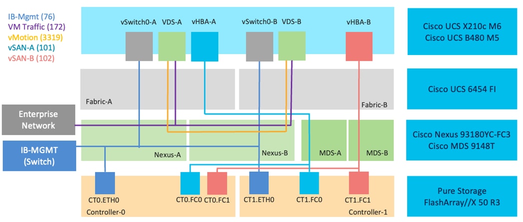
Each Intersight server profile for ESXi nodes supports:
● Managing the ESXi hosts using a common management segment
● Diskless SAN boot with persistent operating system installation for true stateless computing
● Four vNICs where:
Two redundant vNICs (vSwitch0-A and vSwitch0-B) carry management traffic. The MTU value for these vNICs is set as a Jumbo MTU (9000).
The vSphere Distributed switch uses two redundant vNICs (VDS-A and VDS-B) to carry VMware vMotion traffic and customer application data traffic. The MTU for the vNICs is set to Jumbo MTU (9000).
● Two vHBAs with one vHBA defined for Fabric-A and Fabric-B each to provide access to the SAN paths.
● Each ESXi host (compute node) accesses datastores from the Pure Storage FlashArray//X to deploy virtual machines.
Note: In a mixed environment with bare-metal SAP HANA hosts create, apart from in-band management, individual vNICs corresponding to the SAP HANA network requirements.
Cisco UCS compute system connectivity
The Cisco UCS X9508 chassis is equipped with Cisco UCS 9108-25G IFMs to provide network and storage connectivity. In the validated design with four Cisco UCS X210c M6 each IFM connects with four 25GE ports to the pair of Cisco UCS 6454 Fabric Interconnects. For more bandwidth when using up to eight compute nodes, connect all eight ports of the IFMs to the Fabric Interconnects.
The Cisco UCS 5108 chassis is equipped with Cisco UCS VIC 1440 is a single-port 40-Gbps or four-port 10-Gbps Ethernet/FCoE capable modular LAN on Motherboard (mLOM). When used in combination with an optional port expander, the Cisco VIC 1440 capabilities are enabled for two ports of 40-Gbps Ethernet per Fabric Interconnect.
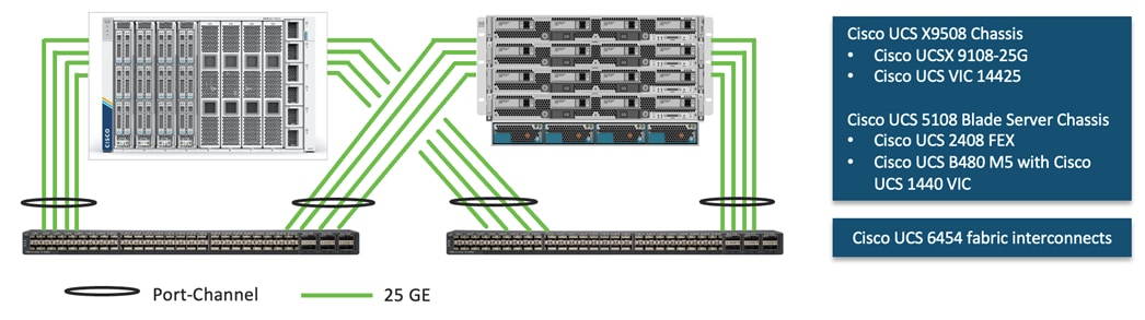
Cisco UCS 6454 Fabric Interconnect Ethernet connectivity
The pair of Cisco UCS 6454 Fabric Interconnects (FIs) are connected to Cisco Nexus 93180YC-FX3 switches using 100GE connections configured as virtual port channels. Each FI is connected to both Cisco Nexus switches using a 100G connection; additional links can easily be added to the port channel to increase the bandwidth as needed.
Cisco Nexus Ethernet connectivity
The Cisco Nexus 93180YC-FX3 device configuration covers the core networking requirements for Layer 2 and Layer 3 communication. Some of the key NX-OS features implemented within the design are:
● Feature interface-vlan – Allows for VLAN IP interfaces to be configured within the switch as gateways.
● Feature HSRP – Allows for Hot Standby Routing Protocol configuration for high availability.
● Feature LACP – Allows for the utilization of Link Aggregation Control Protocol (802.3ad) by the port channels configured on the switch.
● Feature vPC – Virtual Port-Channel (vPC) presents the two Nexus switches as a single “logical” port channel to the connecting upstream or downstream device.
● Feature LLDP - Link Layer Discovery Protocol (LLDP), a vendor-neutral device discovery protocol, allows the discovery of both Cisco devices and devices from other sources.
● Feature NX-API – NX-API improves the accessibility of CLI by making it available outside of the switch by using HTTP/HTTPS. This feature helps with configuring the Cisco Nexus switch remotely using the automation framework.
● Feature UDLD – Enables unidirectional link detection for various interfaces.
Pure Storage FlashArray//X50 R3 Ethernet connectivity
Each Pure Storage FlashArray//X50 controller connects to the Cisco Nexus 93180YC-FX3 switch pair with two 25GE ports. The NFS shared storage connectivity is required for SAP HANA TDI scale-out environments running on the Cisco UCS B480 M5 Blade servers.
Cisco MDS SAN connectivity
In the FlashStack Fibre Channel (FC) storage design the Cisco MDS 9148T switch is the key design component. According to the size of their deployment and their disaster recovery needs, customers can select the appropriate model in the Cisco MDS 9000 Series, from the cost-effective Cisco MDS 9148T switch to the flexible Cisco MDS 9220i multiprotocol switch, or the largest director, such as the Cisco MDS 9718 Multilayer Director.
Connecting Cisco fabric interconnects in end-host mode to Cisco MDS 9000 Series switches requires the N-Port ID Virtualization (NPIV) feature to be enabled on the Cisco MDS 9000 Series switches. To reduce administrative burden, and for an optimized support of modern NVMe/FC disk arrays, the NPIV feature is enabled by default globally in recent NX-OS releases.
Advanced design options become possible with the combined solution, and this is one of the main benefits. End-to-end VSANs, VSAN trunking, and Inter-VSAN Routing (IVR) are additional benefits for those seeking multitenancy in the data center. Increased high availability and uniform uplink utilization are achieved with the help of the exclusive Fabric-port (F-port) Port Channel technology, avoiding host re-login in the event of a link failure. Provision for NVMe/FC is present within Cisco UCS and Cisco MDS 9000 Series, leading to better performance for application workloads.
Easier management is another major outcome. Common Cisco NX-OS Software operating system and management tools, such as Cisco Nexus Dashboard Fabric Controller (NDFC) and Cisco Intersight, create a uniform and homogeneous solution. IT administrators can use the same skills across computing, SAN, and LAN environments. Cisco Smart Zoning reduces administration overhead without sacrificing end-node control. Automated and multitenant hybrid clouds can be created from those building blocks.
Cisco UCS Fabric Interconnect SAN connectivity
Each Cisco UCS 6454 Fabric Interconnect connects to a Cisco MDS 9132T SAN switch using a redundant 32G Fibre Channel port-channel connection.
Pure Storage FlashArray//X50 R3 SAN connectivity
For redundancy, each individual Pure FlashArray controller connects with dual port 32G Fibre Channel connections to both of Cisco MDS 9132T SAN switches. To support Fibre Channel multipathing, the compute hosts have two HBAs available supplementing the SAN multipathing configuration. If performance or business rules require it is always possible to add additional dual port FC cards to extend the design to eight 32G Fibre Channel ports.
This chapter is organized as follows:
● Interoperability and Feature Compatibility
● Network and SAN Design Considerations
● Pure Storage FlashArray Considerations
● vCenter Deployment Consideration
Some of the key design considerations vital to the performance and reliability for FlashStack for SAP HANA TDI with Cisco UCS X-Series and VMware 7.0 U3c will be discussed in this chapter.
Interoperability and Feature Compatibility
Any time that devices are interconnected, interoperability needs to be verified. Verification is particularly important in the storage environment. Every vendor publishes its own interoperability matrices (also known as hardware and software compatibility lists). Cisco UCS is no different in this respect. Of course, full interoperability is much easier to achieve with products from the same vendor because they come from the same engineering organization and are readily available for internal testing.
The different hardware and software compatibility tools are available at the following links:
● Cisco UCS Hardware and Software Interoperability Matrix
● Cisco MDS and Nexus Interoperability Matrix
● Pure Storage Interoperability Matrix
● Pure Storage FlashStack Compatibility Matrix
In addition to the hardware components the software product features need to fully integrate with SAP solutions which is confirmed with SAP certifications and SAP notes accordingly:
● Certified and supported SAP HANA hardware
● SAP note 2235581 – SAP HANA: Supported Operating Systems
● SAP note 2937606 – SAP HANA on VMware vSphere 7.0 in production
To achieve the performance and reliability requirements for SAP HANA it is vital to select the correct components and configuration for the SAP landscape.
Bare-metal Installation
The existing core-to-memory ratios for SAP HANA bare-metal environments are dependent on the Intel CPU architecture and the type of SAP data processing: online analytical processing (OLAP), online transaction processing (OLTP), or a mixed data processing system like with SAP Suite on/for HANA (SoH/S4H).
With these dependencies the 2-socket, Intel Ice Lake CPU architecture-based Cisco UCS X210c compute node can scale up to 2 TB DDR main memory for SAP Business Warehouse (BW) systems or 4 TB DDR main memory for SAP Suite systems.
The 4-socket, Cascade Lake CPU architecture-based Cisco UCS B480 M5 Blade server can scale up to 3 TB for SAP BW systems or 6 TB for SAP Suite and they enable the option to build an SAP HANA scale-out environment with multiple 4-socket nodes: up to 16 nodes for SAP Business Warehouse environments and up to 4 nodes for SAP Suite environments.
With SAP expert sizing mixed memory configurations of DDR memory and Intel Persistent Memory (PMem) using the AppDirect mode of the Intel PMem modules can increase the amount of available memory for the SAP HANA in-memory database further.
Network requirements depend on the client and application, backup/storage connectivity, and optional system replication and cluster services access. At a minimum, the application server access network is required. For SAP HANA scale-out environments an additional node-to-node network with a recommended minimum of 10 Gigabit is required.
Virtualized Installation
Since SAP HANA TDI Phase 5, it is possible to perform a workload-based sizing (SAP note 2779240) which can deviate from the existing core-to-memory ratio if the following conditions are met:
● Certified SAP HANA hardware
● Validated hypervisor
● Deviations are within the upper and lower limits of the hypervisor
VMware vSphere and Intel Ice Lake CPUs are validated for SAP HANA starting with VMware vSphere 7.0 U3c which is the recommended release for the whole FlashStack configuration.
VMware virtual SAP HANA sizing gets performed just like physically deployed SAP HANA systems. The major difference is that an SAP HANA workload needs to fit into the compute and RAM maximums of a VM and that the costs of virtualization (RAM and CPU costs of the ESXi) need to get considered when planning an SAP HANA deployment.
The minimum host requirement is a 2-CPU socket node, and the minimum vHANA size is 0.5-CPU socket reserved with 8vCPUs based on 8 physical cores and 128 GB main memory. The upper limits dependent on the number of sockets, CPU models and cores, and vSphere versions:
● Cisco UCS M5 B-Series (Cascade Lake)
◦ Cisco UCS B200 M5: 112 vCPUs and 2-CPU socket wide VMs
◦ Cisco UCS B480 M5: 224 vCPUs and 4-CPU socket wide VMs
● Cisco UCS M6 X-Series (Ice Lake)
◦ Cisco UCS X210c M6: 160 vCPUs and 2-CPU socket wide VMs
The recommended approach to configure vHANA machines is to match the actual hardware configuration in regards of the number of cores per socket and available total amount of memory. For example, a 0.5-CPU socket configuration for the Intel Xeon Platinum 8380 processor with 40 cores per socket, configure 20 physical cores and ¼ of the available main memory. If SAP HANA requires more memory double the physical cores and memory. Odd VM configurations like 1.5 or 2.5-CPU sockets are not allowed. It is possible to run up to 4 individual vHANA production machines on a single Cisco UCS X210c M6 compute node.
Note: SAP HANA VMs can get co-deployed on a ESXi host server with SAP non-production HANA VMs or other workload VMs. SAP HANA production VMs must run on dedicated CPUs (NUMA nodes). Half-Socket SAP HANA VMs can share the CPU socket with other SAP HANA half-socket VMs but sharing the CPU socket with non-SAP HANA VMs is not supported for SAP HANA production VMs.
For each SAP HANA node in a virtual machine, a data volume; a log volume; and a volume for executable files, configurations, and application logs are configured. The persistence volumes for the SAP HANA system are carved out of the dedicated Virtual Machine File System (VMFS) datastore. The SAP HANA binary file system is mounted directly on the provisioned SAP HANA virtual machine using the dedicated FC connection to the storage.
The storage configuration and sizing for a virtualized SAP HANA system is identical to the one for bare-metal servers. The existing SAP HANA storage requirements for the partitioning, configuration, and sizing of data, log, and binary volumes remain valid for virtualization scenarios.
Network requirements depend on the client and application, backup/storage connectivity, and optional system replication and cluster services access. For a 2-socket host the recommended minimum network configuration is two times 10 GbE for vMotion/HA and two times 10 GbE for the application server access network. For a 4-socket host the recommended network bandwidth is 25 GbE.
Co-existing SAP HANA and SAP Application Workloads
With SAP HANA TDI it is possible to run SAP HANA on shared infrastructure that also hosts non-HANA workloads like standard SAP applications. Scenarios where SAP HANA database bare metal installation along with virtualized SAP application workloads are common in the datacenter. It is important to ensure appropriate storage IO and network bandwidth segregation so that HANA systems satisfy the storage and network KPIs for production support.
Network and SAN Design Considerations
Connectivity
For the Cisco UCSX-9508 chassis, a pair of Cisco UCS 9108-25G IFMs provide network connectivity with four 25 Gbps lanes per compute node in the chassis. The design of the Cisco UCSX-9508 enables easy upgrades from 25-Gb to 100-Gb uplink ports by replacing the IFMs with two Cisco UCS 9108 100G IFMs which can provide full 100 Gbps connectivity when using 100G transceiver modules.
Out-of-band Management Network
The management interface of every physical device in FlashStack is connected to a dedicated out-of-band management switch, which can be part of the existing management infrastructure in a customer’s environment. The out-of-band management network provides management access to all the devices in FlashStack for initial and on-going configuration changes. The routing and switching configuration for this network is independent of FlashStack deployment and therefore changes in FlashStack configurations do not impact management access to the devices.
In-band Management Network
The in-band management VLAN configuration is part of FlashStack design. The in-band VLAN is configured on Nexus switches and Cisco UCS within the FlashStack solution to provide management connectivity for vCenter, ESXi and other management components. The changes to FlashStack configuration can impact the in-band management network and misconfigurations can cause loss of access to the management components hosted on the FlashStack.
Cisco Nexus 9000 Series vPC Best Practices
The following Cisco Nexus 9000 vPC design best practices and recommendations were used in this design:
● vPC peer keepalive link should not be routed over a vPC peer-link.
● The out-of-band management network is used as the vPC peer keepalive link in this design.
● Only vPC VLANs are allowed on the vPC peer-links. For deployments that require non-vPC VLAN traffic to be carried across vPC peer switches, a separate Layer 2 link should be deployed.
Cisco UCS Fabric Interconnect (FI) Best Practices
Cisco UCS Fabric Interconnect is configured in default end-host mode. In this mode, the FIs will only learn MAC addresses from devices connected on Server and Appliance ports and FIs do not run spanning-tree. Loops avoidance is achieved using a combination of Deja-Vu check and Reverse Path Forwarding (RPF).
Oversubscription
To reduce the impact of an outage or scheduled downtime, it is a good practice to overprovision link bandwidth to enable a sustainable performance profile during component failure. Appropriately sized oversubscription protects workloads from being impacted by a reduced number of paths during a failure or maintenance event. Oversubscription can be achieved by increasing the number of physically cabled connections between storage and compute.
SAN Topology
For best performance, the ideal FC SAN topology is a “Flat Fabric” where the FlashArray is only one hop away from any applications accessing the storage because additional hops add additional latency. Similarly, for iSCSI-based SAN design, it is recommended to reduce the number of network hops and not enable routing for the iSCSI storage LAN.
Pure Storage FlashArray Considerations
Connectivity
● Each FlashArray Controller should be connected to BOTH storage fabrics (A/B).
● Both 10 and 25 Gbps ports are provided via 2 onboard NICs on each FlashArray controller, if additional interfaces or 40 and 100 GE connectivity is required, additional NICs can be included in the original FlashArray BOM.
● Pure Storage offers up to 32Gb FC support on the latest FlashArray//X series arrays. Always make sure the correct number of HBAs and SFPs (with appropriate speed) are included in the original FlashArray BOM.
Host Groups and Volumes
It is best practice to map Hosts to Host Groups and the Host Groups to Volumes in Purity. This ensures the Volume is presented on the same LUN ID to all hosts and allows for simplified management of ESXi Clusters across multiple nodes.
Size of the Volume
Purity removes the complexities of aggregates and RAID groups. When managing storage, a volume should be created based on the size required and purity takes care of availability and performance via RAID-HD and DirectFlash software. Customers can create one 10-TB volume or ten 1-TB volumes and the performance and availability for these volumes will always be consistent. This feature allows customers to focus on recoverability, manageability, and administrative considerations of volumes instead of dwelling on availability or performance.
vCenter Deployment Consideration
While hosting the vCenter on the same ESXi hosts that the vCenter will manage is supported, it is a best practice to deploy the vCenter on a separate management infrastructure. The ESXi hosts in this new FlashStack with Cisco UCS X-Series environment can also be added to an existing customer vCenter. The in-band management VLAN will provide connectivity between the vCenter and the ESXi hosts deployed in the new FlashStack environment.
Jumbo Frames
An MTU of 9216 is configured at all network levels to allow jumbo frames as needed by the guest OS and application layer. The MTU value of 9000 is used on all the vSwitches and vSphere Distributed Switches (VDS) in the VMware environment.
For most SAP HANA use cases the network traffic is well distributed across the two Fabrics (FI-A and FI-B) using the default setup. In special cases, it can be required to rebalance this distribution for better overall performance. The MTU settings must match the configuration in the customer data center. The MTU value set to standard (1500) prevents drops from any connections or devices not configured to support a larger MTU size while a MTU value of 9000 is recommended for best performance.
Boot From SAN
When utilizing Cisco UCS Server technology with shared storage, it is recommended to configure boot from SAN and store the boot LUNs on the remote storage. This enables architects and administrators to take full advantage of the stateless nature of Cisco UCS X-Series and B-Series Server Profiles for hardware flexibility across the server hardware and overall portability of server identity. Boot from SAN also removes the need to populate local server storage thereby reducing cost and administrative overhead.
UEFI Secure Boot
This validation of FlashStack uses Unified Extensible Firmware Interface (UEFI) Secure Boot. UEFI is a specification that defines a software interface between an operating system and platform firmware. With UEFI secure boot enabled, all executables, such as boot loaders and adapter drivers, are authenticated by the BIOS before they can be loaded. Cisco UCS X210C compute nodes as well as Cisco UCS B480 also contain a Trusted Platform Module (TPM). VMware ESXi 7.0 U3c supports UEFI Secure Boot and VMware vCenter 7.0 U3c supports UEFI Secure Boot attestation between the TPM module and ESXi, validating that UEFI Secure Boot has properly taken place.
Pure Storage FlashArray considerations for VMware vSphere 7.0
The following Pure Storage design considerations and best practices for VMware vSphere were followed in this FlashStack design:
FlashArray volumes are automatically presented to VMware vSphere using the round robin Path Selection Policy (PSP) and appropriate vendor Storage Array Type Plugin (SATP) for VMware vSphere 7.0.
● VMware vSphere 7.0 uses the Latency SATP introduced in vSphere 6.7U1. This replaces the I/O operations limit of 1 SATP, which was the default from vSphere 6.5U1. It is recommended to set samplingCycles to 16 and latencyEvalTime to 180000 ms.
● DataMover.HardwareAcceleratedMove, DataMover.HardwareAcceleratedInit, and VMFS3.HardwareAcceleratedLocking should all be enabled.
● Queue depths should be left at the default. Changing queue depths on the ESXi host is a tweak and should only be examined if a performance problem (high latency) is observed.
● Install VMware tools or Open VM tools whenever possible.
● When mounting snapshots, use the ESXi resignature option and avoid force-mounting.
● Ensure all ESXi hosts are connected to both FlashArray controllers and at a minimum, ensure two physical paths to each controller to achieve complete redundancy.
● Configure Host Groups on the FlashArray identical to clusters in vSphere. For example, if a cluster has four hosts in it, create a corresponding Host Group on the relevant FlashArray with exactly those four hosts.
● Use Paravirtual SCSI adapters for virtual machines whenever possible.
● Atomic Test and Set (ATS) is required on all Pure Storage volumes. This is a default configuration, and no configuration changes are needed.
For more information about the VMware vSphere Pure Storage FlashArray Best Practices, go to:
VMware Virtual Volumes
This validation of FlashStack supports VMware Virtual Volumes (vVols) for customers looking for more granular control of their SAN environment. vVol is a storage technology that provides policy-based, granular storage configuration and control of VMs. Through API-based interaction with an underlying array, VMware administrators can maintain storage configuration compliance using only native VMware interfaces. The Pure Storage FlashArray Plugin for the vSphere Web Client makes it possible to create, manage, and use vVols from with-in the Web Client.
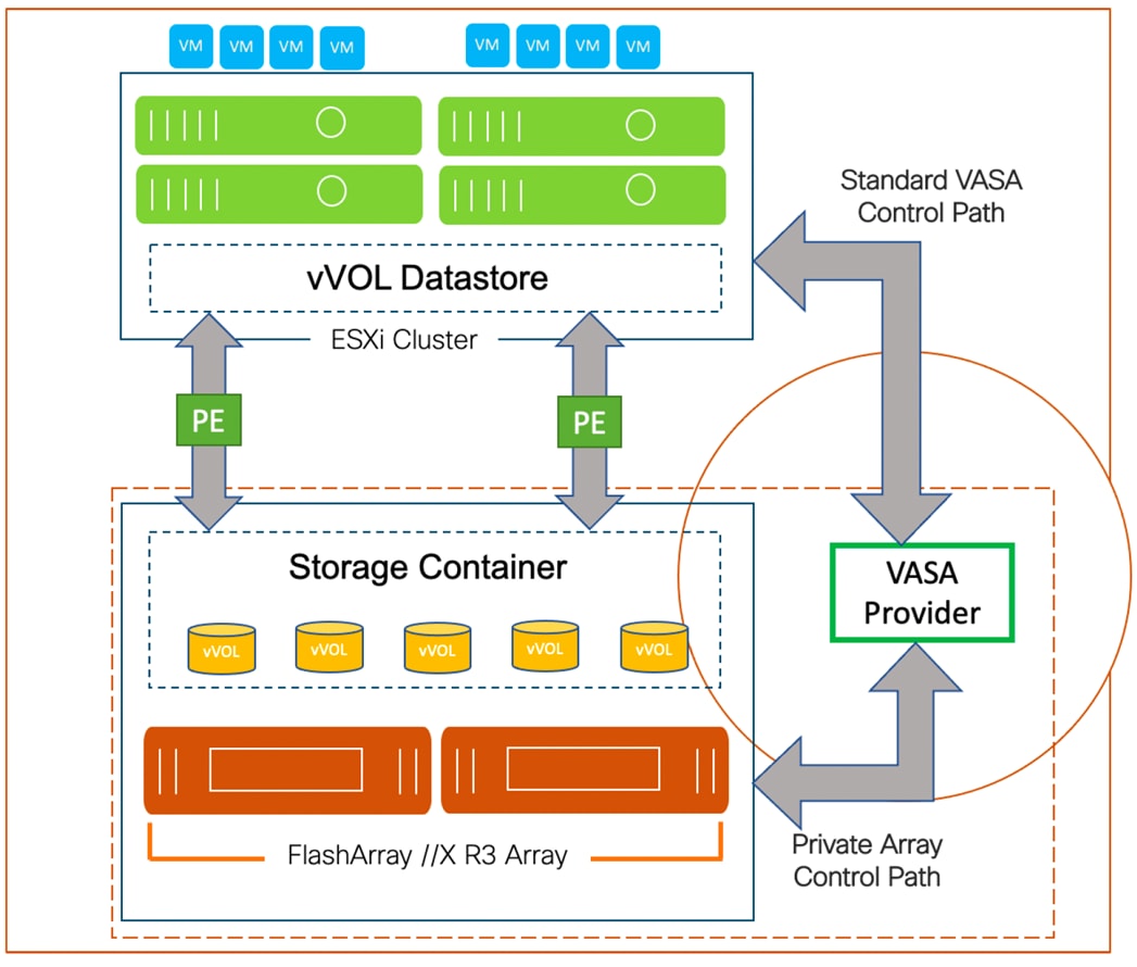
To start using vVOLs with the Pure Storage FlashArray, the FlashArray storage providers must be registered in vCenter Server. The Protocol Endpoint (PE) is then connected to the hostgroup and the vVol datastore is created.
FlashArray Virtual Volumes Considerations
To support multiple VMware vCenters accessing the same FlashArray for vVols, the vCenters should be configured in Enhanced Linked Mode. However, vCenters that are not in Enhanced Linked Mode must use CA-Signed Certificates to use the same FlashArray.
A VM's Config vVol stores the files required to build and manage the VM. Ensure that the Config vVol is part of an existing FlashArray Protection Group. Alternately, if customers are using storage policy that include snapshot or if customers prefer manual snapshots, Config vVol should be part of these snapshots. This will help with the VM recovery process if the VM is deleted.
When a Storage Policy is applied to a vVol VM, the volumes associated with that VM are added to the designated protection group. If replication is part of Storage Policy, the number of VMs using the storage policy as well as the replication groups becomes an important consideration. Many VMs with high change rate could cause replication to miss its schedule due to increased replication bandwidth and time needed to complete the scheduled snapshot. Pure Storage recommends vVol VMs with Storage Policies applied to be balanced between protection groups. To understand FlashArray limits on volume connections per host, volume count and snapshot Count, review the following document: https://support.purestorage.com/FlashArray/PurityFA/General_Troubleshooting/Pure_Storage_FlashArray_Limits.
Pure Storage FlashArray Best Practices for vVols
Along with the above Pure Storage vVol considerations, following best practices should be considered during implementation of vVols:
● Create a Local FlashArray Array-Admin user to register the storage provider instead of using the local “pure user” account.
● Use the Round Robin pathing policy (default) for the Protocol Endpoint.
● Use the Pure Storage Plugin for the vSphere Client to register the FlashArray storage provider and mount the vVols datastore.
● When registering the storage providers manually, register both VASA providers with CT0.ETH0 and CT1.ETH0. The ETH1 interfaces are supported if a custom certificate is used.
● Manually mounting the vVol datastore requires users to connect the protocol endpoint (PE).
● A single PE utilizing the default device queue depth is sufficient in the design.
● VM Templates associated with the vVol VMs should also be kept on vVols.
● VMDK resizing of VMs that resides on a vVol should be completed from vSphere Client and not from FlashArray GUI.
● ESXi Hosts, vCenter Server and FlashArray should synchronize time to the same NTP Server.
● TCP port 8084 must be open and accessible from vCenter Servers and ESXi hosts to the FlashArray that will be used for vVol.
● vCenter Server should not reside on vVols.
● The FlashArray Protocol Endpoint object 'pure-protocol-endpoint' must exist. The FlashArray admin must not rename, delete, or otherwise edit the default FlashArray Protocol Endpoint.
For more information on vVols best practices, go to: https://support.purestorage.com/Solutions/VMware_Platform_Guide/User_Guides_for_VMware_Solutions/Virtual_Volumes_User_Guide/vVols_User_Guide%3A_Best_Practice_Summary.
In addition to command line interface (CLI) and graphical user interface (GUI) configurations, all FlashStack components support configurations through automation frameworks such as Ansible and Terraform, and so on. The FlashStack solution validation team will share automation modules to configure Cisco Nexus, Cisco UCS, Cisco MDS, Pure Storage FlashArray, VMware ESXi, and VMware vCenter. This community-supported GitHub repository is meant to expedite customer adoption of automation by providing them sample configuration playbooks that can be easily developed or integrated into existing customer automation frameworks.
The repositories are available here: https://github.com/ucs-compute-solutions.
This chapter is organized as follows:
● Set up Cisco UCS Fabric Interconnect for Cisco Intersight Managed Mode
● Derive and Deploy Server Profile from the Cisco Intersight Server Profile Template
● Pure Storage FlashArray – Storage Design
● VMware vSphere – ESXi Design
● Cisco Intersight Integration with VMware vCenter and Pure Storage FlashArray
● Cisco Intersight Integration with Cisco Nexus and Cisco MDS Switches
Cisco Intersight Managed Mode standardizes policy and operation management for Cisco UCS X- and B-Series. The compute nodes configuration uses server profiles defined in Cisco Intersight. These server profiles derive all the server characteristics from various policies and templates. At a high level, configuring Cisco UCS using Intersight Managed Mode consists of the steps shown in Figure 20.
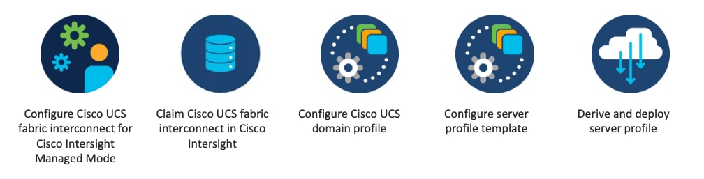
Prior to beginning the installation activities, complete the following necessary tasks and gather the required information. To automate the deployment, the following prerequisites are required:
● The fabric interconnects including required domain policies for the fabric interconnects are configured and deployed.
● Network and FC ports on both fabric interconnects are configured.
● The Cisco UCS X-Series and Cisco UCS B-Series chassis are discovered by Cisco Intersight including all B-Series and X-Series.
● A physical or virtual HTTP server to download all required boot images is configured.
● A VMware vCenter is already available.
● A DHCP, DNS and NTP server is configured and available.
Note: A VMware vSphere cluster requires a shared storage solution. This is not explained in this design guide.
Set up Cisco UCS Fabric Interconnect for Cisco Intersight Managed Mode
Cisco Intersight Managed Mode is a new architecture that manages the Cisco UCS Fabric Interconnected systems through a Redfish-based standard model. You can choose between the native UCSM Managed Mode (UMM) or Cisco Intersight Managed Mode (IMM) for the fabric attached UCS systems during initial setup of the fabric interconnects. You can switch the managed mode at any time by erasing the present configuration; however, the Cisco UCS X-Series system is supported with IMM only.
The initial configuration for the FI can be done by either using the serial console or graphical user interface (GUI) when the FI boots for the first time. This can happen either during factory install, or after the existing configuration is cleared. The configuration wizard enables you to select the management mode and other parameters such as the administrative subnet, gateway, and DNS IP addresses for each Fabric Interconnect.
Claim the Cisco UCS Fabric Interconnect in Cisco Intersight
After setting up the Cisco UCS Fabric Interconnect for Cisco Intersight Managed Mode, FIs can be claimed to a new or an existing Cisco Intersight account. When the Cisco UCS Fabric Interconnect is successfully added to Cisco Intersight, all additional configuration steps are completed in Cisco Intersight.
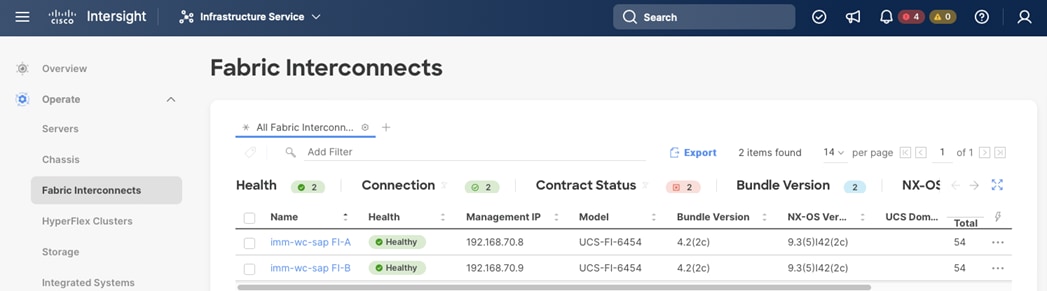
Confirm the managed mode of the fabric interconnects by clicking on the FI name in Cisco Intersight. The managed mode information is displayed in the General tab – Details screen of the Fabric Interconnect overview in Cisco Intersight, shown in Figure 22.
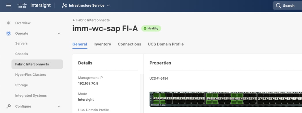
Chassis and Fabric Extenders (FEX) that are connected to a Fabric Interconnect are automatically discovered in Cisco Intersight.
Cisco UCS Chassis Profile
A Cisco UCS Chassis profile configures and associates the chassis policy to a Cisco Intersight Managed Mode (IMM) claimed Cisco UCS chassis. The chassis profile feature is available in Intersight only if customers have installed the Intersight Infrastructure Service Essentials License. The chassis-related policies can be attached to the profile either at the time of creation or later.
The chassis profile in FlashStack is used to set the power policy for the chassis. By default, Cisco UCS X-Series power supplies are configured in GRID mode, but power policy can be utilized to set the power supplies in non-redundant or N+1/N+2 redundant modes as well.
Cisco UCS Domain Profile
A Cisco UCS domain profile configures a fabric interconnect pair through reusable policies, allows configuration of the ports and port channels, and configures the VLANs and VSANs to be used in the network. It defines the characteristics of and configures the ports on the fabric interconnects. One Cisco UCS domain profile can be assigned to one fabric interconnect domain.
Some of the characteristics of the Cisco UCS domain profile in the FlashStack environment are:
● A single domain profile is created for the pair of Cisco UCS fabric interconnects.
● Unique port policies are defined for the two fabric interconnects.
● The VLAN configuration policy is common to the fabric interconnect pair because both fabric interconnects are configured for the same set of VLANs.
● The VSAN configuration policies (FC connectivity option) are unique for the two fabric interconnects because the VSANs are unique.
● The Network Time Protocol (NTP), network connectivity, and system Quality-of-Service (QoS) policies are common to the fabric interconnect pair.
After the Cisco UCS domain profile has been successfully created and deployed, the policies including the port policies are pushed to Cisco UCS Fabric Interconnects. Cisco UCS domain profile can easily be cloned to install additional Cisco UCS servers. When cloning the UCS domain profile, the new UCS domains utilize the existing policies for consistent deployment of additional Cisco UCS servers at scale.
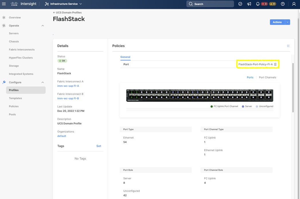
The Cisco UCS X9508 and Cisco UCS 5108 Chassis as well as the Cisco UCS X210c M6 Compute Nodes and Cisco UCS B480 M5 Blade Servers are automatically discovered when the ports are successfully configured using the domain profile. Figure 24, Figure 25, and Figure 26 show both chassis and all servers now part of the UCS domain profile.
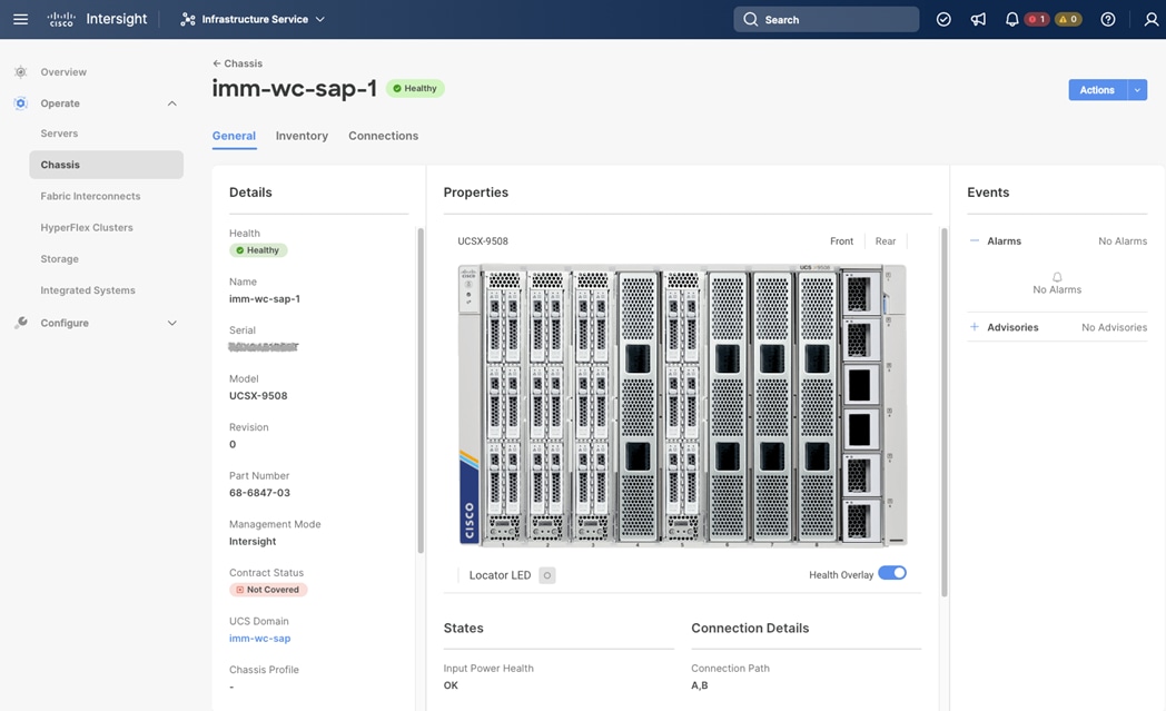
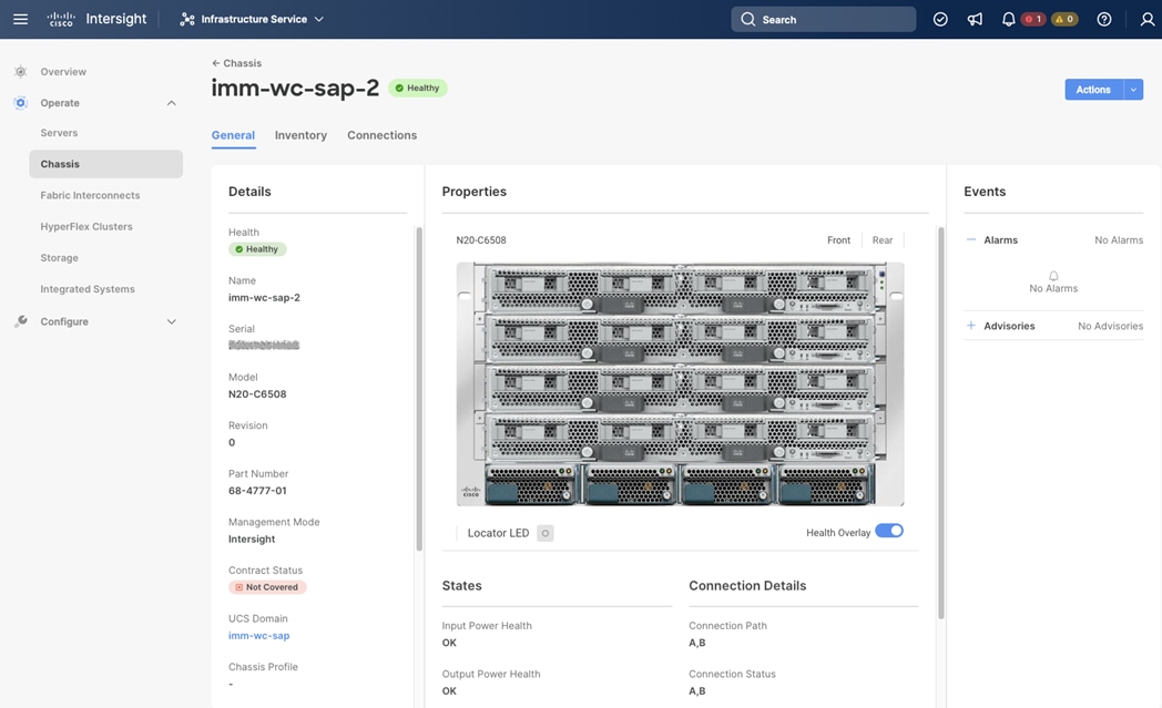
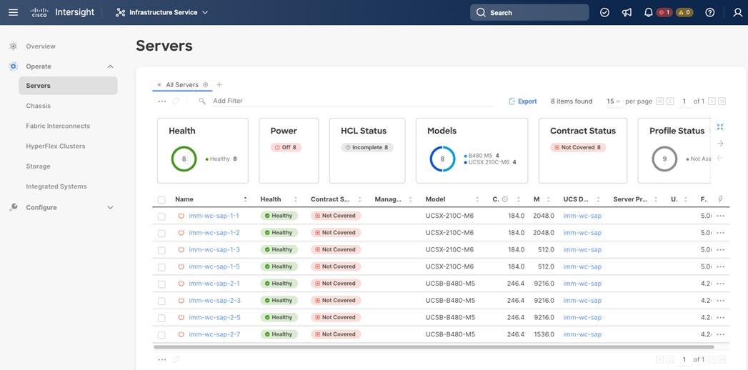
Server Profile Template
A server profile template enables resource management by simplifying policy alignment and server configuration. Create a server profile template either by manually using the server profile template wizard in Cisco Intersight or using Ansible playbooks. The server profile template wizard groups the server policies into the following four categories to provide a quick summary view of the policies that are attached to a profile:
● Compute Configuration - BIOS, boot order, power, and virtual media policies
● Management Configuration – Certificate Management, Integrated Management Controller (IMC), Intelligent Platform Management Interface (IPMI) over LAN, Lightweight Directory Access Protocol (LDAP), local user, Simple Network Management Protocol (SNMP), Secure Shell (SSH), Serial over LAN (SOL), syslog, and virtual Keyboard, Video, and Mouse (KVM) policies
● Storage Configuration – SD Card and local storage policies (not required with FlashStack)
● Network Configuration - LAN connectivity and SAN connectivity policies
◦ The LAN connectivity policy requires the creation of an Ethernet network policy, Ethernet adapter policy, and Ethernet QoS policy.
◦ The SAN connectivity policy requires the creation of a Fibre Channel (FC) network policy, FC adapter policy, and FC QoS policy.
Some of the characteristics of the server profile template for FlashStack are:
● BIOS policy includes various server parameters in accordance with FlashStack best practices.
● Boot order policy defines virtual media (KVM mapper DVD), all SAN paths for Pure Storage FlashArray (FC interfaces), and UEFI Shell.
● IMC access policy defines the management IP address pool for KVM access.
● Local user policy enables KVM-based user access.
● A FC boot from SAN configuration; LAN connectivity policy defines four vNICs — two for management virtual switches (vSwitch0) and two for application VDS — along with various policies and pools.
● SAN connectivity policy creates two virtual host bus adapters (vHBAs) — one for SAN A and one for SAN B — along with various policies and pools.
Derive and Deploy Server Profile from the Cisco Intersight Server Profile Template
The Cisco Intersight server profile allows server configurations to be deployed directly on the compute nodes based on policies defined in the server profile template. After a server profile template has been successfully created, server profiles can be derived from the template and associated with the Cisco UCS X210c M6 Compute Nodes, as shown in Figure 27.
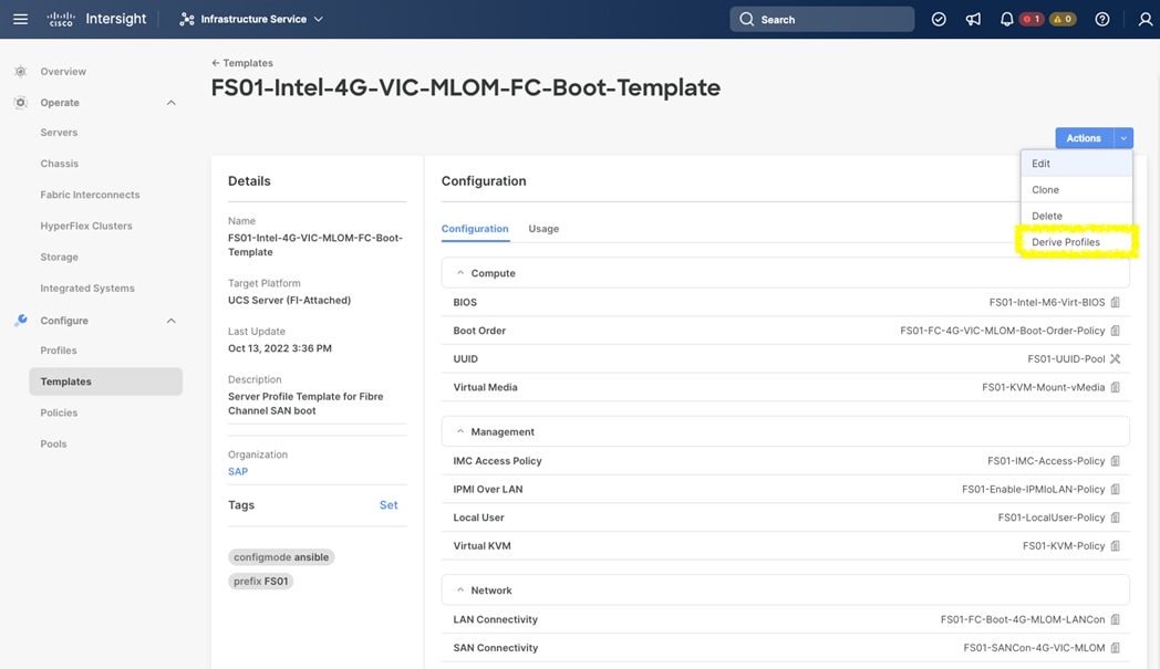
On successful deployment of the server profile, the Cisco UCS X210c M6 Compute Nodes are configured with parameters defined in the server profile and can boot from the storage LUN hosted on Pure Storage FlashArray.
Pure Storage FlashArray – Storage Design
The Pure Storage Purity//FA operating environment automatically handles tuning, encryption, solid-state disk (SSD) wear leveling, and data resiliency (among other operations) at the array level. It is sufficient to name the volume (the target for the data store), enter the size, and attach the volume to the appropriate ESXi host groups.
An important benefit of Pure Storage FlashArray//X is that it enables customers to design their SAP HANA environment data stores with a logical approach rather than constraining them to the limitations of virtual machines per data store. A good practice is to segregate the instance’s SAN boot disks and the SAP HANA disks (data, log, and shared) in separate data stores.
For most use cases a single data store hosting the SAP HANA disks is sufficient to support multiple vHANA instances. The configuration of dedicated data stores for data (higher read performance) and log (higher write performance), though desirable, may not be required because the back-end all-flash array provides a uniform performance-class I/O subsystem, managed by the Purity//FA operating environment.
For SAP HANA TDI scale-up scenarios, the required file system size for data, log, and shared volume depends on the VM memory size:
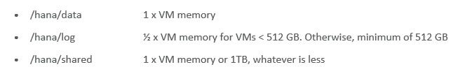
For SAP HANA TDI scale-out scenarios, mount the HANA shared directory as NFS share directly in the SAP HANA VM guest OS using the dedicated network connection to the NFS server environment of the Purity platform.
The setup of the Pure Storage FlashArray//X requires the following items:
● Volumes
◦ ESXi boot LUNs: These LUNs enable ESXi host boot from SAN functionality using Fibre Channel.
◦ The vSphere environment: vSphere uses the infrastructure datastore(s) to store the virtual machines.
◦ SAP HANA volumes in a dedicated datastore
● Hosts
◦ All FlashArray ESXi hosts are defined.
◦ Add every active initiator for a given ESXi host.
● Host groups
◦ All ESXi hosts in a VMware cluster are part of the host group.
◦ Host groups are used to mount VM infrastructure datastores in the VMware environment.
The volumes, interfaces, and VLAN/VSAN details are shown in Figure 28.
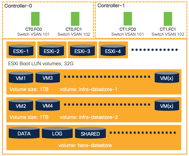
Multiple vNICs (and vHBAs) are created for the ESXi hosts using the Cisco Intersight server profile and are then assigned to specific virtual and distributed switches. The vNIC and vHBA distribution for the ESXi hosts is as follows:
● Two vNICs (one on each fabric) for vSwitch0 to support core services such as management traffic.
● Two vNICs (one on each fabric) for vSphere Virtual Distributed Switch (VDS) to support customer data traffic and vMotion traffic.
● One vHBA each for Fabric-A and Fabric-B for FC stateless boot.
Figure 29 shows the ESXi vNIC configuration in detail.
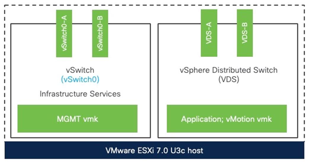
Cisco Intersight Integration with VMware vCenter and Pure Storage FlashArray
Cisco Intersight enhances the ability to provide complete visibility, orchestration, and optimization across all elements of FlashStack datacenter. This empowers customers to make intelligent deployment decisions, easy management, optimize cost and performance and maintain supported configurations for their infrastructure.
Cisco Intersight works with Pure Storage FlashArray and VMware vCenter using third-party device connectors. Since third-party infrastructure does not contain any built-in Intersight device connector, one central Cisco Intersight Assist virtual appliance enables Cisco Intersight to communicate with these non-Cisco devices.
Cisco Intersight integration with VMware vCenter and Pure Storage FlashArray enables customers to perform following tasks right from the Intersight dashboard:
● Monitor the virtualization and storage environment
● Add various dashboard widgets to obtain useful at-a-glance information
● Perform common Virtual Machine tasks such as power on/off, remote console and so on
● Orchestrate virtual and storage environment to perform common configuration tasks
● Extend optimization capability for the entire FlashStack data center
The following sections explain the details of these operations. Since Cisco Intersight is a SaaS platform, further monitoring and orchestration capabilities are constantly being added and delivered seamlessly from the cloud and orchestration tasks and workflows listed below can only provide an in-time snap-shot for reference. Consult the help and search capabilities within Cisco Intersight for the most up-to-date list of capabilities and features.
Licensing Requirement
The integration and view of various Pure Storage FlashArray and VMware vCenter parameters from Cisco Intersight requires the Cisco Intersight Infrastructure Services - Advantage license. The usage of Cisco Intersight orchestration and workflows to provision the storage and virtual environments requires the Cisco Intersight Infrastructure Services - Premier license.
Integrate Cisco Intersight with Pure Storage FlashArray
To integrate Pure Storage FlashArray with the Cisco Intersight platform, you must first deploy a Cisco Intersight Assist virtual appliance and claim Intersight Assist as new target in Cisco Intersight. Afterwards you can claim Pure Storage FlashArray as a target in the Cisco Intersight as shown in Figure 30.
Press the start button to claim the Pure Storage FlashArray//X storage. Provide the Cisco Intersight Assist name, hostname or IP address of the storage, the username with password, and enable the secure connection between Cisco Intersight and the Pure Storage FlashArray//X.
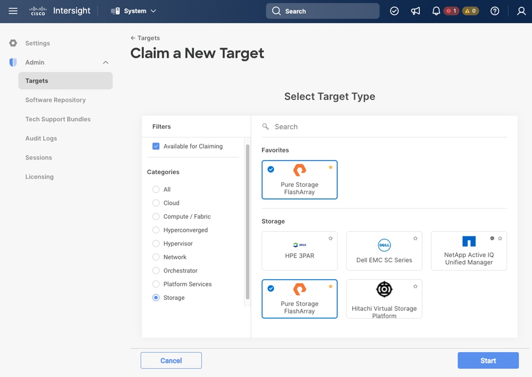
Obtain storage-level information
After the Pure Storage FlashArray//X has been claimed successfully, storage-level information is available in Cisco Intersight.
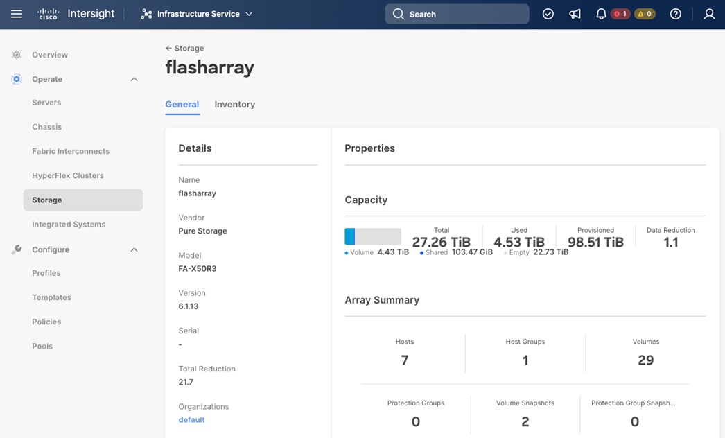
Table 7 lists some of the Pure Storage FlashArray information presented through Cisco Intersight.
Table 7. Pure Storage FlashArray information available in Cisco Intersight
|
|
|
|
| Details |
Name |
Name of the controller |
| Vendor |
Pure Storage |
|
| Model |
Pure Storage FlashArray model information |
|
| Version |
Purity//FA software version |
|
| Serial |
Serial Number |
|
| Total Reduction |
Storage Efficiency |
|
| Properties |
Capacity |
Total, used, provisioned system capacity, and data reduction |
| Array Summary |
|
Summary of hosts, host groups, volumes, protection groups, volume snapshots, and Protection group snapshots |
| Inventory |
Hosts |
Hosts define in the system and associated ports, volumes, and protection of group information |
|
|
Host Groups |
Host groups defined in the system and associated hosts, volumes, and protection groups in the system |
|
|
Volumes |
Configured volumes and volume-specific information such as capacity, data reduction, and so on. |
|
|
Protection Groups |
Protection groups defined in the system and associated targets, members, and so on. |
|
|
Controllers |
FlashArray Controllers and their state, version, and model information |
|
|
Drives |
Storage drive-related information, including type and capacity information |
|
|
Ports |
Information related to physical ports, including Word Wide Port Name (WWPN) and port speed. |
Storage Widgets in the Cisco Intersight Dashboard
Customers can also add the storage dashboard widgets to Cisco Intersight for viewing Pure Storage FlashArray at a glance, as shown in Figure 32.
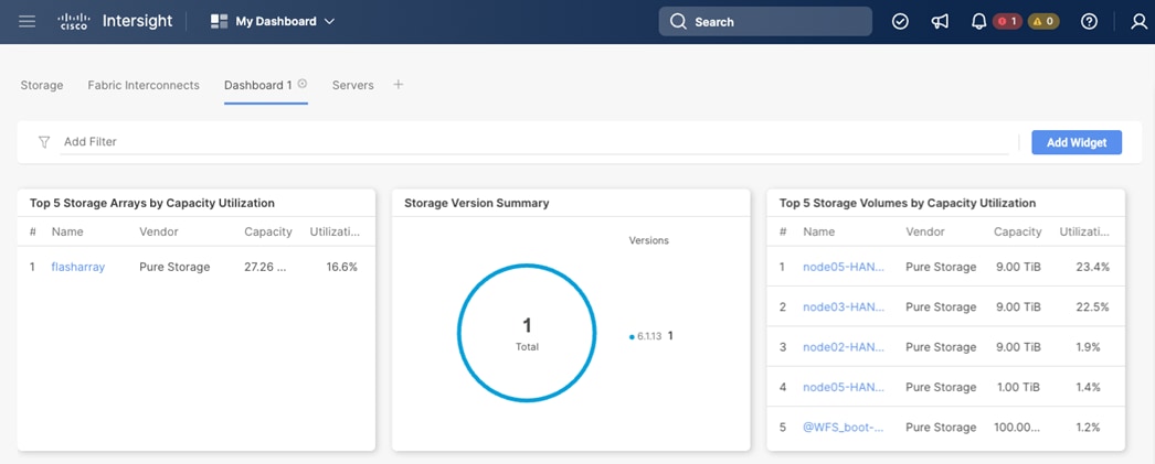
These storage widgets provide useful information such as:
● Storage versions summary, providing information about the software version and the number of storage systems running that version
● Top 5 storage arrays by capacity utilization
● Top 5 storage volumes by capacity utilization
Cisco Intersight Orchestrator – Pure Storage FlashArray
Cisco Intersight Orchestrator provides various workflows that can be used to automate storage provisioning. Some of the sample storage workflows available for Pure Storage FlashArray are listed in Table 8.
Table 8. Some Pure Storage FlashArray workflows in Cisco Intersight Orchestrator
| Workflow |
Description |
| New Storage Host |
Create a new storage host. If host group is provided as input, then the host is added to the host group. |
| New Storage Host Group |
Create a new storage host group. If hosts are provided as inputs, the workflow will add the hosts to the host group. |
| New Hypervisor Datastore |
Create a VMFS or an NFS datastore on VMware ESXi. For VMFS, the storage volume information must be provided. |
| Update Storage Host |
Update the storage host details. If the inputs for a task are provided then the task is run, else it is skipped. |
| Update VMFS datastore |
Expand a datastore on the hypervisor manager by extending the backing storage volume to specified capacity, and then grow the data store to utilize the additional capacity. |
| Remove Storage Host |
Remove a storage host. If a host group name is provided as input, the workflow will also remove the host from the host group. |
| Remove Storage Host Group |
Remove a storage host group. If hosts are provided as input, the workflow will remove the hosts from the host group. |
| Remove VMFS datastore |
Remove a VMFS datastore and remove the backing volume from the storage device. |
In addition to the above workflows, Cisco Intersight Orchestrator also provides many storage and virtualization tasks for customers to create custom workflow based on their specific needs.
Integrate Cisco Intersight with VMware vCenter
Intersight Virtualization Service (IVS) is a fully curated, lightweight, multi-cloud management platform providing a unified approach to virtualization infrastructure management across the public and private clouds. Integrate VMware vCenter with Cisco Intersight and claim it as a target using Cisco Intersight Assist Virtual Appliance, as shown in Figure 33.
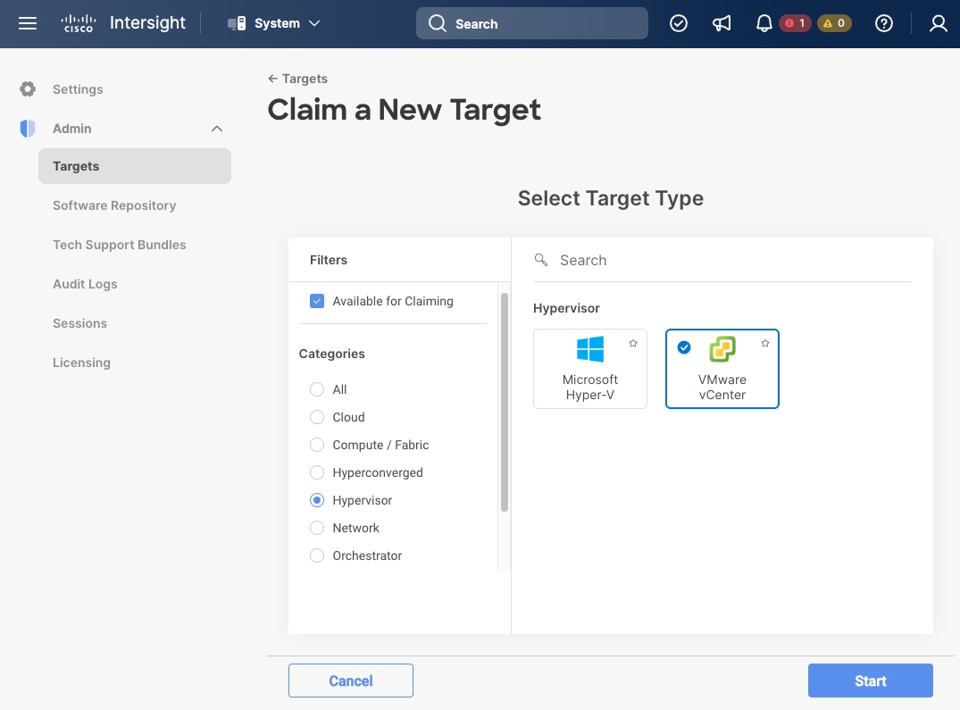
The Intersight Virtualization Service provides the following management features:
● Securely connects to the private and public clouds to gain visibility into virtualization inventory.
● View detailed virtualization infrastructure details for VMware targets.
● Performs virtual machine day-2 operations including power actions (Start, Stop, Soft Stop, Reset, Restart, Terminate), Launch VM Console (VMware), Resize (AWS).
● Tag virtualization infrastructure across multiple clouds.
Obtain Hypervisor-level information
After successfully claiming the VMware vCenter as a target, customers can view hypervisor-level information in Cisco Intersight including hosts, VMs, clusters, datastores, and so on.
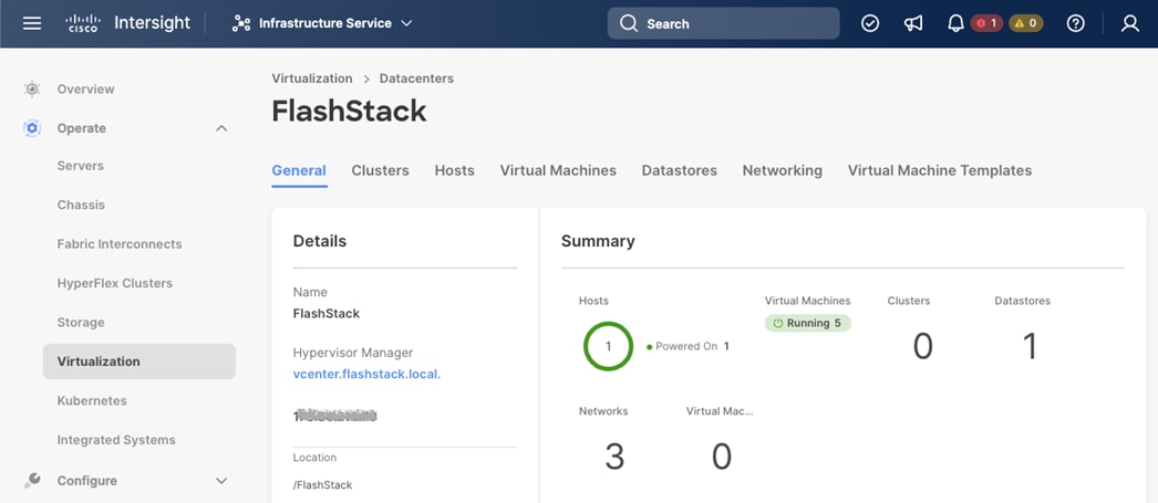
The Virtual Machine page contains the following tabs:
● Virtual Machines — This is the default tab for Intersight Virtualization Service. The tab provides a normalized view of virtualization inventory across the hybrid cloud and enables you to initiate operations on virtual machines.
● Datacenters — This VMware environment tab displays information on the datacenters for all the VMware accounts that you claimed in Intersight.
● Clusters — This tab displays information on the clusters in VMware environments.
● Hosts — This tab displays information on hosts in VMware environments.
● Virtual Machine Templates — This tab displays VMware environment information on the virtual machine templates created by administrators.
● Datastores — This tab displays VMware environment information on datastores that exist within a data center.
● Datastore Clusters — This tab displays VMware environment information on datastore clusters that contain datastores.
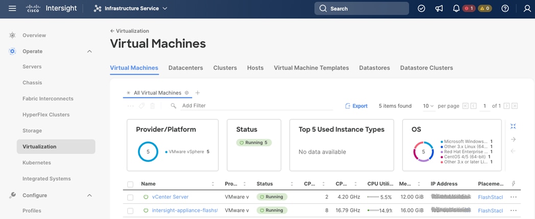
Cisco Intersight Orchestrator - VMware vCenter
Cisco Intersight Orchestrator provides various workflows that can be used and edited to manage VMs and hypervisor provisioning. The workflows available for VMware vCenter are captured in Figure 36.
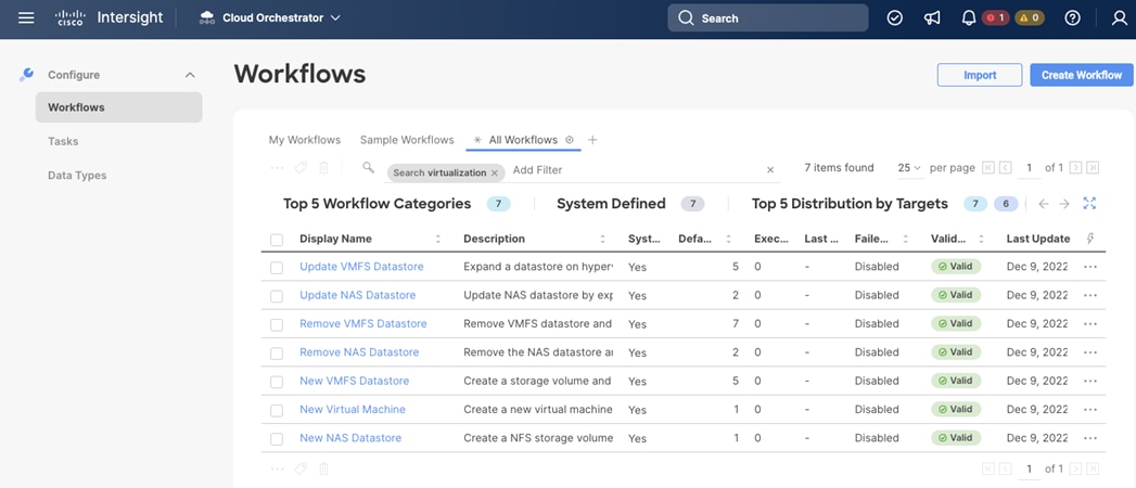
In addition to the above workflows, Cisco Intersight Orchestrator provides many tasks for customers to create custom workflows depending on their specific requirements. A sample subset of the tasks for virtualization workflows shows Figure 37.
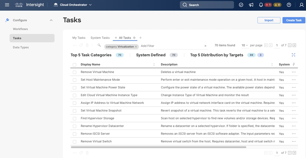
Cisco Intersight Integration with Cisco Nexus and Cisco MDS Switches
With the same Cisco Intersight Assist virtual appliance it is possible to add additional endpoint targets, such as Cisco Nexus and Cisco MDS switches as well as the Cisco Nexus Dashboard.
The NX-API CLI is an RPC-style API, taking and executing CLI commands and is an enhancement to the Cisco NX-OS CLI system. Based on HTPP or HTTPS protocols as common other Representational State Transfer (REST) API frameworks, it allows programmatic access to a Cisco Nexus or MDS switch.
Enable the nxapi feature before claiming the switches as new targets:
switch# configure terminal
switch(config)# feature nxapi
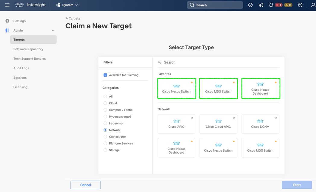
Obtain Data Center Network Information
After successfully claiming the Cisco Nexus and MDS switches as targets, customers can view their Ethernet and SAN details in Cisco Intersight including physical and logical inventory.
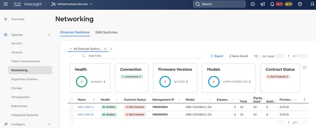
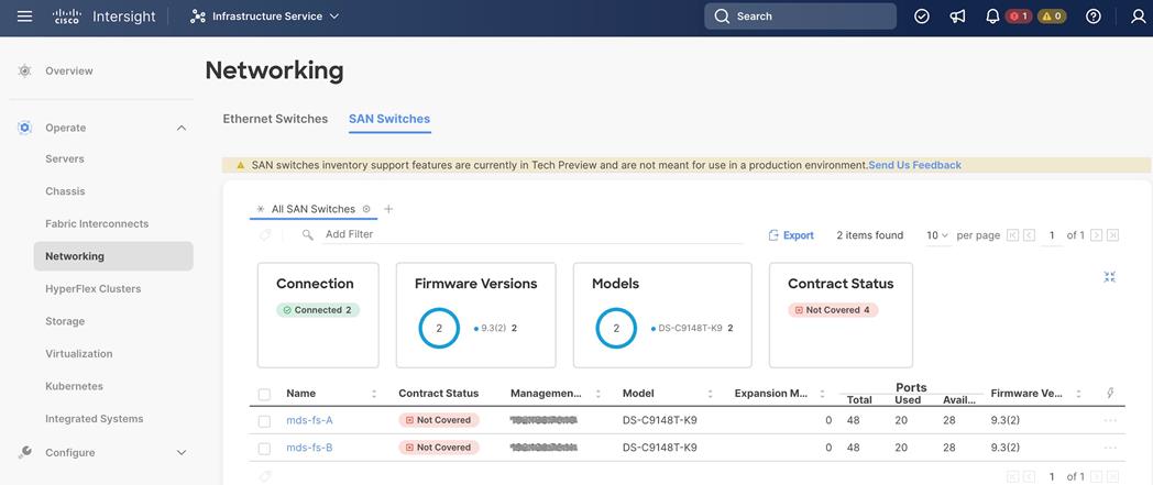
The Cisco Intersight Orchestrator currently provides a total of 53 tasks for the Cisco Nexus and MDS switches to create custom workflows based on specific needs.
Validation
● Functional validation – physical and logical setup validation
● Feature verification – feature verification for FlashStack design
● Availability testing – link and device redundancy and high availability testing
● Infrastructure as a code validation – verify automation and orchestration of solution components
● SAP HANA installation and validation – verify key performance indicator (KPI) metrics with the SAP HANA hardware and cloud measurement tool (HCMT)
The goal of solution validation is to test functional aspects of the design and unless explicitly called out, the performance and scalability is not covered during solution validation. However, limited load is always generated using tools such as HCMT, IOMeter and/or iPerf to help verify the test setup. Some of the examples of the types of tests executed include:
● Verification of features configured on various FlashStack components
● Powering off and rebooting redundant devices and removing redundant links to verify high availability
● Failure and recovery of vCenter and ESXi hosts in a cluster
● Failure and recovery of storage access paths across FlashArray controllers, MDS and Nexus switches, and fabric interconnects
● Server Profile migration between compute nodes
● Load generation using SAP HANA VMs hosted on FlashStack components and path validation
As part of the validation effort, the solution validation team identifies the problems, works with the appropriate development teams to fix the problem, and provides work arounds, as necessary.
The FlashStack solution is a validated approach for deploying Cisco and Pure Storage technologies and products for building shared private and public cloud infrastructure. The best-in-class storage, server and networking components serve as the foundation for a variety of workloads not limited to SAP HANA TDI. The introduction of the Cisco UCS X-Series modular platform extends the FlashStack solution and allows customers to manage and orchestrate the current and next-generation Cisco UCS platform from the cloud using Cisco Intersight.
In addition to the Cisco UCS X-Series hardware and software innovations, the integration of the Cisco Intersight cloud platform with VMware vCenter and Pure Storage FlashArray delivers monitoring, orchestration, and workload optimization capabilities for the different layers (including virtualization and storage) of the FlashStack infrastructure. The modular nature of Cisco Intersight provides an easy upgrade path to additional services, such as workload optimization and Kubernetes.
The FlashStack solution with Cisco UCS X-Series and Cisco Intersight provides the following advantages over alternative solutions:
● A single platform built from unified compute, fabric, and storage technologies, allowing you to scale to large-scale data centers without architectural changes
● Simpler and programmable infrastructure
● Centralized, simplified management of all infrastructure resources, including the Pure Storage FlashArray and VMware vCenter by Cisco Intersight
● Power and cooling innovations with Cisco UCS X-Series and better airflow
● Fabric innovations for heterogeneous compute and memory composability
● Innovative cloud operations providing continuous feature delivery
● Future-ready design built for investment protection
● Common OS and management tools ease network implementation, maintenance, and troubleshooting by relying on the same skill set across SAN, LAN, and computing environments.
● Nexus Dashboard Fabric Controller provides visibility into the network, servers, and storage resources and helps to provide full control of application SLAs and metrics beyond host and virtual machine monitoring.
● Smart Zoning reduces the need to implement and maintain large zone databases and eases management and implementation tasks.
● Organizations can interact with a single vendor when troubleshooting problems across computing, storage, and networking environments.
Joerg Wolters, Technical Marketing Engineer, Cisco Product Group – UCS and SAP solutions, Cisco Systems GmbH
Joerg has over nine years of experience at Cisco with data center, enterprise and service provider solution architectures and 20 years of SAP basis experience from operations, advanced services, performance tuning and SAP sizing. As a technical leader in Cisco CX support, Joerg helped many customers with support of their SAP HANA solutions leading and consulting the SAP HANA solution support teams. As a technical marketing engineer at the Cisco Product and Cisco UCS solutions group, Joerg focuses on network, compute, virtualization, storage, and orchestration aspects of various compute stacks.
Acknowledgements
For their support and contribution to the design, validation, and creation of this Cisco Validated Design, the authors would like to thank:
● Paniraja Koppa, Technical Marketing Engineer, Cisco Systems, Inc.
● Haseeb Niazi, Principal Technical Marketing Engineer, Cisco Systems, Inc.
● Joe Houghes, Senior Solution Architect, Pure Storage, Inc.
● Craig Waters, Technical Director, Pure Storage, Inc.
This appendix is organized as follows:
● Appendix B - References Used in this Guide
● Appendix E - Recommended for You
● Red Hat Ansible Automation Platform: https://www.redhat.com/en/technologies/management/ansible
● GitHub repository for solution deployment: https://github.com/ucs-compute-solutions/FlashStack_IMM_Ansible
Appendix B – References Used in this Guide
Compute
● Cisco Intersight Managed Mode Configuration Guide: https://www.intersight.com/help/saas/resources/cisco_intersight_managed_mode_configuration#introduction
● Cisco UCS B-Series Blade Server: https://www.cisco.com/site/us/en/products/computing/servers-unified-computing-systems/ucs-b-series-blade-servers/index.html
● Cisco UCS X-Series Modular System: https://www.cisco.com/site/us/en/products/computing/servers-unified-computing-systems/ucs-x-series-modular-systems/index.html
● Cisco UCS 6454 Fabric Interconnect: https://www.cisco.com/c/en/us/products/collateral/servers-unified-computing/datasheet-c78-741116.html
● Cisco Intersight Help Center: https://www.intersight.com/help/saas
Network
● Cisco Nexus 9000 Series Switches: https://www.cisco.com/site/us/en/products/networking/cloud-networking-switches/nexus-9000-switches/index.html
● Cisco Nexus 9000 Series NX-OS Programmability Guide, Release 9.3(x): https://www.cisco.com/c/en/us/td/docs/switches/datacenter/nexus9000/sw/93x/progammability/guide/b-cisco-nexus-9000-series-nx-os-programmability-guide-93x.html
● Cisco MDS Switches: https://www.cisco.com/site/us/en/products/networking/cloud-networking-switches/storage-area-networking/index.html
● Cisco UCS and MDS Better Together White Paper: https://www.cisco.com/c/en/us/products/collateral/storage-networking/mds-9700-series-multilayer-directors/cisco-ucs-mds.html
● Cisco MDS 9000 Series Programmability Guide, Release 9.x: https://www.cisco.com/c/en/us/td/docs/dcn/mds9000/sw/9x/programmability/cisco-mds-9000-nx-os-programmability-guide-9x.html
Storage
● Pure Storage FlashArray//X: https://www.purestorage.com/products/nvme/flasharray-x.html
● Pure Storage FlashArray//XL: https://www.purestorage.com/products/nvme/flasharray-xl.html
Virtualization
● Pure Storage FlashArray VMware Best Practices: https://support.purestorage.com/Solutions/VMware_Platform_Guide/User_Guides_for_VMware_Solutions/FlashArray_VMware_Best_Practices_User_Guide/hhhWeb_Guide%3A_FlashArray_VMware_Best_Practices
● SAP HANA on VMware vSphere Best Practices and Reference Architecture Guide: https://core.vmware.com/resource/sap-hana-vmware-vsphere-best-practices-and-reference-architecture-guide#abstract
● SAP HANA on VMware vSphere: https://wiki.scn.sap.com/wiki/plugins/servlet/mobile?contentId=449288968#content/view/449288968
● VMware vCenter Server: http://www.vmware.com/products/vcenter-server/overview.html
● VMware vSphere: https://www.vmware.com/products/vsphere
SAP
Note: Requires an SAP Universal Login
● SAP Note 2161991 – VMware vSphere configuration guidelines: https://launchpad.support.sap.com/#/notes/2161991
● SAP Note 2235581 – SAP HANA: Supported Operating Systems: https://launchpad.support.sap.com/#/notes/2235581
● SAP Note 2937606 – SAP HANA on VMware vSphere 7.0 in production: https://launchpad.support.sap.com/#/notes/2937606
Interoperability Matrix
● Cisco UCS Hardware and Software Compatibility: https://ucshcltool.cloudapps.cisco.com/public/
● Interoperability Matrix for Cisco Nexus and MDS 9000 products: https://www.cisco.com/c/en/us/td/docs/switches/datacenter/mds9000/interoperability/matrix/intmatrx.html
● Pure Storage Interoperability Matrix (Requires a Pure Storage support login): https://support.purestorage.com/FlashArray/Getting_Started/Compatibility_Matrix
● Pure Storage FlashStack Compatibility Matrix (requires a Pure Storage support login): https://support.purestorage.com/FlashStack/Product_Information/FlashStack_Compatibility_Matrix
● SAP HANA supported server and storage systems: https://www.sap.com/dmc/exp/2014-09-02-hana-hardware/enEN/#/solutions?filters=ve:1;ve:18
● VMware Compatibility Guide: https://www.vmware.com/resources/compatibility/search.php?deviceCategory=server&details=1&partner=146&releases=578&cpuSeries=128,147,129,146,130,148&page=1&display_interval=10&sortColumn=Partner&sortOrder=Asc
Appendix C – Glossary
This glossary addresses some terms used in this document, for the purposes of aiding understanding. This is not a complete list of all multicloud terminology. Some Cisco product links are supplied here also, where considered useful for the purposes of clarity, but this is by no means intended to be a complete list of all applicable Cisco products.
| aaS/XaaS (IT capability provided as a Service) |
Some IT capability, X, provided as a service (XaaS). Some benefits are:
● The provider manages the design, implementation, deployment, upgrades, resiliency, scalability, and overall delivery of the service and the infrastructure that supports it.
● There are very low barriers to entry, so that services can be quickly adopted and dropped in response to business demand, without the penalty of inefficiently utilized CapEx.
● The service charge is an IT OpEx cost (pay-as-you-go), whereas the CapEx and the service infrastructure is the responsibility of the provider.
● Costs are commensurate in terms of to usage and hence more easily controlled with respect to business demand and outcomes.
Such services are typically implemented as “microservices,” which are accessed via REST APIs. This architectural style supports composition of service components into systems. Access to and management of aaS assets is via a web GUI and/or APIs, such that Infrastructure-as-code (IaC) techniques can be used for automation, for example, Ansible and Terraform. The provider can be any entity capable of implementing an aaS “cloud-native” architecture. The cloud-native architecture concept is well-documented and supported by open-source software and a rich ecosystem of services such as training and consultancy. The provider can be an internal IT department or any of many third-party companies using and supporting the same open-source platforms. Service access control, integrated with corporate IAM, can be mapped to specific users and business activities, enabling consistent policy controls across services, wherever they are delivered from. |
| Ansible |
An infrastructure automation tool, used to implement processes for instantiating and configuring IT service components, such as VMs on an IaaS platform. Supports the consistent execution of processes defined in YAML “playbooks” at scale, across multiple targets. Because the Ansible artefacts (playbooks) are text-based, they can be stored in a Source Code Management (SCM) system, such as GitHub. This allows for software development like processes to be applied to infrastructure automation, such as, Infrastructure-as-code (see IaC below). |
| Co-located data center |
“A colocation center (CoLo)…is a type of data center where equipment, space, and bandwidth are available for rental to retail customers. Colocation facilities provide space, power, cooling, and physical security for the server, storage, and networking equipment of other firms and also connect them to a variety of telecommunications and network service providers with a minimum of cost and complexity.” |
| DevOps |
The underlying principle of DevOps is that the application development and operations teams should work closely together, ideally within the context of a toolchain that automates the stages of development, test, deployment, monitoring, and issue handling. DevOps is closely aligned with IaC, continuous integration and deployment (CI/CD), and Agile software development practices. |
| IaaS (Infrastructure as-a-Service) |
Infrastructure components provided aaS, located in data centers operated by a provider, typically accessed over the public Internet. IaaS provides a base platform for the deployment of workloads, typically with containers and Kubernetes (K8s). |
| IaC (Infrastructure as-Code) |
Given the ability to automate aaS via APIs, the implementation of the automation is typically via Python code, Ansible playbooks, and similar. These automation artefacts are programming code that define how the services are consumed. As such, they can be subject to the same code management and software development regimes as any other body of code. This means that infrastructure automation can be subject to all of the quality and consistency benefits, CI/CD, traceability, automated testing, compliance checking, and so on, that could be applied to any coding project. |
| IAM (Identity and Access Management) |
IAM is the means to control access to IT resources so that only those explicitly authorized to access given resources can do so. IAM is an essential foundation to a secure multicloud environment. |
| Intersight |
Cisco Intersight™ is a Software-as-a-Service (SaaS) infrastructure lifecycle management platform that delivers simplified configuration, deployment, maintenance, and support. https://www.cisco.com/c/en/us/products/servers-unified-computing/intersight/index.html |
| NX-OS |
Cisco NX-OS is an extensible, open, and programmable network operating system for the next-generation data centers and cloud networks. It runs on Cisco Nexus data center and Cisco MDS storage networking switches. https://www.cisco.com/c/en/us/products/ios-nx-os-software/nx-os/index.html |
| PaaS (Platform-as-a-Service) |
PaaS is a layer of value-add services, typically for application development, deployment, monitoring, and general lifecycle management. The use of IaC with IaaS and PaaS is very closely associated with DevOps practices. |
| Private on-premises data center |
A data center infrastructure housed within an environment owned by a given enterprise is distinguished from other forms of data center, with the implication that the private data center is more secure, given that access is restricted to those authorized by the enterprise. Thus, circumstances can arise where very sensitive IT assets are only deployed in a private data center, in contrast to using public IaaS. For many intents and purposes, the underlying technology can be identical, allowing for hybrid deployments where some IT assets are privately deployed but also accessible to other assets in public IaaS. IAM, VPNs, firewalls, and similar are key technologies needed to underpin the security of such an arrangement. |
| REST API |
Representational State Transfer (REST) APIs is a generic term for APIs accessed over HTTP(S), typically transporting data encoded in JSON or XML. REST APIs have the advantage that they support distributed systems, communicating over HTTP, which is a well-understood protocol from a security management perspective. REST APIs are another element of a cloud-native applications architecture, alongside microservices. https://en.wikipedia.org/wiki/Representational_state_transfer |
| SaaS (Software-as-a-Service) |
End-user applications provided “aaS” over the public Internet, with the underlying software systems and infrastructure owned and managed by the provider. |
| SAML (Security Assertion Markup Language) |
Used in the context of Single-Sign-On (SSO) for exchanging authentication and authorization data between an identity provider, typically an IAM system, and a service provider (some form of SaaS). The SAML protocol exchanges XML documents that contain security assertions used by the aaS for access control decisions. https://en.wikipedia.org/wiki/Security_Assertion_Markup_Language |
Appendix D – Acronyms
API—Application Programming Interface
CPU—Central Processing Unit
CVD—Cisco Validated Design
DC—Data Center
DHCP—Dynamic Host Configuration Protocol
DMZ—Demilitarized Zone (firewall/networking construct)
DNS—Domain Name System
EID—Endpoint Identifier
GbE—Gigabit Ethernet
Gbit/s—Gigabits Per Second (interface/port speed reference)
HA—High-Availability
IP—Internet Protocol
LACP—Link Aggregation Control Protocol
LAN—Local Area Network
L2 VNI—Layer 2 Virtual Network Identifier; as used in SD-Access Fabric, a VLAN.
L3 VNI— Layer 3 Virtual Network Identifier; as used in SD-Access Fabric, a VRF.
MAC—Media Access Control Address (OSI Layer 2 Address)
MTU—Maximum Transmission Unit
NFV—Network Functions Virtualization
OSI—Open Systems Interconnection model
QoS—Quality of Service
REST—Representational State Transfer
RTT—Round-Trip Time
SD—Software-Defined
SFP—Small Form-Factor Pluggable (1 GbE transceiver)
SFP+— Small Form-Factor Pluggable (10 GbE transceiver)
SNMP—Simple Network Management Protocol
STP—Spanning-tree protocol
SVI—Switched Virtual Interface
Syslog—System Logging Protocol
TCP—Transmission Control Protocol (OSI Layer 4)
UCS— Cisco Unified Computing System
VLAN—Virtual Local Area Network
VM—Virtual Machine
VNI—Virtual Network Identifier (VXLAN)
vPC—virtual Port Channel (Cisco Nexus)
VRF—Virtual Routing and Forwarding
VXLAN—Virtual Extensible LAN
Appendix E – Recommended for You
FlashStack Virtual Server Infrastructure for End-to-End 100 GB Design Guide: https://www.cisco.com/c/en/us/td/docs/unified_computing/ucs/UCS_CVDs/flashstack_vsi_ucs_xseries_5gen_design.html
FlashStack Virtual Server Infrastructure with End-to-End 100G, Cisco Intersight Managed UCS X-Series, and Pure Storage FlashArray//XL: https://www.cisco.com/c/en/us/td/docs/unified_computing/ucs/UCS_CVDs/flashstack_ucs_xseries_e2e_5gen.html
For comments and suggestions about this guide and related guides, join the discussion on Cisco Community at https://cs.co/en-cvds.
CVD Program
ALL DESIGNS, SPECIFICATIONS, STATEMENTS, INFORMATION, AND RECOMMENDATIONS (COLLECTIVELY, "DE-SIGNS") IN THIS MANUAL ARE PRESENTED "AS IS," WITH ALL FAULTS. CISCO AND ITS SUPPLIERS DISCLAIM ALL WAR-RANTIES, INCLUDING, WITHOUT LIMITATION, THE WARRANTY OF MERCHANTABILITY, FITNESS FOR A PARTICULAR PURPOSE AND NONINFRINGEMENT OR ARISING FROM A COURSE OF DEALING, USAGE, OR TRADE PRACTICE. IN NO EVENT SHALL CISCO OR ITS SUPPLIERS BE LIABLE FOR ANY INDIRECT, SPECIAL, CONSEQUENTIAL, OR INCIDENTAL DAMAGES, INCLUDING, WITHOUT LIMITATION, LOST PROFITS OR LOSS OR DAMAGE TO DATA ARISING OUT OF THE USE OR INABILITY TO USE THE DESIGNS, EVEN IF CISCO OR ITS SUPPLIERS HAVE BEEN ADVISED OF THE POSSIBILITY OF SUCH DAMAGES.
THE DESIGNS ARE SUBJECT TO CHANGE WITHOUT NOTICE. USERS ARE SOLELY RESPONSIBLE FOR THEIR APPLICA-TION OF THE DESIGNS. THE DESIGNS DO NOT CONSTITUTE THE TECHNICAL OR OTHER PROFESSIONAL ADVICE OF CISCO, ITS SUPPLIERS OR PARTNERS. USERS SHOULD CONSULT THEIR OWN TECHNICAL ADVISORS BEFORE IMPLE-MENTING THE DESIGNS. RESULTS MAY VARY DEPENDING ON FACTORS NOT TESTED BY CISCO.
CCDE, CCENT, Cisco Eos, Cisco Lumin, Cisco Nexus, Cisco StadiumVision, Cisco TelePresence, Cisco WebEx, the Cisco logo, DCE, and Welcome to the Human Network are trademarks; Changing the Way We Work, Live, Play, and Learn and Cisco Store are service marks; and Access Registrar, Aironet, AsyncOS, Bringing the Meeting To You, Catalyst, CCDA, CCDP, CCIE, CCIP, CCNA, CCNP, CCSP, CCVP, Cisco, the Cisco Certified Internetwork Expert logo, Cisco IOS, Cisco Press, Cisco Systems, Cisco Systems Capital, the Cisco Systems logo, Cisco Unified Computing System (Cisco UCS), Cisco UCS B-Series Blade Servers, Cisco UCS C-Series Rack Servers, Cisco UCS S-Series Storage Servers, Cisco UCS Manager, Cisco UCS Management Software, Cisco Unified Fabric, Cisco Application Centric Infrastructure, Cisco Nexus 9000 Series, Cisco Nexus 7000 Series. Cisco Prime Data Center Network Manager, Cisco NX-OS Software, Cisco MDS Series, Cisco Unity, Collaboration Without Limitation, EtherFast, EtherSwitch, Event Center, Fast Step, Follow Me Browsing, FormShare, GigaDrive, HomeLink, Internet Quotient, IOS, iPhone, iQuick Study, LightStream, Linksys, MediaTone, MeetingPlace, MeetingPlace Chime Sound, MGX, Networkers, Networking Academy, Network Registrar, PCNow, PIX, PowerPanels, ProConnect, ScriptShare, SenderBase, SMARTnet, Spectrum Expert, StackWise, The Fastest Way to Increase Your Internet Quotient, TransPath, WebEx, and the WebEx logo are registered trade-marks of Cisco Systems, Inc. and/or its affiliates in the United States and certain other countries. (LDW_P5)
All other trademarks mentioned in this document or website are the property of their respective owners. The use of the word partner does not imply a partnership relationship between Cisco and any other company. (0809R)