FlashStack Virtual Server Infrastructure with End-to-End 100G, Cisco Intersight Managed UCS X-Series, and Pure Storage FlashArray//XL
Available Languages
Bias-Free Language
The documentation set for this product strives to use bias-free language. For the purposes of this documentation set, bias-free is defined as language that does not imply discrimination based on age, disability, gender, racial identity, ethnic identity, sexual orientation, socioeconomic status, and intersectionality. Exceptions may be present in the documentation due to language that is hardcoded in the user interfaces of the product software, language used based on RFP documentation, or language that is used by a referenced third-party product. Learn more about how Cisco is using Inclusive Language.
- US/Canada 800-553-2447
- Worldwide Support Phone Numbers
- All Tools
 Feedback
 Feedback
Published: December 2022

![]()
In partnership with:
![]()
About the Cisco Validated Design Program
The Cisco Validated Design (CVD) program consists of systems and solutions designed, tested, and documented to facilitate faster, more reliable, and more predictable customer deployments. For more information, go to:
http://www.cisco.com/go/designzone.
This document explains the deployment details of incorporating the Cisco Unified Computing System™ (Cisco UCS®) X-Series modular platform, Cisco Unified Computing System™ 5th Generation Fabric Technology (5th Generation Fabric Interconnects 6536, 5th Generation Cisco UCS Virtual Interface Card and Cisco UCS 9108-IFM-100G IFM), Pure Storage FlashArray//XL170 and Pure Storage FlashArray//X50 R3 into the FlashStack Virtual Server Infrastructure (VSI) to enable end-to-end 100G Ethernet and 32G Fibre Channel.
Additionally, this FlashStack solution also includes Cisco UCS C225 M6 and C245 M6 Rack servers. The solution is delivered as Infrastructure as Code (IaC) to eliminate error-prone manual tasks, allowing quicker and more consistent solution deployments.
Customers interested in understanding FlashStack design and deployment details, including the configuration of various elements of design and associated best practices, should refer to Cisco Validated Designs for FlashStack at: https://www.cisco.com/c/en/us/solutions/design-zone/data-center-design-guides/data-center-design-guides-all.html - FlashStack.
● Reduced complexity, automatable infrastructure and easily deployed resources
● Robust components capable of supporting high performance and high bandwidth virtualized applications
● Efficiency through optimization of network bandwidth and in-line storage compression with de-duplication
● Risk reduction at each level of the design with resiliency built into each touch point
● Cloud based monitoring, management, and support of your physical and virtual infrastructure
Cisco and Pure Storage have partnered to deliver this Cisco Validated Design, which uses best of breed storage, server, and network components to serve as the foundation for virtualized workloads, enabling efficient architectural designs that can be quickly and confidently deployed.
This document provides deployment details to enable end-to-end 100 Gigabit network connectivity in FlashStack datacenter with Cisco UCS 5th Generation Fabric Technology which includes:
● 5th Generation Fabric Interconnects 6536
● 5th Generation Cisco UCS Virtual Interface Card
● Cisco UCS 9108-IFM-100G IFM
The document discusses FlashStack Virtual Server Infrastructure (VSI) implemented with iSCSI, FC, and NVMe-oF. This infrastructure solution is centered around latest innovations of Cisco UCS including Cisco UCS X210c M6 Compute Node with Cisco VIC 15231 in Cisco UCS X9508 Chassis, 5th Generation Cisco UCS 6536 Fabric Interconnect, Cisco UCS C225 M6 and C245 M6 Rack servers, Cisco Nexus switches, Cisco MDS Multilayer Fabric Switches, and Pure Storage newest addition to the FlashArray family of products FlashArray//XL170 and FlashArray//X50 R3.
Audience
Purpose of this Document
This document highlights new features of the Cisco Intersight platform that enhance the ability to provide visibility and orchestration across all elements of the FlashStack Datacenter.
The manual and automated deployment of the solution are detailed in this Deployment Guide.
What’s New in this Release?
The following design elements distinguish this version of FlashStack VSI solution from previous models:
● Support for End-to-End 100 Gigabit Ethernet and 32 Gigabit Fibre Channel with Cisco UCS 5th Generation Fabric Technology
● Integration of 5th Generation Cisco UCS 6536 Fabric Interconnect which offers line-rate, low-latency, lossless 10/25/40/100 Gigabit Ethernet, Fibre Channel, NVMe over Fabric, and Fibre Channel over Ethernet (FCoE) functions
● Integration with Cisco UCS 9108 100G Intelligent Fabric Module (IFM) which connects the I/O fabric between the 6536 Fabric Interconnect and the Cisco UCS X9508 Chassis
● Integration of the Cisco UCS X-Series with 5th Generation Cisco UCS Virtual Interface Card (VIC) 15231 capable of 2x100-Gbps Ethernet/FCoE
● Integration of Pure Storage FlashArray//XL170 and FlashArray//X50R3 with Purity//FA
● Integration of AMD CPU-based Cisco UCS C225 M6 and Cisco UCS C245 M6 Rack servers with Cisco UCS Virtual Interface Card 1495
● Support for VMware vSphere 7.0 U3
● Integration of the Cisco Intersight platform with Pure Storage FlashArray for storage monitoring and orchestration
● Integration of the Cisco Intersight software with VMware vCenter for interaction, monitoring, and orchestration of the virtual environment
Deployment Hardware and Software
Architecture
The FlashStack VSI with 5th Generation fabric technology and Cisco UCS X-Series enables end-to-end 100 Gigabit Ethernet and 32 Gigabit Fibre channel connectivity. The solution delivers a cloud-managed infrastructure solution on the latest Cisco UCS hardware. VMware vSphere 7.0 U3 hypervisor is installed on the Cisco UCS X210c, and C-Series M6 Compute Nodes configured for stateless compute design using boot from SAN. Pure Storage FlashArray//XL 170 and FlashArray//X50 R3 provides the storage infrastructure required for setting up the VMware environment. The Cisco Intersight cloud-management platform is utilized to configure and manage the infrastructure. The solution requirements and design details are covered in this section.
Requirements
The FlashStack VSI with Cisco UCS X-Series and 5th generation Fabric Technology meets the following general design requirements:
● Resilient design across all layers of the infrastructure with no single point of failure
● Scalable design with the flexibility to add compute and storage capacity or network bandwidth as needed
● Modular design that can be replicated to expand and grow as the needs of the business grow
● Flexible design that can support different models of various components with ease
● Simplified design with ability to integrate and automate with external automation tools
● Cloud-enabled design which can be configured, managed, and orchestrated from the cloud using GUI or APIs
Physical Topology
FlashStack with 5th Generation fabric technology and Cisco UCS X-Series supports both IP-based and Fibre Channel based storage access design. For the IP-based solution, iSCSI configuration on Cisco UCS and Pure Storage FlashArray is utilized to set up storage access including boot from SAN configuration for the compute nodes. For the Fibre Channel designs, Pure Storage FlashArray and Cisco UCS X-Series are connected using Cisco MDS 9132T switches and storage access, including boot from SAN, is provided over the Fibre Channel network. The physical connectivity details for both IP and FC designs are explained in the following sections.
IP-based Storage Access
The physical topology for the IP-based FlashStack is shown in Figure 1.
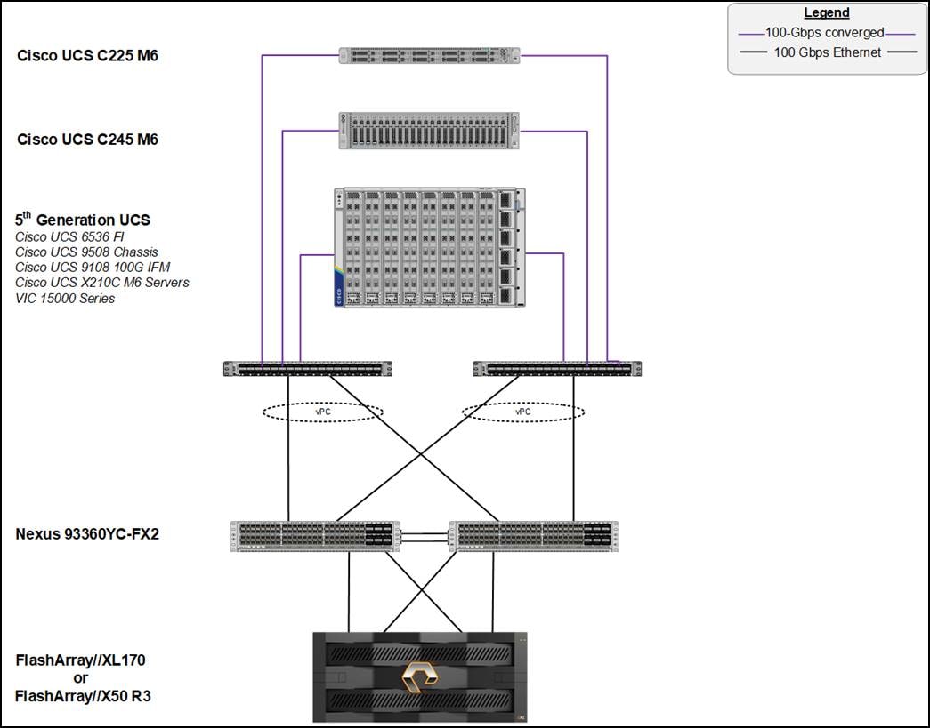
To validate the IP-based storage access in a FlashStack configuration, the components are set up as follows:
● Cisco UCS 6536 Fabric Interconnects provide the chassis and network connectivity.
● The Cisco UCS X9508 Chassis connects to fabric interconnects using Cisco UCS 9108-100G intelligent fabric modules (IFMs), where four 100 Gigabit Ethernet ports are used on each IFM to connect to the appropriate FI. If additional bandwidth is required, all eight 100 Gigabit ports can be utilized.
● Cisco UCS X210c M6 Compute Nodes contain 5th Generation Cisco 15231 virtual interface cards.
● AMD based Cisco UCS C225 M6 Rack Servers with Cisco VIC 1495.
● AMD based Cisco UCS C245 M6 Rack Servers with Cisco VIC 1495.
● Cisco Nexus 93360YC-FX2 Switches in Cisco NX-OS mode provide the switching fabric.
● Cisco UCS 6536 Fabric Interconnect 100-Gigabit Ethernet uplink ports connect to Cisco Nexus 93360YC-FX2 Switches in a Virtual Port Channel (vPC) configuration.
● The Pure Storage FlashArray//XL170 and FlashArray//X50 R3 connects to the Cisco Nexus 93360YC-FX2 switches using four 100-GE ports.
● VMware 7.0 U3 ESXi software is installed on Cisco UCS X210c M6 Compute Nodes to validate the infrastructure.
FC-based Storage Access
Figure 2 illustrates the FlashStack physical topology for FC connectivity.
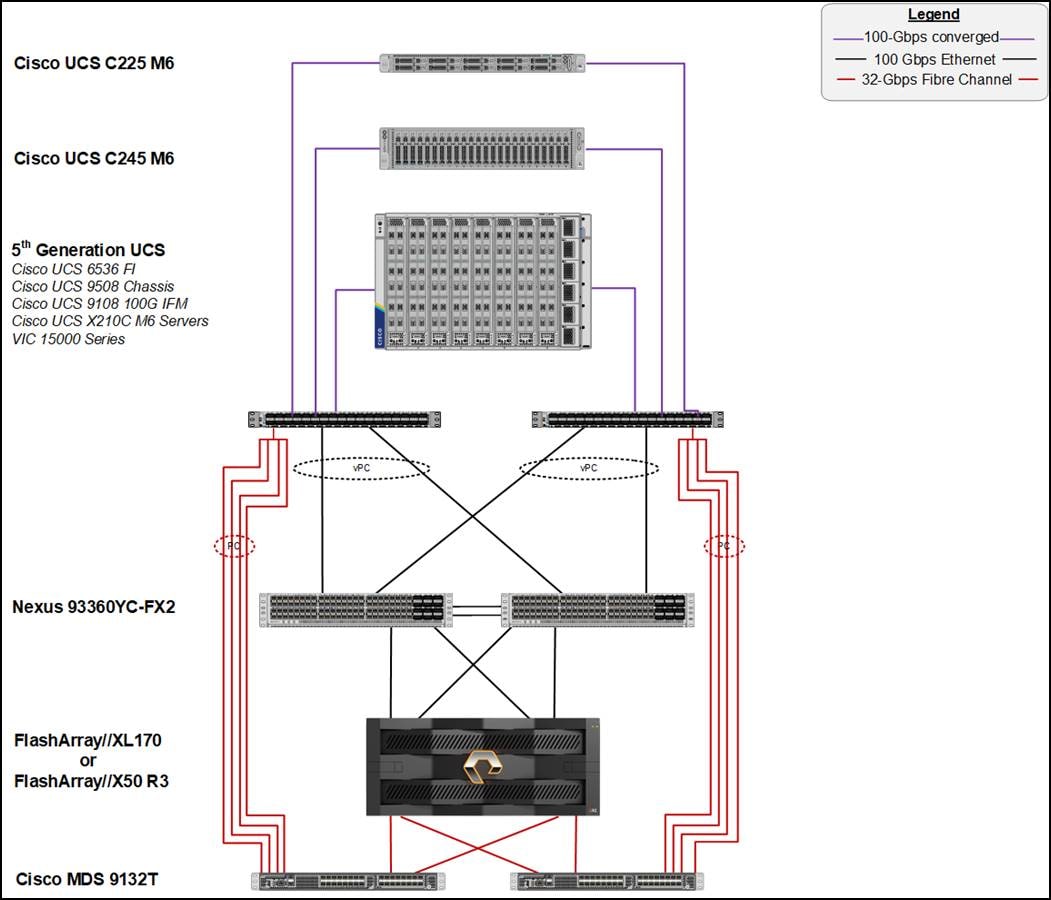
● Cisco UCS 6536 Fabric Interconnects provide the chassis and network connectivity.
● The Cisco UCS X9508 Chassis connects to fabric interconnects using Cisco UCS 9108-100G Intelligent Fabric Modules (IFMs), where four 100 Gigabit Ethernet ports are used on each IFM to connect to the appropriate FI.
● Cisco UCS X210c M6 Compute Nodes contain fifth-generation Cisco UCS 15231 virtual interface cards.
● AMD based Cisco UCS C225 M6 Rack Servers with Cisco VIC 1495.
● AMD based Cisco UCS C245 M6 Rack Servers with Cisco VIC 1495.
● Cisco Nexus switches in Cisco NX-OS mode provide the switching fabric.
● Cisco UCS 6536 Fabric Interconnect 100 Gigabit Ethernet uplink ports connect to Cisco Nexus 93360YC-FX2 Switches in a vPC configuration.
● The Cisco 128G FC QSPF (PID: DS-SFP-4x32G-SW) are used to connect between Cisco UCS 6536 Fabric Interconnects (128G) and Cisco MDS 9132T at 32G speeds using a multi-mode OM4, 8 fiber MPO to LC breakout cable.
● 128 to 32-Gbps breakout Fibre Channel connections configured as a single port channel for SAN connectivity.
● The Pure Storage FlashArray//XL170 and FlashArray//X50 R3 connects to the Cisco MDS 9132T switches using 32-Gbps Fibre Channel connections for SAN connectivity.
● VMware 7.0 U3 ESXi software is installed on Cisco UCS X210c M6 Compute Nodes to validate the infrastructure.
Deployment Hardware and Software
Table 1 lists the hardware and software versions used during solution validation. It is important to note that the validated FlashStack solution explained in this document adheres to Cisco, Pure Storage, and VMware interoperability matrix to determine support for various software and driver versions. Customers should use the same interoperability matrix to determine support for components that are different from the current validated design.
Click the following links for more information:
● Cisco UCS Hardware and Software Interoperability Tool: http://www.cisco.com/web/techdoc/ucs/interoperability/matrix/matrix.html
● Pure Storage Interoperability (note, this interoperability list will require a support login form Pure): https://support.purestorage.com/FlashArray/Getting_Started/Compatibility_Matrix
● Pure Storage FlashStack Compatibility Matrix (note, this interoperability list will require a support login from Pure): https://support.purestorage.com/FlashStack/Product_Information/FlashStack_Compatibility_Matrix
● VMware Compatibility Guide: http://www.vmware.com/resources/compatibility/search.php
Additionally, it is also strongly suggested to align FlashStack deployments with the recommended release for the Cisco Nexus 9000 switches used in the architecture:
Table 1. Hardware and Software Revisions
| Component |
Software |
|
| Network |
Cisco Nexus 9000 C93360YC-FX2 |
10.2(3) |
| Cisco MDS 9132T |
9.2(2) |
|
| Compute |
Cisco UCS Fabric Interconnect 6536 |
9.3(5)I42(2c) |
| Cisco UCS 9108-100G IFM |
4.2(2c) |
|
| Cisco UCS X210C Compute Nodes |
5.0(2d) |
|
| Cisco UCS VIC 15231 installed on X210c |
5.2(2d) |
|
| Cisco UCS C225 M6 |
4.2(2b) |
|
| Cisco UCS VIC 1467 installed in C225 M6 |
5.2(2b) |
|
| Cisco UCS C245 M6 |
4.2(2b) |
|
| Cisco UCS VIC 1495 installed on C245 M6 |
5.2(2b) |
|
| VMware ESXi |
7.0 U3 |
|
| Cisco VIC eNIC Driver for ESXi |
1.0.42.0 |
|
| Cisco VIC fNIC Driver for ESXi |
5.0.0.34 |
|
| VMware vCenter Appliance |
7.0 U3 |
|
| Cisco Intersight Assist Virtual Appliance |
1.0.9-442 |
|
| Storage |
Pure Storage FlashArray//X50 R3 |
6.3.3 |
| Pure Storage FlashArray//XL170 |
6.3.3 |
|
| Pure Storage VASA Provider |
3.5 |
|
| Pure Storage Plugin |
5.0.0 |
|
This document details the step-by-step configuration of a fully redundant and highly available Virtual Server Infrastructure built on Cisco and Pure Storage components. References are made to which component is being configured with each step, either 01 or 02 or A and B. For example, controller-1 and controller-2 are used to identify the two controllers within the Pure Storage FlashArray//XL and FlashArray//X that are provisioned with this document, and Cisco Nexus A or Cisco Nexus B identifies the pair of Cisco Nexus switches that are configured. The Cisco UCS fabric interconnects are similarly configured. Additionally, this document details the steps for provisioning multiple Cisco UCS hosts, and these examples are identified as: VM-Host-Infra-FCP-01, VM-Host-Infra-FCP-02 to represent Fibre Channel booted infrastructure and production hosts deployed to the fabric interconnects in this document. Finally, to indicate that you should include information pertinent to your environment in each step, <<text>> appears as part of the command structure. The following is an example of a configuration step for both Cisco Nexus switches:
aa03-93360-a (config)# ntp server <<var_oob_ntp>> use-vrf management
This document is intended to enable you to fully configure the customer environment. In this process, various steps require you to insert customer-specific naming conventions, IP addresses, and VLAN schemes, as well as to record appropriate MAC addresses. Table 2 lists the VLANs necessary for deployment as outlined in this guide, and Table 3 lists the external dependencies necessary for deployment as outlined in this guide.
| VLAN ID |
Name |
Usage |
| 3 |
Native-VLAN |
Use VLAN 3 as native VLAN instead of default VLAN (1). |
| 1030 |
OOB-MGMT-VLAN |
Out-of-Band Management VLAN to connect the management ports for various devices |
| 1031 |
IB-MGMT-VLAN |
In-Band Management VLAN utilized for all in-band management connectivity for example, ESXi hosts, VM management, and so on. |
| 1032 |
VM-Traffic |
VM data traffic VLAN. |
| 3319 |
vMotion |
VMware vMotion traffic. |
| 3119 |
iSCSI-A |
iSCSI-A path for supporting boot-from-san for both Cisco UCS B-Series and Cisco UCS C-Series servers |
| 3219 |
iSCSI-B |
iSCSI-B path for supporting boot-from-san for both Cisco UCS B-Series and Cisco UCS C-Series servers |
Table 3 lists the VMs necessary for deployment as outlined in this document.
| Virtual Machine Description |
Host Name |
IP Address |
| vCenter Server |
aa03-vcenter.flashstack.cisco.com |
10.103.1.100 |
| Cisco Data Center Network Manager (DCNM) |
aa03-dcnm.flashstack.cisco.com |
10.103.1.154 |
| Cisco Intersight Assist |
aa03-assist.flashstack.cisco.com |
10.103.1.98 |
Table 4. Configuration Variables
| Variable Name |
Variable Description |
Customer Variable Name |
| <<var_nexus_A_hostname>> |
Cisco Nexus switch A Host name Example: aa03-93360-a |
|
| <<var_nexus_A_mgmt_ip>> |
Out-of-band management IP for Cisco Nexus switch A Example: 10.103.0.3 |
|
| <<var_oob_mgmt_mask>> |
Out-of-band network mask Example: 255.255.255.0 |
|
| <<var_oob_gateway>> |
Out-of-band network gateway Example: 10.103.1.254 |
|
| <<var_oob_ntp>> |
Out-of-band management network NTP Server Example: 172.20.10.11 |
|
| <<var_nexus_B_hostname>> |
Cisco Nexus switch B Host name Example: aa03-93360-b |
|
| <<var_nexus_B_mgmt_ip>> |
Out-of-band management IP for Nexus switch B Example: 10.103.0.4 |
|
| <<var_flasharray_hostname>> |
Array Hostname set during setup Example: AA03-FA-170XL |
|
| <<var_flasharray_vip>> |
Virtual IP that will answer for active management controller Example: 10.103.0.55 |
|
| <<var_contoller-1_mgmt_ip>> |
Out-of-band management IP for FlashArray controller-1 Example: 10.103.0.53 |
|
| <<var_contoller-1_mgmt_mask>> |
Out-of-band management network netmask Example: 255.255.255.0 |
|
| <<var_contoller-1_mgmt_gateway>> |
Out-of-band management network default gateway Example: 10.103.0.254 |
|
| <<var_contoller-2_mgmt_ip>> |
Out-of-band management IP for FlashArray controller-2 Example: 10.103.0.55 |
|
| <<var_contoller-2_mgmt_mask>> |
Out-of-band management network netmask Example: 255.255.255.0 |
|
| <<var_ contoller-2_mgmt_gateway>> |
Out-of-band management network default gateway Example: 10.103.0.254 |
|
| <<var_password>> |
Administrative password (Example: Fl@shSt4x) |
|
| <<var_dns_domain_name>> |
DNS domain name Example: flashstack.cisco.com |
|
| <<var_nameserver_ip>> |
DNS server IP(s) Example: 10.103.1.151 |
|
| <<var_smtp_ip>> |
Email Relay Server IP Address or FQDN Example: smtp.flashstack.cisco.com |
|
| <<var_smtp_domain_name>> |
Email Domain Name Example: flashstack.cisco.com |
|
| <<var_timezone>> |
FlashStack time zone Example: America/New_York |
|
| <<var_oob_mgmt_vlan_id>> |
Out-of-band management network VLAN ID Example: 1030 |
|
| <<var_ib_mgmt_vlan_id>> |
In-band management network VLAN ID Example: 1031 |
|
| <<var_ib_mgmt_vlan_netmask_length>> |
Length of IB-MGMT-VLAN Netmask Example: /24 |
|
| <<var_ib_gateway_ip>> |
In-band management network VLAN ID (Example: 10.2.164.254) |
|
| <<var_vmotion_vlan_id>> |
vMotion network VLAN ID (Example: 1130) |
|
| <<var_vmotion_vlan_netmask_length>> |
Length of vMotion VLAN Netmask (Example: /24) |
|
| <<var_native_vlan_id>> |
Native network VLAN ID Example: 3 |
|
| <<var_snmp_contact>> |
Administrator e-mail address Example: admin@flashstack.cisco.com |
|
| <<var_snmp_location>> |
Cluster location string Example: RTP1-AA |
|
| <<var_mds_A_mgmt_ip>> |
Cisco MDS Management IP address Example: 10.103.0.7 |
|
| <<var_mds_A_hostname>> |
Cisco MDS hostname Example: AA03-9132T-1 |
|
| <<var_mds_B_mgmt_ip>> |
Cisco MDS Management IP address Example: 10.103.0.8 |
|
| <<var_mds_B_hostname>> |
Cisco MDS hostname Example: AA03-9132T-2 |
|
| <<var_vsan_a_id>> |
VSAN used for the A Fabric between the FlashArray/MDS/FI Example: 103 |
|
| <<var_vsan_b_id>> |
VSAN used for the B Fabric between the FlashArray/MDS/FI Example: 104 |
|
| <<var_ucs_clustername>> |
Cisco UCS Manager cluster host name Example: AA03-FI-6536 |
|
| <<var_ucs_a_mgmt_ip>> |
Cisco UCS FI-A OOB management IP address Example: 10.103.0.18 |
|
| <<var_ucs b_mgmt_ip>> |
Cisco UCS FI-B OOB management IP address Example: 1.103.0.19 |
|
| <<var_vm_host_fc_01_ip>> |
VMware ESXi host 01 in-band management IP Example: 10.103.1.101 |
|
| <<var_vm_host_fc_vmotion_01_ip>> |
VMware ESXi host 01 vMotion IP Example: 192.168.30.101 |
|
| <<var_vm_host_fc_02_ip>> |
VMware ESXi host 02 in-band management IP Example: 10.103.1.101 |
|
| <<var_vm_host_fc_vmotion_02_ip>> |
VMware ESXi host 02 vMotion IP Example: 192.168.30.102 |
|
| <<var_vmotion_subnet_mask>> |
vMotion subnet mask Example: 255.255.255.0 |
|
| <<var_vcenter_server_ip>> |
IP address of the vCenter Server Example: 10.103.1.100 |
|
The information in this section is provided as a reference for cabling the physical equipment in a FlashStack environment. To simplify cabling requirements, a cabling diagram was used. Figure 3 details the cable connections used in the validation lab for FlashStack topology based on the Cisco UCS 6536 fabric interconnect.
This document assumes that out-of-band management ports are plugged into an existing management infrastructure at the deployment site. These interfaces will be used in various configuration steps.
Cisco 128G FC QSPF (PID: DS-SFP-4x32G-SW) is used to connect between Cisco UCS 6536 Fabric Interconnects at 128G and Cisco MDS 9132T at 32G speeds using a multi-mode OM4, 8 fiber MPO to LC breakout cable. 128 to 32-Gbps breakout Fibre Channel connections configured as a single port channel for SAN connectivity.
A total of eight 32Gb links connect the MDS switches to the Pure FlashArray//XL170 and FlashArray//X50 R3 controllers, four of these have been used for scsi-fc and the other four to support nvme-fc.
The 100Gb links connect the Cisco UCS Fabric Interconnects to the Cisco Nexus Switches with vPC configured. Also, Pure FlashArray//XL170 and FlashArray//X50 R3 controllers are connected to the Cisco Nexus Switches for iSCSI connectivity.
Additional 1Gb management connections will be needed for an out-of-band network switch that sits apart from the FlashStack infrastructure. Each Cisco UCS fabric interconnect and Cisco Nexus switch is connected to the out-of-band network switch, and each FlashArray controller has a connection to the out-of-band network switch. Layer 3 network connectivity is required between the Out-of-Band (OOB) and In-Band (IB) Management Subnets.
Note: Make sure to use the cabling directions in this section as a guide.
Note: A single Cisco 128G FC QSPF is used to connect between Cisco UCS 6536 Fabric Interconnects and Cisco MDS 9132T. Multiple such connectors can be used based on requirement.
Note: Cisco UCS 5108 chassis with Cisco UCS B200 M6 servers can also be connected to the same set of fabric interconnects with common management using Cisco Intersight.
Note: Connectivity is shown only for Pure FlashArray//XL170 for simplicity.
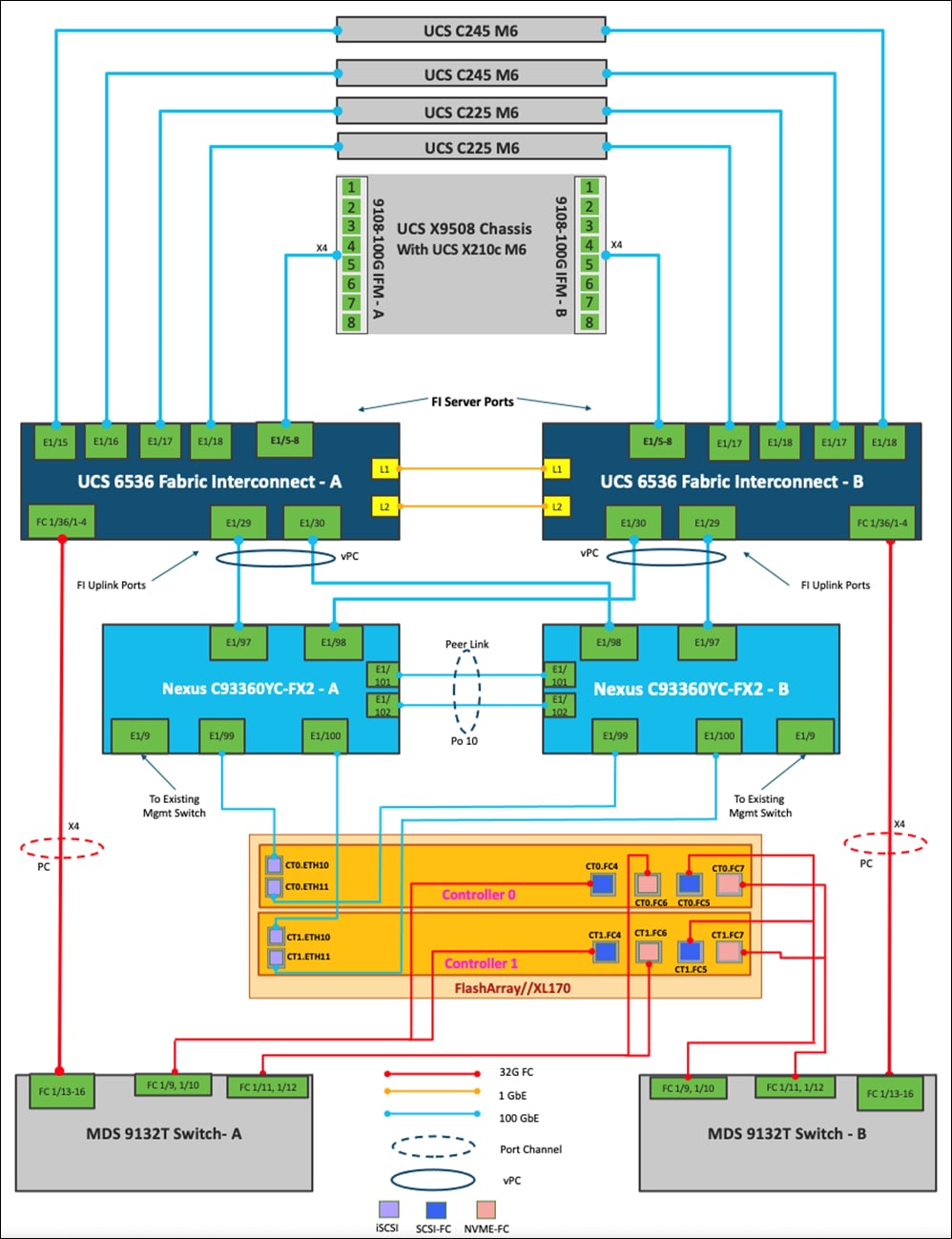
Table 5. Cisco Nexus C93360YC-FX2 - A Cabling Information
| Local Device |
Local Port |
Connection |
Remote Device |
Remote port |
| Cisco Nexus C93360YC-FX2 - A |
Eth 1/97 |
100Gbe |
Cisco UCS 6536-A |
Eth 1/29 |
|
|
Eth 1/98 |
100Gbe |
Cisco UCS 6536-B |
Eth 1/30 |
|
|
Eth 1/47 |
100Gbe |
Cisco Nexus 93180YC-Core |
Eth 1/41 |
|
|
Eth 1/48 |
100Gbe |
Cisco Nexus 93180YC-Core |
Eth 1/41 |
|
|
Eth 1/9 |
100Gbe |
Upstream Network Switch |
Any |
|
|
Mgmt0 |
1Gbe |
Gbe Management Switch |
Any |
|
|
Eth 1/99 * |
100Gbe |
FlashArray//XL170 Controller 0 |
CT0.ETH10 |
|
|
Eth 1/100 * |
100Gbe |
FlashArray//XL170 Controller 1 |
CT1.ETH10 |
|
|
Eth 1/101 |
100Gbe |
Nexus C93360YC-FX2 - B |
Eth 1/101 |
|
|
Eth 1/102 |
100Gbe |
Nexus C93360YC-FX2 - B |
Eth 1/102 |
Table 6. Cisco Nexus C93360YC-FX2 – B Cabling Information
| Local Device |
Local Port |
Connection |
Remote Device |
Remote port |
| Cisco Nexus C93360YC-FX2 - B |
Eth 1/97 |
100Gbe |
Cisco UCS 6536-A |
Eth 1/30 |
|
|
Eth 1/98 |
100Gbe |
Cisco UCS 6536-B |
Eth 1/29 |
|
|
Eth 1/47 |
100Gbe |
Cisco Nexus 93180YC-Core |
Eth 1/42 |
|
|
Eth 1/48 |
100Gbe |
Cisco Nexus 93180YC-Core |
Eth 1/42 |
|
|
Eth 1/9 |
10Gbe or 25Gbe |
Upstream Network Switch |
Any |
|
|
Mgmt0 |
1Gbe |
Gbe Management Switch |
Any |
|
|
Eth 1/99 * |
100Gbe |
FlashArray//XL170 Controller 0 |
CT0.ETH11 |
|
|
Eth 1/100 * |
100Gbe |
FlashArray//XL170 Controller 1 |
CT1.ETH11 |
|
|
Eth 1/101 |
100Gbe |
Nexus C93360YC-FX2 - A |
Eth 1/101 |
|
|
Eth 1/102 |
100Gbe |
Nexus C93360YC-FX2 - A |
Eth 1/102 |
Note: * iSCSI connectivity is not required if iSCSI storage access is not being implemented.
Table 7. Cisco UCS-6536-A Cabling Information
| Local Device |
Local Port |
Connection |
Remote Device |
Remote port |
| Cisco UCS-6536-A |
Eth 1/29 |
100Gbe |
Cisco Nexus C93360YC-FX2 - A |
Eth 1/97 |
|
|
Eth 1/30 |
100Gbe |
Cisco Nexus C93360YC-FX2 - B |
Eth 1/98 |
|
|
Eth 1/5 |
100Gbe |
Cisco UCS Chassis X9508 IFM 9108-100G A |
IFM 1/1 |
|
|
Eth 1/6 |
100Gbe |
Cisco UCS Chassis X9508 IFM 9108-100G A |
IFM 1/2 |
|
|
Eth 1/7 |
100Gbe |
Cisco UCS Chassis X9508 IFM 9108-100G A |
IFM 1/3 |
|
|
Eth 1/8 |
100Gbe |
Cisco UCS Chassis X9508 IFM 9108-100G A |
IFM 1/4 |
|
|
Eth 1/15 |
100Gbe |
Cisco UCS C245 M6 |
Port-1 |
|
|
Eth 1/16 |
100Gbe |
Cisco UCS C245 M6 |
Port-1 |
|
|
Eth 1/17 |
100Gbe |
Cisco UCS C225 M6 |
Port-1 |
|
|
Eth 1/18 |
100Gbe |
Cisco UCS C225 M6 |
Port-1 |
|
|
FC1/36/1 |
32G FC |
Cisco MDS 9132T-A |
FC1/13 |
|
|
FC1/36/2 |
32G FC |
Cisco MDS 9132T-A |
FC1/14 |
|
|
FC1/36/3 |
32G FC |
Cisco MDS 9132T-A |
FC1/15 |
|
|
FC1/36/4 |
32G FC |
Cisco MDS 9132T-A |
FC1/16 |
|
|
Mgmt0 |
1Gbe |
Gbe Management Switch |
Any |
Table 8. Cisco UCS-6536-B Cabling Information
| Local Device |
Local Port |
Connection |
Remote Device |
Remote port |
| Cisco UCS-6536-B |
Eth 1/29 |
100Gbe |
Cisco Nexus C93360YC-FX2 - B |
Eth 1/97 |
|
|
Eth 1/30 |
100Gbe |
Cisco Nexus C93360YC-FX2 - A |
Eth 1/98 |
|
|
Eth 1/5 |
100Gbe |
Cisco UCS Chassis X9508 IFM 9108-100G B |
IFM 1/1 |
|
|
Eth 1/6 |
100Gbe |
Cisco UCS Chassis X9508 IFM 9108-100G B |
IFM 1/2 |
|
|
Eth 1/7 |
100Gbe |
Cisco UCS Chassis X9508 IFM 9108-100G B |
IFM 1/3 |
|
|
Eth 1/8 |
100Gbe |
Cisco UCS Chassis X9508 IFM 9108-100G B |
IFM 1/4 |
|
|
Eth 1/15 |
100Gbe |
Cisco UCS C245 M6 |
Port-2 |
|
|
Eth 1/16 |
100Gbe |
Cisco UCS C245 M6 |
Port-2 |
|
|
Eth 1/17 |
100Gbe |
Cisco UCS C225 M6 |
Port-2 |
|
|
Eth 1/18 |
100Gbe |
Cisco UCS C225 M6 |
Port-2 |
|
|
FC1/36/1 |
32G FC |
Cisco MDS 9132T-B |
FC1/13 |
|
|
FC1/36/2 |
32G FC |
Cisco MDS 9132T-B |
FC1/14 |
|
|
FC1/36/3 |
32G FC |
Cisco MDS 9132T-B |
FC1/15 |
|
|
FC1/36/4 |
32G FC |
Cisco MDS 9132T-B |
FC1/16 |
|
|
Mgmt0 |
1Gbe |
Gbe Management Switch |
Any |
Table 9. Cisco MDS-9132T-A Cabling Information
| Local Device |
Local Port |
Connection |
Remote Device |
Remote port |
| Cisco MDS-9132T-A |
FC1/13 |
32Gb FC |
Cisco UCS-6536-A |
FC1/36/1 |
|
|
FC1/14 |
32Gb FC |
Cisco UCS-6536-A |
FC1/36/2 |
|
|
FC 1/15 |
32Gb FC |
Cisco UCS-6536-A |
FC1/36/3 |
|
|
FC 1/16 |
32Gb FC |
Cisco UCS-6536-A |
FC1/36/4 |
|
|
FC1/9 |
32Gb FC |
FlashArray//XL170 Controller 0 |
CT0.FC4 (scsi-fc) |
|
|
FC1/10 |
32Gb FC |
FlashArray//XL170 Controller 1 |
CT1.FC4 (scsi-fc) |
|
|
FC1/11 |
32Gb FC |
FlashArray//XL170 Controller 0 |
CT0.FC6 (nvme-fc) |
|
|
FC1/12 |
32Gb FC |
FlashArray//XL170 Controller 1 |
CT1.FC6 (nvme-fc) |
|
|
Mgmt0 |
1Gbe |
Gbe Management Switch |
Any |
Table 10.Cisco MDS-9132T-B Cabling Information
| Local Device |
Local Port |
Connection |
Remote Device |
Remote port |
| Cisco MDS-9132T-B |
FC1/13 |
32Gb FC |
Cisco UCS-6536-B |
FC1/36/1 |
|
|
FC1/14 |
32Gb FC |
Cisco UCS-6536-B |
FC1/36/2 |
|
|
FC 1/15 |
32Gb FC |
Cisco UCS-6536-B |
FC1/36/3 |
|
|
FC 1/16 |
32Gb FC |
Cisco UCS-6536-B |
FC1/36/4 |
|
|
FC1/9 |
32Gb FC |
FlashArray//XL170 Controller 0 |
CT0.FC5 (scsi-fc) |
|
|
FC1/10 |
32Gb FC |
FlashArray//XL170 Controller 1 |
CT1.FC5 (scsi-fc) |
|
|
FC1/11 |
32Gb FC |
FlashArray//XL170 Controller 0 |
CT0.FC7 (nvme-fc) |
|
|
FC1/12 |
32Gb FC |
FlashArray//XL170 Controller 1 |
CT1.FC7 (nvme-fc) |
|
|
Mgmt0 |
1Gbe |
Gbe Management Switch |
Any |
Table 11.Pure Storage FlashArray//XL170 Controller 0 Cabling Information
| Local Device |
Local Port |
Connection |
Remote Device |
Remote port |
| FlashArray//XL170 Controller 0 |
CT0.FC4 (scsi-fc) |
32Gb FC |
Cisco MDS 9132T-A |
FC 1/9 |
|
|
CT0.FC5 (scsi-fc) |
32Gb FC |
Cisco MDS 9132T-B |
FC 1/9 |
|
|
CT0.FC6 (nvme-fc) |
32Gb FC |
Cisco MDS 9132T-A |
FC 1/11 |
|
|
CT0.FC7 (nvme-fc) |
32Gb FC |
Cisco MDS 9132T-B |
FC 1/11 |
|
|
CT0.ETH10 * |
100Gbe |
Cisco Nexus C93360YC-FX2 - A |
Eth 1/99 |
|
|
CT0.ETH11 * |
100Gbe |
Cisco Nexus C93360YC-FX2 - B |
Eth 1/99 |
Note: * Required only if iSCSI storage access is implemented.
Note: This design uses SCSI-FCP for boot and datastore storage access and Port numbers 4 and 5 on each Pure FlashArray Controller have been used for the fibre channel connectivity, the ports 6 and 7 are used for FC-NVMe datastore access. All the four ports can be used for SCSI-FCP or FC-NVMe as needed but each port can only function as an SCSI-FCP or FC-NVMe port.
Table 12.Pure Storage FlashArray//X50 R3 Controller 1 Cabling Information
| Local Device |
Local Port |
Connection |
Remote Device |
Remote port |
| FlashArray//XL170 Controller 1 |
CT1.FC4 (scsi-fc) |
32Gb FC |
Cisco MDS 9132T-A |
FC 1/10 |
|
|
CT1.FC5 (scsi-fc) |
32Gb FC |
Cisco MDS 9132T-B |
FC 1/10 |
|
|
CT1.FC6 (nvme-fc) |
32Gb FC |
Cisco MDS 9132T-A |
FC 1/12 |
|
|
CT1.FC7 (nvme-fc) |
32Gb FC |
Cisco MDS 9132T-B |
FC 1/12 |
|
|
CT1.ETH10 * |
100Gbe |
Cisco Nexus C93360YC-FX2 - A |
Eth 1/100 |
|
|
CT1.ETH11 * |
100Gbe |
Cisco Nexus C93360YC-FX2 - B |
Eth 1/100 |
Note: * Required only if iSCSI storage access is implemented.
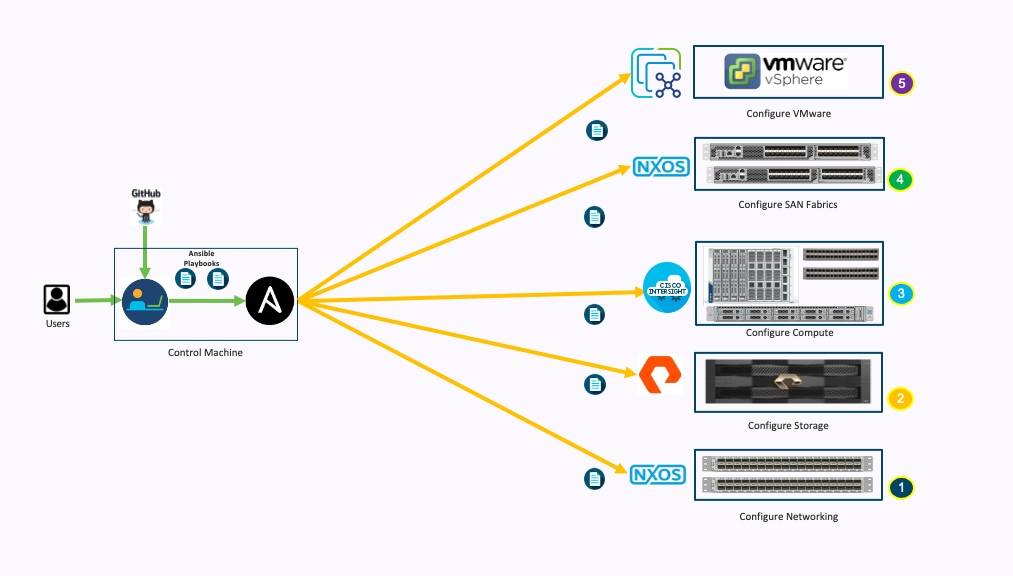
This section describes the automated solution deployment. Manual configuration of Network, Storage and Compute are detailed in subsequent section.
Ansible Automation Workflow
A repository is created in GitHub which Ansible playbooks to configure all the components of FlashStack including:
● Cisco UCS in Intersight Managed Mode
● Cisco Nexus Switches
● Cisco MDS Switches
● Pure FlashArray
● VMware ESXi
● VMware vCenter
Figure 4 illustrates the FlashStack with X-Series modular platform and Cisco UCS 5th Generation Fabric Technology solution implementation workflow, which is explained in the following sections.
Setting up the solution begins with a management workstation that has access to the internet and has a working installation of Ansible. The management workstation runs a variant of Linux or MacOS for ease of use with these command-line-based tools. Instructions for installing the workstation are not included in this document, but the basic installation and configuration of Ansible is explained. The following is a list of prerequisites:
● Getting Started with Red Hat Ansible
● To use the Ansible playbooks demonstrated in this document, the management workstation must also have a working installation of Git and access to the GitHub repository. The Ansible playbooks used in this document are cloned from the public repositories, located at: https://github.com/ucs-compute-solutions/FlashStack_IMM_Ansible
● The Cisco Nexus Switches, Pure Storage and Cisco UCS must be physically racked, cabled, powered, and configured with the management IP addresses before the Ansible-based installation procedure can begin.
● Before running each Ansible Playbook to setup the Network, Storage and Cisco Intersight, various variables must be updated based on the customers environment and specific implementation with values such as the VLANs, pools & ports on UCS, IP addresses for iSCSI interfaces and values needed for the OCP installation.
Prepare Management Workstation (Control Machine)
In this section, the installation steps are performed on the CentOS management host to prepare the host for solution deployment to support the automation of Cisco Intersight, Cisco Nexus, Pure Storage and VMWare installation using Ansible Playbooks.
Procedure 1. Prepare the Management Workstation
Step 1. Install the EPEL repository on the management host.
[root@FS-Automation ~]# yum install epel-release
Step 2. Install pip the package installer for Python.
[root@FS-Automation ~]# yum install python-pip
Step 3. Install Ansible engine.
[root@FS-Automation ~]# pip3 install ansible
Step 4. Verify the Ansible version to make sure it’s at least release 2.9.
[root@FS-Automation ~]# ansible –version
[root@FS-Automation bin]# ansible --version
ansible [core 2.13.4]
config file = /etc/ansible/ansible.cfg
configured module search path = ['/root/.ansible/plugins/modules', '/usr/share/ansible/plugins/modules']
ansible python module location = /usr/local/lib/python3.8/site-packages/ansible
ansible collection location = /root/.ansible/collections:/usr/share/ansible/collections
executable location = /usr/local/bin/ansible
python version = 3.8.12 (default, Sep 15 2022, 12:16:09) [GCC 4.8.5 20150623 (Red Hat 4.8.5-44)]
jinja version = 3.1.2
libyaml = True
Step 5. Install the paramiko package for Cisco Nexus automation.
[root@FS-Automation ~]# pip3 install paramiko
Step 6. SSH into each of the Nexus switches using Ansible so that the SSH keys are cached.
Step 7. Install the Pure Storage SDK.
[root@FS-Automation ~]# pip3 install purestorage
Step 8. Install ansible-galaxy collections for Cisco Intersight, Cisco Nexus, Pure Storage Array and VMWare as follows:
[root@FS-Automation ~]# ansible-galaxy collection install cisco.nxos
[root@FS-Automation ~]# ansible-galaxy collection install cisco.intersight
[root@FS-Automation ~]# ansible-galaxy collection install purestorage.flasharray
[root@FS-Automation ~]# ansible-galaxy collection install community.vmware
Procedure 2. Clone GitHub Collection
Clone the GitHub collection named FlashStack_IMM_Ansible ( https://github.com/ucs-compute-solutions/FlashStack_IMM_Ansible ) on the management workstation. Cloning the collections creates a local copy, which is then used to run the playbooks that have been created for this solution.
Step 1. Open a command-line or console interface on the management workstation and clone the GitHub collection using the following command:
https://github.com/ucs-compute-solutions/FlashStack_IMM_Ansible.git
Step 2. Change directories to the folder named Flashstack_IMM_Ansible
FlashStack Deployment using Playbooks
This sections explains the installation and configuration of all the infrastructure layers with in FlashStack. The Ansible Playbook tree structure is shown below with the directory structure and various roles and tasks:
.
├── create_pools.yml
├── create_server_policies.yml
├── create_server_profile_template.yml
├── group_vars
│ ├── all.yml
│ ├── mds.yml
│ └── nexus.yml
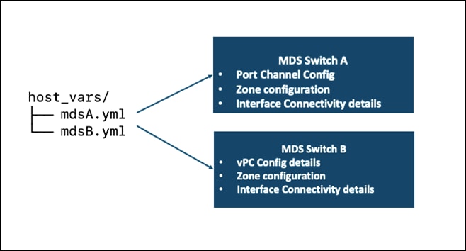
├── host_vars
│ ├── mdsA.yml
│ ├── mdsB.yml
│ ├── n9kA.yml
│ └── n9kB.yml
├── inventory
├── LICENSE
├── README.md
├── roles
│ ├── create_pools
│ │ ├── defaults
│ │ │ └── main.yml
│ │ └── tasks
│ │ ├── create_fc_ww_pools.yml
│ │ ├── create_ip_pools.yml
│ │ ├── create_iqn_pools.yml
│ │ ├── create_iscsi_pools.yml
│ │ ├── create_mac_pools.yml
│ │ ├── create_uuid_pool.yml
│ │ └── main.yml
│ ├── create_server_policies
│ │ ├── defaults
│ │ │ └── main.yml
│ │ └── tasks
│ │ ├── create_bios_policies.yml
│ │ ├── create_boot_order_policy.yml
│ │ ├── create_ethernet_adapter_policies.yml
│ │ ├── create_ethernet_network_control_policy.yml
│ │ ├── create_ethernet_network_group_policy.yml
│ │ ├── create_ethernet_qos_policy.yml
│ │ ├── create_fc_adapter_policy.yml
│ │ ├── create_fc_lan_connectivity_policy.yml
│ │ ├── create_fc_network_policy.yml
│ │ ├── create_fc_nvme_initiator_adapter_policy.yml
│ │ ├── create_fc_qos_policy.yml
│ │ ├── create_imc_policy.yml
│ │ ├── create_ipmi_policy.yml
│ │ ├── create_iscsi_adapter_policy.yml
│ │ ├── create_iscsi_boot_policy.yml
│ │ ├── create_iscsi_lan_connectivity_policy.yml
│ │ ├── create_iscsi_target_policy.yml
│ │ ├── create_kvm_policy.yml
│ │ ├── create_local_user_policy.yml
│ │ ├── create_san_connectivity_policy.yml
│ │ ├── create_vmedia_policy.yml
│ │ ├── gather_policy_info.yml
│ │ ├── gather_pool_info.yml
│ │ └── main.yml
│ ├── create_server_profile_template
│ │ ├── defaults
│ │ │ └── main.yml
│ │ └── tasks
│ │ ├── create_fc_server_profile_template.yml
│ │ ├── create_iscsi_server_profile_template.yml
│ │ ├── gather_policy_info.yml
│ │ └── main.yml
│ ├── ESXIhosts
│ │ ├── defaults
│ │ │ └── main.yml
│ │ └── tasks
│ │ ├── add_esxi_ntp.yml
│ │ ├── add_esxi_vmotion_vmk.yml
│ │ ├── create_esxi_ib_mgmt_PG.yml
│ │ ├── main.yml
│ │ ├── modify_esxi_vswitch0.yml
│ │ ├── set_esxi_powermgmt_policy.yml
│ │ └── upgrade_ESXi_drivers.yml
│ ├── ESXIiscsi
│ │ ├── defaults
│ │ │ └── main.yml
│ │ └── tasks
│ │ ├── add_esxi_iscsi_targets.yml
│ │ ├── add_esxi_ntp.yml
│ │ ├── create_esxi_iscsiB_PG.yml
│ │ ├── create_esxi_iscsi_vmk.yml
│ │ ├── main.yml
│ │ ├── modify_esxi_iscsi_vswitch.yml
│ │ └── rescan_esxi_iscsi_HBA.yml
│ ├── ESXIpostvC
│ │ ├── defaults
│ │ │ └── main.yml
│ │ └── tasks
│ │ ├── add_esxi_hosts_to_dvs.yml
│ │ ├── add_esxi_hosts_to_VC.yml
│ │ ├── add_esxi_vmotion_vmk.yml
│ │ └── main.yml
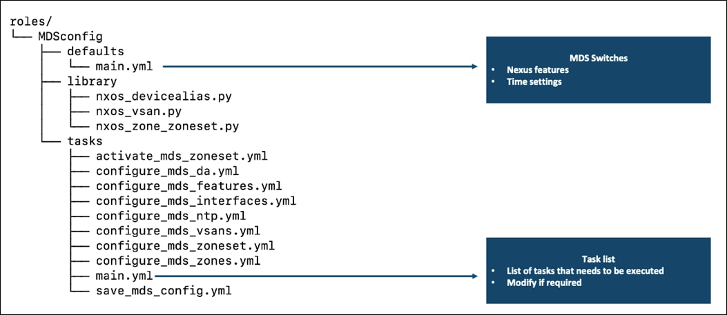
│ ├── MDSconfig
│ │ ├── defaults
│ │ │ └── main.yml
│ │ ├── library
│ │ │ ├── nxos_devicealias.py
│ │ │ ├── nxos_vsan.py
│ │ │ └── nxos_zone_zoneset.py
│ │ └── tasks
│ │ ├── activate_mds_zoneset.yml
│ │ ├── configure_mds_da.yml
│ │ ├── configure_mds_features.yml
│ │ ├── configure_mds_interfaces.yml
│ │ ├── configure_mds_ntp.yml
│ │ ├── configure_mds_vsans.yml
│ │ ├── configure_mds_zoneset.yml
│ │ ├── configure_mds_zones.yml
│ │ ├── main.yml
│ │ └── save_mds_config.yml
│ ├── NEXUSconfig
│ │ ├── defaults
│ │ │ └── main.yml
│ │ └── tasks
│ │ ├── configure_default_gw.yml
│ │ ├── configure_nxos_features.yml
│ │ ├── configure_nxos_global_settings.yml
│ │ ├── configure_nxos_ntp.yml
│ │ ├── configure_nxos_vlans.yml
│ │ ├── configure_nxos_vpc.yml
│ │ ├── initiate_nxos_config_backup.yml
│ │ ├── main.yml
│ │ ├── save_nxos_config.yml
│ │ └── set_nxos_interfaces.yml
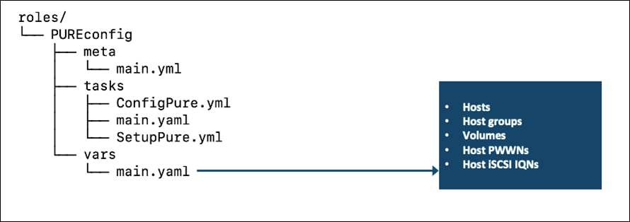
│ ├── PUREconfig
│ │ ├── meta
│ │ │ └── main.yml
│ │ ├── tasks
│ │ │ ├── ConfigPure.yml
│ │ │ ├── main.yaml
│ │ │ └── SetupPure.yml
│ │ └── vars
│ │ ├── main.yaml
│ │ └── main.yaml.true
│ └── VMWAREvcenter
│ ├── defaults
│ │ └── main.yml
│ └── tasks
│ ├── create_cluster.yml
│ ├── create_dc.yml
│ ├── create_vds_pg.yml
│ ├── create_vds.yml
│ └── main.yml
├── Setup_ESXi.yml
├── Setup_MDS.yml
├── Setup_Nexus.yml
├── Setup_Pure.yml
├── Setup_vCenter.yml
└── update_all_inventory.yml
Note: The following information must be modified based on your environment and more information needs to be modified specific to each device automation. This is explained later in the document.
● inventory - contains the variables such as device IP addresses and authentication details.
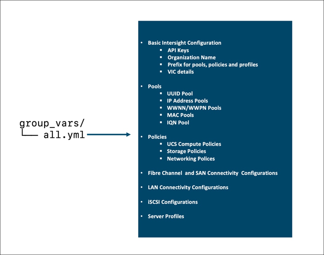
● group_vars/all.yml – contains the required input for Intersight, Nexus and MDS configuration, VLAN ids required, ESXi configuration etc. for the solution deployment. Update this file based on your environment.
Cisco Intersight Configuration
The Cisco Intersight playbooks in this repository perform the following functions:
● Create various pools required to setup a Server Profile Template
● Create various policies required to setup a Server Profile Template
● Create iSCSI and/or FC Server Profile Templates
After successfully executing the playbooks, one or many server profiles can be easily derived and attached to the compute node from Cisco Intersight dashboard.
Cisco Intersight Access Requirement
To execute the playbooks against your Cisco Intersight account, you need to complete the following additional steps of creating an API key and saving the Secrets_File: https://community.cisco.com/t5/data-center-and-cloud-documents/intersight-api-overview/ta-p/3651994
The API key and Secrets_Filename information is added to the group_vars/all.yml. The default Secrets_File value in all.yml assumes Secrets_File was copied to the same folder/directory where Ansible Playbooks were cloned (alongside inventory file).
Note: The addition of UCS to Intersight Account or configuration of Domain Profile to setup UCS is not part of this repository and will have to be performed manually before executing the playbooks.
Note: The playbooks do not create an organization and assume an organization (default or otherwise) has already been setup under Intersight account. The organization name must be updated in group_vars/all.yml(org_name) for successful execution of the playbooks.
Procedure 3. Setting up Variables
Step 1. Most of the required configuration parameters required to create pools, policies and server profiles templates are present in FlashStack_IMM_Ansible/group_vars/all.yml. Edit the following variable files to ensure proper Intersight variables are entered:
● FlashStack_IMM_Ansible/group_vars/all.yml
● FlashStack_IMM_Ansible/roles/ create_pools/defaults/main.yml
● FlashStack_IMM_Ansible/roles/create_server_policies/defaults
● FlashStack_IMM_Ansible/roles/create_server_profile_template/defaults
Step 2. Edit the FlashStack_IMM_Ansible/group_vars/all.yml file
FlashStack Network Configuration
Before the Ansible Nexus switch setup playbook can be run, the Nexus switches must be brought up with a management IP address. The following procedures describe the basic configuration of the Cisco Nexus switches for use in a base FlashStack environment. This procedure assumes the use of Cisco Nexus C93360YC-FX2 running NXOS version 10.2(3), the Cisco suggested Nexus switch release at the time of this validation.
Note: Make sure the FlashStack cabling and initial configuration has been completed on the Cisco Nexus switches. The Cisco Nexus automation includes the VPC connectivity between the Cisco UCS FI’s and the Cisco Nexus C93360YC-FX2 switches using 100G ports.
Procedure 1. Modification Prerequisites
The following information must be modified based on your specific environment, before running the Cisco Nexus Automation Playbook.
Step 1. Edit the following variable files to ensure proper Nexus variables are entered:
● FlashStack_IMM_Ansible/inventory
● FlashStack_IMM_Ansible/group_vars/all.yml
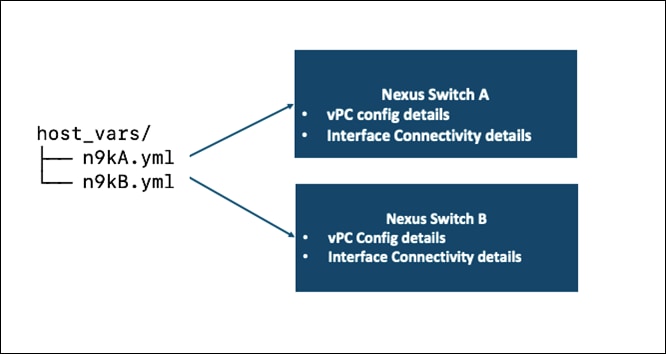
● FlashStack_IMM_Ansible/host_vars/n9kA.yml
● FlashStack_IMM_Ansible/host_vars/n9kB.yml
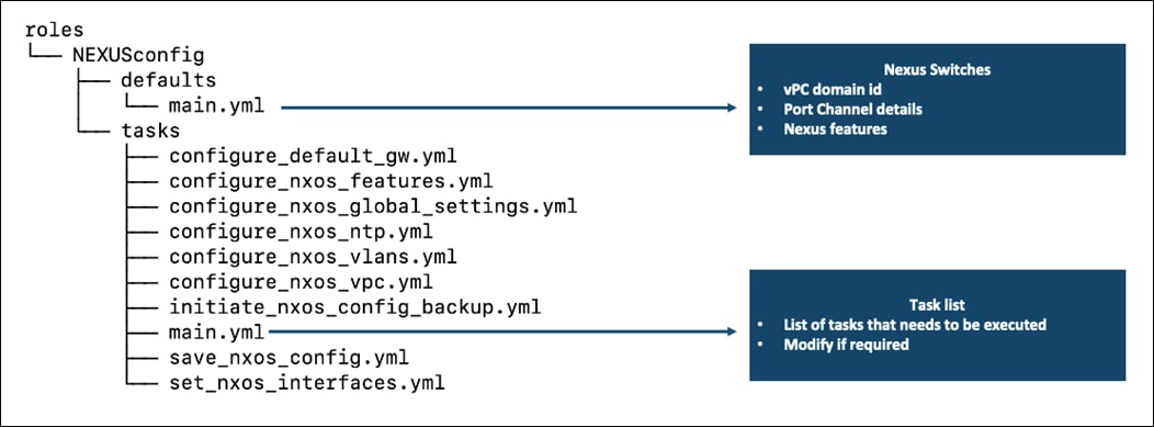
● FlashStack_IMM_Ansible/roles/NEXUSconfig/defaults/main.yml
Step 2. Edit the FlashStack_IMM_Ansible/group_vars/all.yml file
Step 3. vPC domain id, Port Channel details and Cisco Nexus features in the following files if using different port channel ids or features.
Step 4. When the information has been updated in the respective files, run the Cisco Nexus switch Ansible playbook:
[root@FS-Automation FlashStack_IMM_Ansible]# ansible-playbook -i inventory Setup_Nexus.yml
Step 5. Login into the Cisco Nexus switches and verify the configuration has been completed as desired before proceeding with the next section to configure Pure Storage.
FlashStack Initial Storage Configuration
Procedure 1. Configure Initial FlashStack Storage
Note: Skip this section if the initial configuration of FlashArray is performed by a Pure Implementation engineer.
Step 1. To configure the FlashStack storage, follow these steps:
Step 2. Update the following information as required based on your environment before running the MDS and UCS Automation Playbook.
Step 3. There are three variables defined in the group_vars/all.yml file as follows, comment out the lines based on what configuration is required:
initial_fa_config: "yes" – required to perform the initial configuration of FlashArray
configure_iscsi: “yes” – required to configure the iSCSI ports on the FlashArray
configure_fc: “yes” – comment this line during initial configuration of FlashArray, it needs to be enabled or disabled when configuring the storage on FlashArray at a later point in time.
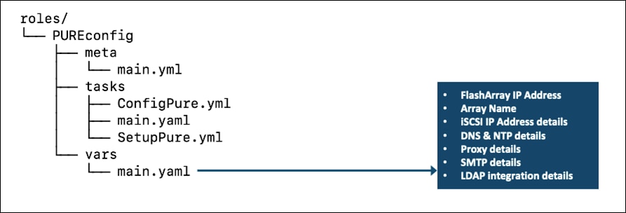
Step 4. Change directory to “FlashStack_IMM_Ansible/roles/PUREconfig/vars” on your management host.
Step 5. Following details need to be updated in the main.yaml file:
Note: Change the values in the above mentioned files with caution, only change the information that is required. All the other files can be left to defaults, modify them only if you want to go with a different naming convention or if you do not have the identical hardware discussed in this design.
Step 6. When the information has been updated in the respective files, run the Ansible playbook:
[root@FS-Automation FlashStack_IMM_Ansible]# ansible-playbook -i inventory Setup_Pure.yml
FlashStack Cisco MDS Ansible Switch Configuration
Ansible playbooks for MDS can be leveraged if the environment is configured for Fibre Channel storage. Before the Ansible MDS switch setup playbook can be run, the MDS switches must be brought up with a management IP address. The following procedures describe the basic configuration of the Cisco MDS switches for use in a base FlashStack environment. This procedure assumes the use of Cisco MDS 9132T switches running software version 8.4(2c), the Cisco suggested MDS switch release at the time of this validation.
Procedure 1. Configure the FlashStack Cisco MDS Ansible Switch
The following information must be modified based on your specific environment, before running the Cisco MDS Automation Playbook.
Step 1. Edit the following variable files to ensure proper MDS variables are entered:
● FlashStack_IMM_Ansible/inventory
● FlashStack_IMM_Ansible/group_vars/all.yml
● FlashStack_IMM_Ansible/host_vars/mdsA.yml
● FlashStack_IMM_Ansible/host_vars/mdsB.yml
● FlashStack_IMM_Ansible/roles/MDSconfig/defaults/main.yml
Step 2. Switch Interface details in the following files if using different ports.
Step 3. Cisco MDS features in the following files. Modify if using different features.
Step 4. When the information has been updated in the respective files, run the MDS switch Ansible playbook:
[root@FS-Automation FlashStack_IMM_Ansible]# ansible-playbook -i inventory Setup_MDS.yml
Step 5. Login into the MDS switches and verify the configuration has been completed as desired before proceeding with the next section.
FlashStack Storage Configuration
Procedure 1. Configure the FlashStack Storage
Note: Update the following information as required based on your environment.
Step 1. Change the directory to “FlashStack_IMM_Ansible/roles/PUREconfig/vars” on your management host.
Step 2. The following details need to be updated in the main.yaml file:
Step 3. There are three variables defined in the group_vars/all.yml file as follows, comment out the lines based on what configuration is required:
● configure_fc: “yes” – required to configure scsi-fc setup on the MDS.
● configure_fc-nvme: “yes” – uncomment this variable if nvme-fc configuration is also required.
Step 4. When the information has been updated in the respective files, run the Ansible playbook:
[root@FS-Automation FlashStack_IMM_Ansible]# ansible-playbook -i inventory Setup_Pure.yml
VMware vSphere 7.0 U2 Installation and Configuration
Procedure 1. Configure the VMware ESXi Hosts from the management workstation
Step 1. Edit the following variable files to ensure proper ESXi variables are entered:
● FlashStack_IMM_Ansible/inventory
● FlashStack_IMM_Ansible/group_vars/all.yml
● FlashStack_IMM_Ansible/roles/ESXIhosts/defaults/main.yml
● FlashStack_IMM_Ansible/roles/ESXIiscsi/defaults/main.yml (If using iSCSI boot)
Step 2. When the information has been updated in the respective files, run the Ansible playbook:
[root@FS-Automation FlashStack_IMM_Ansible]# ansible-playbook -i inventory Setup_ESXi.yml
Step 3. The remaining steps in the VMware vSphere Client are manual steps that should be completed whether an Ansible configuration or manual configuration is being done.
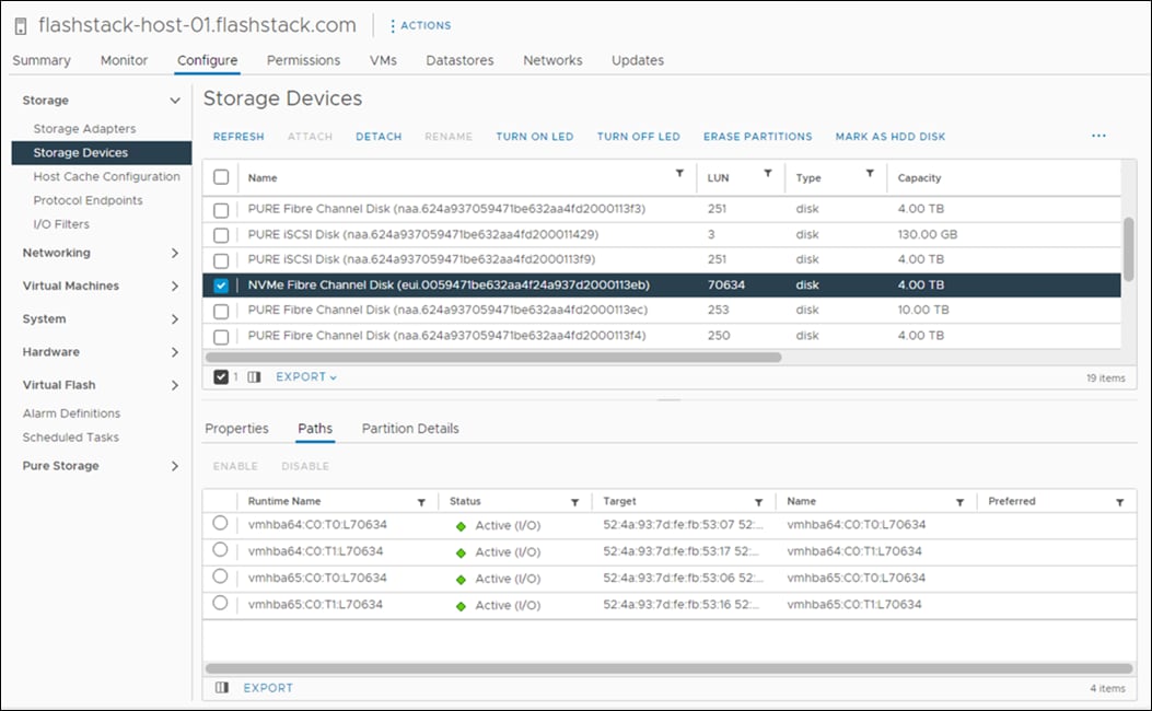
Step 4. Verify that the NVMe Fibre Channel Disk is mounted on each ESXi host. Under Hosts and Clusters select the ESXi host.
Step 5. In the center pane, select Configure > Storage > Storage Devices. The NVMe Fibre Channel Disk should be listed under Storage Devices.
Step 6. Select the NVMe Fibre Channel Disk, then select Paths underneath. Verify 4 paths have a status of Active (I/O).
Step 7. Repeat steps 1-3 for all 3 hosts.
Step 8. For any of the three hosts, right-click the host under Hosts and Clusters and select Storage > New Datastore. Leave VMFS selected and click NEXT.
Step 9. Name the datastore and select the NVMe Fibre Channel Disk. Click NEXT.
Step 10. Leave VMFS 6 selected and click NEXT.
Step 11. Leave all Partition configuration values at the default values and click NEXT.
Step 12. Review the information and click FINISH.
Step 13. Select Storage and select the just-created NVMe datastore. In the center pane, select Hosts. Ensure all three hosts have the datastore mounted.
ESXi Host Multipathing Configuration
Procedure 1. Configure the ESXi Host Multipathing
Step 1. From the vCenter management GUI.
Step 2. Go to Hosts and Clusters view.
Step 3. Select a Host.
Step 4. Click on the Configure tab.
Step 5. Select Storage Devices.
Step 6. Select an NVMe device.
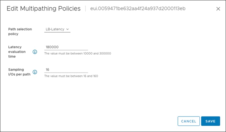
Step 7. Select Properties. Click on ACTIONS in Multipathing Policies.
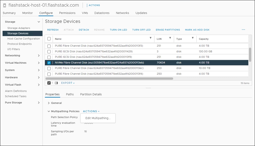
Step 8. Click Edit Multipathing.
vCenter and Final ESXi Ansible Setup
Procedure 1. Configure the VMware vCenter
This procedure can be used to complete the configuration of the VMware vCenter and the three management ESXi hosts.
Step 1. Edit the following variable files to ensure proper variables are entered:
● FlashStack_IMM_Ansible/inventory
● FlashStack_IMM_Ansible/group_vars/all.yml
● FlashStack_IMM_Ansible/roles/ESXIpostvC/defaults/main.yml
Step 2. Run the Setup_vCenter.yml Ansible playbook.
[root@FS-Automation FlashStack_IMM_Ansible]# ansible-playbook -i inventory Setup_vCenter.yml
The procedures in this chapter describe how to configure the Cisco Nexus switches for use in a base FlashStack environment. These procedures assumes the use of Cisco Nexus C93360YC-FX2 switches running NX-OS 10.2(3). Configuring on a differing model of Cisco Nexus 9000 series switches should be comparable but may differ slightly with model and changes in NX-OS release. The Cisco Nexus C93360YC-FX2 switch, and the NX-OS 10.2(3) release were used in validating this FlashStack solution, so the steps will reflect this model and release.
Physical cabling should be completed by following the diagram and table references in section FlashStack Cabling.
The following procedures describe how to configure the Cisco Nexus C93360YC-FX2 switches for use in a base FlashStack environment. This procedure assumes the use of Cisco Nexus 9000 10.2(3), the Cisco suggested Nexus switch release at the time of this validation.
Note: The procedure includes the setup of NTP distribution on both the mgmt0 port and the in-band management VLAN. The interface-vlan feature and ntp commands are used to set this up. This procedure also assumes that the default VRF is used to route the in-band management VLAN.
Procedure 1. Set up the Initial Configuration for Cisco Nexus A Switch
Cisco Nexus A
Step 1. Configure the switch.
Note: On initial boot and connection to the serial or console port of the switch, the NX-OS setup should automatically start and attempt to enter Power on Auto Provisioning.
Abort Power On Auto Provisioning [yes - continue with normal setup, skip - bypass password and basic configuration, no - continue with Power On Auto Provisioning] (yes/skip/no)[no]: yes
Disabling POAP.......Disabling POAP
poap: Rolling back, please wait... (This may take 5-15 minutes)
---- System Admin Account Setup ----
Do you want to enforce secure password standard (yes/no) [y]: Enter
Enter the password for "admin": <password>
Confirm the password for "admin": <password>
Would you like to enter the basic configuration dialog (yes/no): yes
Create another login account (yes/no) [n]: Enter
Configure read-only SNMP community string (yes/no) [n]: Enter
Configure read-write SNMP community string (yes/no) [n]: Enter
Enter the switch name: <nexus-A-hostname>
Continue with Out-of-band (mgmt0) management configuration? (yes/no) [y]: Enter
Mgmt0 IPv4 address: <nexus-A-mgmt0-ip>
Mgmt0 IPv4 netmask: <nexus-A-mgmt0-netmask>
Configure the default gateway? (yes/no) [y]: Enter
IPv4 address of the default gateway: <nexus-A-mgmt0-gw>
Configure advanced IP options? (yes/no) [n]: Enter
Enable the telnet service? (yes/no) [n]: Enter
Enable the ssh service? (yes/no) [y]: Enter
Type of ssh key you would like to generate (dsa/rsa) [rsa]: Enter
Number of rsa key bits <1024-2048> [1024]: Enter
Configure the ntp server? (yes/no) [n]: Enter
Configure default interface layer (L3/L2) [L2]: Enter
Configure default switchport interface state (shut/noshut) [noshut]: shut
Enter basic FC configurations (yes/no) [n]: n
Configure CoPP system profile (strict/moderate/lenient/dense) [strict]: Enter
Would you like to edit the configuration? (yes/no) [n]: Enter
Step 2. Review the configuration summary before enabling the configuration.
Use this configuration and save it? (yes/no) [y]: Enter
Procedure 2. Set up the Initial Configuration for Cisco Nexus B Switch
Cisco Nexus B
Step 1. Configure the switch.
Note: On initial boot and connection to the serial or console port of the switch, the NX-OS setup should automatically start and attempt to enter Power on Auto Provisioning.
Abort Power On Auto Provisioning [yes - continue with normal setup, skip - bypass password and basic configuration, no - continue with Power On Auto Provisioning] (yes/skip/no)[no]: yes
Disabling POAP.......Disabling POAP
poap: Rolling back, please wait... (This may take 5-15 minutes)
---- System Admin Account Setup ----
Do you want to enforce secure password standard (yes/no) [y]: Enter
Enter the password for "admin": <password>
Confirm the password for "admin": <password>
Would you like to enter the basic configuration dialog (yes/no): yes
Create another login account (yes/no) [n]: Enter
Configure read-only SNMP community string (yes/no) [n]: Enter
Configure read-write SNMP community string (yes/no) [n]: Enter
Enter the switch name: <nexus-B-hostname>
Continue with Out-of-band (mgmt0) management configuration? (yes/no) [y]: Enter
Mgmt0 IPv4 address: <nexus-B-mgmt0-ip>
Mgmt0 IPv4 netmask: <nexus-B-mgmt0-netmask>
Configure the default gateway? (yes/no) [y]: Enter
IPv4 address of the default gateway: <nexus-B-mgmt0-gw>
Configure advanced IP options? (yes/no) [n]: Enter
Enable the telnet service? (yes/no) [n]: Enter
Enable the ssh service? (yes/no) [y]: Enter
Type of ssh key you would like to generate (dsa/rsa) [rsa]: Enter
Number of rsa key bits <1024-2048> [1024]: Enter
Configure the ntp server? (yes/no) [n]: Enter
Configure default interface layer (L3/L2) [L2]: Enter
Configure default switchport interface state (shut/noshut) [noshut]: shut
Enter basic FC configurations (yes/no) [n]: Enter
Configure CoPP system profile (strict/moderate/lenient/dense) [strict]: Enter
Would you like to edit the configuration? (yes/no) [n]: Enter
Step 2. Review the configuration summary before enabling the configuration.
Use this configuration and save it? (yes/no) [y]: Enter
FlashStack Cisco Nexus Switch Configuration
Cisco Nexus A and Cisco Nexus B
Step 1. Log in as admin.
Step 2. Run the following commands:
config t
feature udld
feature interface-vlan
feature lacp
feature vpc
feature lldp
feature nxapi
Procedure 2. Set Global Configurations on both switches
Cisco Nexus A and Cisco Nexus B
Step 1. Run the following commands to set global configurations:
spanning-tree port type network default
spanning-tree port type edge bpduguard default
spanning-tree port type edge bpdufilter default
system default switchport
system default switchport shutdown
port-channel load-balance src-dst l4port
ntp server <global-ntp-server-ip> use-vrf management
ntp master 3
clock timezone <timezone> <hour-offset> <minute-offset>
clock summer-time <timezone> <start-week> <start-day> <start-month> <start-time> <end-week> <end-day> <end-month> <end-time> <offset-minutes>
ip route 0.0.0.0/0 <ib-mgmt-vlan-gateway>
copy run start
Note: It is important to configure the local time so that logging time alignment and any backup schedules are correct. For more information on configuring the timezone and daylight savings time or summer time, please see https://www.cisco.com/c/en/us/td/docs/dcn/nx-os/nexus9000/102x/configuration/fundamentals/cisco-nexus-9000-nx-os-fundamentals-configuration-guide-102x/m-basic-device-management.html#task_1231769
Sample clock commands for the United States Eastern timezone are:
clock timezone EST -5 0
clock summer-time EDT 2 Sunday March 02:00 1 Sunday November 02:00 60
Procedure 3. Create VLANs on both switches
Cisco Nexus A and Cisco Nexus B
Step 1. From the global configuration mode, run the following commands:
vlan <oob-mgmt-vlan-id>
name OOB-MGMT
vlan <ib-mgmt-vlan-id>
name IB-MGMT-VLAN
vlan <native-vlan-id>
name Native-Vlan
vlan <vmotion-vlan-id>
name vMotion-VLAN
vlan <vm-traffic-vlan-id>
name VM-Traffic-VLAN
exit
Procedure 4. Add NTP Distribution Interface
Cisco Nexus A
Step 1. From the global configuration mode, run the following commands:
interface Vlan<ib-mgmt-vlan-id>
ip address <switch-a-ntp-ip>/<ib-mgmt-vlan-netmask-length>
no shutdown
exit
ntp peer <switch-b-ntp-ip> use-vrf default
Cisco Nexus B
Step 2. From the global configuration mode, run the following commands:
interface Vlan<ib-mgmt-vlan-id>
ip address <switch-b-ntp-ip>/<ib-mgmt-vlan-netmask-length>
no shutdown
exit
ntp peer <switch-a-ntp-ip> use-vrf default
Procedure 5. Add Individual Port Descriptions for Troubleshooting and Enable UDLD for Cisco UCS Interfaces
Cisco Nexus A
Note: In this step and in the following sections, configure the Cisco UCS 6536 fabric interconnect clustername <ucs-clustername> interfaces as appropriate to your deployment.
Step 1. From the global configuration mode, run the following commands:
interface Eth1/97
description <ucs-clustername>-A:1/29
udld enable
interface Eth1/98
description <ucs-clustername>-B:1/30
udld enable
Note: For fibre optic connections to Cisco UCS systems (AOC or SFP-based), entering udld enable will result in a message stating that this command is not applicable to fiber ports. This message is expected. If you have fibre optic connections, do not enter the udld enable command.
interface Ethernet1/101
description Peer Link <<nexus-B-hostname>>:Eth1/101
interface Ethernet1/102
description Peer Link <<nexus-B-hostname>>:Eth1/102
Procedure 6. Add Individual Port Descriptions for Troubleshooting and Enable Aggressive UDLD on copper interfaces for Cisco UCS
Cisco Nexus B
Step 1. From the global configuration mode, run the following commands:
interface Eth1/97
description <ucs-clustername>-B:1/29
udld enable
interface Eth1/98
description <ucs-clustername>-A:1/30
udld enable
Note: For fibre optic connections to Cisco UCS systems (AOC or SFP-based), entering udld enable will result in a message stating that this command is not applicable to fiber ports. This message is expected.
interface Ethernet1/101
description Peer Link <<nexus-A-hostname>>:Eth1/101
interface Ethernet1/102
description Peer Link <<nexus-A-hostname>>:Eth1/102
Procedure 7. Create Port Channels
Cisco Nexus A and Cisco Nexus B
Step 1. From the global configuration mode, run the following commands:
interface Po10
description vPC peer-link
interface Eth1/101-102
channel-group 10 mode active
no shutdown
interface Po11
description <ucs-clustername>-A
interface Eth1/97
channel-group 11 mode active
no shutdown
interface Po12
description <ucs-clustername>-B
interface Eth1/98
channel-group 12 mode active
no shutdown
exit
copy run start
Procedure 8. Configure Port Channel Parameters
Cisco Nexus A and Cisco Nexus B
Step 1. From the global configuration mode, run the following commands:
interface Po10
switchport mode trunk
switchport trunk native vlan <native-vlan-id>
switchport trunk allowed vlan <ib-mgmt-vlan-id>, <vmotion-vlan-id>, <vm-traffic-vlan-id>, <oob-mgmt-vlan-id>
spanning-tree port type network
speed 100000
duplex full
state enabled
interface Po11
switchport mode trunk
switchport trunk native vlan <native-vlan-id>
switchport trunk allowed vlan <ib-mgmt-vlan-id>, <vmotion-vlan-id>, <vm-traffic-vlan-id>, <oob-mgmt-vlan-id>
spanning-tree port type edge trunk
mtu 9216
state enabled
interface Po12
switchport mode trunk
switchport trunk native vlan <native-vlan-id>
switchport trunk allowed vlan <ib-mgmt-vlan-id>, <vmotion-vlan-id>, <vm-traffic-vlan-id>, <oob-mgmt-vlan-id>
spanning-tree port type edge trunk
mtu 9216
state enabled
exit
copy run start
Procedure 9. Configure Virtual Port Channels
Cisco Nexus A
Step 1. From the global configuration mode, run the following commands:
vpc domain <nexus-vpc-domain-id>
role priority 10
peer-keepalive destination <nexus-B-mgmt0-ip> source <nexus-A-mgmt0-ip>
peer-switch
peer-gateway
auto-recovery
delay restore 150
ip arp synchronize
interface Po10
vpc peer-link
interface Po11
vpc 11
interface Po12
vpc 12
exit
copy run start
Procedure 10. Configure Virtual Port Channels
Cisco Nexus B
Step 1. From the global configuration mode, run the following commands:
vpc domain <nexus-vpc-domain-id>
role priority 20
peer-keepalive destination <nexus-A-mgmt0-ip> source <nexus-B-mgmt0-ip>
peer-switch
peer-gateway
auto-recovery
delay restore 150
ip arp synchronize
interface Po10
vpc peer-link
interface Po11
vpc 11
interface Po12
vpc 12
exit
copy run start
Uplink into Existing Network Infrastructure
Depending on the available network infrastructure, several methods and features can be used to uplink the FlashStack environment. If an existing Cisco Nexus environment is present, we recommend using vPCs to uplink the Cisco Nexus switches included in the FlashStack environment into the infrastructure. The previously described procedures can be used to create an uplink vPC to the existing environment. Make sure to run copy run start to save the configuration on each switch after the configuration is completed.
The following commands can be used to check for correct switch configuration:
Note: Some of these commands need to run after further configuration of the FlashStack components are complete to see complete results.
show run
show vpc
show port-channel summary
show ntp peer-status
show cdp neighbors
show lldp neighbors
show run int
show int
show udld neighbors
show int status
Cisco Nexus iSCSI Configuration
Procedure 1. Create Infrastructure iSCSI VLANs on Cisco Nexus A and Cisco Nexus B
Step 1. From the global configuration mode, run the following commands:
config t
vlan <infra-iscsi-a-vlan-id>
name Infra-iSCSI-A-VLAN
vlan <infra-iscsi-b-vlan-id>
name Infra-iSCSI-B-VLAN
exit
Procedure 2. Add iSCSI Individual Port Descriptions for Troubleshooting and Enable UDLD for Pure iSCSI Interfaces
Cisco Nexus A
Step 1. From the global configuration mode, run the following commands:
config t
interface Ethernet1/99
description <<var_flasharray_hostname>>-CT0.ETH10
interface Ethernet1/100
description <<var_flasharray_hostname>>-CT1.ETH10
Cisco Nexus B
Step 1. From the global configuration mode, run the following commands:
config t
interface Ethernet1/99
description <<var_flasharray_hostname>>-CT0.ETH11
interface Ethernet1/100
description <<var_flasharray_hostname>>-CT1.ETH11
Configure iSCSI interfaces for Cisco Nexus 93360YC-FX2-A
To configure iSCSI interfaces for this deployment, run the following commands on Cisco Nexus C93360YC-FX2 - A:
config t
interface Ethernet1/99
switchport
switchport access valn <<var-iscsi-a-vlan-id>>
mtu 9216
no negoriate auto
no shut
interface Ethernet1/100
switchport
switchport access valn <<var-iscsi-a-vlan-id>>
mtu 9216
no negoriate auto
no shut
Configure iSCSI interfaces for Cisco Nexus 93360YC-FX2-B
To configure iSCSI interfaces for this deployment, run the following commands on Cisco Nexus C93360YC-FX2 - B:
config t
interface Ethernet1/99
switchport
switchport access valn <<var-iscsi-b-vlan-id>>
mtu 9216
no negoriate auto
no shut
interface Ethernet1/100
switchport
switchport access valn <<var-iscsi-b-vlan-id>>
mtu 9216
no negoriate auto
no shut
Procedure 3. Add Infrastructure iSCSI VLANs to Port-Channels on Cisco Nexus A and Cisco Nexus B
Step 1. From the global configuration mode, run the following commands:
interface Po10
switchport trunk allowed vlan add <infra-iscsi-a-vlan-id>,<infra-iscsi-b-vlan-id>
exit
interface Po121
switchport trunk allowed vlan add <infra-iscsi-a-vlan-id>,<infra-iscsi-b-vlan-id>
exit
interface Po123
switchport trunk allowed vlan add <infra-iscsi-a-vlan-id>,<infra-iscsi-b-vlan-id>
exit
copy run start
Cisco UCS Intersight Managed Mode Configuration
The procedures in this chapter describe how to configure the Cisco UCS domain for use in a base FlashStack environment. These procedures assumes you’re using Cisco UCS Fabric Interconnects running in Intersight managed mode.
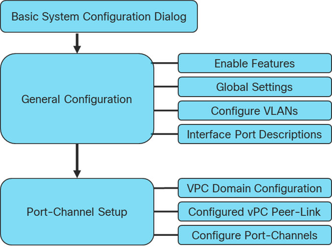
Cisco UCS Configuration Workflow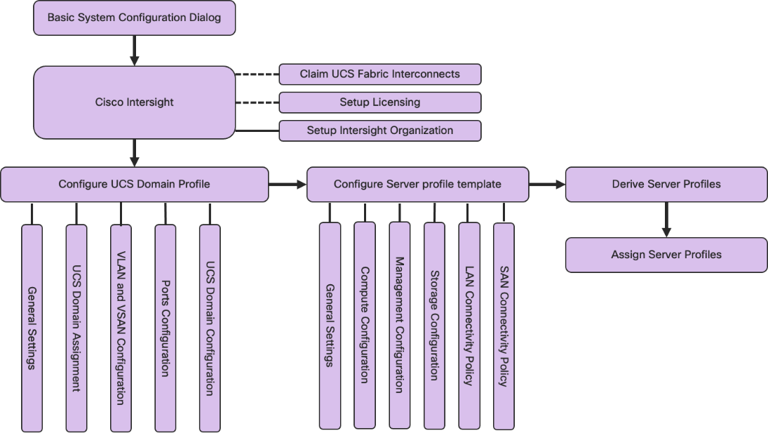
Physical cabling should be completed by following the diagram and table references in section FlashStack Cabling.
Cisco Intersight Managed Mode Configuration
The Cisco Intersight™ platform is a management solution delivered as a service with embedded analytics for Cisco® and third-party IT infrastructures. The Cisco Intersight managed mode (also referred to as Cisco IMM or Intersight managed mode) is a new architecture that manages Cisco Unified Computing System™ (Cisco UCS®) fabric interconnect–attached systems through a Redfish-based standard model. Cisco Intersight managed mode standardizes both policy and operation management for Cisco UCS X210c M6 compute nodes used in this deployment guide.
Set up Cisco Intersight Managed Mode on Cisco UCS Fabric Interconnects
The Cisco UCS fabric interconnects need to be set up to support Cisco Intersight managed mode. When converting an existing pair of Cisco UCS fabric interconnects from Cisco UCS Manager (UCSM) mode to Intersight Mange Mode (IMM), first erase the configuration and reboot your system.
Note: Converting fabric interconnects to Cisco Intersight managed mode is a disruptive process, and configuration information will be lost. Customers are encouraged to make a backup of their existing configuration. If a Cisco UCS software version that supports Intersight Managed Mode (4.1(3) or later) is already installed on Cisco UCS Fabric Interconnects, do not upgrade the software to a recommended recent release using Cisco UCS Manager. The software upgrade will be performed using Cisco Intersight to make sure Cisco UCS X-Series firmware is part of the software upgrade.
This section provides the detailed procedures for configuring the Cisco Unified Computing System (Cisco UCS) for use in a FlashStack environment. These steps are necessary to provision the Cisco UCS Compute nodes and should be followed precisely to avoid improper configuration.
Procedure 1. Cisco UCS Fabric Interconnect A
Configure the Cisco UCS for use in a FlashStack environment in Cisco Intersight managed mode.
Step 1. Connect to the console port on the first Cisco UCS Fabric Interconnect.
Step 2. Power on the Fabric Interconnect.
Step 3. Power-on self-test messages will be displayed as the Fabric Interconnect boots.
Step 4. When the unconfigured system boots, it prompts you for the setup method to be used. Enter console to continue the initial setup using the console CLI.
Step 5. Enter the “intersight” as the management mode for the Fabric Interconnect.
Step 6. Enter y to confirm that you want to continue the initial setup.
Step 7. To use a strong password, enter y.
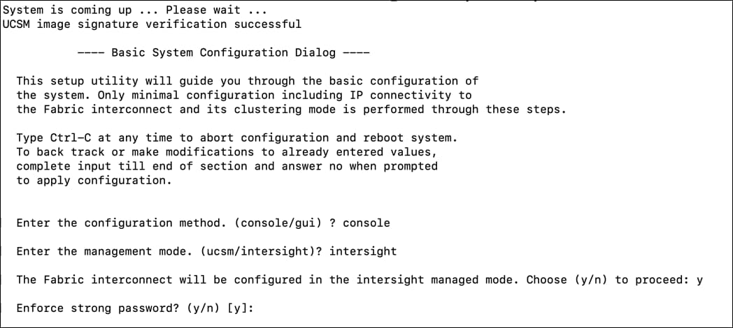
Step 8. Enter the password for the admin account.
Step 9. To confirm, re-enter the password for the admin account.
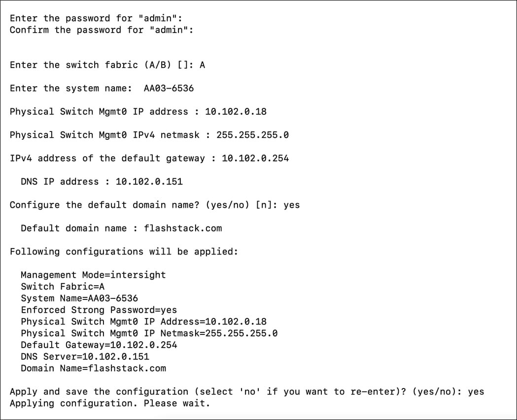
Step 10. Enter yes to continue the initial setup for a cluster configuration.
Step 11. Enter the Fabric Interconnect fabric (either A or B).
Step 12. Enter the system name.
Step 13. Enter the IPv4 or IPv6 address for the management port of the Fabric Interconnect.
Note: If you enter an IPv4 address, you will be prompted to enter an IPv4 subnet mask. If you enter an IPv6 address, you will be prompted to enter an IPv6 network prefix.
Step 14. Enter the respective IPv4 subnet mask or IPv6 network prefix, then press Enter.
Note: You are prompted for an IPv4 or IPv6 address for the default gateway, depending on the address type you entered for the management port of the Fabric Interconnect.
Step 15. Enter either of the following:
● IPv4 address of the default gateway
● IPv6 address of the default gateway
Step 16. Enter the IPv4 or IPv6 address for the DNS server.
Note: The address type must be the same as the address type of the management port of the Fabric Interconnect.
Step 17. Enter yes if you want to specify the default Domain name, or no if you do not.
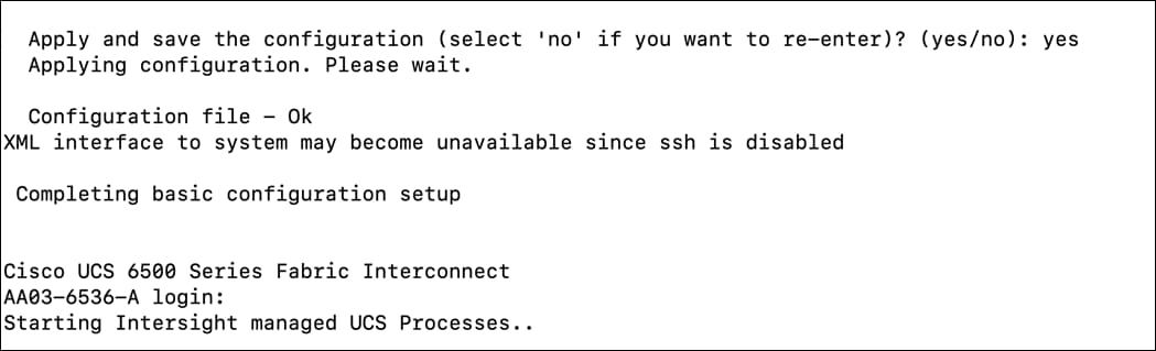
Step 18. Enter yes to apply and save the configuration
Step 19. Wait for the login prompt for Cisco UCS Fabric Interconnect A before proceeding to the next section.
Procedure 2. Configure Cisco UCS to use in a FlashStack Environment
Cisco UCS Fabric Interconnect B
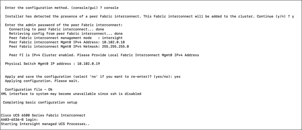
Step 1. Connect to the console port on the second Cisco UCS Fabric Interconnect.
Step 2. Power up the Fabric Interconnect.
Step 3. When the unconfigured system boots, it prompts you for the setup method to be used. Enter console to continue the initial setup using the console CLI.
Step 4. Enter yes to add to the existing cluster.
Step 5. Provide the peer fabric interconnect details.
Step 6. Enter management IP.
Step 7. Enter yes to apply the configuration.
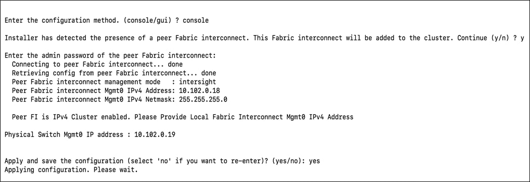
Step 8. Wait for the login prompt for Cisco UCS Fabric Interconnect B before proceeding to the next section.
In this procedure, using the unique device information for the Cisco UCS, you set up a new Cisco Intersight account. You can also select to add the Cisco UCS devices set up for Cisco Intersight managed mode to an existing Cisco Intersight account.
Procedure 1. Set up Cisco Intersight Account
Step 1. Open a browser to Cisco Intersight, https://intersight.com.
Step 2. Click Create an account.
Step 3. Read and accept the license agreement. Click Next.
Step 4. Provide an Account Name and click Create.
Step 5. With a successful creation of the Cisco Intersight account, the following page displays:
Note: You can also select to add the Cisco UCS FIs to an existing Cisco Intersight account.
Procedure 2. Set up Cisco Intersight Licensing
Step 1. Log into the Cisco Smart Licensing portal: https://software.cisco.com/software/smart-licensing/alerts.
Step 2. Verify that the correct virtual account is selected.
Step 3. Under Inventory > General, generate a new token for product registration.
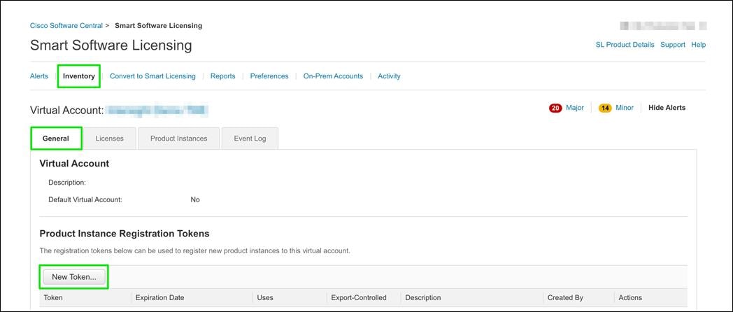
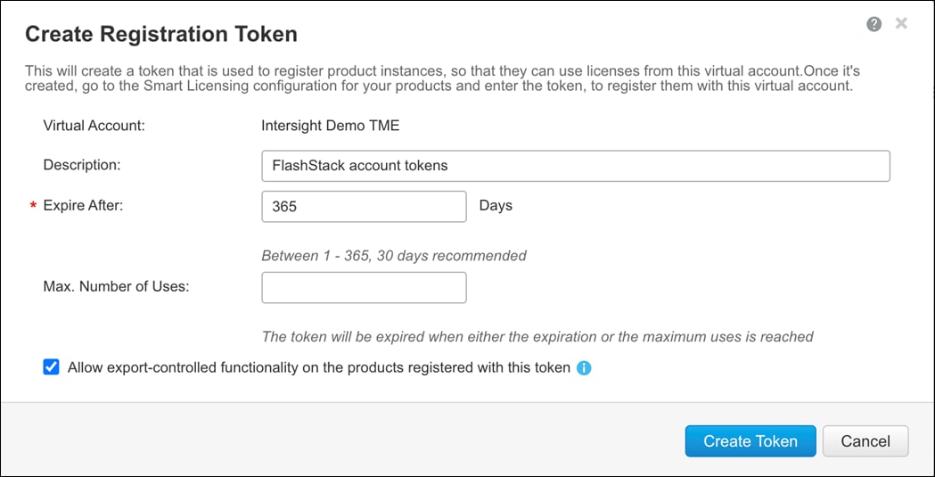
Step 4. Copy this newly created token.
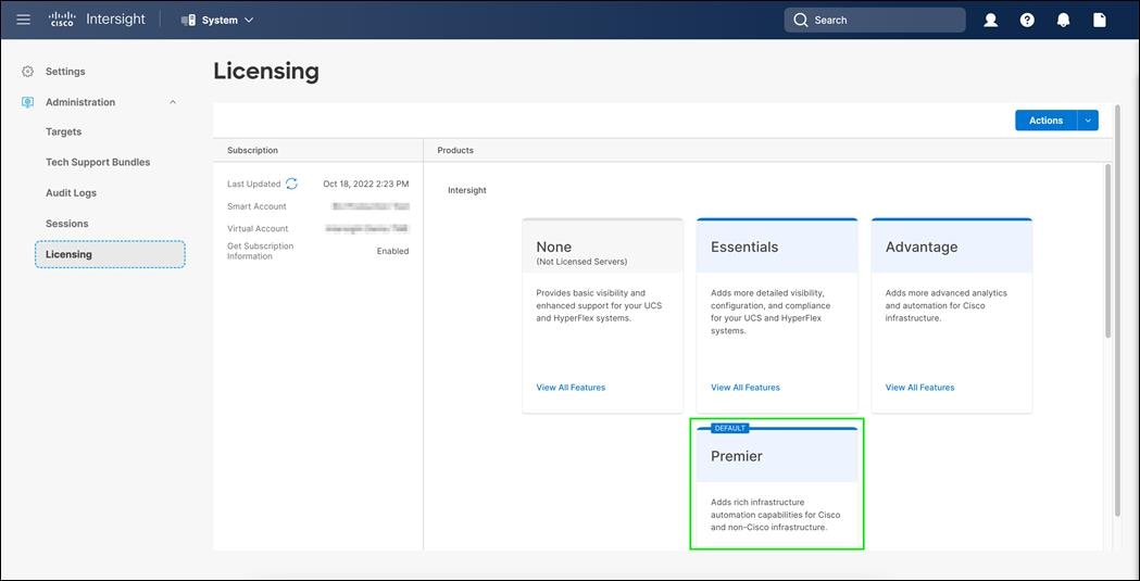
Step 5. In Cisco Intersight, Select System from Service Selector.
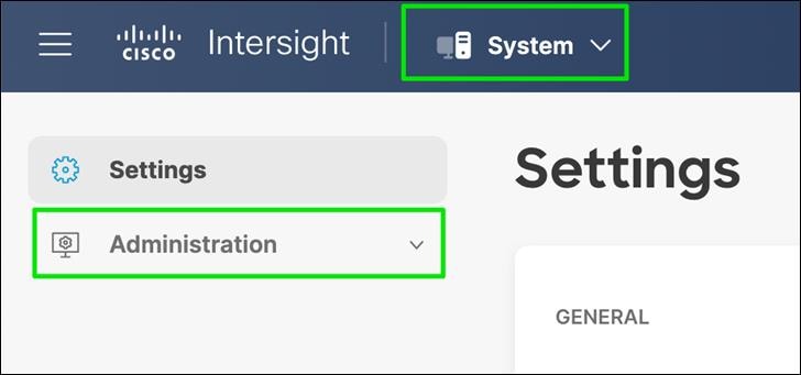
Step 6. From the left navigation pane, select Administration > Licensing.
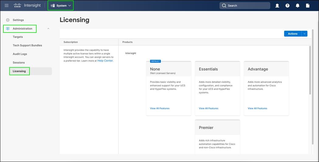
Step 7. Click on Action and select Register.
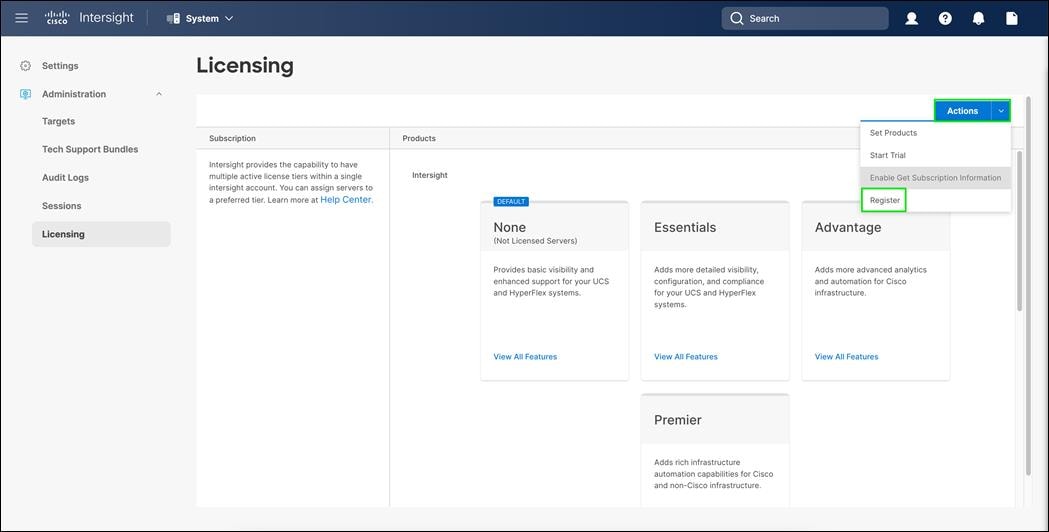
Step 8. Enter the product instance registration token copied from smart licensing and click Next.
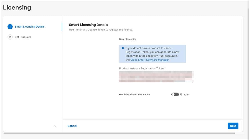
Step 9. Select the Licensing Tier.
Step 10. Enable Workload Optimizer if you select.
Step 11. Click on Register.
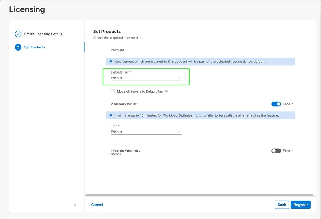
Step 12. Make sure licensing is applied correct.
Procedure 3. Set Up Cisco Intersight Resource Group
In this procedure, a Cisco Intersight resource group is created where resources such as targets will be logically grouped. In this deployment, a single resource group is created to host all the resources, but customers can select to create multiple resource groups for granular control of the resources.
Step 1. Open a browser to Cisco Intersight, https://intersight.com.
Step 2. From Service Selector, select System.
Step 3. From the left navigation pane, click Settings.

Step 4. Click Resource Groups in the middle panel.
Step 5. Click + Create Resource Group in the top-right corner.
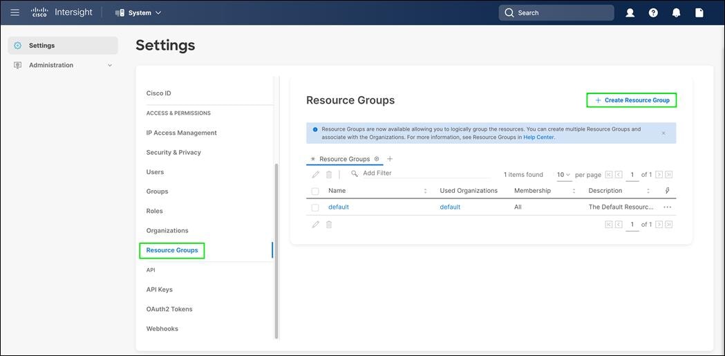
Step 6. Provide a name for the Resource Group (for example, FlashStack-rg).
Step 7. Under Memberships, select Custom.
Step 8. Click Create.
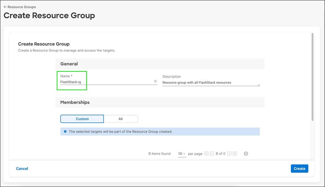
Procedure 4. Set Up Cisco Intersight Organization
Step 1. Open a browser to Cisco Intersight, https://intersight.com.
Step 2. From Service Selector, select System.
Step 3. From the left navigation pane, select Settings.
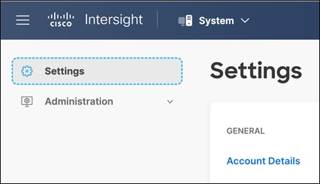
Step 4. Click Organizations in the middle panel.
Step 5. Click + Create Organization in the top-right corner.
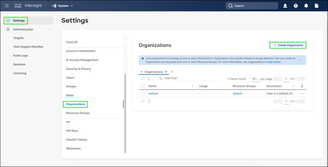
Step 6. Provide a name for the organization (for example, FlashStack).
Step 7. Select the Resource Group created in the last step (for example, FlashStack-rg).
Step 8. Click Create.
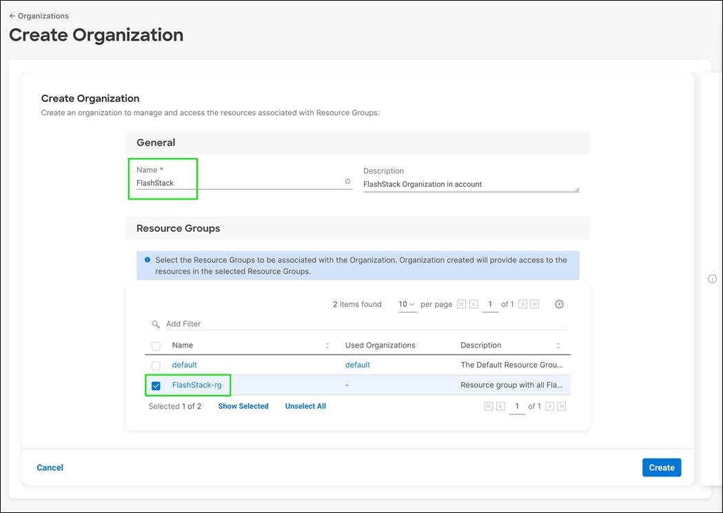
Procedure 5. Claim Cisco UCS Fabric Interconnects in Cisco Intersight
After completing the initial configuration for the fabric interconnects, log into Fabric Interconnect A using your web browser to capture the Cisco Intersight connectivity information.
Step 1. Use the management IP address of Fabric Interconnect A to access the device from a web browser and the previously configured admin password to log into the device.
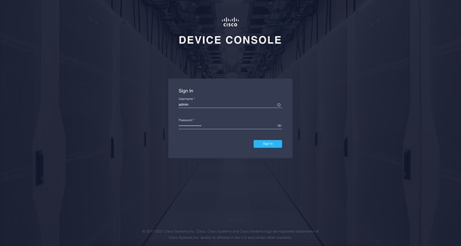
Step 2. Verify both fabric interconnects are healthy and shows correct information
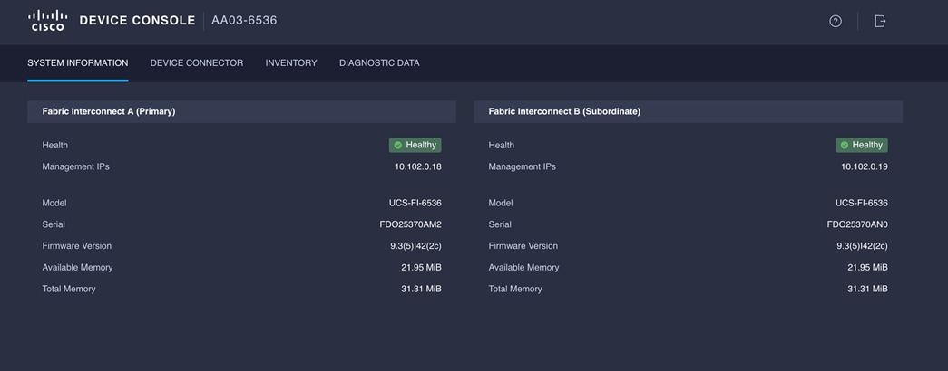
Step 3. Under DEVICE CONNECTOR, you should see the current device status as “Not claimed.” Note, or copy, the Device ID, and Claim Code information to use to set up a new Cisco Intersight account.
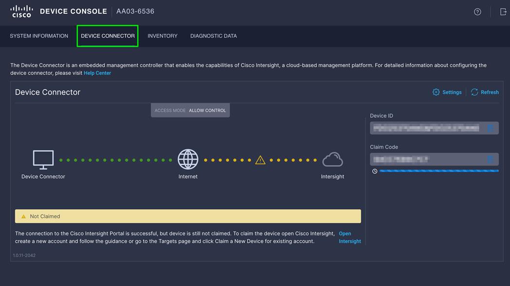
Note: The Device ID and Claim Code information can also be used to claim the Cisco UCS devices set up with Cisco Intersight managed mode in an existing Cisco Intersight account.
Step 4. Open a browser to Cisco Intersight, https://intersight.com.
Step 5. From Service Selector, go to System > Administration.
Step 6. From the left navigation pane, click Targets.
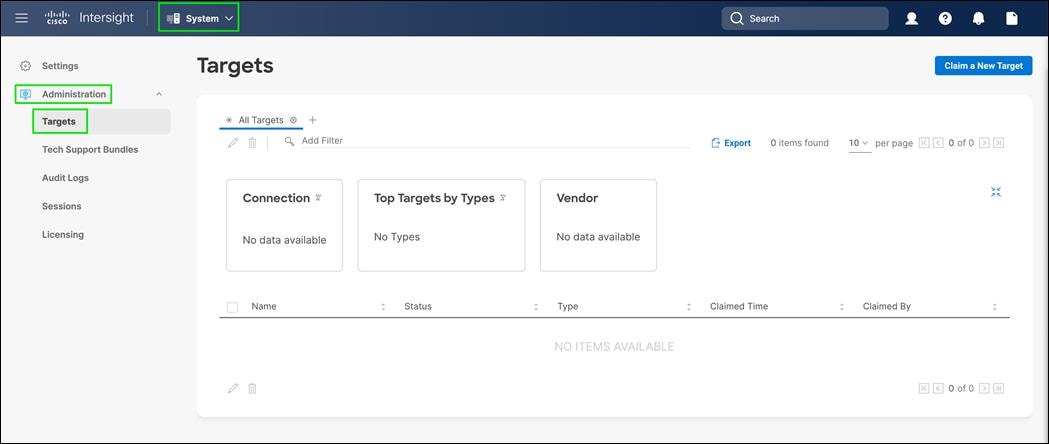
Step 7. Click on Claim a new target.
Step 8. Select Cisco UCS Domain (Intersight Managed) and click Start.
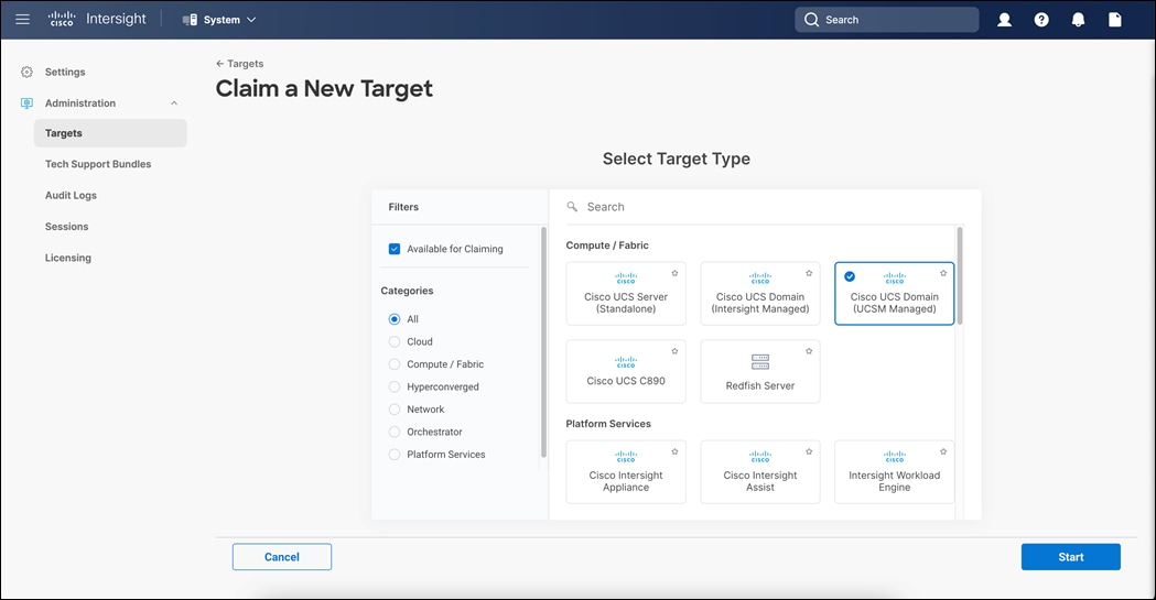
Step 9. Copy and paste the Device ID and Claim from the Cisco UCS FI to Intersight.
Step 10. Select the previously created Resource Group and click Claim.
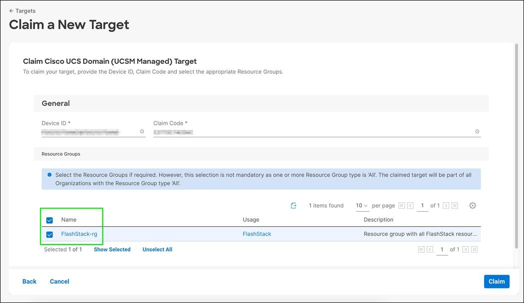
Step 11. On a successful device claim, Cisco UCS FI should appear as a target in Cisco Intersight.
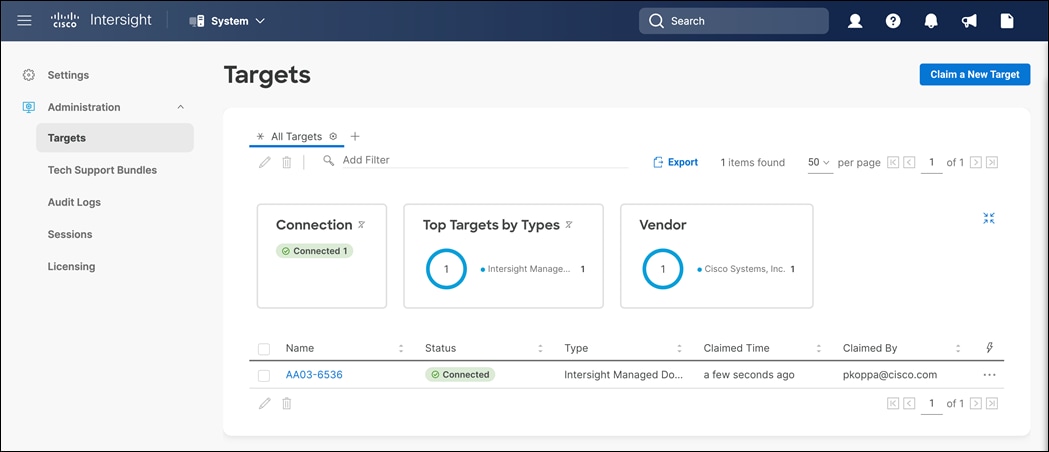
Step 12. Log into the web GUI of the Cisco UCS fabric interconnect and click the browser refresh button.
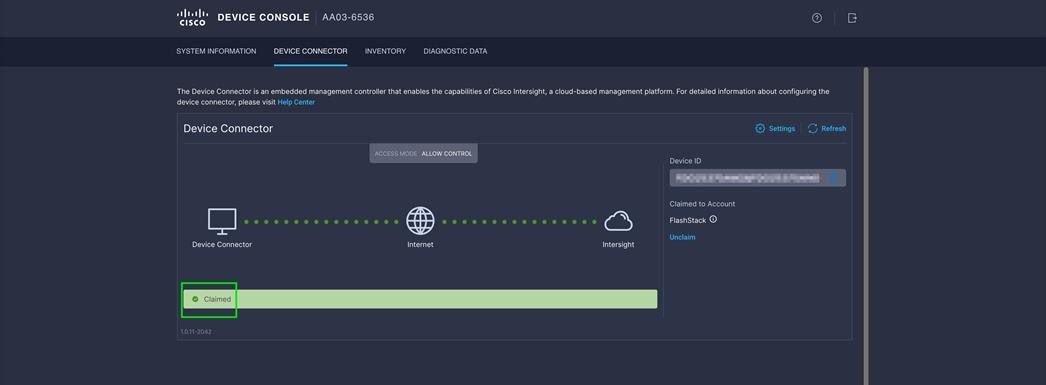
Upgrade Cisco UCS Fabric Interconnect Firmware using Cisco Intersight
Note: If your Cisco UCS 6536 Fabric Interconnects are not already running firmware release 4.2(2c) (NX-OS version 9.3(5)I42(2c)), upgrade them to 4.2(2c).
Note: If Cisco UCS Fabric Interconnects were upgraded to the latest recommended software using Cisco UCS Manager, this upgrade process through Intersight will still work and will copy the Cisco X-Series firmware to the Fabric Interconnects.
Procedure 1. Upgrade fabric interconnect firmware using Cisco Intersight
Step 1. Log into the Cisco Intersight portal.
Step 2. At the top, using the pulldown select Infrastructure Service and then select Fabric Interconnects under Operate on the left.
Step 3. Click the three dots “…” at the end of the row for either of the Fabric Interconnects and select Upgrade Firmware.
Step 4. Click Start.
Step 5. Verify the Fabric Interconnect information and click Next.
Step 6. Enable Advanced Mode using the toggle switch and uncheck Fabric Interconnect Traffic Evacuation.
Step 7. Select 4.2(2c) release from the list and click Next.
Step 8. Verify the information and click Upgrade to start the upgrade process.
Step 9. Keep an eye on the Request panel of the main Intersight screen as the system will ask for user permission before upgrading each FI. Click on the Circle with Arrow and follow the prompts on screen to grant permission.
Step 10. Wait for both the FIs to successfully upgrade.
Configure a Cisco UCS Domain Profile
A Cisco UCS domain profile configures a fabric interconnect pair through reusable policies, allows configuration of the ports and port channels, and configures the VLANs and VSANs in the network. It defines the characteristics of and configures ports on fabric interconnects. The domain-related policies can be attached to the profile either at the time of creation or later. One Cisco UCS domain profile can be assigned to one fabric interconnect domain.
Procedure 1. Create a Cisco UCS Domain Profile
Step 1. Log into the Cisco Intersight portal.
Step 2. From Service Selector, select Infrastructure Service.
Step 3. From the left navigation pane, select Profiles.
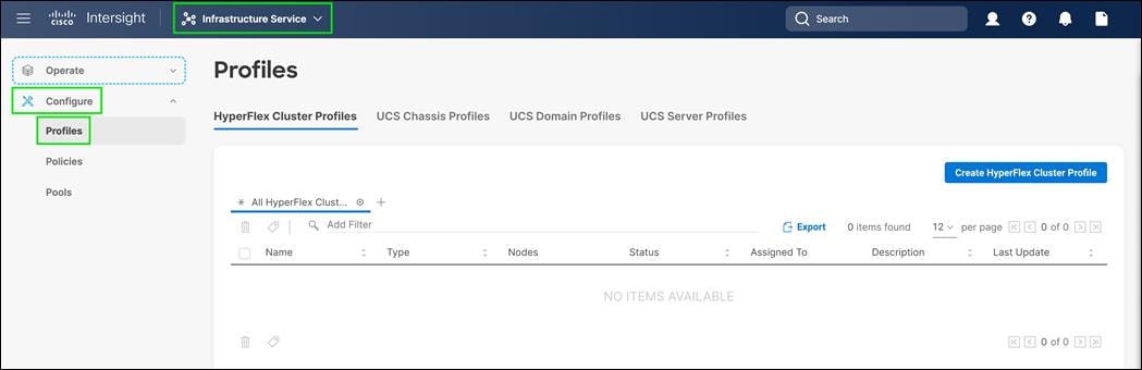
Step 4. In the main window, select UCS Domain Profiles and click Create UCS Domain Profile.
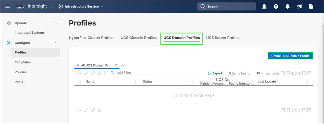
Step 5. On the Create UCS Domain Profile screen, click Start.
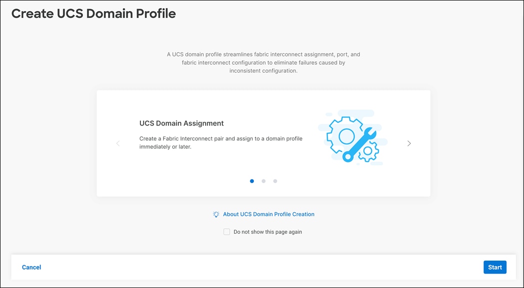
Procedure 2. General Configuration
Step 1. Select the organization from the drop-down list (for example, FlashStack).
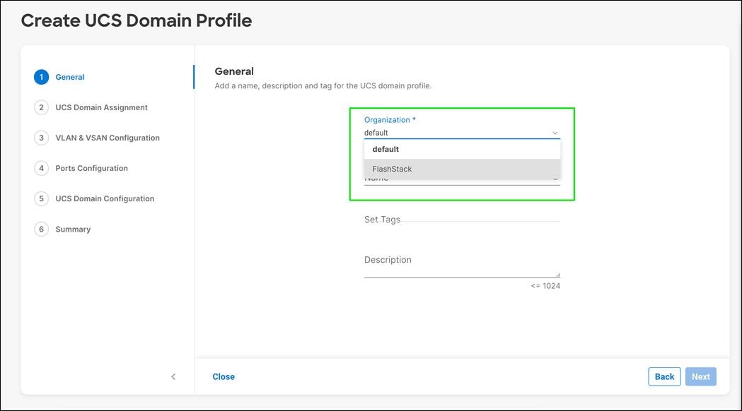
Step 2. Provide a name for the domain profile (for example, AA03-6536-Domain-Profile).
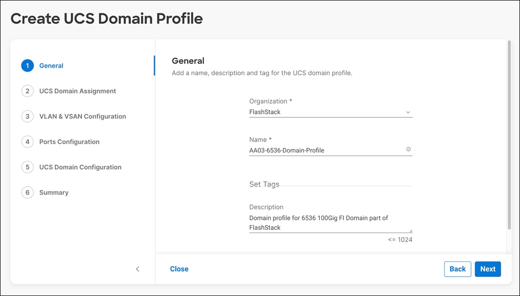
Step 3. Click Next.
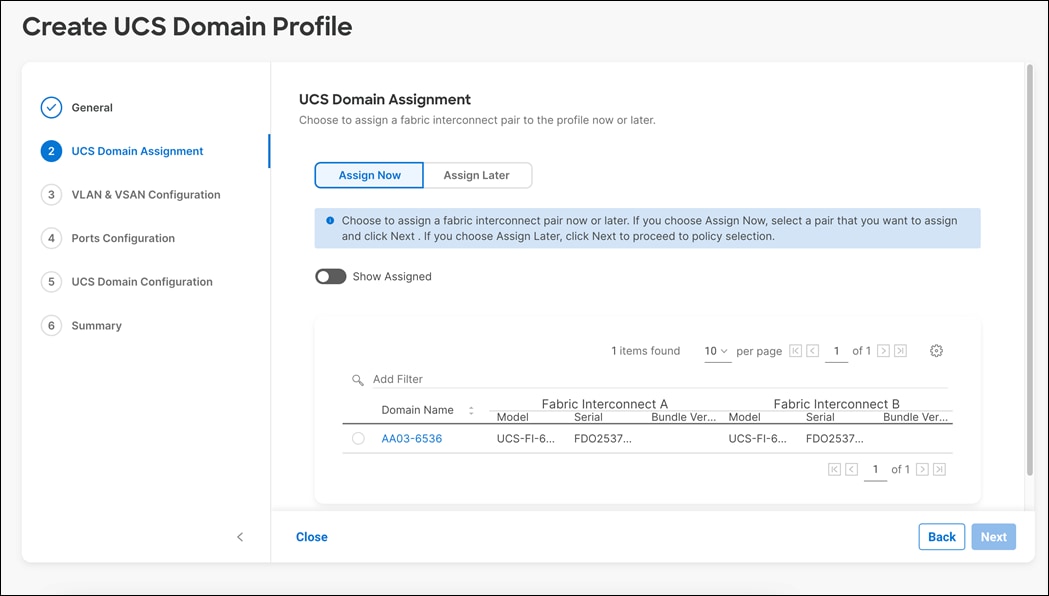
Procedure 3. Cisco UCS Domain Assignment
Step 1. Assign the Cisco UCS domain to this new domain profile by clicking Assign Now and selecting the previously added Cisco UCS domain.
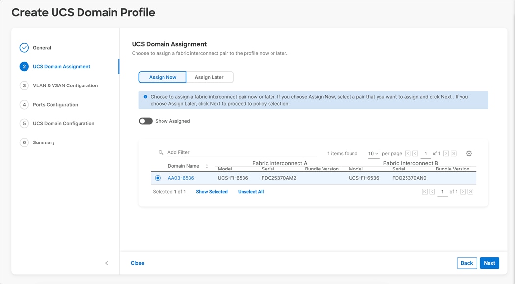
Step 2. Click Next.
VLAN and VSAN Configuration
In this procedure, a single VLAN policy will be created for both FIs, but individual policies will be created for the VSANs as the VSAN IDs are unique for each FI.
Procedure 1. Create and apply the VLAN Policy
Step 1. Click Select Policy next to VLAN Configuration under Fabric Interconnect A.
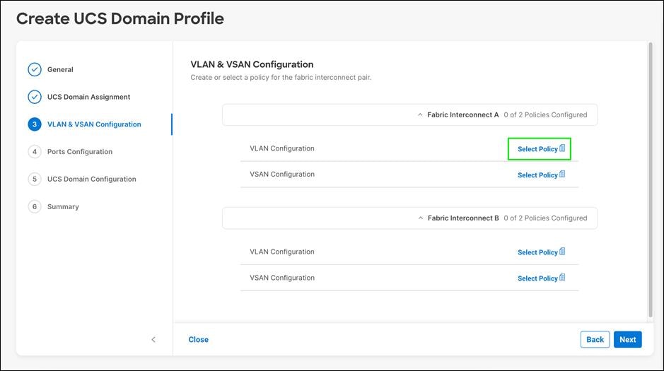
Step 2. In the pane on the right, click Create New.
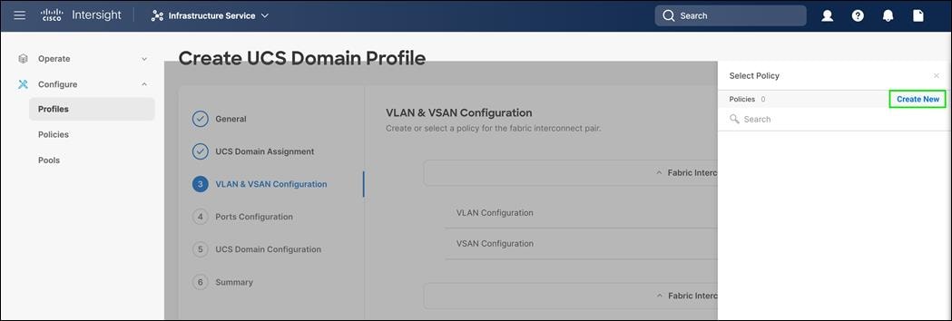
Step 3. Verify the correct organization is selected from the drop-down list (for example, FlashStack) and provide a name for the policy (for example, AA03-6536-VLAN).
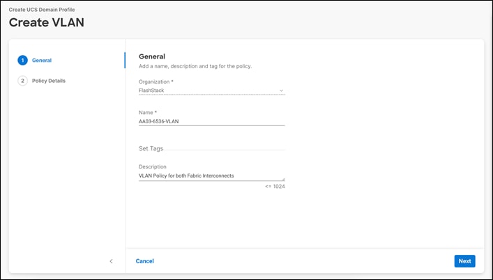
Step 4. Click Next
Step 5. Click Add VLANs.
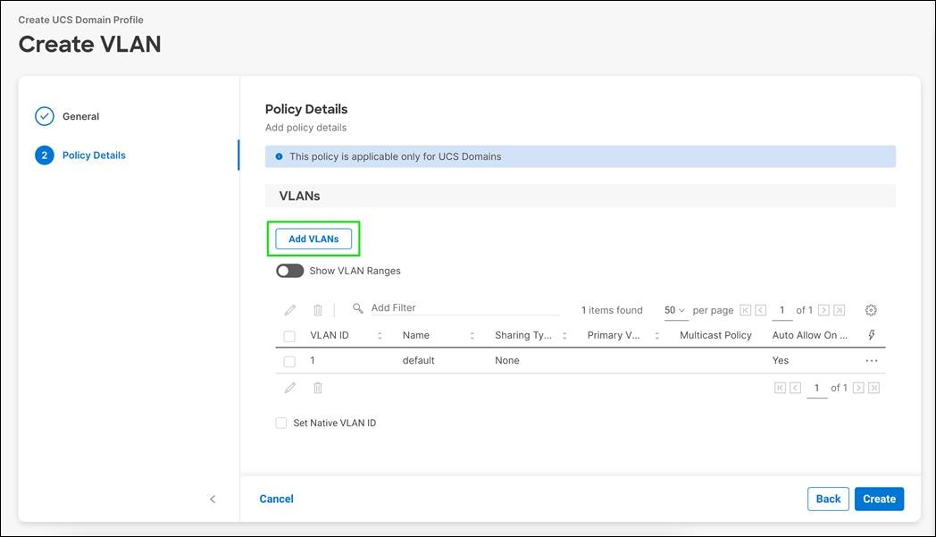
Step 6. Provide a name and VLAN ID for the native VLAN.
Step 7. Make sure Auto Allow On Uplinks is enabled.
Step 8. To create the required Multicast policy, click Select Policy under Multicast Policy*.
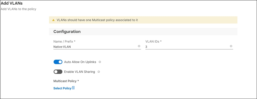
Step 9. In the window on the right, Click Create New to create a new Multicast Policy
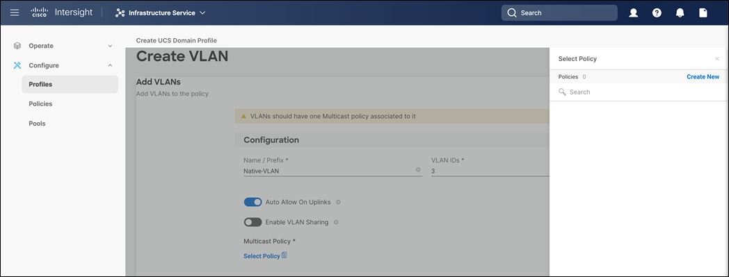
Step 10. Provide a Name for the Multicast Policy (for example, AA03-MCAST).
Step 11. Click Next
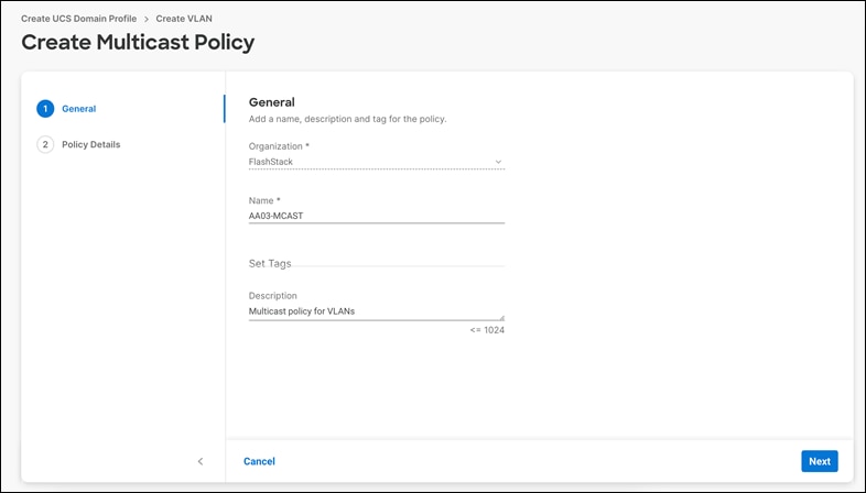
Step 12. Leave the Snooping State selected and click Create.
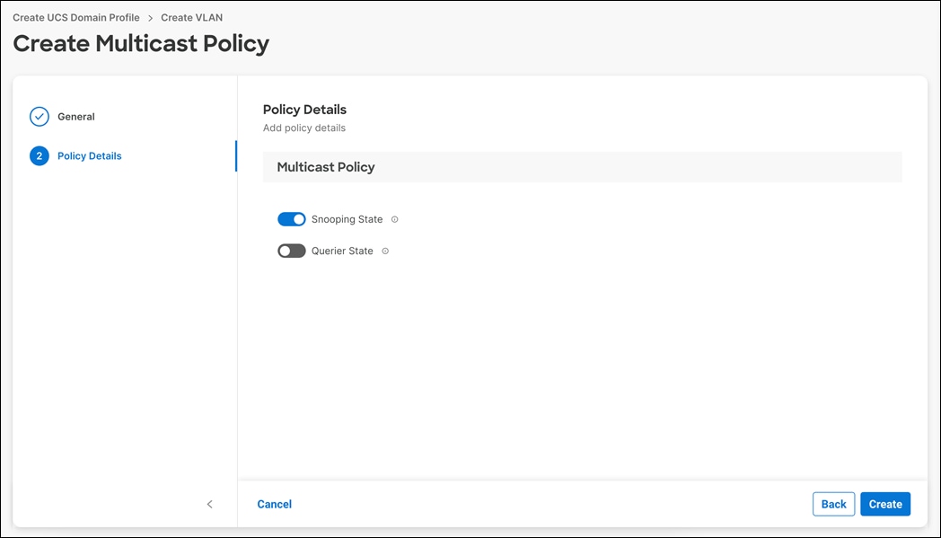
Step 13. Click Add to add the VLAN.
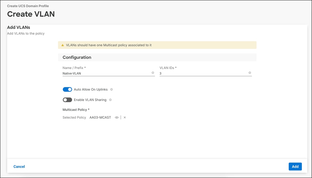
Step 14. Select Set Native VLAN ID and enter the VLAN number (for example, 3) under VLAN ID.
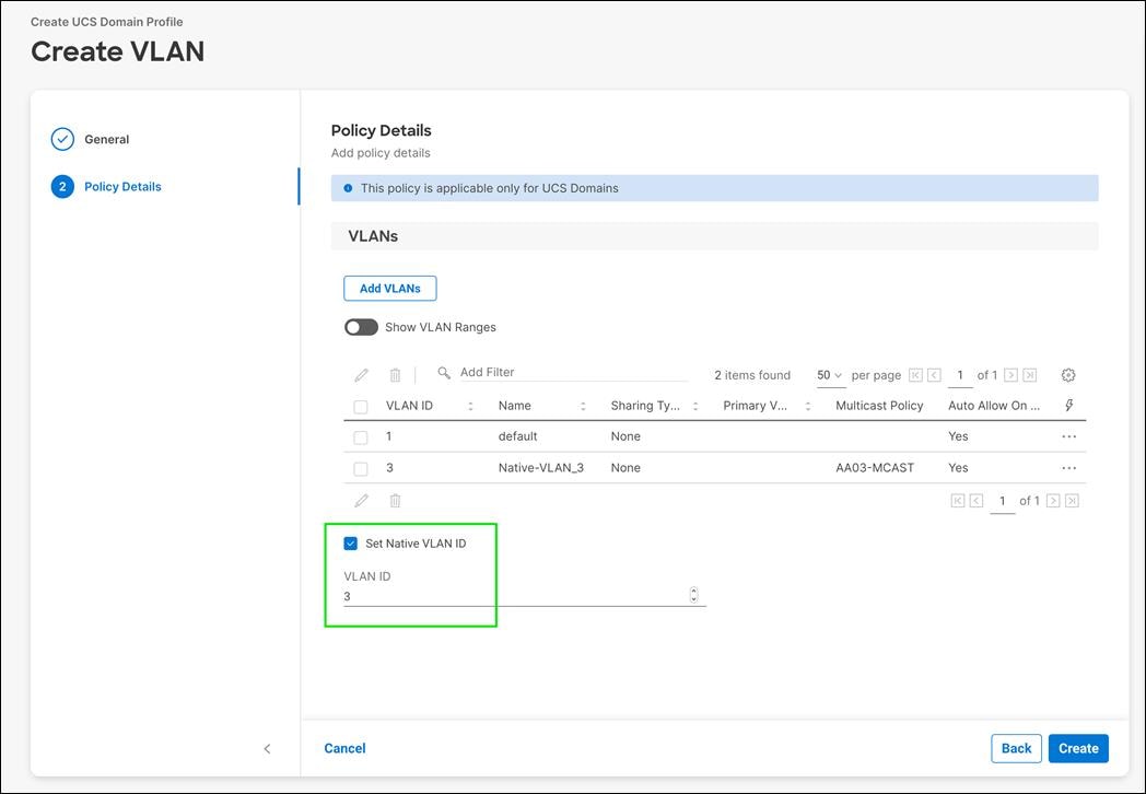
Step 15. Add the remaining VLANs for FlashStack by clicking Add VLANs and entering the VLANs one by one. Reuse the previously created multicast policy for all the VLANs.
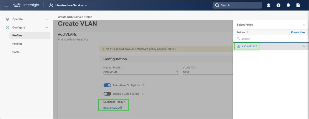
Step 16. The VLANs created during this validation are shown in the screen image below:
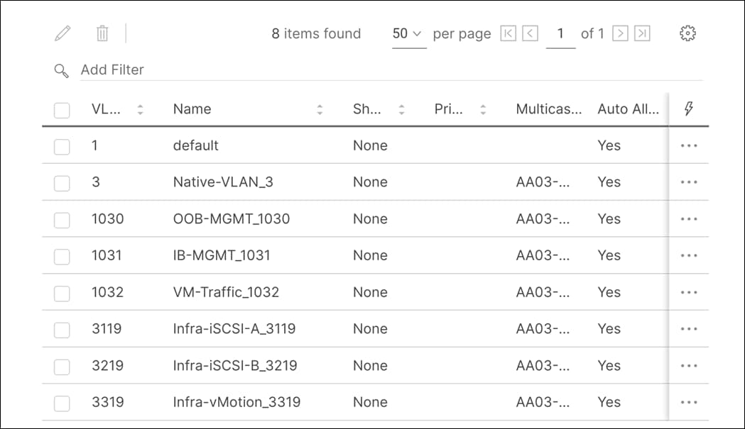
Step 17. Click Create at bottom right to finish creating the VLAN policy and associated VLANs.
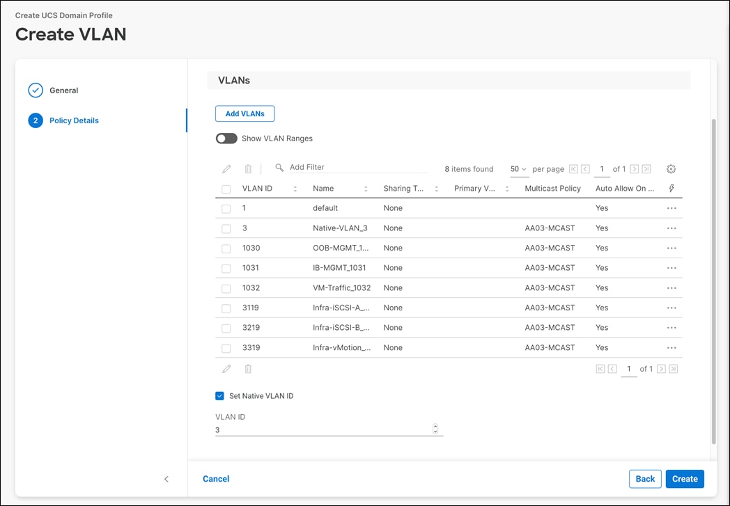
Step 18. Click Select Policy next to VLAN Configuration for Fabric Interconnect B
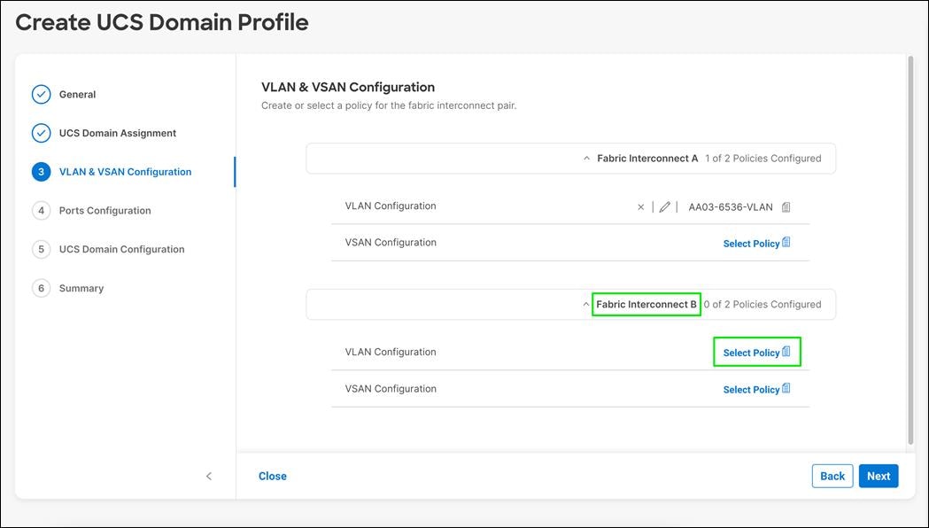
Step 19. Select the same VLAN policy
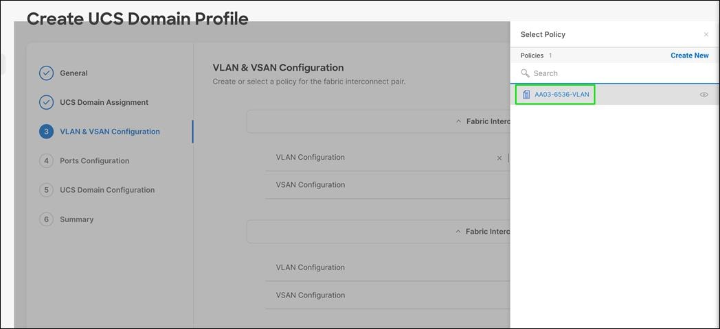
Step 20. Click Select Policy next to VSAN Configuration under Fabric Interconnect A.
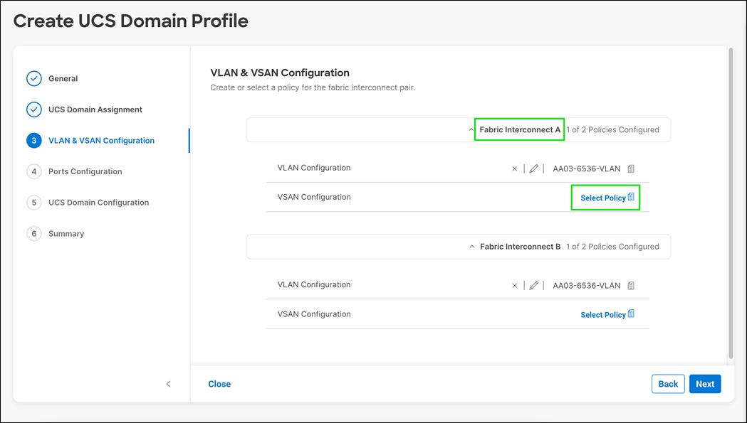
Step 21. In the pane on the right, click Create New.
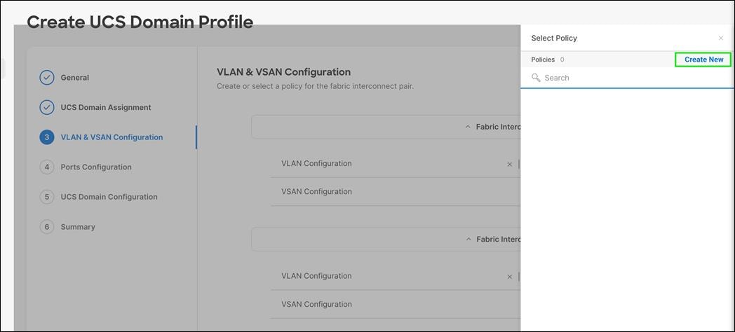
Step 22. Verify the correct organization is selected from the drop-down list (for example, FlashStack) and provide a name for the policy (for example, AA03-6536-VSAN-Pol-A).
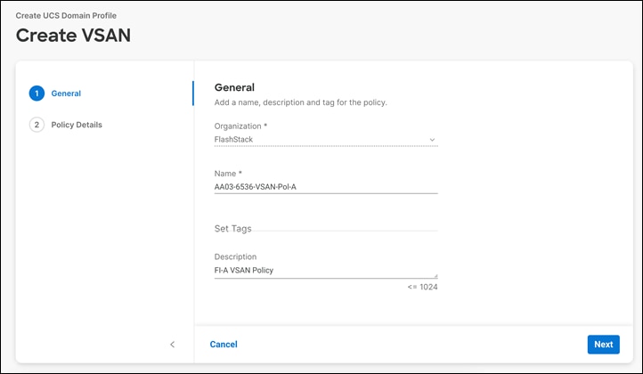
Note: A separate VSAN-Policy is created for each fabric interconnect.
Step 23. Click Next.
Step 24. Click Add VSAN.
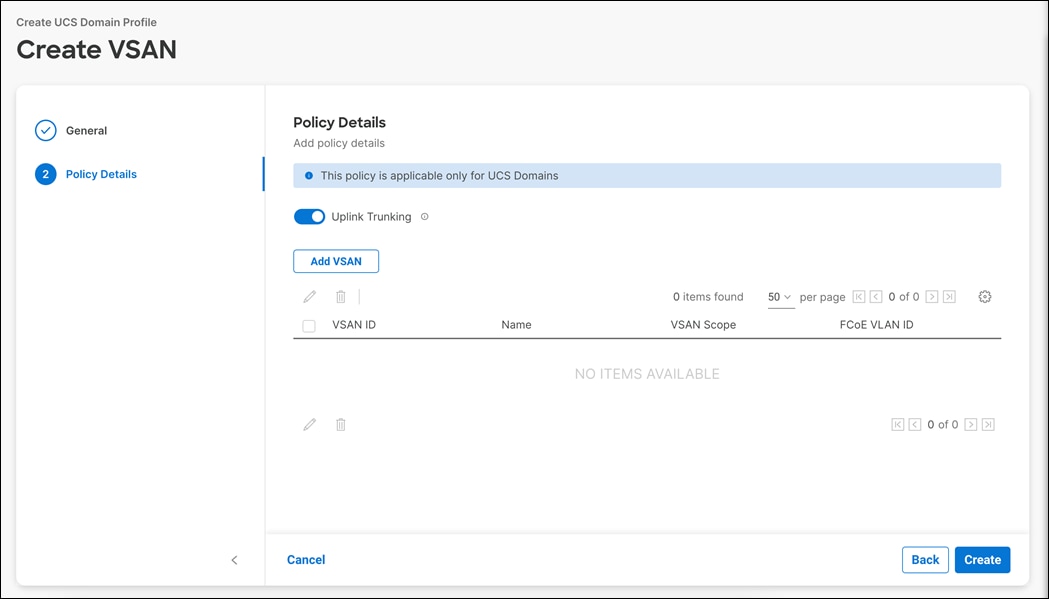
Step 25. Provide a name (for example, VSAN-A), VSAN ID (for example, 103), and associated Fibre Channel over Ethernet (FCoE) VLAN ID (for example, 103) for SAN A.
Step 26. Set VLAN Scope as Uplink
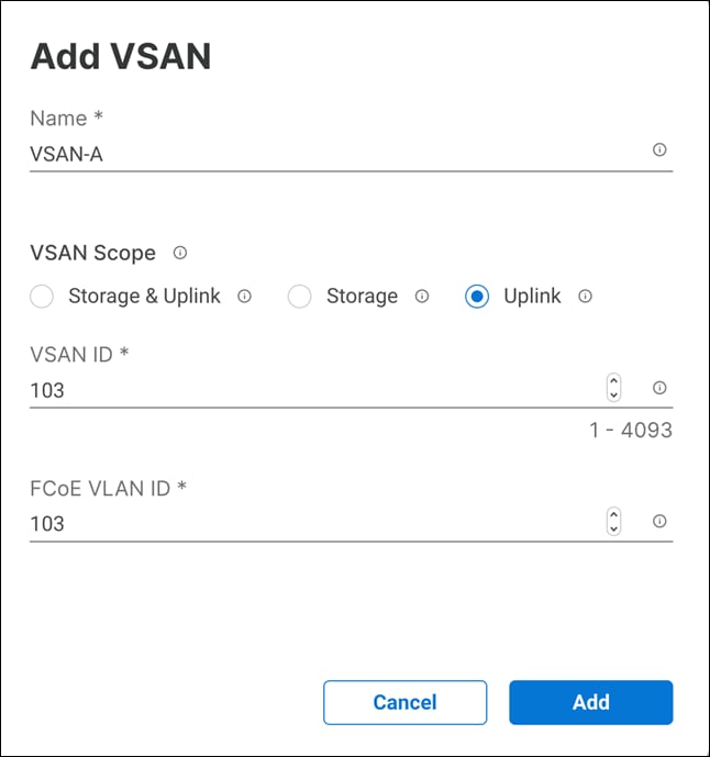
Step 27. Click Add.
Step 28. Click Create to finish creating VSAN policy for fabric A.
Step 29. Click Select Policy next to VSAN Configuration under Fabric Interconnect B
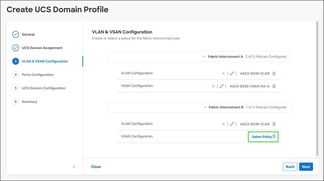
Step 30. In the pane on the right, click Create New.
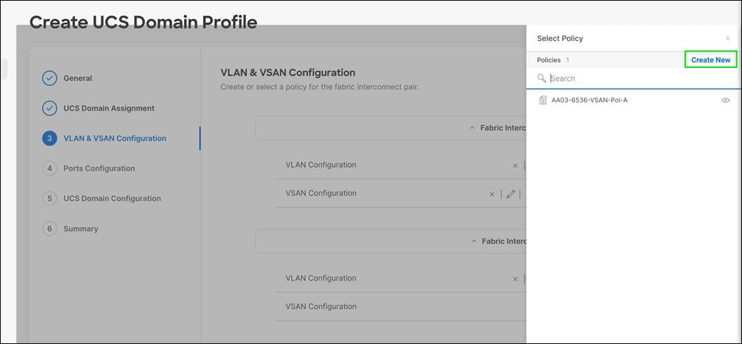
Step 31. Verify the correct organization is selected from the drop-down list (for example, FlashStack) and provide a name for the policy (for example, AA03-6536-VSAN-Pol-B).
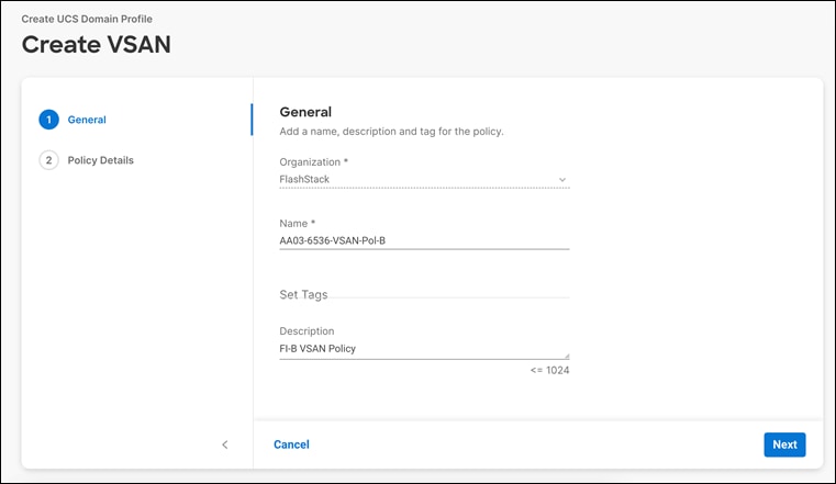
Step 32. Click Next.
Step 33. Click Add VSAN.
Step 34. Provide a name (for example, VSAN-B), VSAN ID (for example, 104), and associated Fibre Channel over Ethernet (FCoE) VLAN ID (for example, 104) for SAN B.
Step 35. Set VLAN Scope as Uplink.
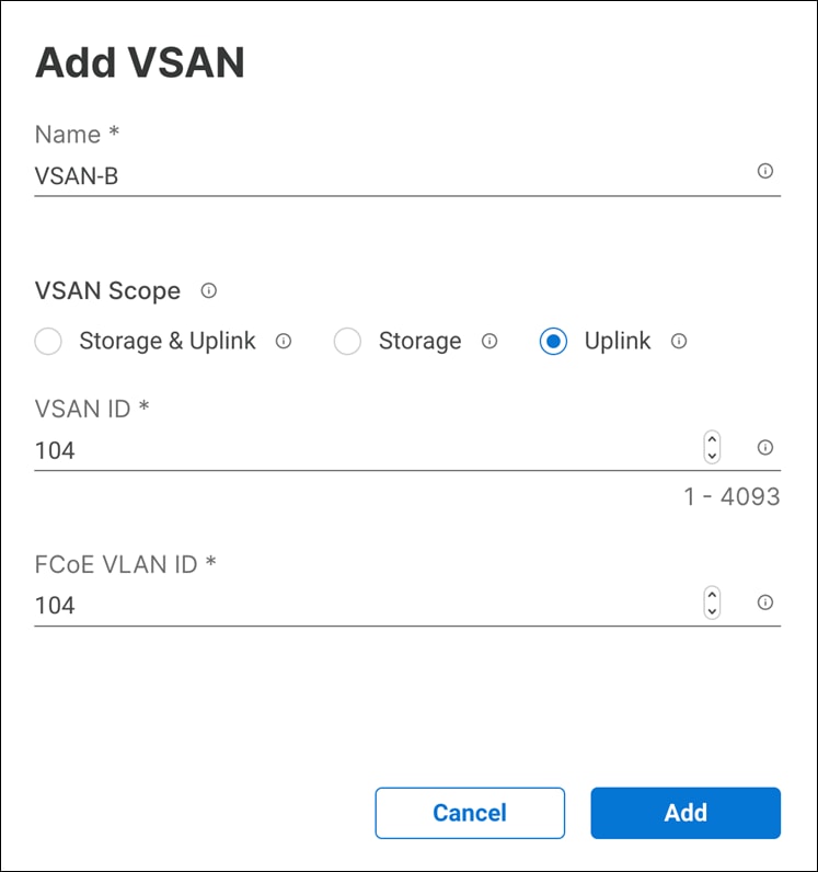
Step 36. Click Add.
Step 37. Click Create to finish creating VSAN policy for fabric A.
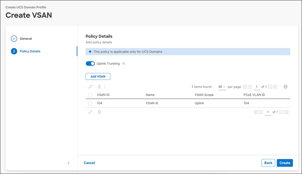
Step 38. Verify that a common VLAN policy and two unique VSAN policies are associated with the two fabric interconnects.
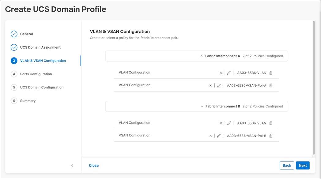
Step 39. Click Next.
Procedure 2. Configure Ports on Fabric Interconnects
Step 1. Click Select Policy for Fabric Interconnect A.
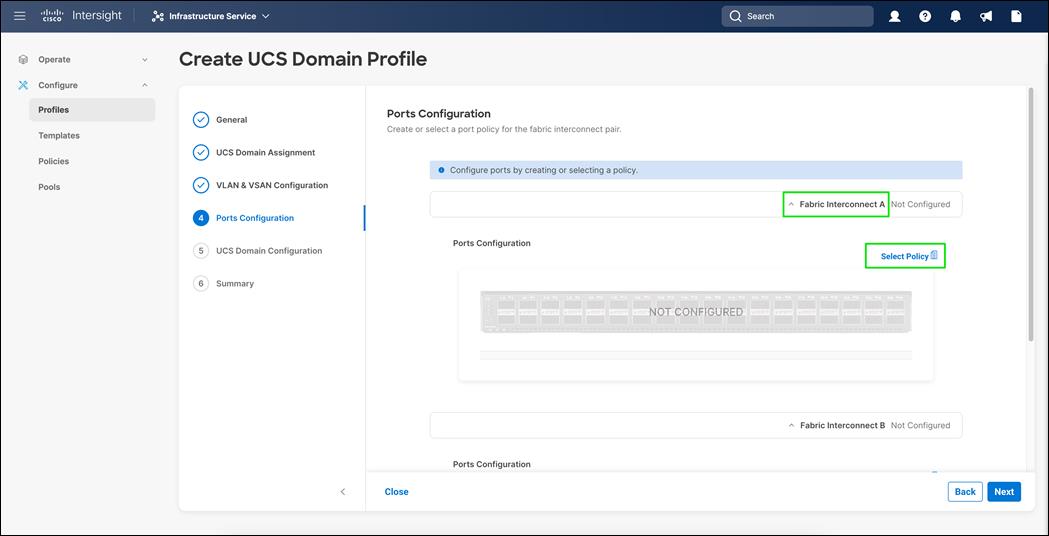
Step 2. Click Create New in the pane on the right to define a new port configuration policy.
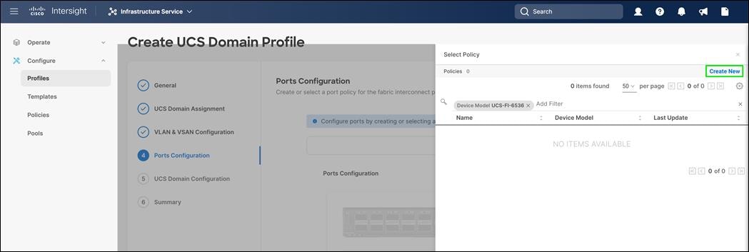
Note: Use two separate port policies for the fabric interconnects. Using separate policies provide flexibility when port configuration (port numbers or speed) differs between the two FIs. When configuring Fibre Channel, two policies are required because each fabric interconnect uses a unique Fibre Channel and VSAN ID.
Step 3. Verify correct organization is selected from the drop-down list (for example, FlashStack) and provide a name for the policy (for example, AA03-6536-PortPol-A).
Step 4. From the drop-down list, select UCS-FI-6536 as the Switch Model.
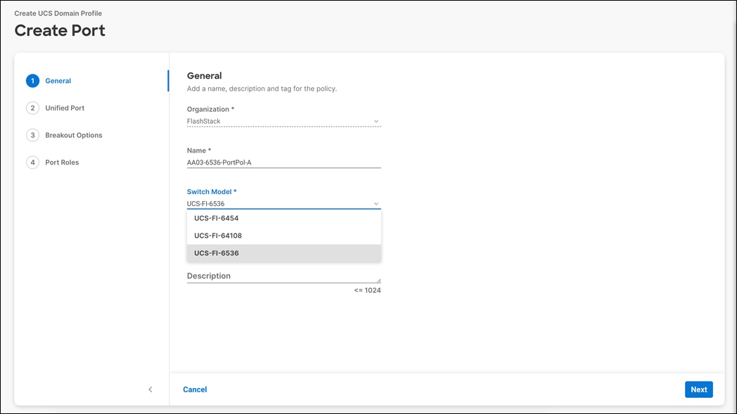
Step 5. Click Next.
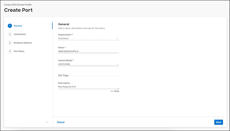
Step 6. Move the slider to set up unified ports.
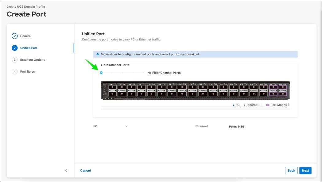
Step 7. In this deployment, the last two ports were selected as Fibre Channel ports as 4x32G breakouts. Click Next.
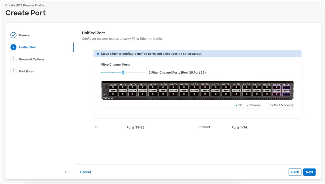
Step 8. Verify the ports 35 and 36 are indeed configured as FC ports.
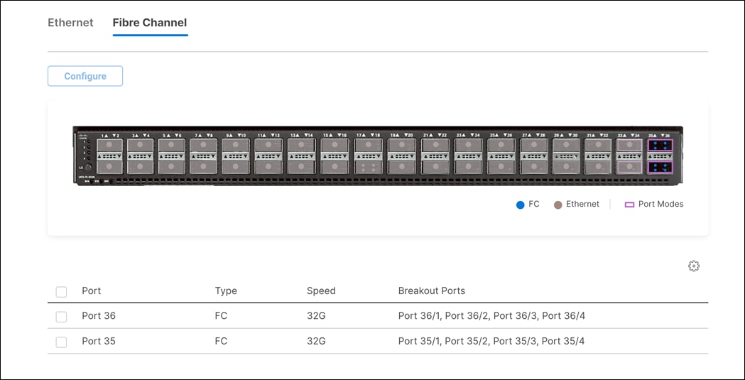
Step 9. If any Ethernet ports need to be configured as breakouts, either 4x25G or 4x10G, for connecting C-Series servers or a UCS 5108 chassis, configure them here. In the list, select the checkbox next to any ports that need to be configured as breakout or select the ports on the graphic. When all ports are selected, click Configure at the top of the window.
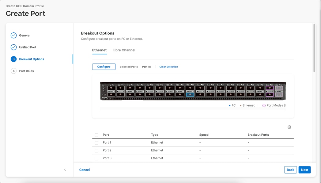
Step 10. In the Set Breakout popup, select either 4x10G or 4x25G and click Set.
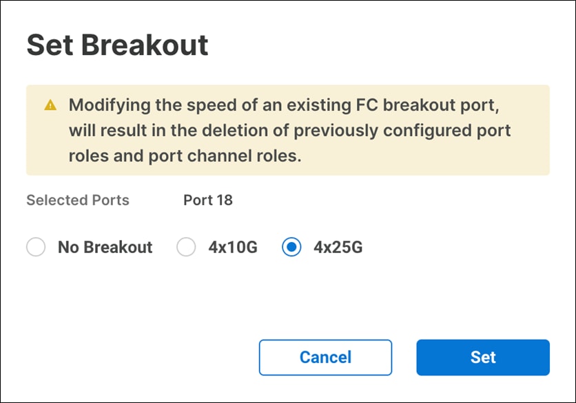
Step 11. Under Breakout Options, select Fibre Channel.
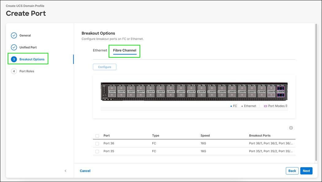
Step 12. Select any ports that need the speed changed from 16G to 32G and click Configure.
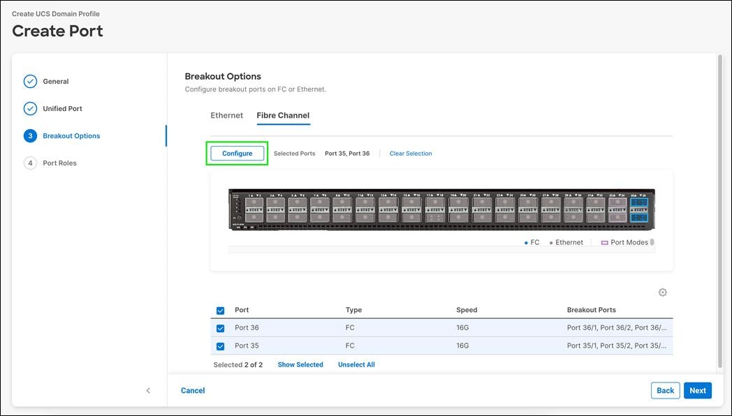
Step 13. In the Set Breakout popup, select 4x32G and click Set.
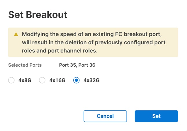
Step 14. Confirm that FC Breakout configuration is done on correct ports
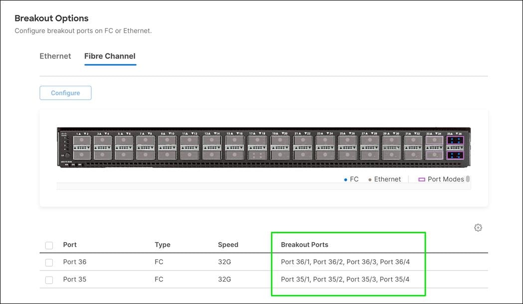
Step 15. Click Next to go to Port Roles configuration.
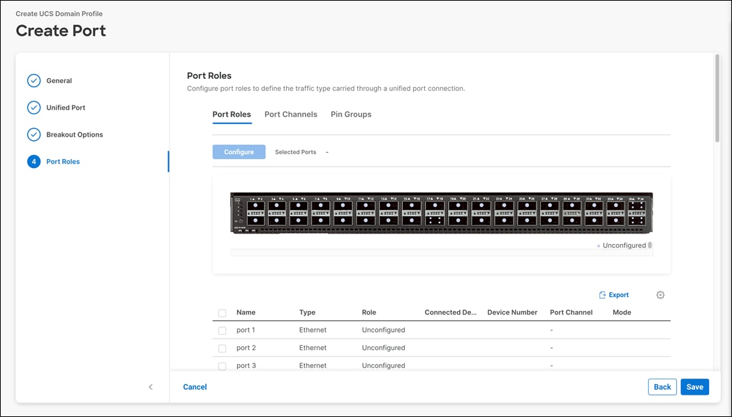
Step 16. In the list, select the checkbox next to any ports that need to be configured as server ports, including ports connected to chassis or C-Series servers. Ports can also be selected on the graphic.
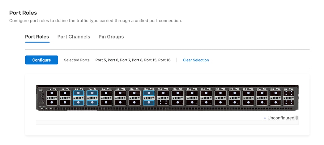
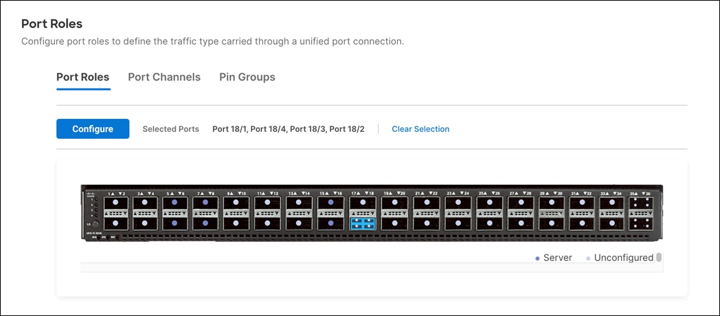
Step 17. When all ports are selected, click Configure. Breakout and non-breakout ports cannot be configured together. If you need to configure breakout and non-breakout ports, do this configuration in two steps.
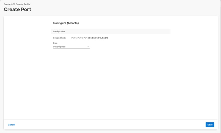
Step 18. From the drop-down list, select Server as the role. Also, unless you are using a Nexus 93180YC-FX3 as a FEX, leave Auto Negotiation enabled. If you need to do manual number of Chassis or C-Series Servers, enable Manual Chassis/Server Numbering.
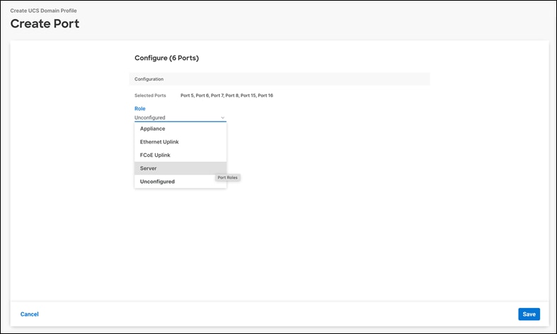
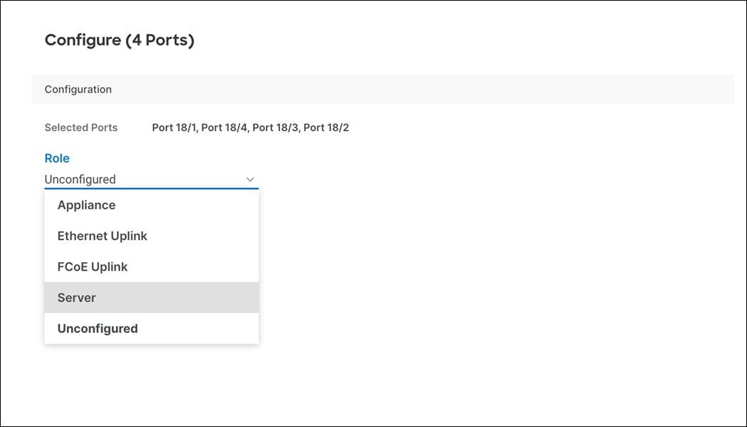
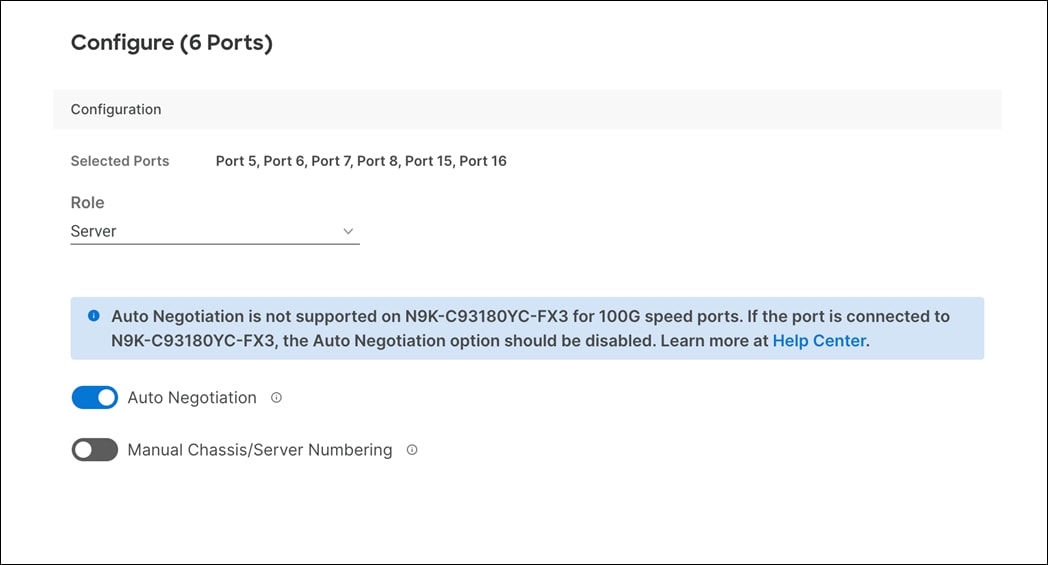
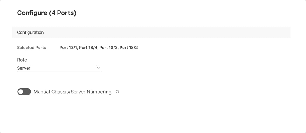
Step 19. Click Save.
Step 20. Configure the Ethernet uplink port channel by selecting Port Channel in the main pane and then clicking Create Port. Channel.
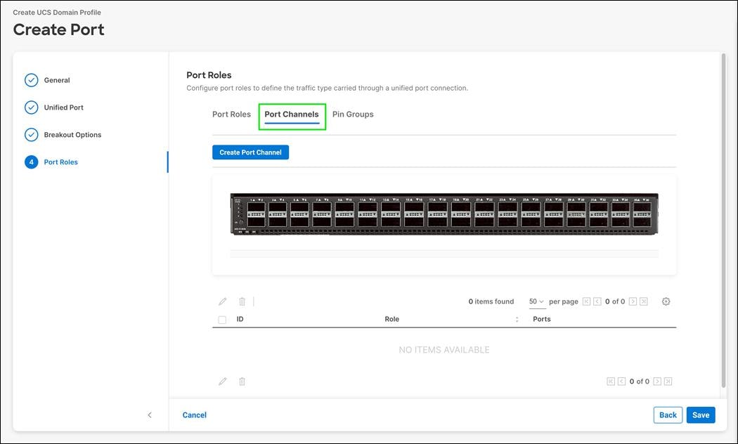
Step 21. Select Ethernet Uplink Port Channel as the role.
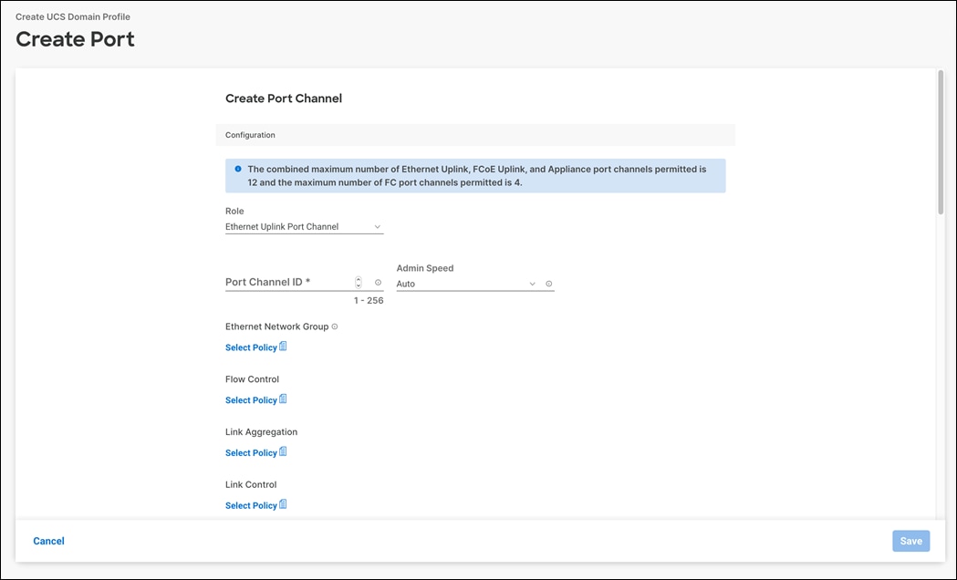
Step 22. Provide a port-channel ID (for example, 11), and select a value for Admin Speed from drop-down list (for example, 100Gbps). If connecting at 100Gbps to either a Nexus 93180YC-FX, 93360YC-FX2, or 93180YC-FX3, auto negotiation is not supported on the ALE ports, and you will need to set a port speed.
Note: You can create the Ethernet Network Group, Flow Control, Link Aggregation for defining disjoint Layer-2 domain or fine tune port-channel parameters. These policies were not used in this deployment and system default values were utilized.
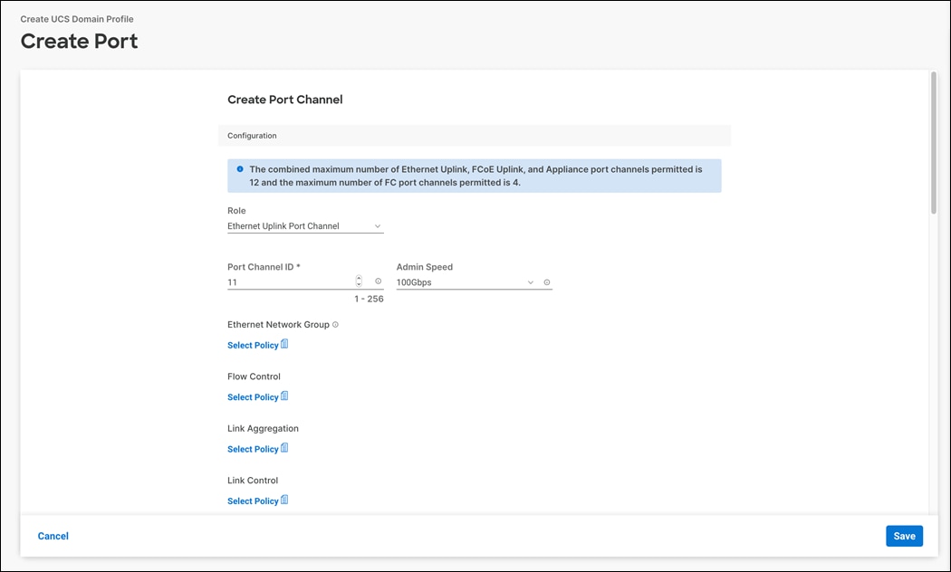
Step 23. Under Link Control, click Select Policy.
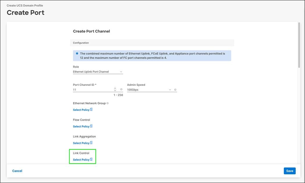
Step 24. In the upper right, click Create New.
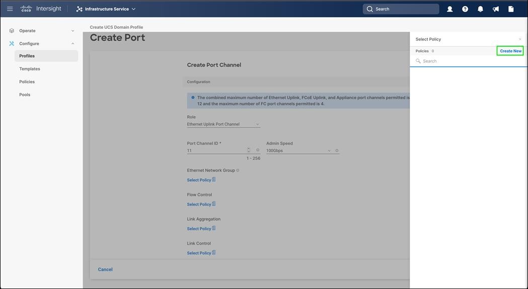
Step 25. Verify the correct organization is selected from the drop-down list (for example, FlashStack) and provide a name for the policy (for example, AA03-UDLD-Link-Control). Click Next.
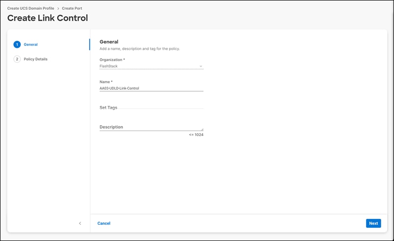
Step 26. Leave the default values selected and click Create.
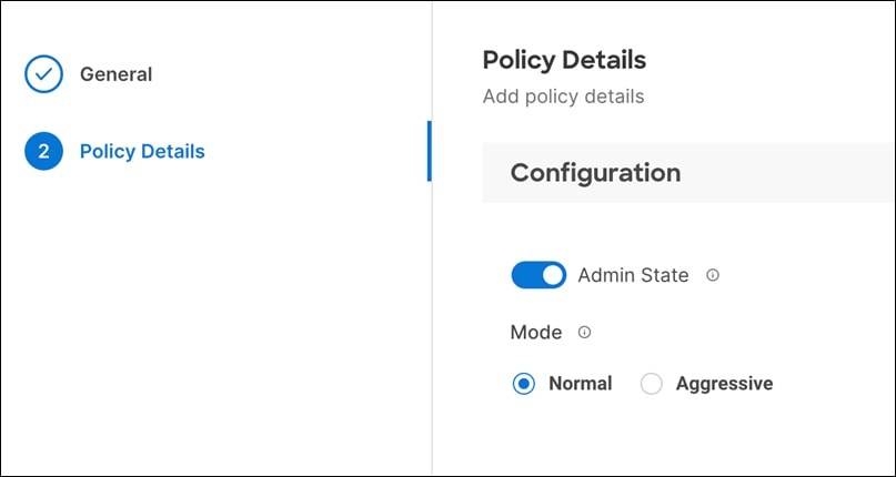
Step 27. Scroll down and select uplink ports from the list of available ports (for example, port 29 and 30).
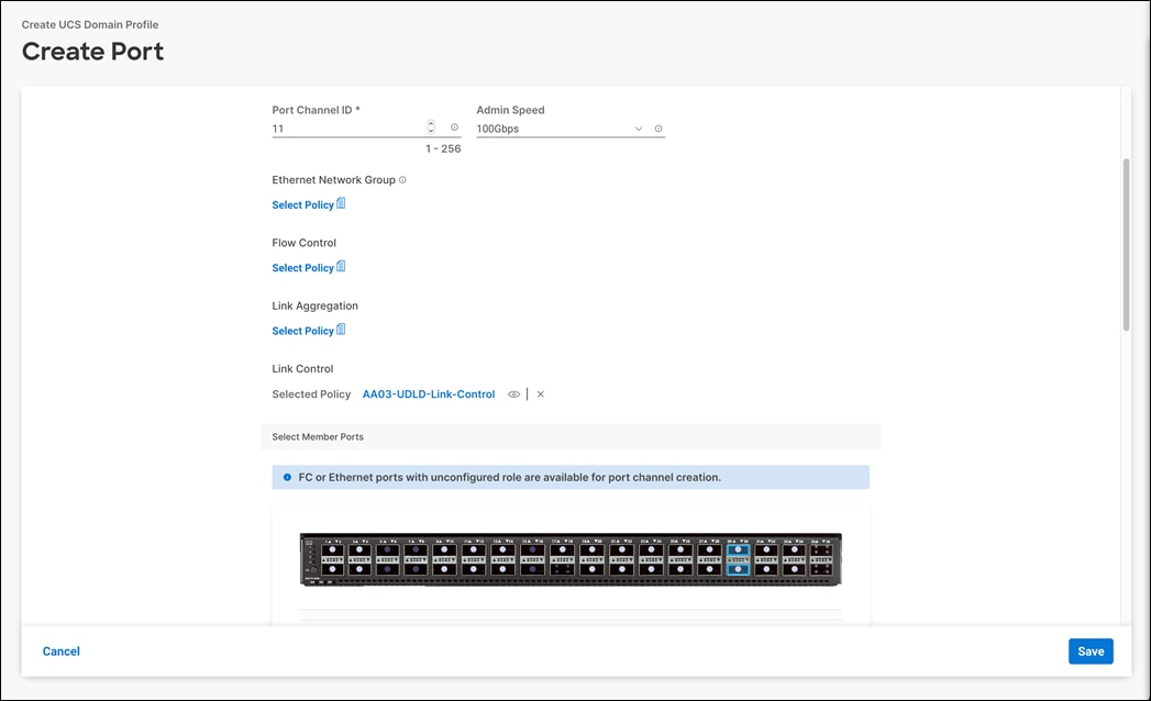
Step 28. Click Save.
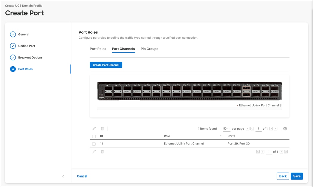
Procedure 3. Configure FC Port Channel (FC configuration only)
FC uplink port channel is only needed when configuring SAN and can be skipped when configuring IP-only storage access.
● Name of the port policy: AA03-Port-Pol-A
● Ethernet port-Channel ID: 11
● FC port-channel ID: 103
● FC VSAN ID: 103
Step 1. Configure a Fibre Channel Port Channel by selecting the Port Channel in the main pane again and clicking Create Port Channel.
Step 2. In the drop-down list under Role, select FC Uplink Port Channel.
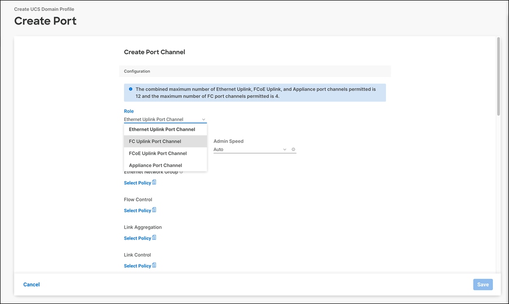
Step 3. Provide a port-channel ID (for example, 103), select a value for Admin Speed (for example, 32Gbps), and provide a VSAN ID (for example, 103).
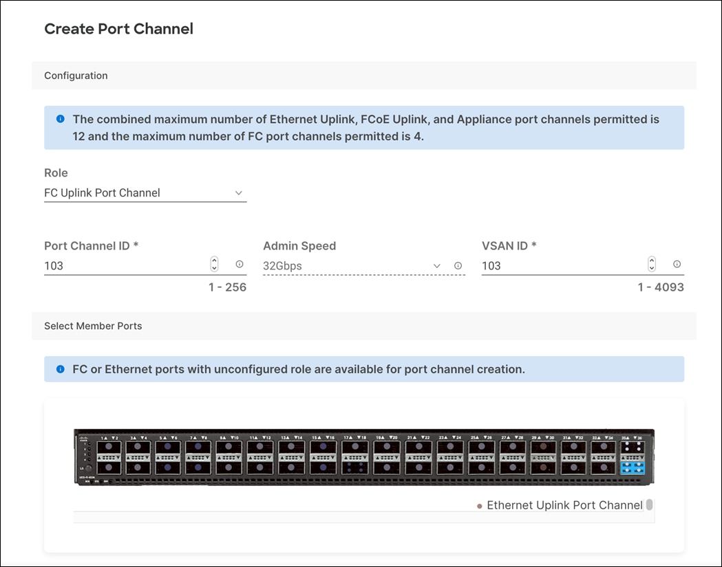
Step 4. Select ports (for example, 36/1,36/2,36/3,36/4).
Step 5. Click Save.
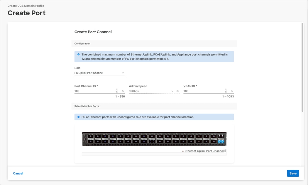
Step 6. Verify the port-channel IDs and ports after both the Ethernet uplink port channel and the Fibre Channel uplink port channel have been created.
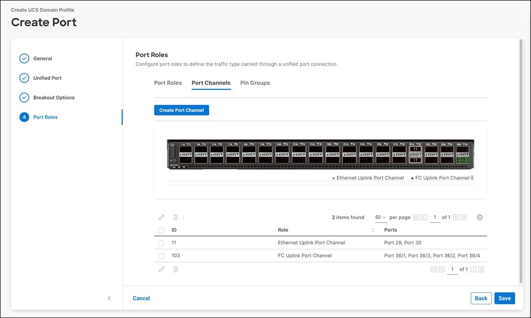
Step 7. Click Save to create the port policy for FI-A. The Summary screen, shown below, can be used to verify ports were selected and configured correctly.
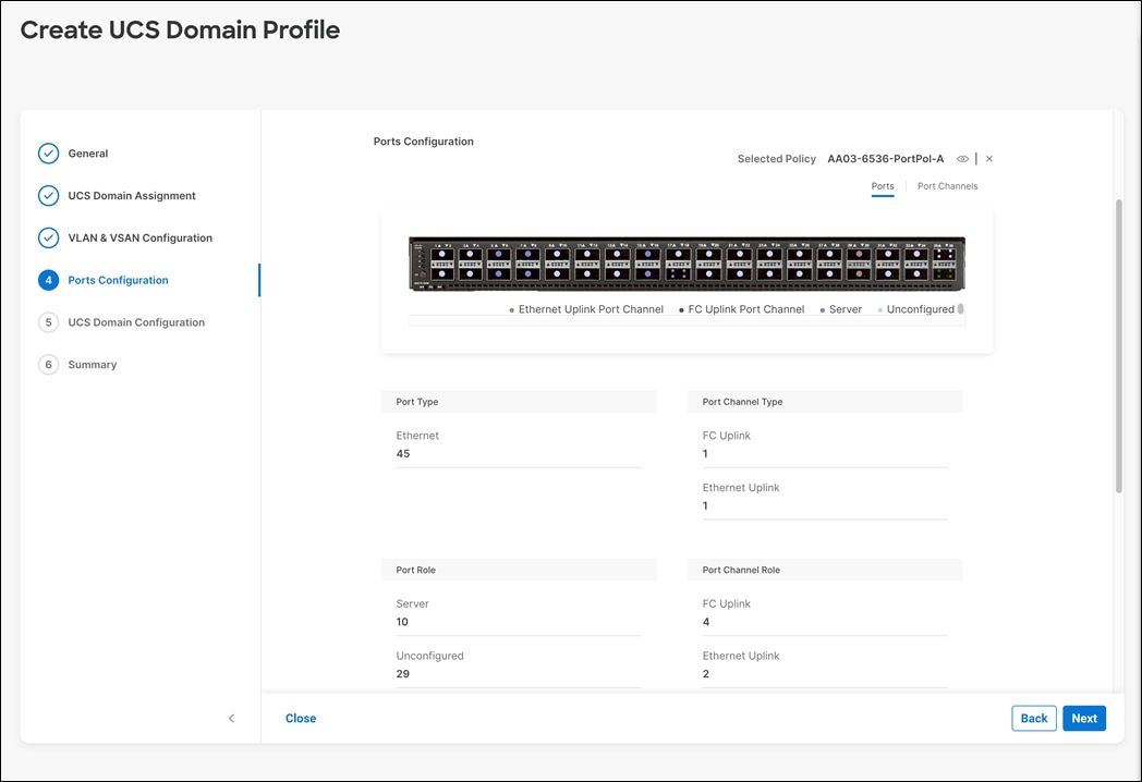
Step 8. Click Next.
Procedure 4. Port Configuration for Fabric Interconnect B
Repeat the steps from section Configure FC Port Channel (FC configuration only) to create the port policy for Fabric Interconnect B including the Ethernet port-channel and the FC port-channel (if configuring SAN). Use the following values for various parameters:
● Name of the port policy: AA03-6536-PortPol-B
● Ethernet port-Channel ID: 12
● FC port-channel ID: 104
● FC VSAN ID: 104
Step 1. Click Select Policy for Fabric Interconnect B.
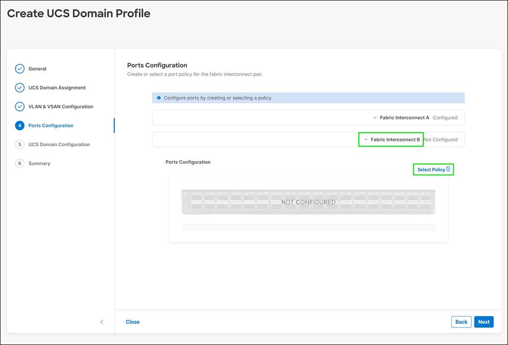
Step 2. In the pane at the right, click Create New.
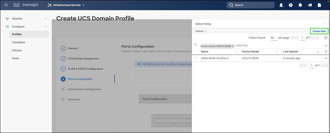
Step 3. Provide a name for the policy (for example, AA03-6536-PortPol-B) and verify the organization selected.
Step 4. Select the UCS-FI-6536 under the Switch Model.
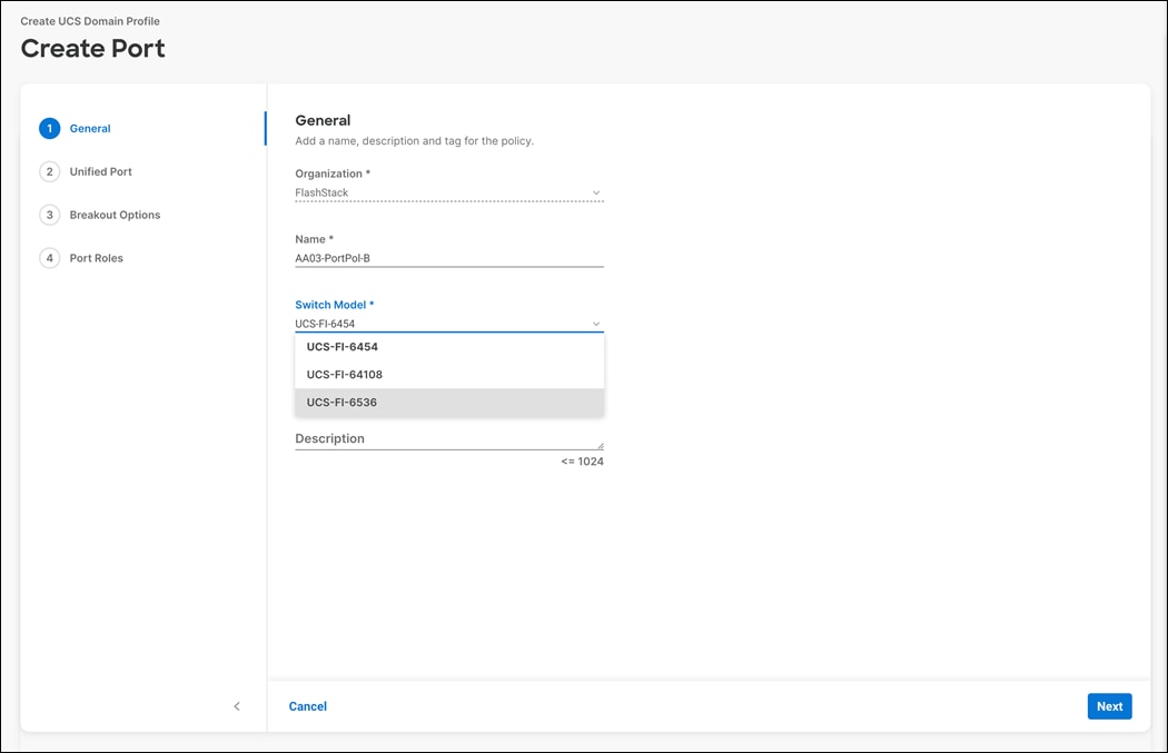
Step 5. Click Next.
Step 6. Repeat the steps you used for Fabric Interconnect A to configure Fibre Channel ports.
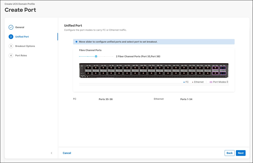
Step 7. Configure server ports.
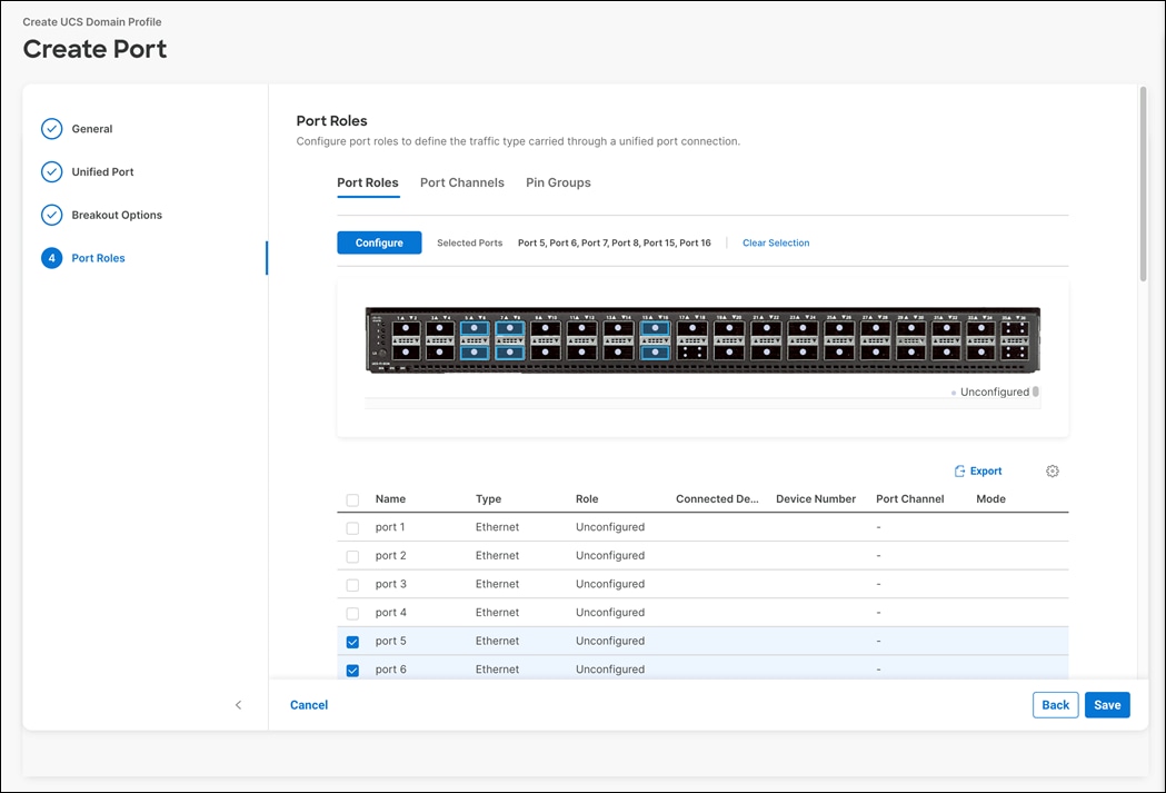
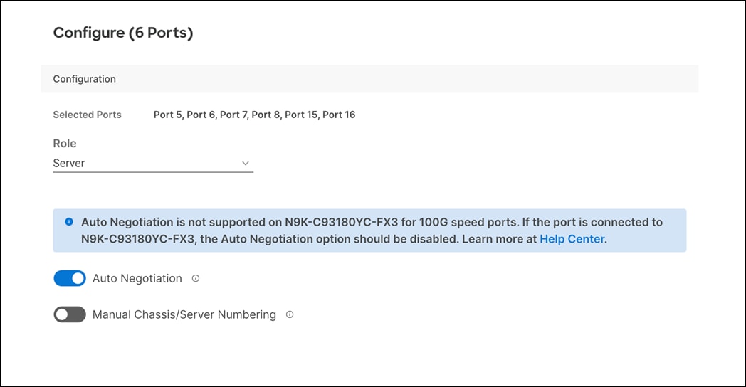
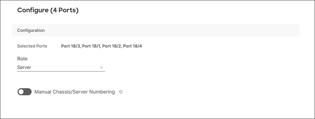
Step 8. Configure Ethernet uplink port channels with appropriate IDs.
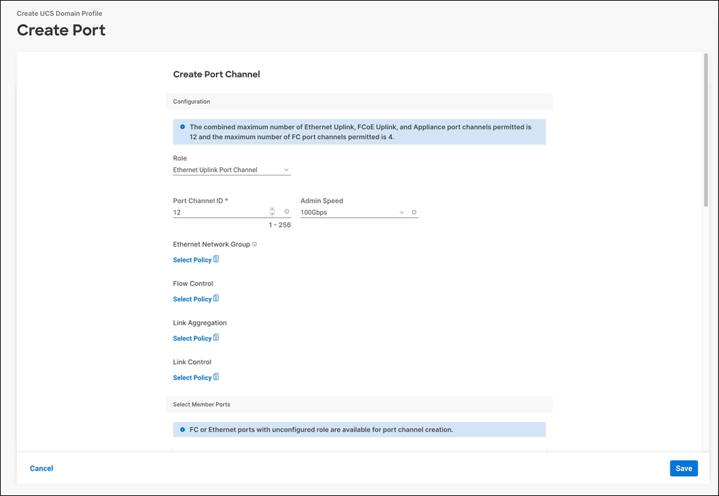
Step 9. Use the previously created Link control policy.
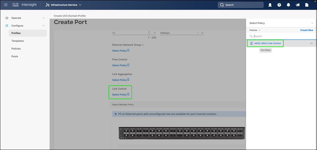
Step 10. Select member ports.
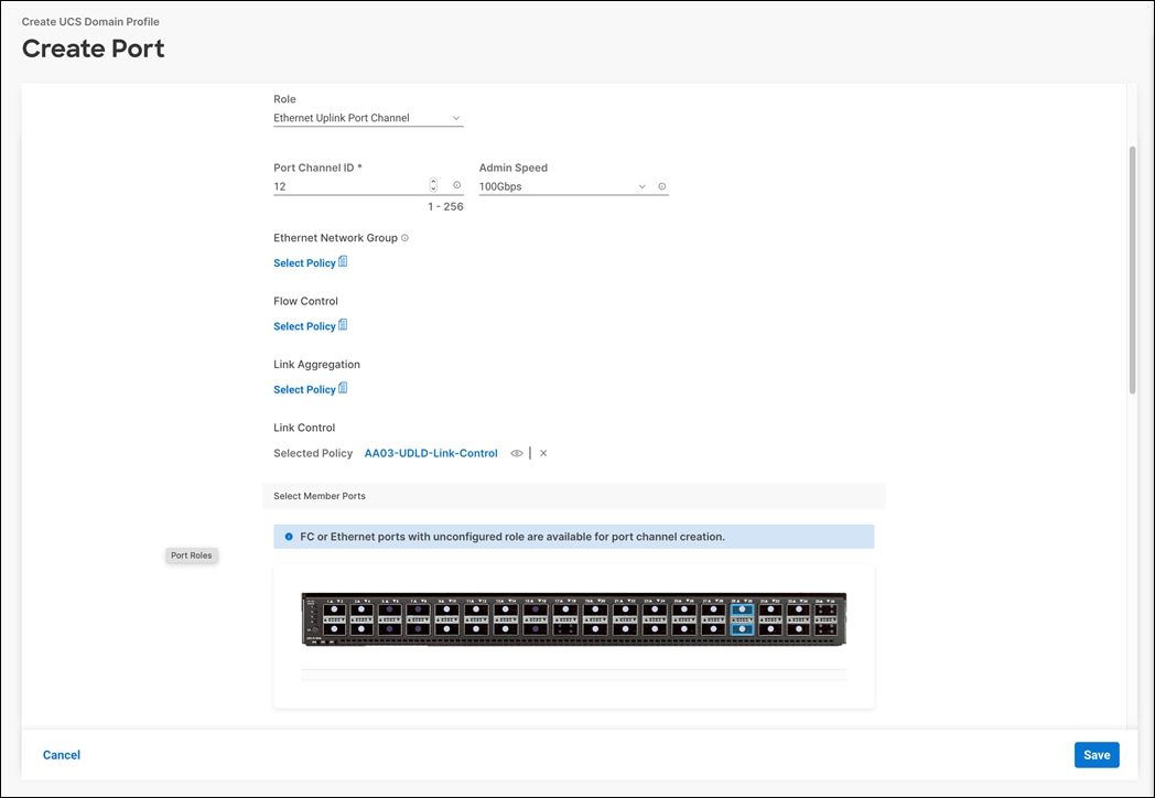
Step 11. Configure Fibre Channel uplink port channels.
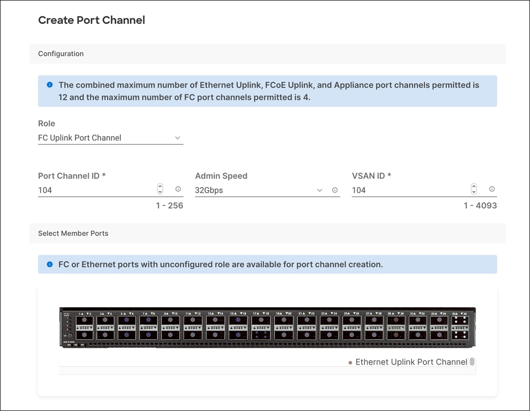
Step 12. Select member ports.
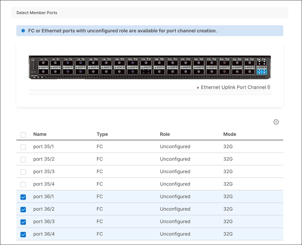
Step 13. Click Save.
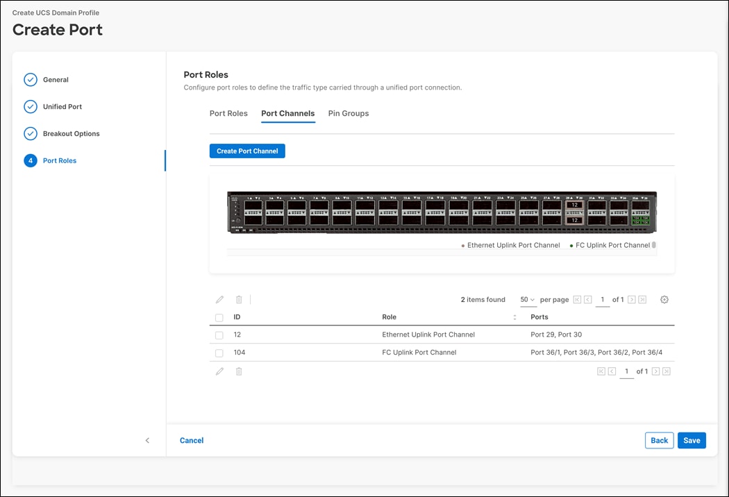
Step 14. Use the summary screen shown here to verify that the ports were selected and configured correctly for Fabric Interconnect B.
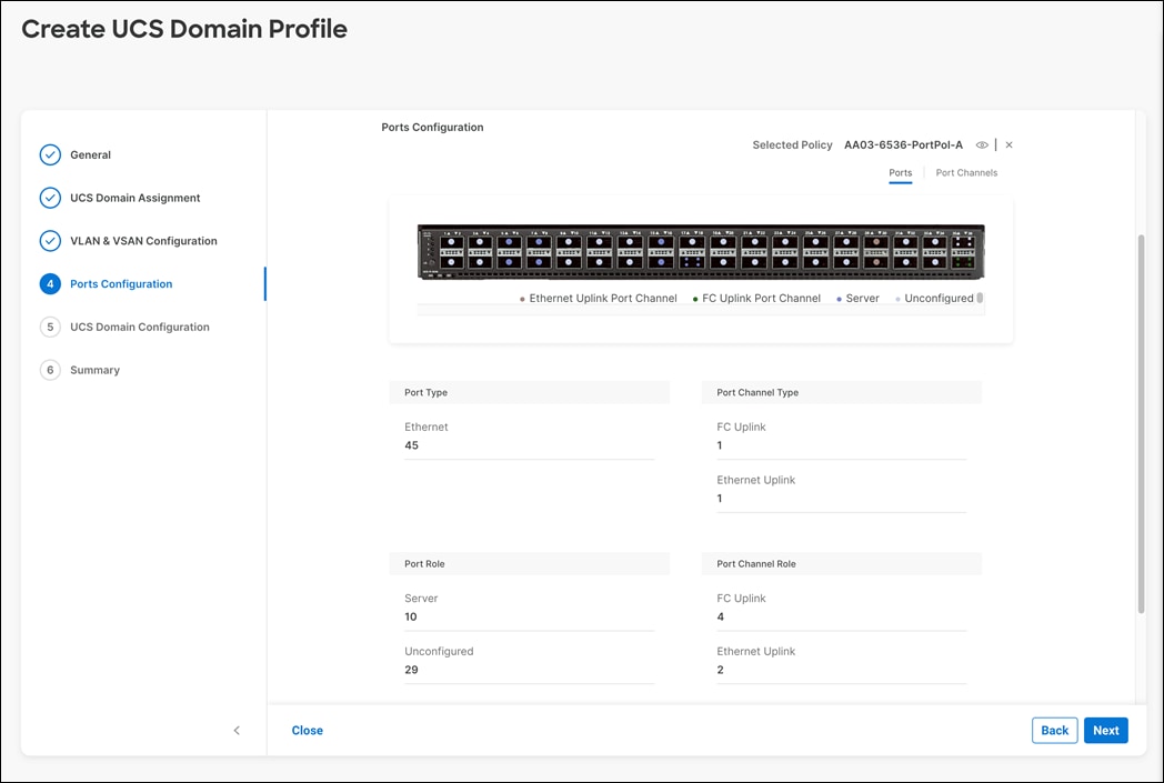
Step 15. When the port configuration for both FIs is complete and looks good, click Next.
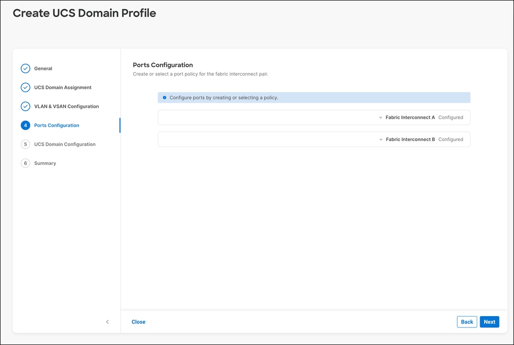
Procedure 5. UCS Domain Configuration
Step 1. Under UCS domain configuration, additional policies can be configured to setup NTP, Syslog, DNS settings, SNMP, QoS and UCS operating mode (end host or switch mode). For this deployment, four policies (NTP, Network Connectivity, SNMP, and System QoS) will be configured, as shown below:
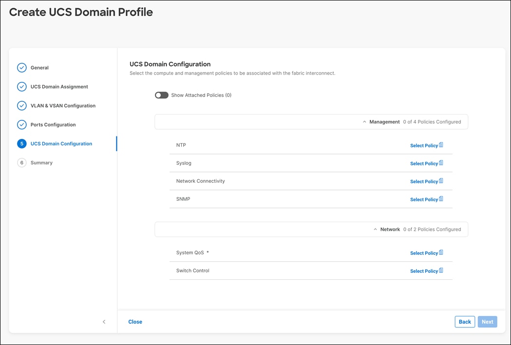
Procedure 6. Configure NTP Policy
Define an NTP server for the UCS Domain and an NTP policy must be configured.
Step 1. Click Select Policy next to NTP and then, in the pane on the right, click Create New
Step 2. Verify correct organization is selected from the drop-down list (for example, FlashStack) and provide a name for the policy (for example, AA03-NTP).
Step 3. Click Next.
Step 4. Enable NTP, provide the first NTP server IP address, and select the time zone from the drop-down list.
Step 5. Add a second NTP server by clicking + next to the first NTP server IP address.
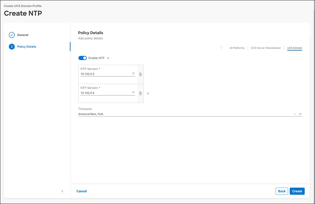
Note: The NTP server IP addresses should be Cisco Nexus switch management IPs. NTP distribution was configured in the Cisco Nexus switches.
Step 6. Click Create.
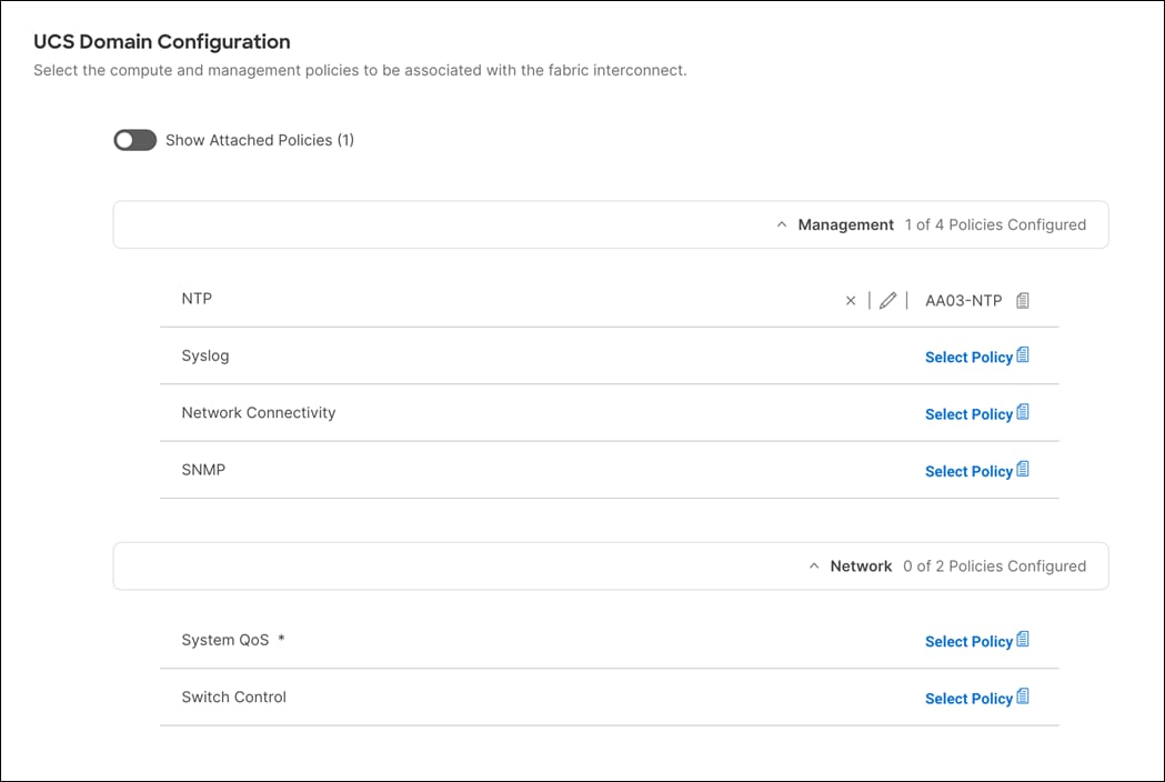
Procedure 7. Configure Network Connectivity Policy
Define the DNS servers for the UCS and a Network Connectivity Policy must be configured.
Step 1. Click Select Policy next to Network Connectivity and then, in the pane on the right, click Create New.
Step 2. Verify correct organization is selected from the drop-down list (for example, FlashStack) and provide a name for the policy (for example, AA03-NetConn).
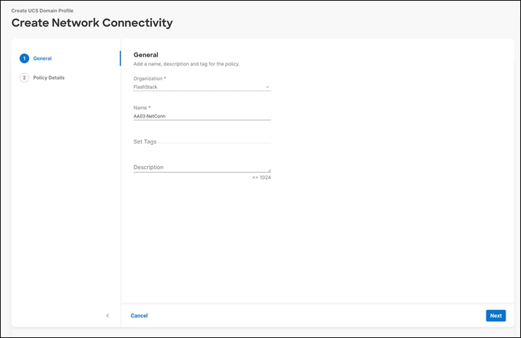
Step 3. Click Next.
Step 4. Provide DNS server IP addresses for Cisco UCS (for example, 10.102.1.151 and 10.102.1.152).
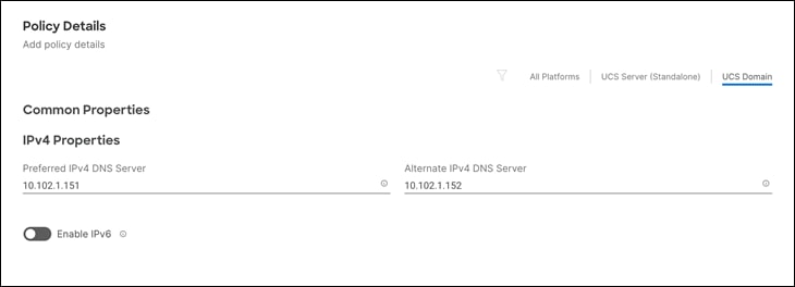
Procedure 8. Configure SNMP Policy
Step 1. Click Select Policy next to SNMP.
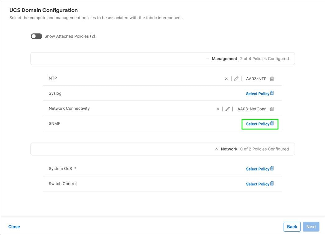
Step 2. In the pane on the right, click Create New.
Step 3. Verify correct organization is selected from the drop-down list (for example, FlashStack) and provide a name for the policy (for example, AA03-SNMP).
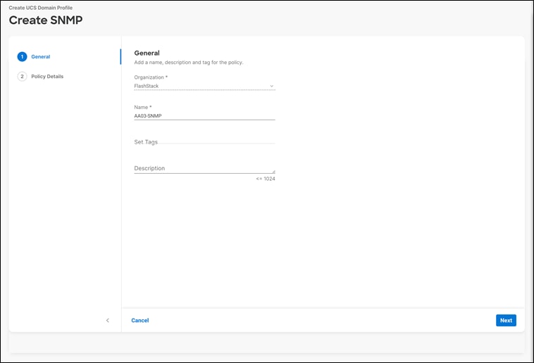
Step 4. Click Next.
Step 5. Provide a System Contact email address, a System Location, and optional Community Strings.
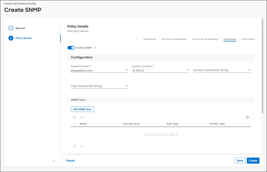
Step 6. Under SNMP Users, click Add SNMP User.
Step 7. This user id will be used for Cisco DCNM SAN to query the UCS Fabric Interconnects. Fill in a user name (for example, snmpadmin), Auth Type SHA, an Auth Password with confirmation, Privacy Type AES, and a Privacy Password with confirmation. Click Add.
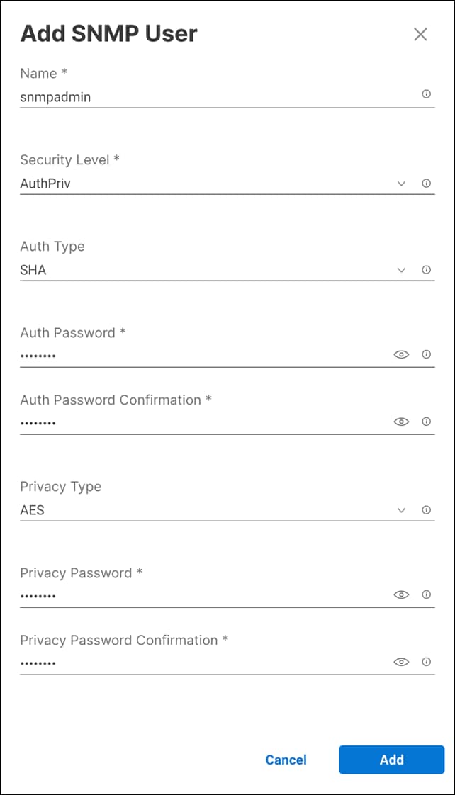
Step 8. Optionally, add an SNMP Trap Destination (for example, the DCNM SAN IP Address). If the SNMP Trap Destination is V2, you must add Trap Community String.
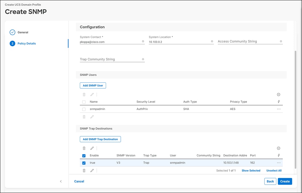
Step 9. Click Create.
Procedure 9. Configure System QoS Policy
Define the QoS settings for Cisco UCS and the QoS System QoS Policy must be configured.
Step 1. Click Select Policy next to System QoS.

Step 2. In the pane on the right, click Create New.
Step 3. Verify correct organization is selected from the drop-down list (for example, FlashStack) and provide a name for the policy (for example, AA03-QoS).
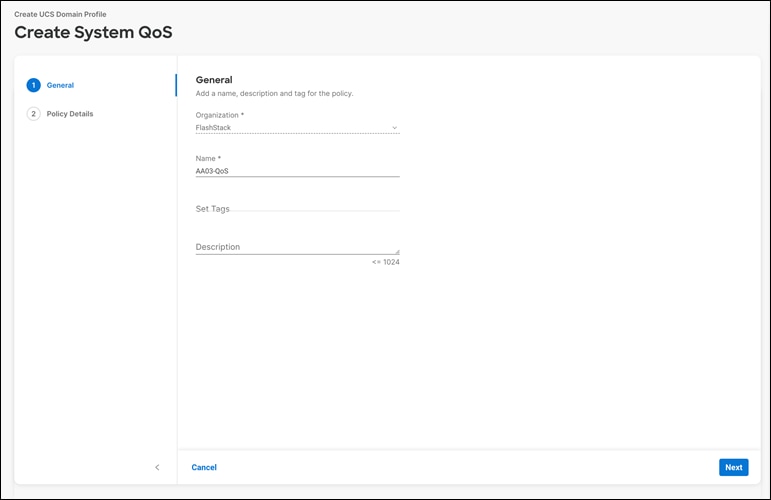
Step 4. Click Next.
Step 5. Change the MTU for Best Effort class to 9216.
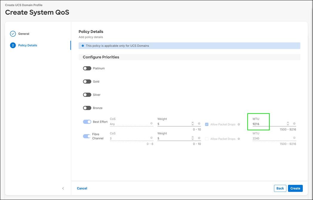
Step 6. Keep the default selections or change the parameters if necessary.
Step 7. Click Create.
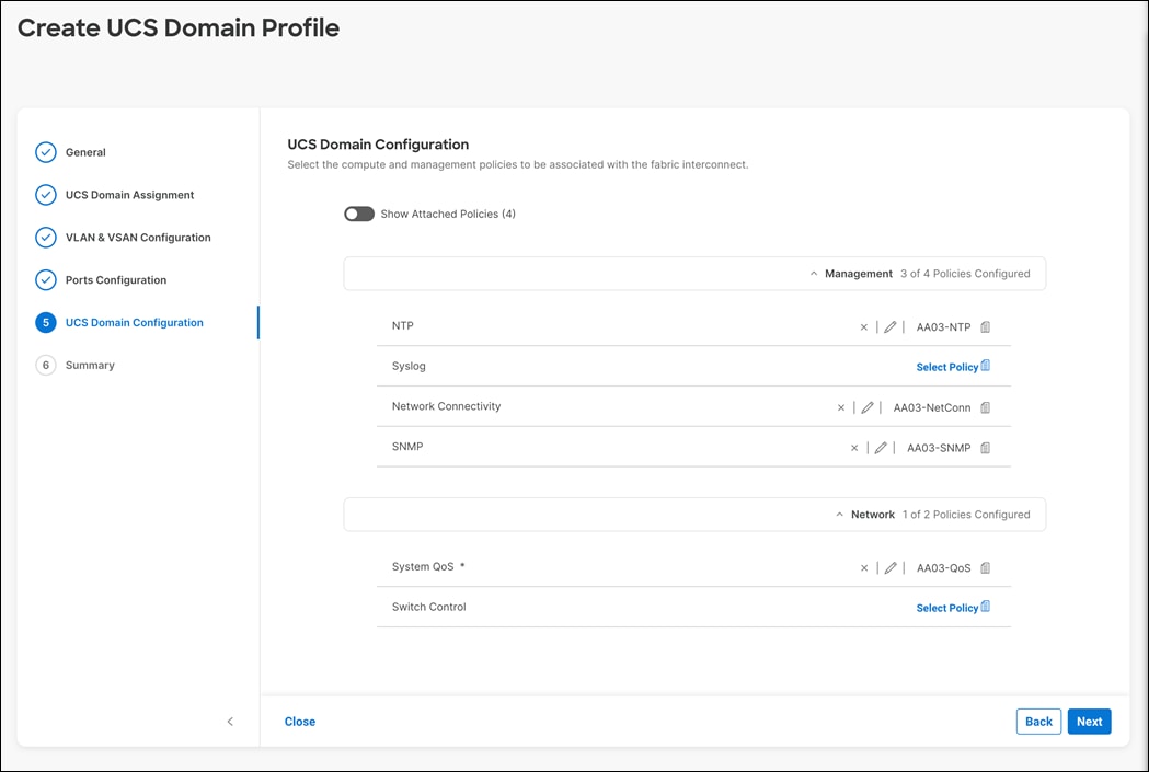
Step 8. Click Next.
Procedure 10. Verify Settings and Configuration
Step 1. To verify all the settings (including expanding the Fabric Interconnect settings) and make sure the configuration is correct.
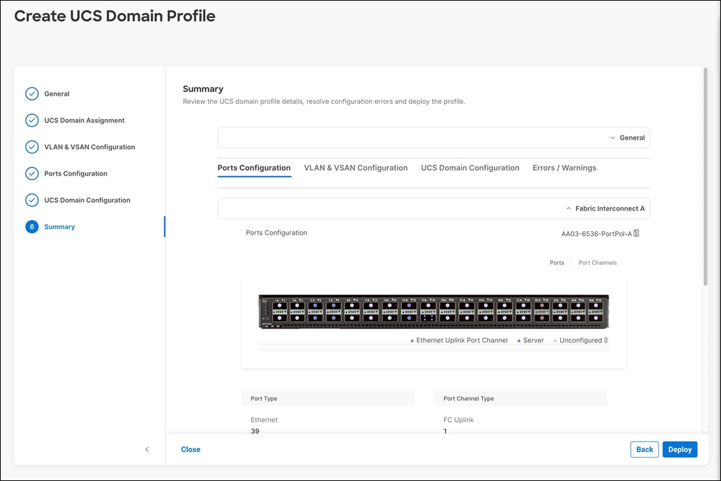
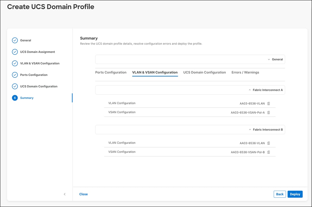
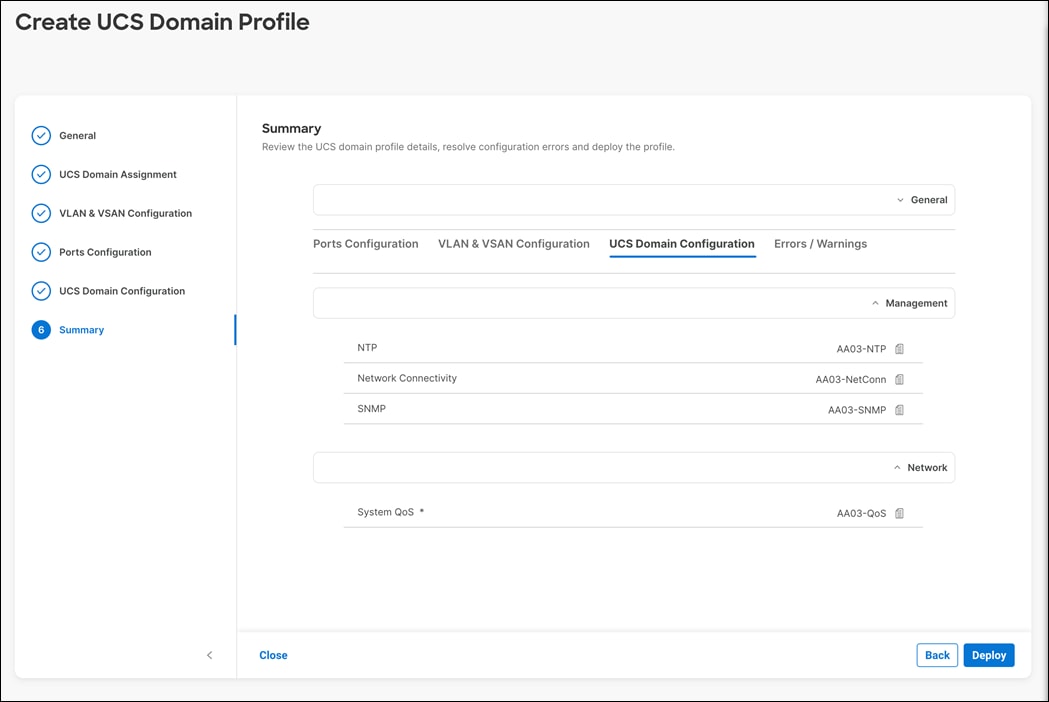
Procedure 11. Deploy the Cisco UCS Domain Profile
After verifying the domain profile configuration, deploy the Cisco UCS profile.
Step 1. From the UCS domain profile Summary view, click Deploy.
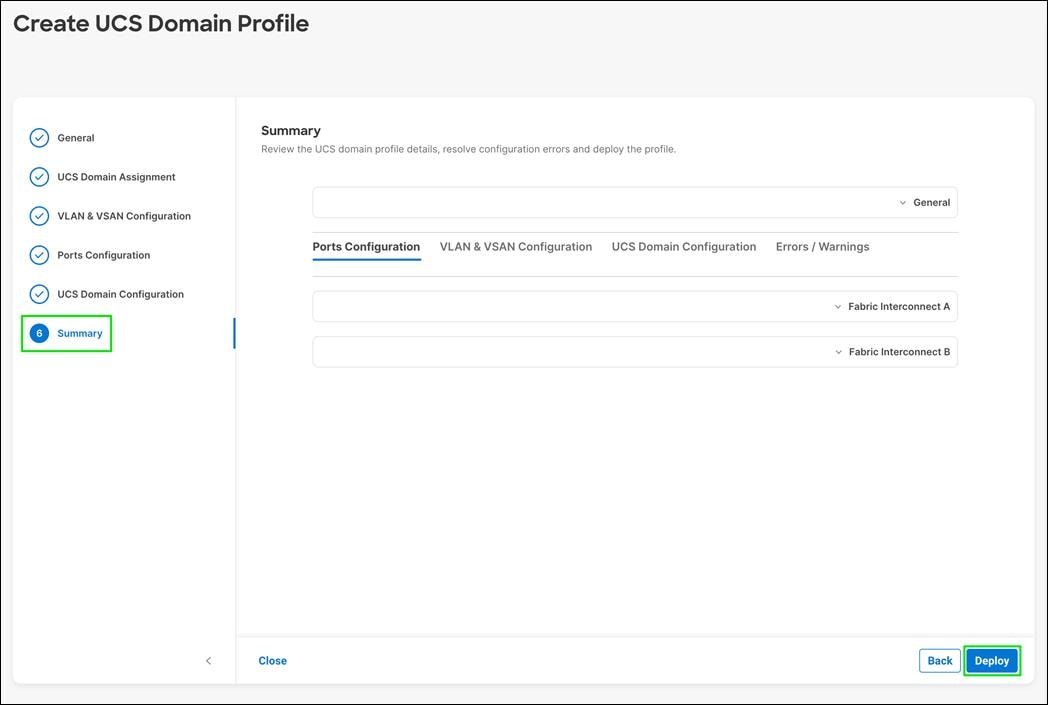
Step 2. Acknowledge any warnings and click Deploy again.
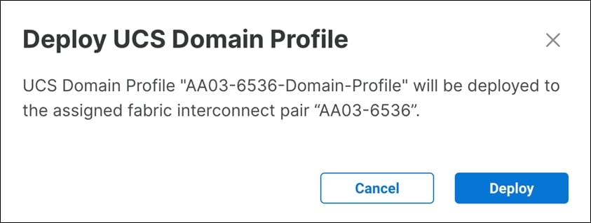
Step 3. The system will take some time to validate and configure the settings on the fabric interconnects. Log into the console servers to see when the Cisco UCS fabric interconnects have finished configuration and are successfully rebooted.
Procedure 12. Verify Cisco UCS Domain Profile Deployment
When the Cisco UCS domain profile has been successfully deployed, the Cisco UCS chassis and the blades should be successfully discovered.
Note: It takes a while to discover the blades for the first time. Keep an eye on the number of outstanding tasks in Cisco Intersight:

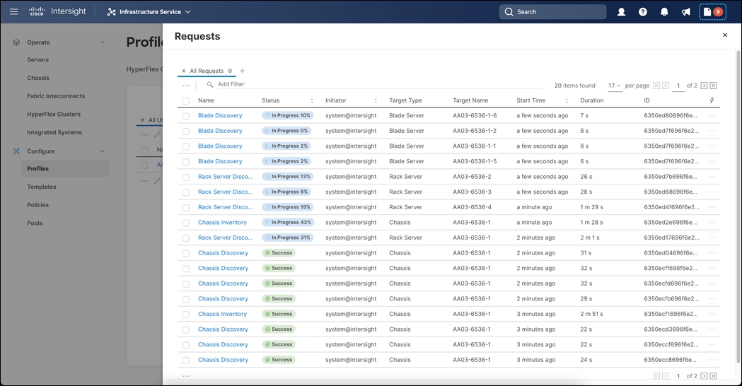
Step 1. Under Infrastructure Service > Configure > Profiles > UCS Domain Profiles, verify that the domain profile progresses and has successfully deployed after few minutes.
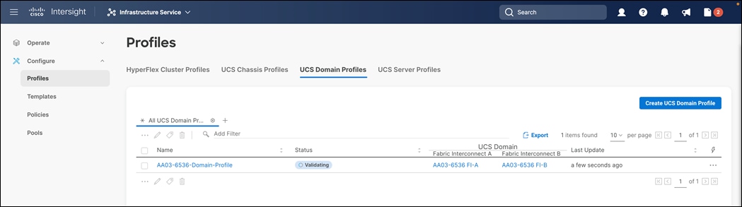
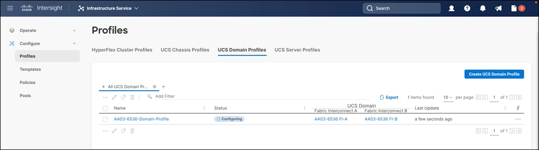
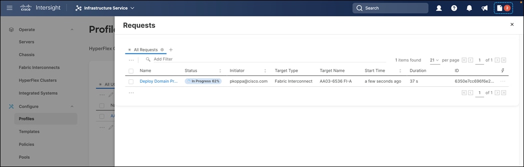
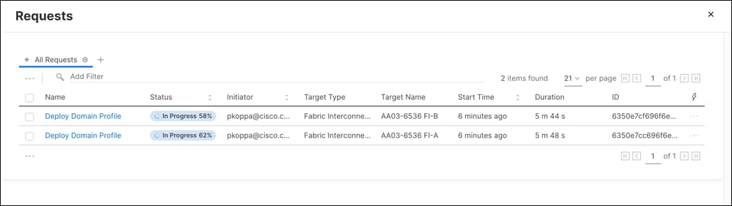
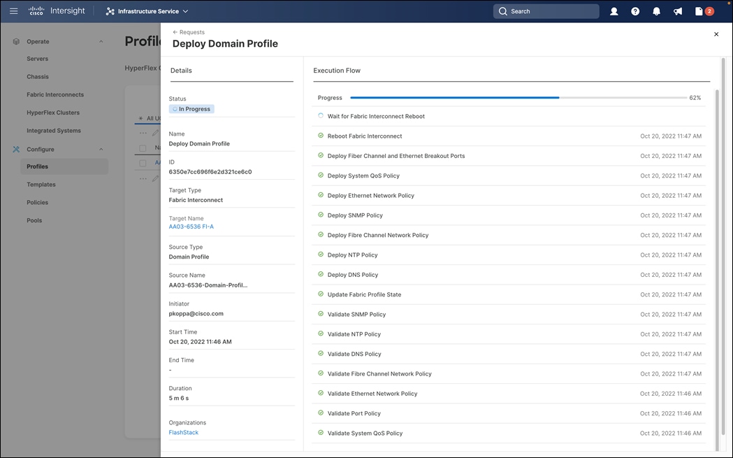
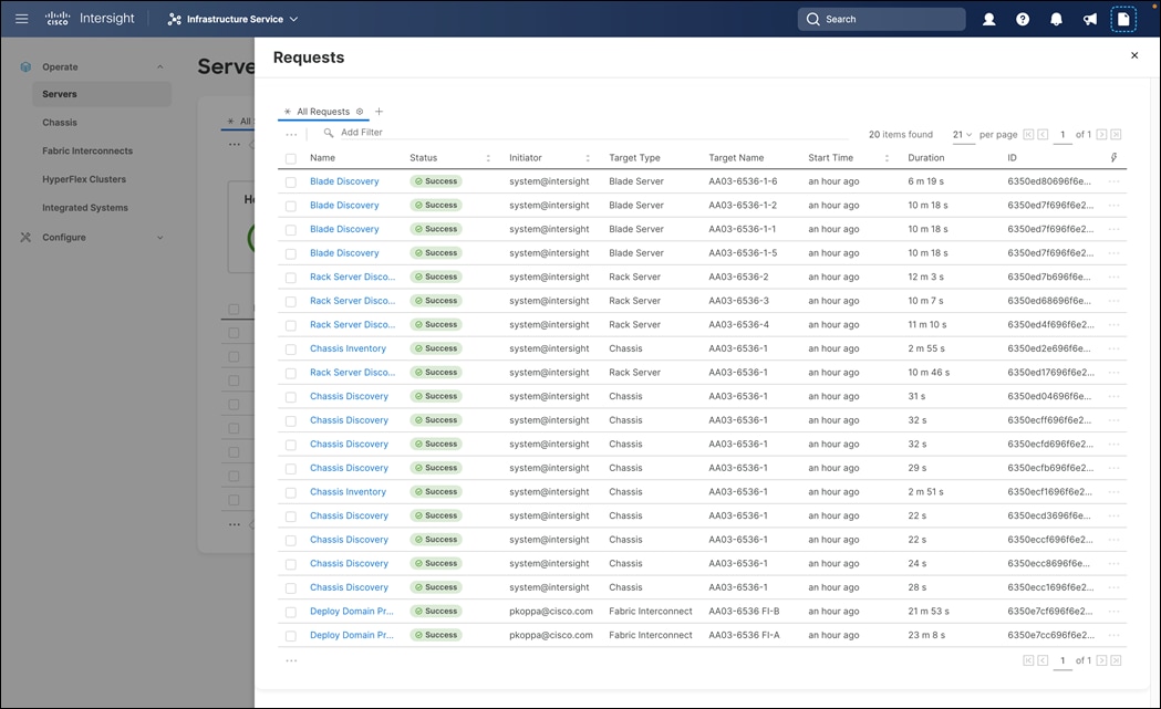
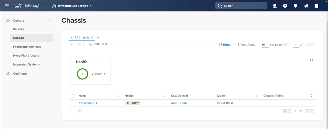
Step 2. Verify that both Fabric interconnects are visible under: Infrastructure Service > Operate > Fabric Interconnects.
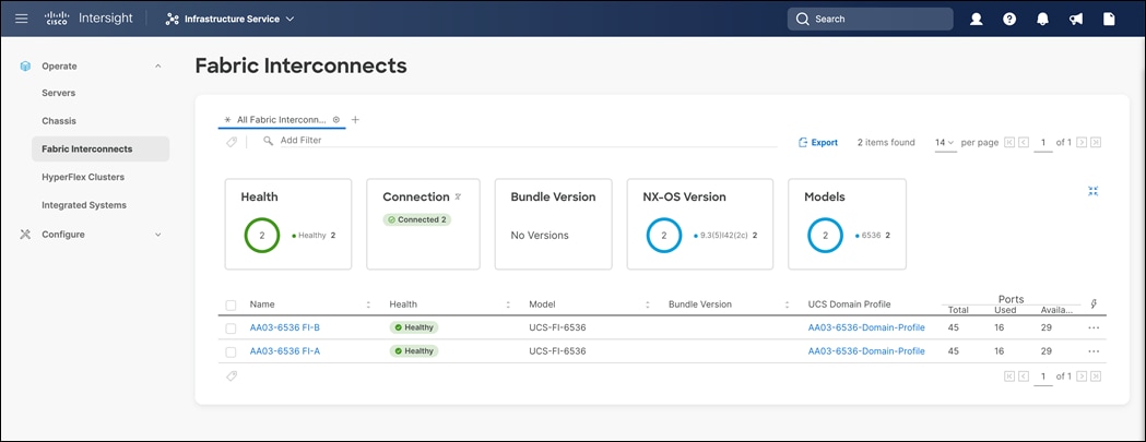
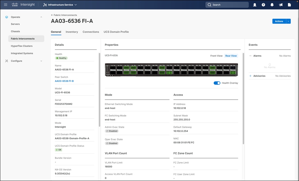
Step 3. Verify that the chassis have been successfully discovered and are visible under: Infrastructure Service > Operate > Chassis.
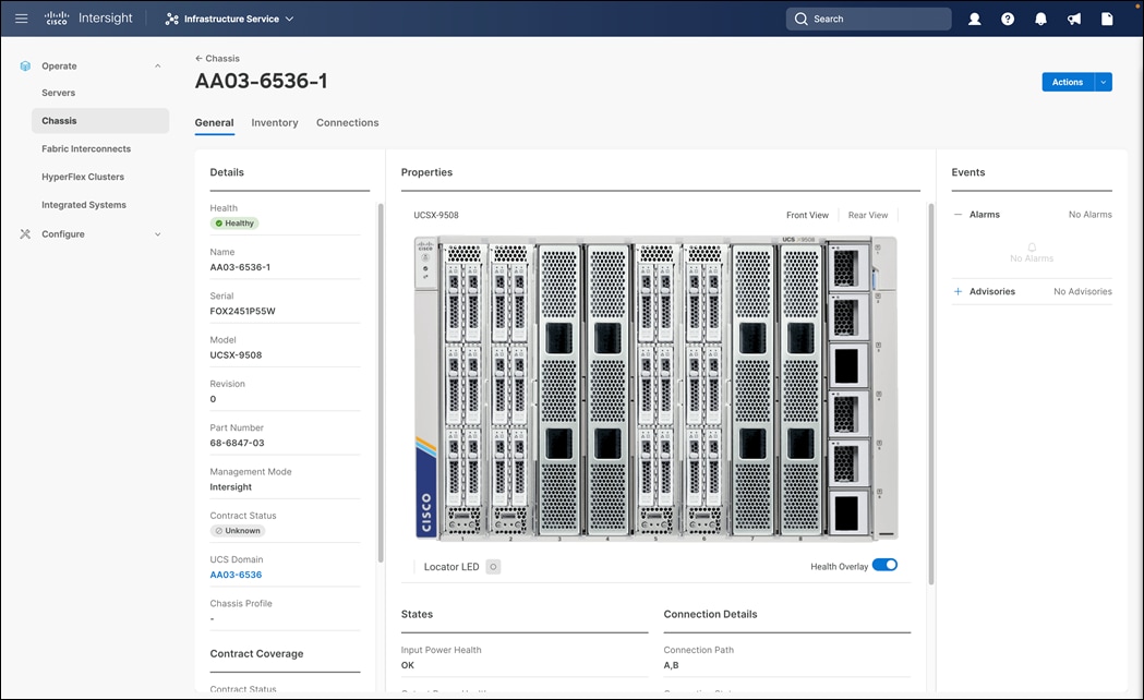
Step 4. Make sure all the servers of the chassis are visible under: Infrastructure Service > Operate > Servers.
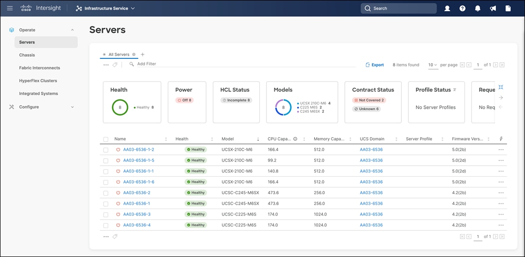
Configure Cisco UCS Chassis Profile
Cisco UCS Chassis profile in Cisco Intersight allow customers to configure various parameters for chassis, including:
● IMC Access Policy: IP configuration for the in-band chassis connectivity. This setting is independent of Server IP connectivity and only applies to communication to and from chassis.
● SNMP Policy, and SNMP trap settings.
● Power Policy to enable power management and power supply redundancy mode.
● Thermal Policy to control the speed of FANs (only applicable to Cisco UCS 5108)
A chassis policy can be assigned to any number of chassis profiles to provide a configuration baseline for a chassis. In this deployment, no chassis profile was created or attached to the chassis, but customers can configure policies to configure SNMP or Power parameters and attach them to the chassis.
Configure Server Profile Template
In the Cisco Intersight platform, a server profile enables resource management by simplifying policy alignment and server configuration. The server profiles are derived from a server profile template. The server profile template and its associated policies can be created using the server profile template wizard. After creating a server profile template, customers can derive multiple consistent server profiles from the template.
The server profile templates captured in this deployment guide supports Cisco UCS X210c M6 and B200M6 compute nodes with 5th Generation and 4th Generation VICs, and Cisco UCS C245 and C225 compute nodes with 4th Generation VICs.
vNIC and vHBA Placement for Server Profile Template
In this deployment guide, separate templates are created that can be attached to individual servers for iSCSI connected storage and for Fibre Channel connected storage. The vNIC and vHBA layout is covered below. While most of the policies are common across various templates, the LAN connectivity and SAN connectivity policies are unique to each of the templates.
The vNIC and vHBA layout is explained below for both FC and iSCSI connected storage.
The iSCSI boot from SAN hosts uses 6 vNICs configured as list in Table 13:
Table 13. vNIC Placement for iSCSI Connected Storage
| vNIC/vHBA Name |
Slot ID |
Switch ID |
PCI Order |
| 00-vSwitch0-A |
MLOM |
A |
0 |
| 01-vSwitch0-B |
MLOM |
B |
1 |
| 02-VDS0-A |
MLOM |
A |
2 |
| 03-VDS0-B |
MLOM |
B |
3 |
| 04-iSCSI-A |
MLOM |
A |
4 |
| 05-iSCSI-B |
MLOM |
B |
5 |
Four vNICs and four vHBAs are configured to support FC boot from SAN. Two vHBAs (vHBA-A and vHBA-B) are used for boot from SAN connectivity and the remaining two vHBAs are used to support FC-NVMe. These devices are manually placed as listed in Table 14:
Table 14. vHBA and vNIC Placement for FC with FC-NVMe Connected Storage
| vNIC/vHBA Name |
Slot |
Switch ID |
PCI Order |
| 00-vSwitch0-A |
MLOM |
A |
0 |
| 01-vSwitch0-B |
MLOM |
B |
1 |
| 02-VDS0-A |
MLOM |
A |
2 |
| 03-VDS0-B |
MLOM |
B |
3 |
| vHBA-A |
MLOM |
A |
4 |
| vHBA-B |
MLOM |
B |
5 |
| vHBA-NVMe-A |
MLOM |
A |
6 |
| vHBA-NVMe-B |
MLOM |
B |
7 |
Note: If FC-NVMe connectivity is not required, please use the following vNIC and vHBA layout.
Four vNICs and two vHBAs are configured to support FC boot from SAN. These devices are manually placed as listed in Table 15:
Table 15. vHBA and vNIC Placement for FC Connected Storage
| vNIC/vHBA Name |
Slot |
Switch ID |
PCI Order |
| 00-vSwitch0-A |
MLOM |
A |
0 |
| 01-vSwitch0-B |
MLOM |
B |
1 |
| 02-VDS0-A |
MLOM |
A |
2 |
| 03-VDS0-B |
MLOM |
B |
3 |
| vHBA-A |
MLOM |
A |
4 |
| vHBA-B |
MLOM |
B |
5 |
Procedure 1. Server Profile Template Creation
Step 1. Open a browser to Cisco Intersight, https://intersight.com.
Step 2. Log into Cisco Intersight portal.
Step 3. From Service Selector, select Infrastructure Service.
Step 4. From the left navigation pane, click Configure > Templates.
Step 5. Click Create UCS Server Profile Template.
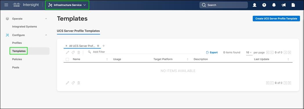
Procedure 2. General
Step 1. Select the organization from the drop-down list (for example, FlashStack).
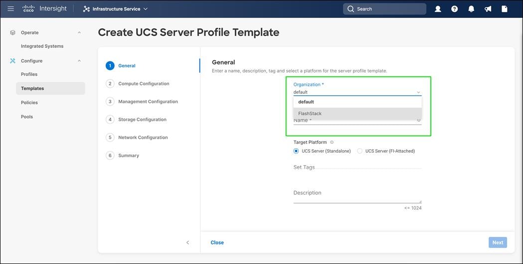
Step 2. Provide a name for the server profile template. For example:
● AA03-iSCSI-Boot-Template (iSCSI boot from SAN for X210C compute nodes)
● AA03-FC-Boot-Template (FC Boot from SAN for X210C compute nodes)
● AA03-AMD-iSCSI-Boot-Template (iSCSI boot from SAN for AMD CPU-based UCS C225 and C245 M6 servers)
● AA03-AMD-FC-Boot-Template (FC Boot from SAN for AMD CPU-based UCS C225 and C245 M6 servers)
● FC-Boot-NVME-Template (FC boot from SAN with support for NVMe-FC).
Step 3. It is required to create separate server profile templates since the policies mapped to those server profiles will vary based on CPU type, Server , VIC Generations, Boot type etc.
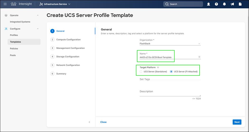
Step 4. Select UCS Server (FI-Attached) as the Target Platform.
Step 5. Click Next.
Procedure 3. Compute Configuration - Configure UUID Pool
Step 1. Click Select Pool under UUID Pool.
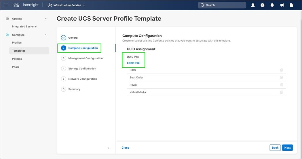
Step 2. In the pane on the right, click Create New.
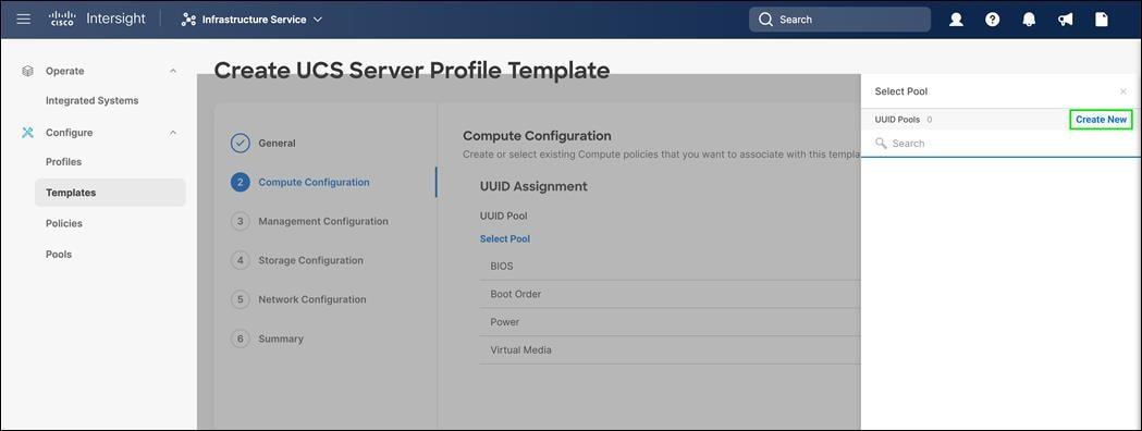
Step 3. Verify the correct organization is selected from the drop-down list (for example, FlashStack) and provide a name for the UUID Pool.
Step 4. Provide a name for the pool (for example, AA03-UUID-Pool).
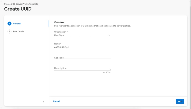
Step 5. Click Next
Step 6. Provide a UUID Prefix (for example, a random prefix of 33FB3F9C-BF35-AA03 was used).
Step 7. Add a UUID block.
Step 8. Click Create.
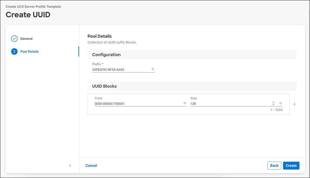
BIOS Policy
BIOS policy varies between Cisco UCS X-Series, Cisco UCS M5 servers, AMD CPU-based Cisco UCS C225 M6 and Cisco UCS C245 M6 Rack servers due to various performance tuning that can be implemented.
Procedure 1. Configure BIOS Policy for Cisco UCS X-Series
Step 1. Click Select Policy next to BIOS.

Step 2. In the pane on the right, click Create New.

Step 3. Verify the correct organization is selected from the drop-down list (for example, FlashStack) and provide a name for the policy (for example, AA03-Intel-M6-Virt-BIOS).

Step 4. Click Next.
Step 5. On the Policy Details screen, select appropriate values for the BIOS settings. In this deployment, the BIOS values were selected based on recommendations in the performance tuning guide for Cisco UCS M6 BIOS: https://www.cisco.com/c/en/us/products/collateral/servers-unified-computing/ucs-b-series-blade-servers/performance-tuning-guide-ucs-m6-servers.html.
Step 6. Set the parameters below and leave all other parameters set to platform-default:

● LOM and PCIe Slot -> CDN Support for LOM: Enabled
● Power and Performance -> Enhanced CPU performance: Auto
● Processor:
◦ Processor C1E: Enabled
◦ Processor C6 Report: Enabled
◦ Energy Efficient Turbo: Enabled
● Memory -> NVM Performance Setting: Balanced Profile
● Server Management -> Consistent Device Naming: enabled
Step 7. Click Create.
Procedure 2. Configure BIOS Policy for Cisco UCS M5 Servers
Note: Create these policies only if you have Cisco UCS M5 family servers in your environment.
Step 1. Click Select Policy next to BIOS.
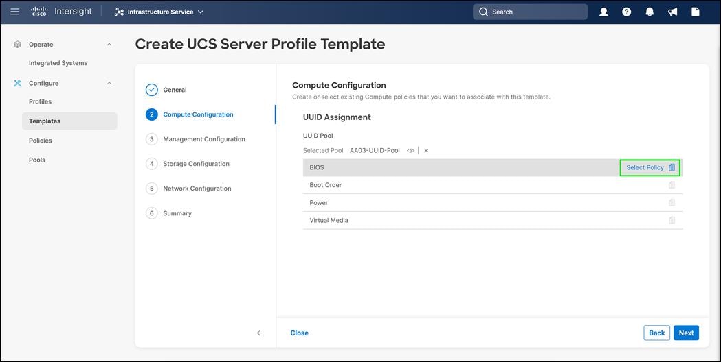
Step 2. In the pane on the right, click Create New.
Step 3. Verify the correct organization is selected from the drop-down list (for example, FlashStack) and provide a name for the policy (for example, AA03-Intel-M5-Virt-BIOS).

Step 4. Click Next.
Step 5. On the Policy Details screen, select appropriate values for the BIOS settings. In this deployment, the BIOS values were selected based on recommendations in the performance tuning guide for Cisco UCS M5 BIOS: https://www.cisco.com/c/en/us/products/collateral/servers-unified-computing/ucs-b-series-blade-servers/white-paper-c11-744678.html
Step 6. Set the parameters below and leave all other parameters set to platform-default:
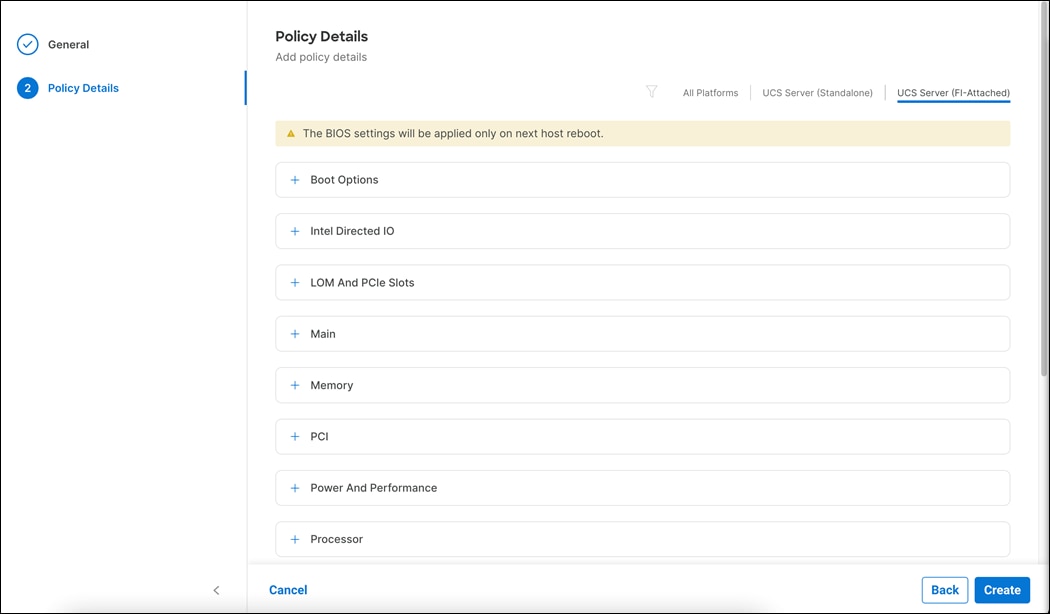
● Memory > NVM Performance Setting: Balanced Profile
● Processor:
◦ Power Technology: custom
◦ Processor C1E: disabled
◦ Processor C3 Report: disabled
◦ Processor C6 Report: disabled
◦ CPU C State: disabled
● Server Management > Consistent Device Naming: enabled
Step 7. Click Create.
Procedure 3. Configure BIOS Policy for AMD CPU-based Cisco UCS C225 M6 and Cisco UCS C245 M6 Rack Servers
Step 1. Click Select Policy next to BIOS.
Step 2. In the pane on the right, click Create New.

Step 3. Verify the correct organization is selected from the drop-down list (for example, FlashStack) and provide a name for the policy (for example, AA03-AMD-M6-Virt-BIOS).

Step 4. Click Next.
Step 5. On the Policy Details screen, select appropriate values for the BIOS settings. In this deployment, the BIOS values were selected based on recommendations in the performance tuning guide for Cisco UCS C225 M6 and C245 M6 Rack Servers with 3rd Gen AMD EPYC Processors BIOS: https://www.cisco.com/c/en/us/products/collateral/servers-unified-computing/ucs-c-series-rack-servers/performance-tuning-wp.html
Step 6. Set the parameters below and leave all other parameters set to platform-default:

● Memory > NUMA Nodes per Socket: NPS4
● Processor:
◦ APBDIS: 1
◦ Fixed SOC P-State: P0
◦ ACPI SRAT L3 Cache As NUMA Domain: enabled
● Server Management > Consistent Device Naming: enabled
Step 7. Click Create.
Procedure 4. Configure Boot Order Policy for iSCSI Hosts
Note: The iSCSI SAN boot order policy is different from Fibre Channel SAN boot policy. Configure accordingly.
Step 1. Click Select Policy next to Boot Order.
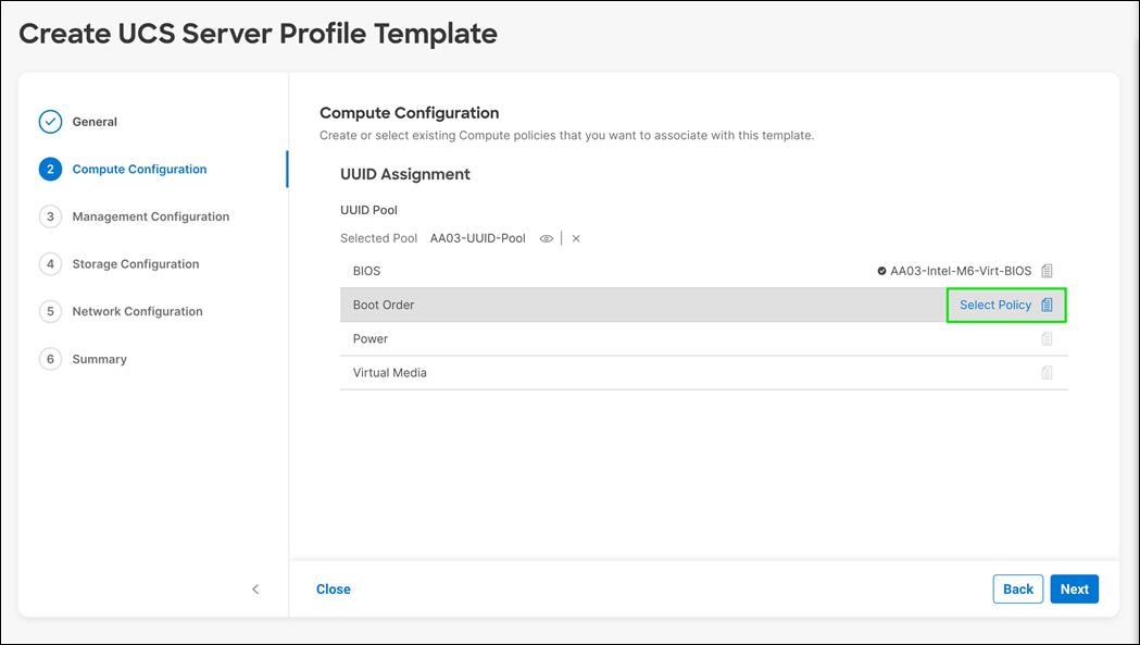
Step 2. In the pane on the right, click Create New
Step 3. Verify the correct organization is selected from the drop-down list (for example, FlashStack) and provide a name for the policy (for example, AA03-iSCSI-BootOrder-Policy).
Step 4. Click Next.
Step 5. From Configure Boot Mode, select Unified Extensible Firmware Interface (UEFI).
Step 6. Click Enable Secure Boot.
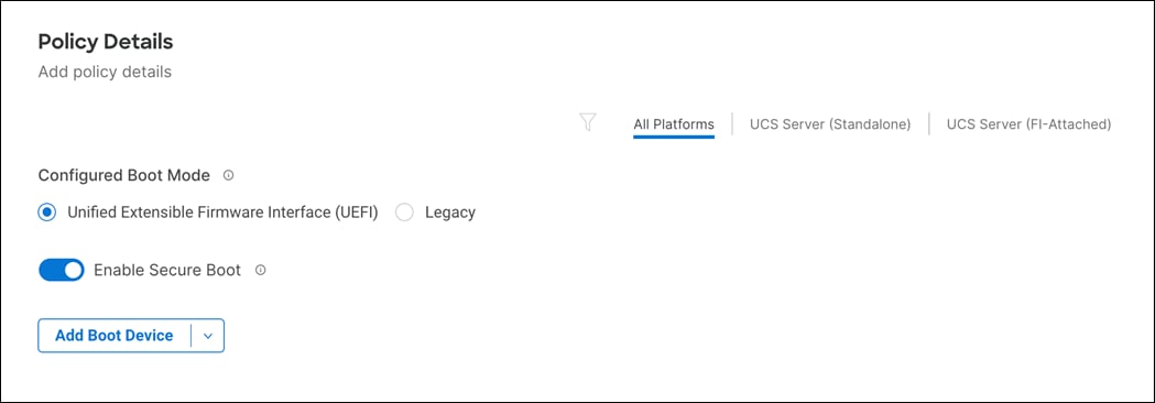
Step 7. Click Add Boot Device drop-down list and select Virtual Media.

Step 8. Provide a device name (for example, KVM-Mapped-ISO) and then, for the subtype, select KVM Mapped DVD.
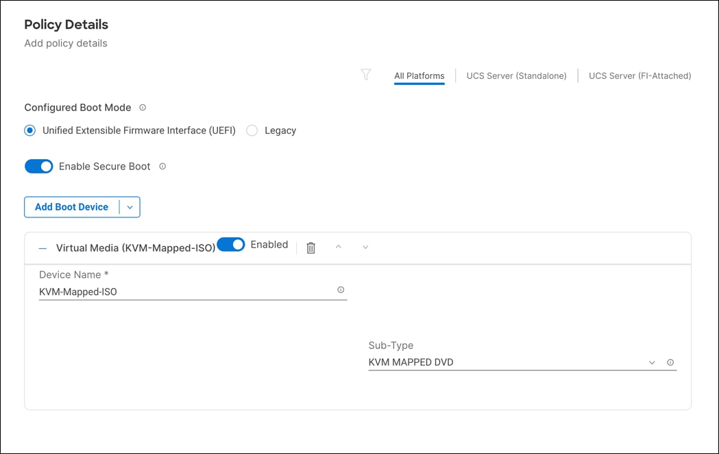
Step 9. From the Add Boot Device drop-down list, select iSCSI Boot.
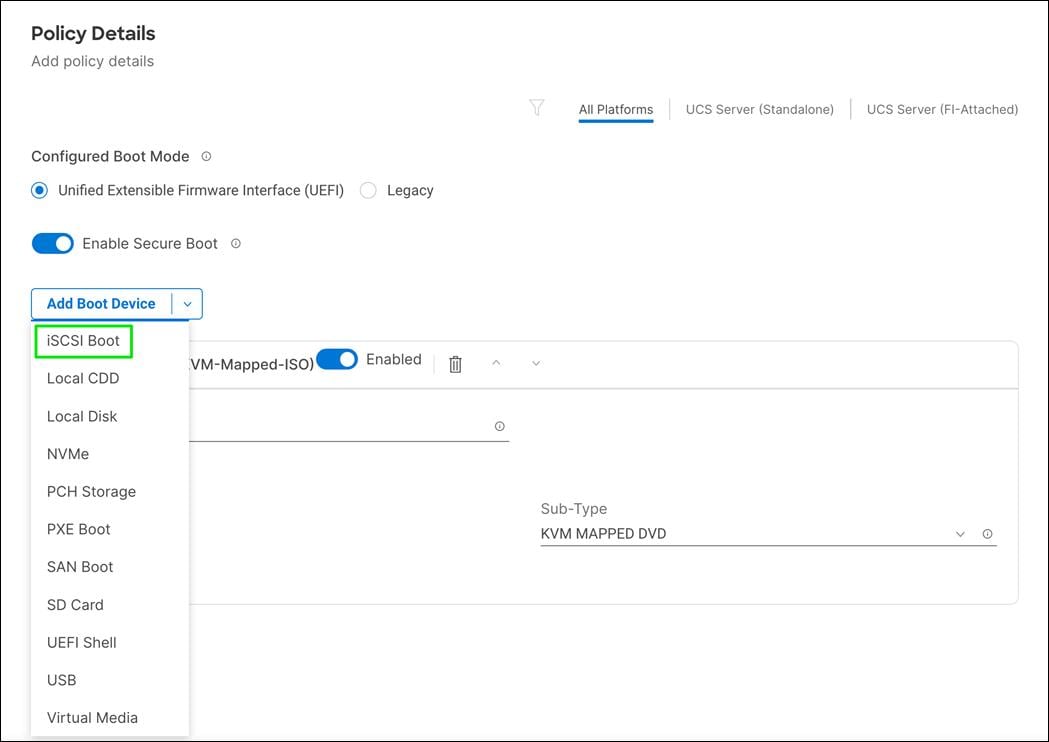
Step 10. Provide the Device Name: ISCSI-A-Boot and the exact name of the interface used for iSCSI boot under Interface Name: 04-iSCSI-A
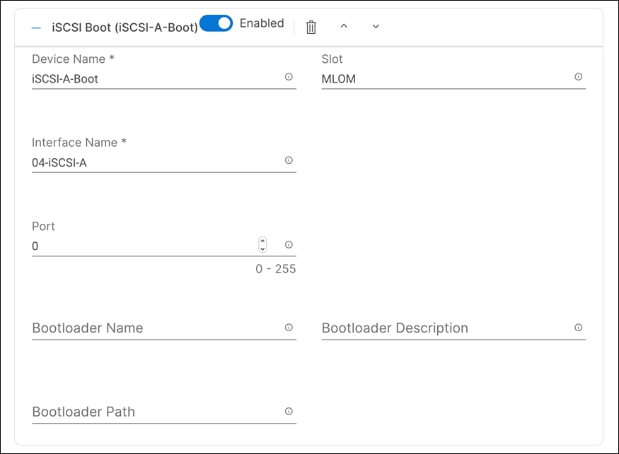
Step 11. From the Add Boot Device drop-down list, select iSCSI Boot.
Step 12. Provide the Device Name: ISCSI-B-Boot and the exact name of the interface used for iSCSI boot under Interface Name: 05-iSCSI-B.
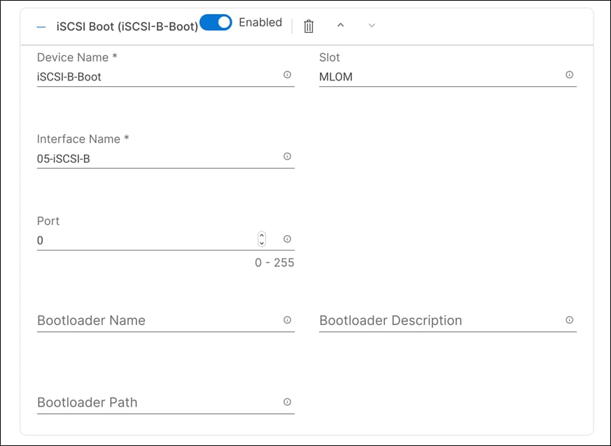
Step 13. Verify the order of the boot policies and adjust the boot order as necessary using arrows next to the Delete button.
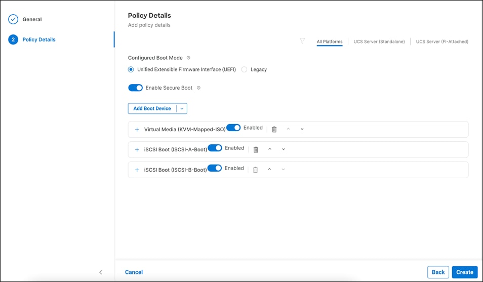
Step 14. Click Create.
Procedure 5. Configure Boot Order Policy for FC Hosts
Step 1. Click Select Policy next to Boot Order.

Step 2. In the pane on the right, click Create New.
Step 3. Verify the correct organization is selected from the drop-down list (for example, FlashStack) and provide a name for the policy (for example, AA03-FC-BootOrder-Policy).

Step 4. Click Next.
Step 5. For Configured Boot Mode, select Unified Extensible Firmware Interface (UEFI).
Step 6. Turn on Enable Secure Boot.
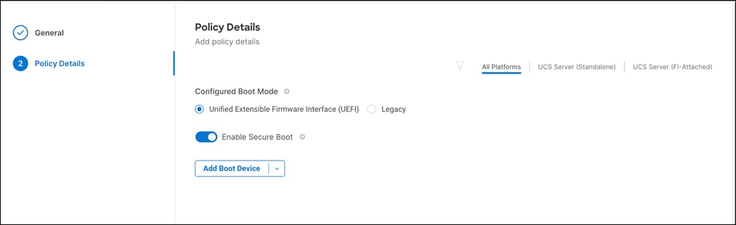
Step 7. Click Add Boot Device drop-down list and select Virtual Media.
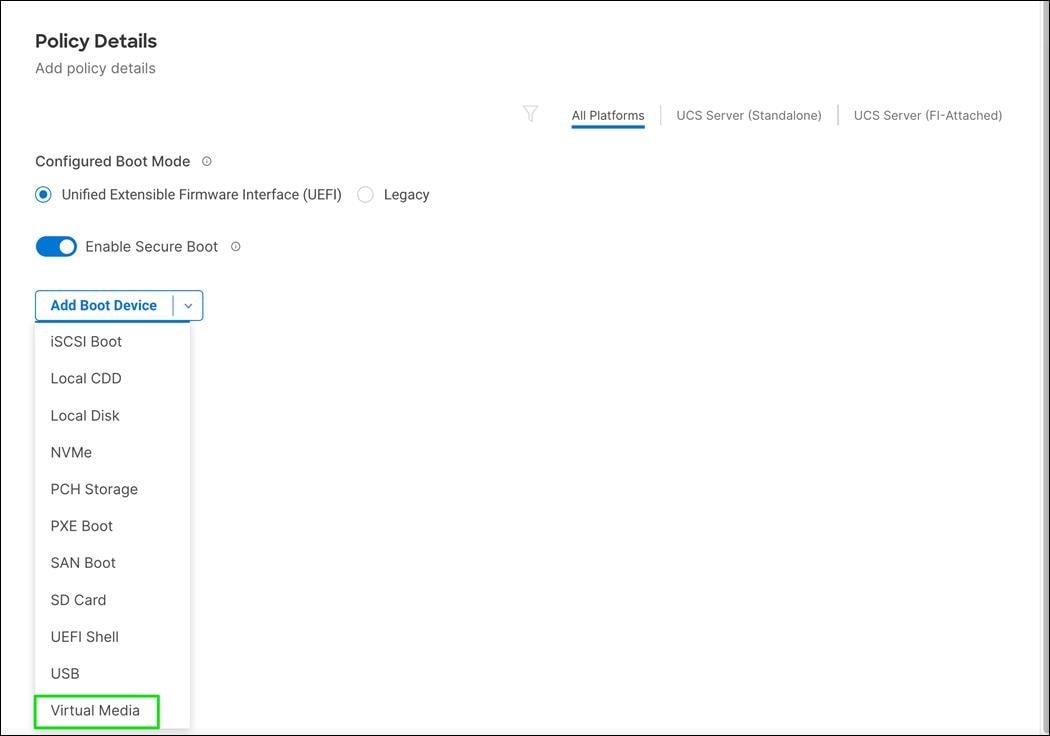
Step 8. Provide a device name (for example, KVM-Mapped-ISO) and then, for the subtype, select KVM Mapped DVD.

Step 9. From the Add Boot Device drop-down list, select SAN Boot.
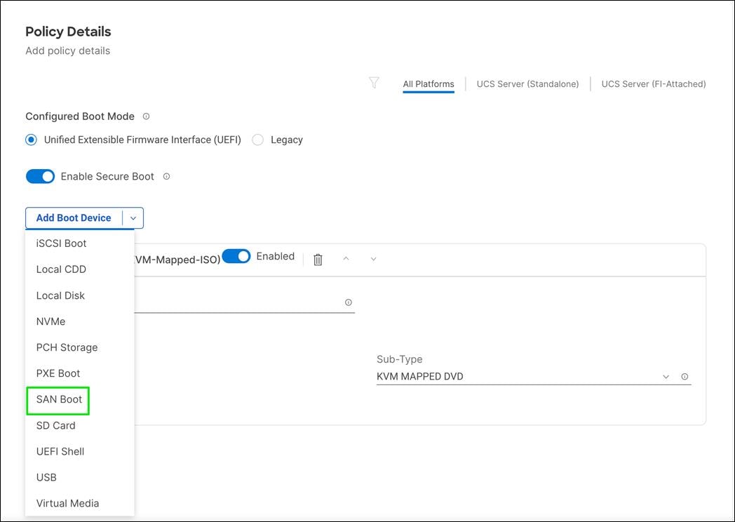
Step 10. Add four Pure Storage scsi-fc interfaces as boot options. The four interfaces are named as follows:
● FlashArray-CT0FC0: FlashArray Controller 0, FC0 (SAN-A)
● FlashArray-CT1FC0: FlashArray Controller 1, FC0 (SAN-A)
● FlashArray-CT0FC2: FlashArray Controller 0, FC1 (SAN-B)
● FlashArray-CT1FC2: FlashArray Controller 1, FC1 (SAN-B)
Note: vHBA-A is used to access CT0FC0 and CT1FC0 and vHBA-B is used to access CT0FC2 and CT1FC2.
Step 11. Provide the Device Name (for example, FlashArray-CT0FC0) and LUN ID (for example, 1).
Step 12. Provide an Interface Name (for example, vHBA-A) and note this name to be used for vHBA definition later. This value is important and should match the vHBA name.
Step 13. Add the appropriate WWPN value in the Target WWPN. This value can be obtained from Pure Storage FlashArray using “pureport list” command using the FlashArray//XL CLI or from the Connections tab under the Health section of the FlashArray//X with the Web GUI.
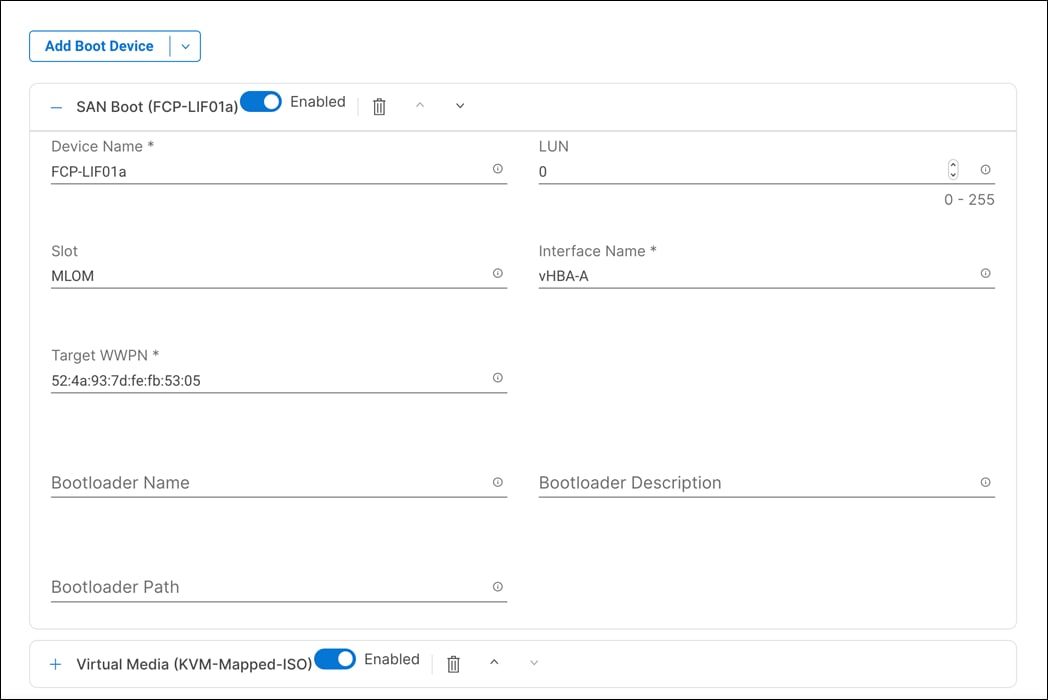
Step 14. Click SAN Boot again to add the second Pure FlashArray target on the Fabric A side.
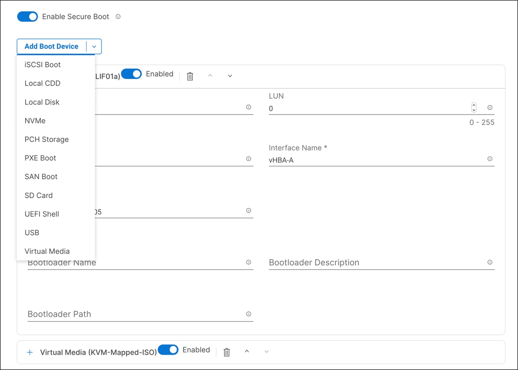
Step 15. Add details for second Pure FlashArray target on the Fabric A side.
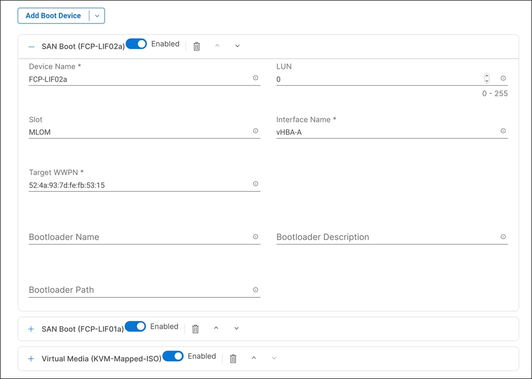
Step 16. Click SAN Boot again to add the third Pure FlashArray target on the Fabric B side.
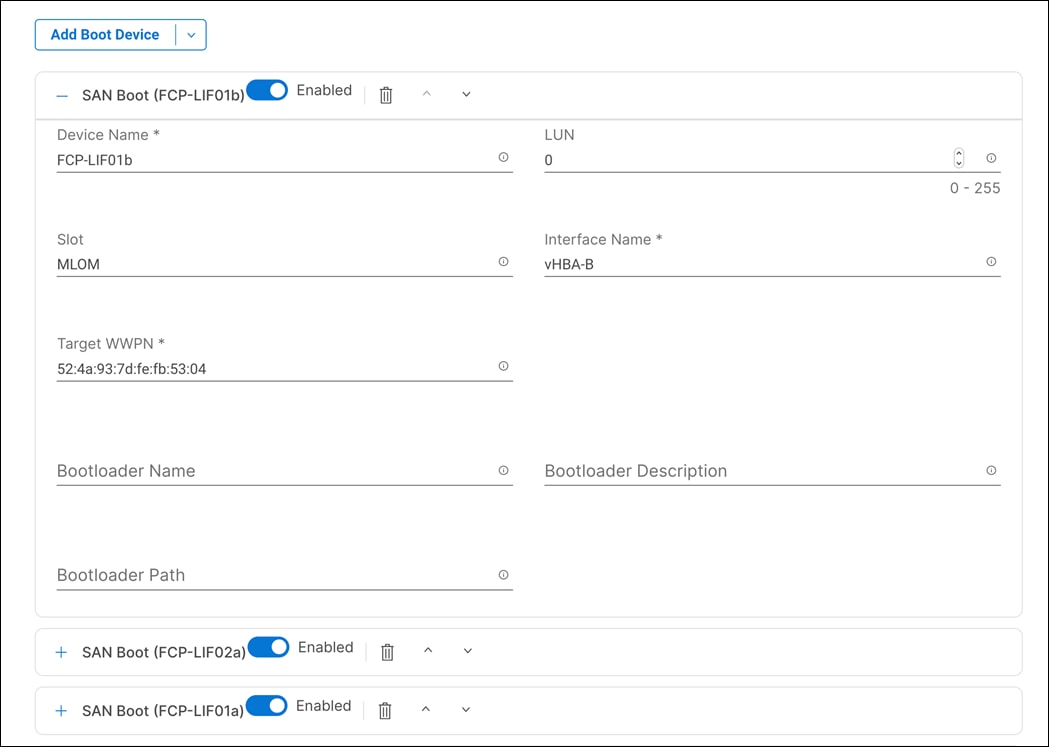
Step 17. Add the second Pure FlashArray target on the Fabric B side.
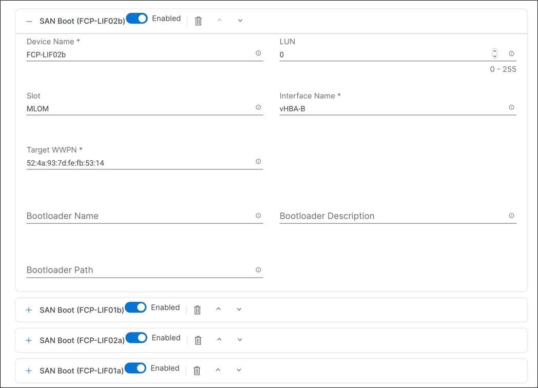
Step 18. Verify the order of the boot policies and adjust the boot order as necessary using the arrows.
After adding all the boot devices, the list should look like as shown below:
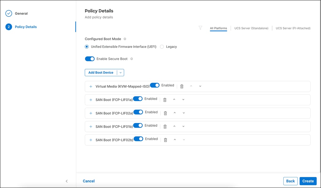
Step 19. Click Create.
Procedure 6. Configure Virtual Media Policy
Step 1. Click Select Policy next to Virtual Media.
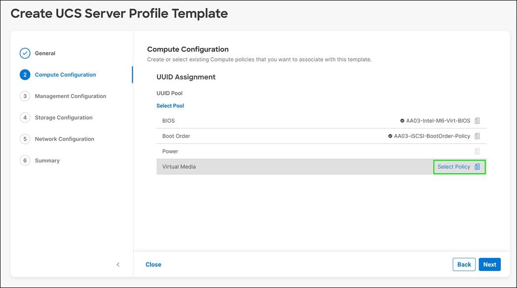
Step 2. Click Select Policy next to Virtual Media.
Step 3. In the pane on the right, click Create New.
Step 4. Verify the correct organization is selected from the drop-down list (for example, FlashStack) and provide a name for the policy (for example, AA03-vMedia-Policy).

Step 5. Make sure all virtual media configuration options are selected.
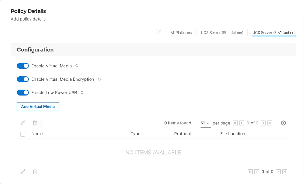
Step 6. You can optionally add a virtual media ISO if you prefer this approach over manually attaching ISO when server boot. To attach a Virtual media, click on Add Virtual Media and fill the details.
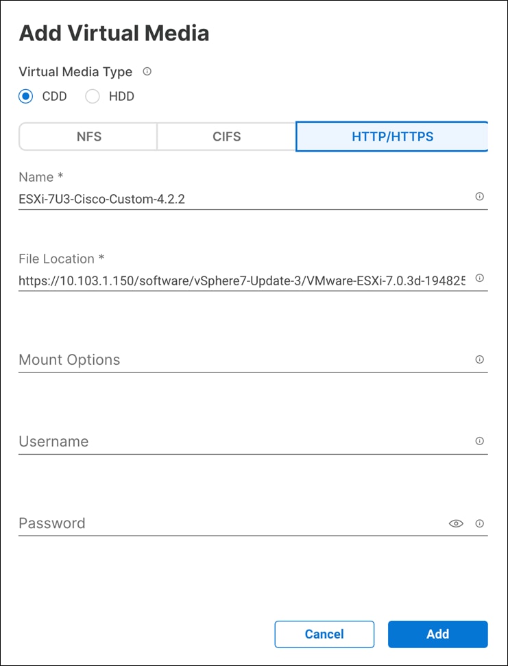
Step 7. Click Add.
Step 8. Click Create.
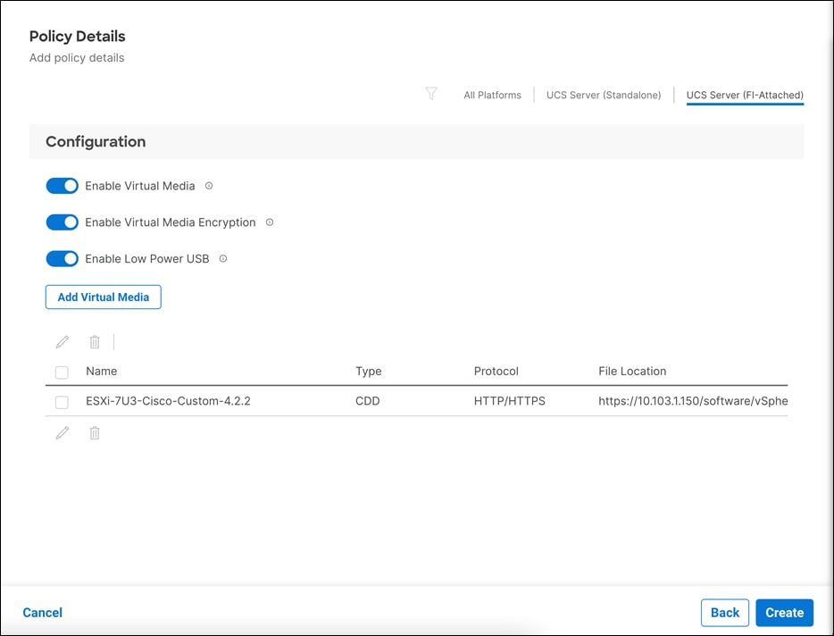
Step 9. Click Next for Management Configuration.
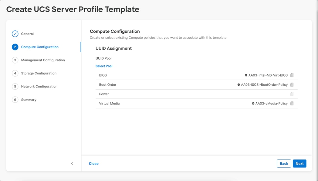
Management Configuration
Configure the management policy. These policies will be added to the management configuration:
· Certificate Management Policy (Optional) to use external certificates
· IMC Access to define the pool of IP addresses for compute node KVM access
· IPMI Over LAN to allow Intersight to manage IPMI messages
· Local User to provide local administrator to access KVM
· Virtual KV Policy to enable virtual KVM and set Tunneled KVM to true
Procedure 1. Configure Certificate Management Policy (Optional)
The Certificate Management policy allows you to specify the certificate and private key-pair details for an external certificate and attach the policy to servers for IMC access.
Step 1. Click Select Policy next to Certificate Management.
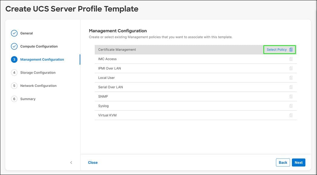
Step 2. In the pane on the right, click Create New.
Step 3. Verify the correct organization is selected from the drop-down list (for example, FlashStack) and provide a name for the policy (for example, AA03-Cert-Policy).

Step 4. Click Next.
Step 5. Enter the certificate details and Private Key.
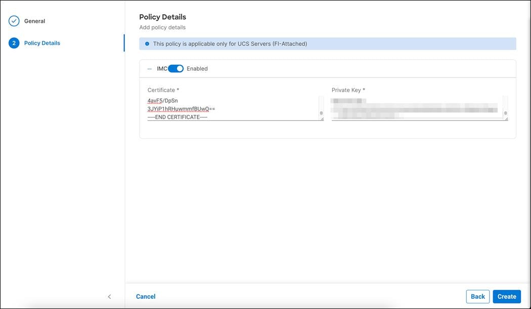
Step 6. Click Create.
Procedure 2. Configure IMC Access Policy
Step 1. Click Select Policy next to IMC Access and in the pane on the right.
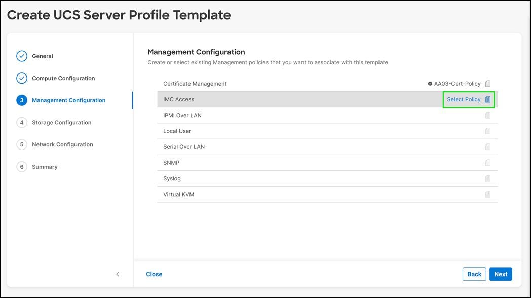
Step 2. Click Create New.
Step 3. Verify the correct organization is selected from the drop-down list (for example, FlashStack) and provide a name for the policy (for example, AA03-IMC-Access).

Step 4. Click Next.
Note: You can select in-band management access to the compute node using an in-band management VLAN or out-of-band management access via the Mgmt0 interfaces of the FIs. KVM Policies like SNMP, vMedia and Syslog are currently not supported via Out-Of-Band and will require an In-Band IP to be configured. Since these policies were not configured in this deployment, out-of-band management access was configured so that KVM access to compute nodes is not impacted by any potential switching issues in the fabric.
Step 5. Click UCS Server (FI-Attached).
Step 6. Provide the out-of-band management VLAN ID (for example, 1030).
Step 7. Click Select IP Pool for defining a KVM IP address assignment pool.
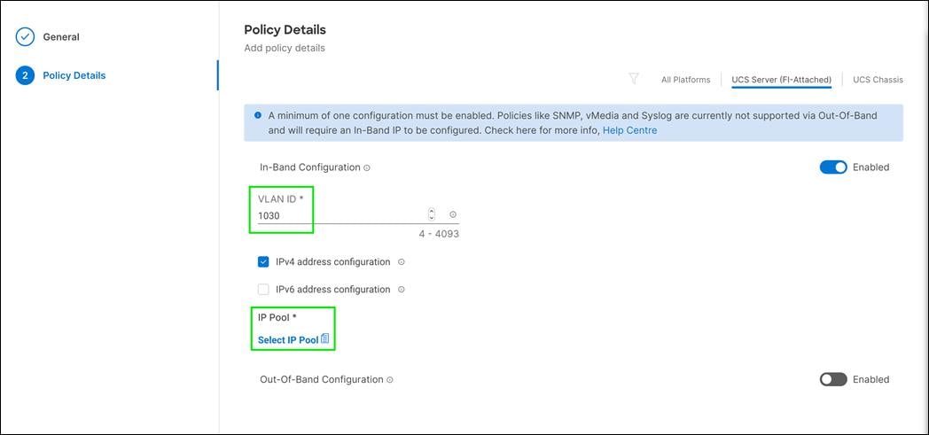
Step 8. In the pane on the right, click Create New.
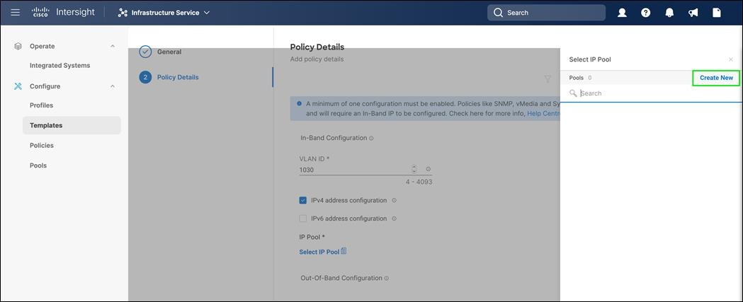
Step 9. Verify the correct organization is selected from the drop-down list (for example, FlashStack) and provide a name for the pool (for example, AA03-Mgmt-IP-Pool).

Step 10. Click Next.
Step 11. Select Configure IPv4 Pool and provide the information to define a pool for KVM IP address assignment including an IP Block.
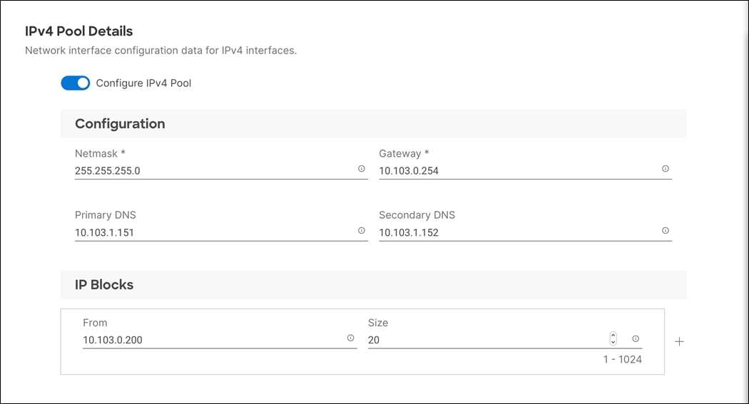
Step 12. Deselect Configure IPv6 Pool.
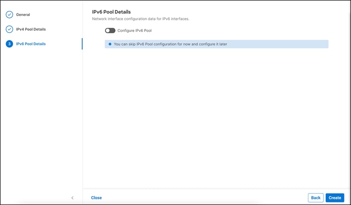
Step 13. Click Create to finish configuring the IP address pool.
Step 14. Click Create to finish configuring the IMC access policy
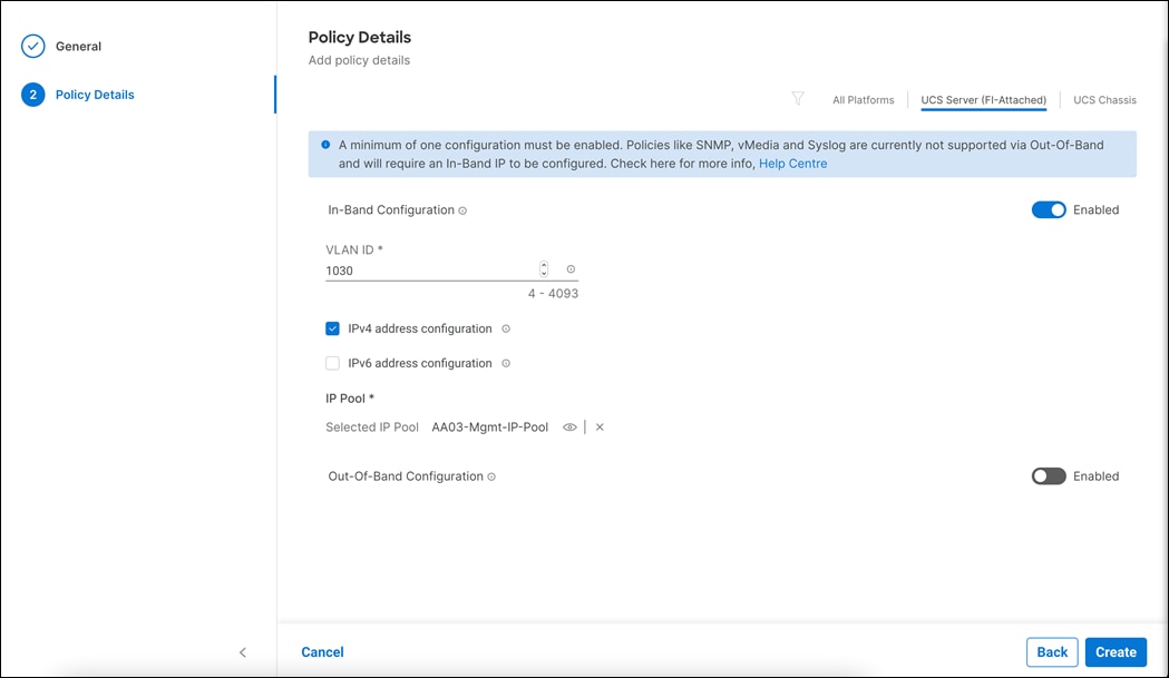
Procedure 3. Configure IPMI Over LAN Policy
Step 1. Click Select Policy next to IPMI Over LAN and then, in the pane on the right.
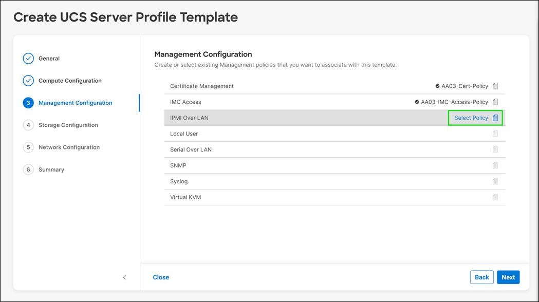
Step 2. Click Create New.
Step 3. Verify the correct organization is selected from the drop-down list (for example, FlashStack) and provide a name for the policy (for example, AA03-IPMIoLAN-Policy).
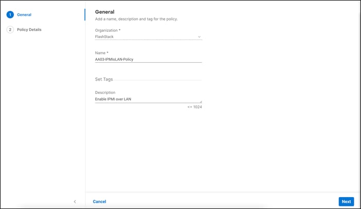
Step 4. Turn on Enable IPMI Over LAN.
Step 5. From the Privilege Level drop-down list, select admin.
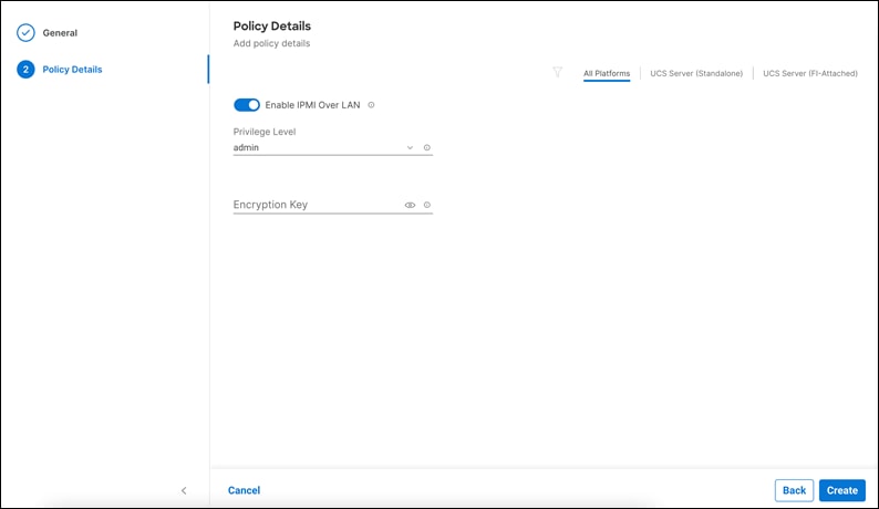
Step 6. Click Create.
Procedure 4. Configure Local User Policy
Step 1. Click Select Policy next to Local User and in the pane on the right.
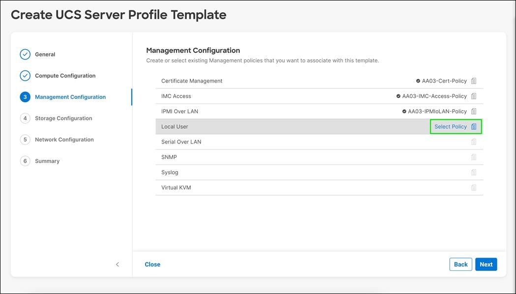
Step 2. Click Create New.
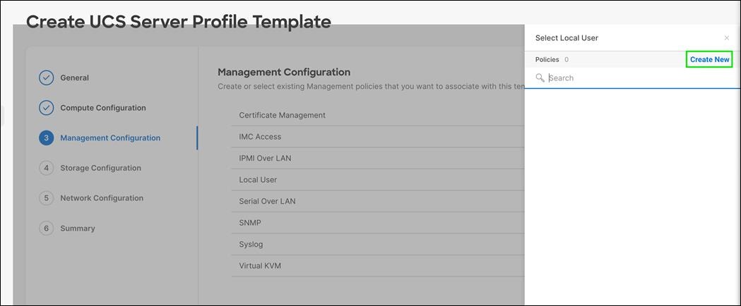
Step 3. Verify the correct organization is selected from the drop-down list (for example, FlashStack) and provide a name for the policy (for example, AA03-LocalUser-Policy).
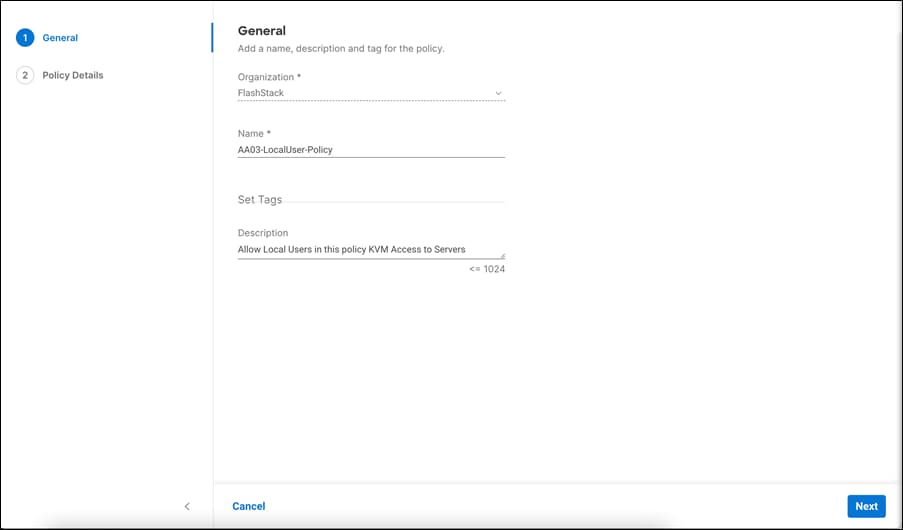
Step 4. Click Next.
Step 5. Verify UCS Server (FI-Attached) is selected.
Step 6. Verify Enforce Strong Password is selected.
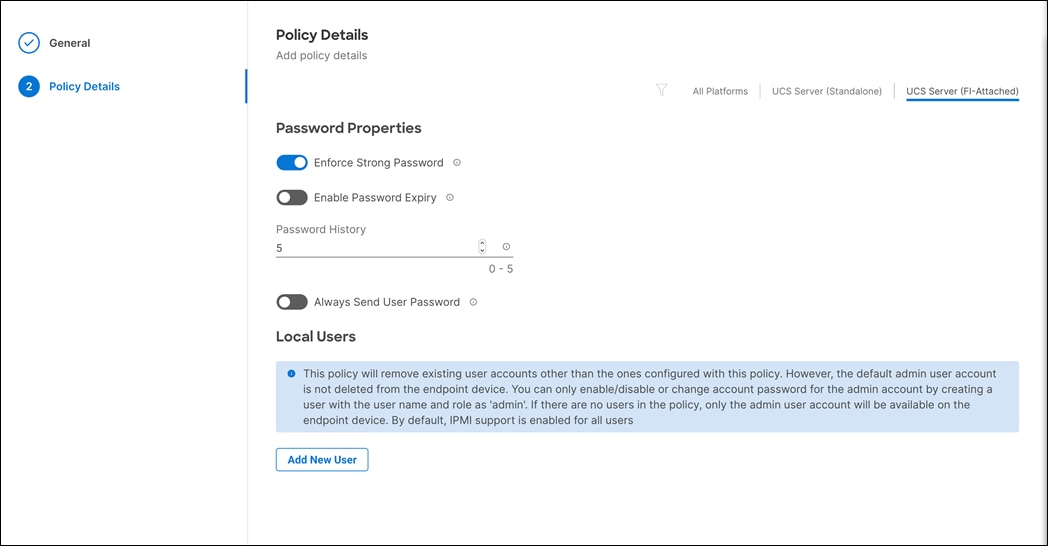
Step 7. Click Add New User and then click + next to the New User.
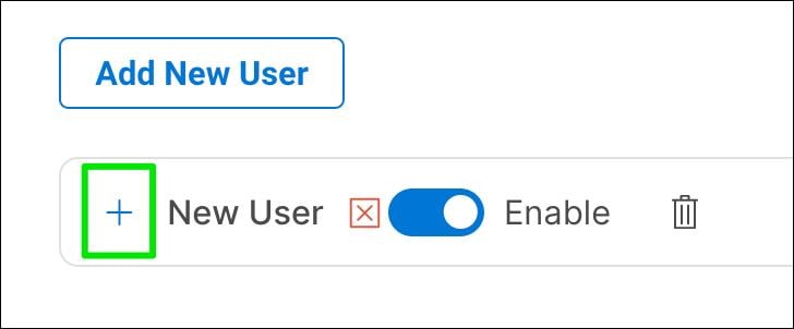
Step 8. Provide the Username (for example, flashadmin), Role (for example, admin) and the password.
Note: The username and password combination defined here will be used to log into KVMs. The typical UCS admin/password combination cannot be used for KVM access.
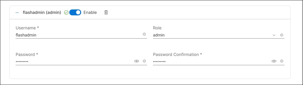
Step 9. Click Create to finish configuring the user.
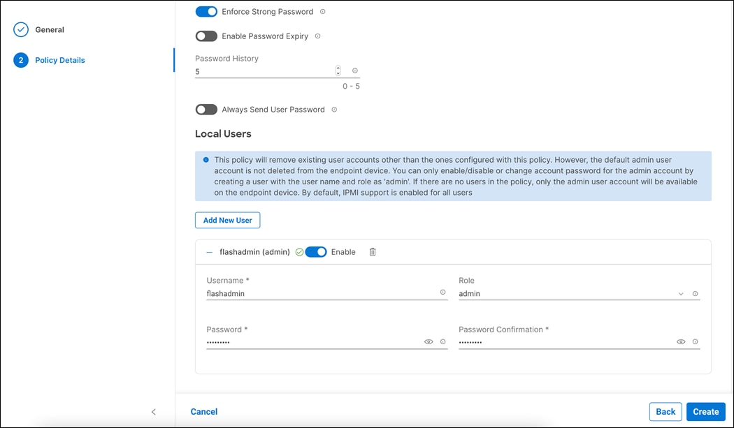
Step 10. Click Create to finish configuring Local User Policy.
Procedure 5. Configure Virtual KVM Policy
Step 1. Click Select Policy next to Virtual KVM.
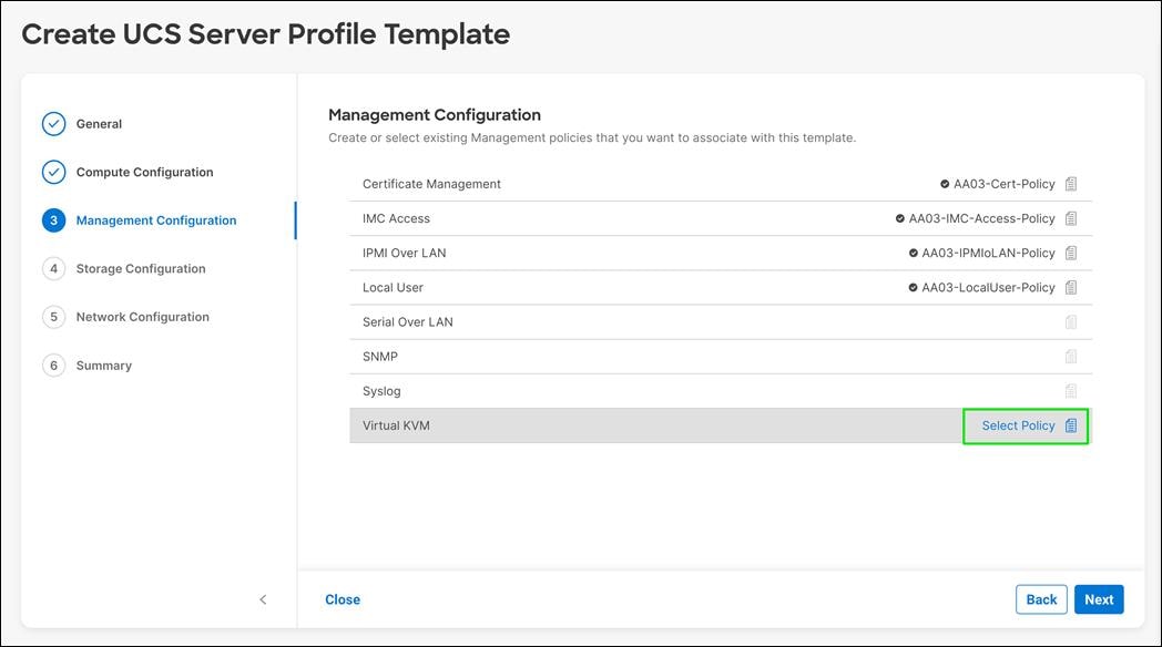
Step 2. In the pane on the right, click Create New.
Step 3. Verify the correct organization is selected from the drop-down list (for example, FlashStack) and provide a name for the policy (for example, AA03-KVM-Policy).

Step 4. Click Next
Step 5. Select All Platforms.
Step 6. Enable Allow Tunneled vKVM. This Enables Tunneled vKVM on the endpoint. Applicable only for Device Connectors that support Tunneled vKVM.
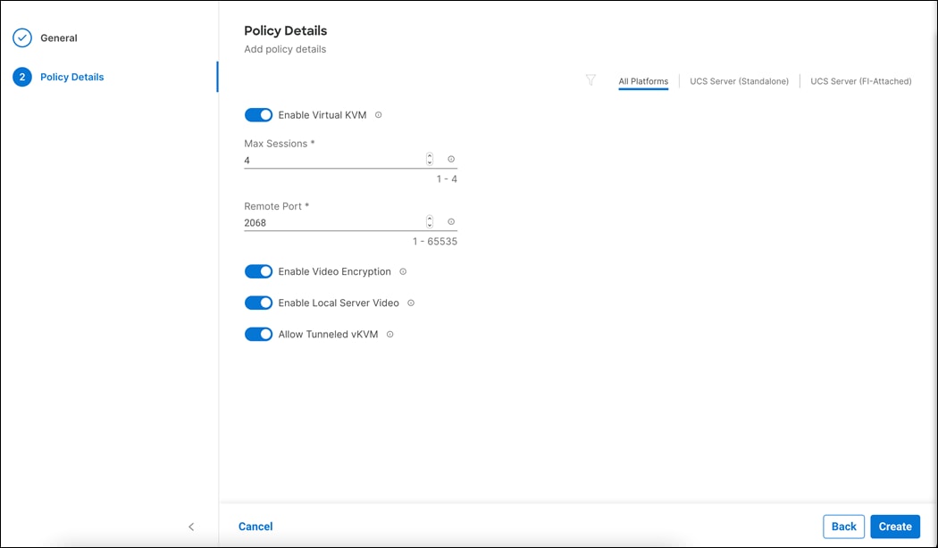
Step 7. Click Create.
Step 8. Click Next to move to Storage Configuration.
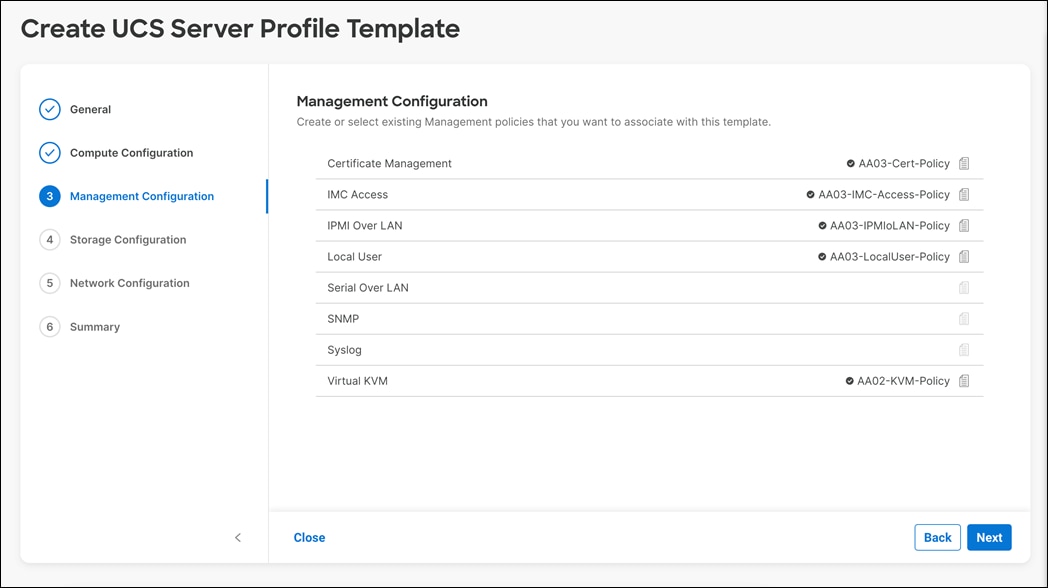
Procedure 6. Storage Configuration
Step 1. Click Next on the Storage Configuration screen. No configuration is needed in the local storage system.
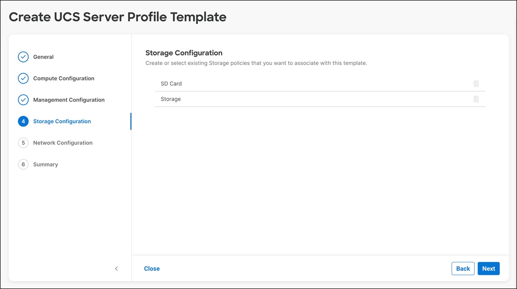
Network Configuration – LAN Connectivity Policy
LAN connectivity policy defines the connections and network communication resources between the server and the LAN. This policy uses pools to assign MAC addresses to servers and to identify the vNICs that the servers use to communicate with the network. For iSCSI hosts, this policy also defined an IQN address pool.
For consistent vNIC and vHBA placement, manual vHBA/vNIC placement is utilized. iSCSI boot from SAN hosts and FC boot from SAN hosts require different number of vNICs/vHBAs and different placement order therefore the iSCSI host and the FC host LAN connectivity policies are explained separately in this section.
LAN Connectivity Policy for iSCSI Hosts
The iSCSI boot from SAN hosts uses 6 vNICs configured as listed in Table 16:
Table 16. vNICs for iSCSI LAN Connectivity
| vNIC/vHBA Name |
Slot ID |
Switch ID |
PCI Order |
VLANs |
| 00-vSwitch0-A |
MLOM |
A |
0 |
OOB-MGMT-VLAN IB-MGMT-VLAN |
| 01-vSwitch0-B |
MLOM |
B |
1 |
OOB-MGMT-VLAN IB-MGMT-VLAN |
| 02-VDS0-A |
MLOM |
A |
2 |
VM Traffic vMotion |
| 03-VDS0-B |
MLOM |
B |
3 |
VM Traffic, vMotion |
| 04-iSCSI-A |
MLOM |
A |
4 |
iSCSI-A-VLAN |
| 05-iSCSI-B |
MLOM |
B |
5 |
iSCSI-B-VLAN |
Procedure 1. Create LAN Connectivity Policy for iSCSI Hosts
Step 1. Click Select Policy next to LAN Connectivity.
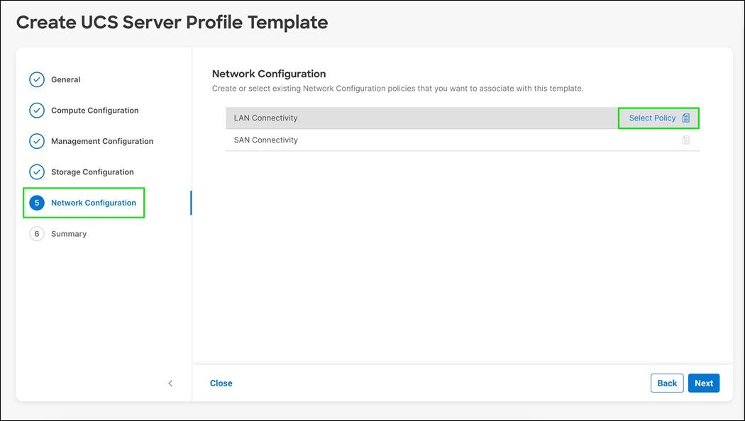
Step 2. In the pane on the right, click Create New.
Step 3. Verify the correct organization is selected from the drop-down list (for example, FlashStack) and provide a name for the policy (for example, AA03-iSCSI-LAN-Conn-Policy).

Step 4. Click Next.
Step 5. Under IQN, select Pool.
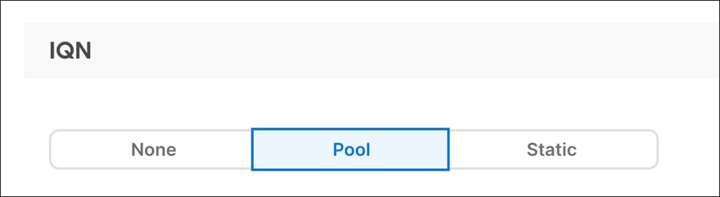
Step 6. Click Select Pool under IQN Pool.
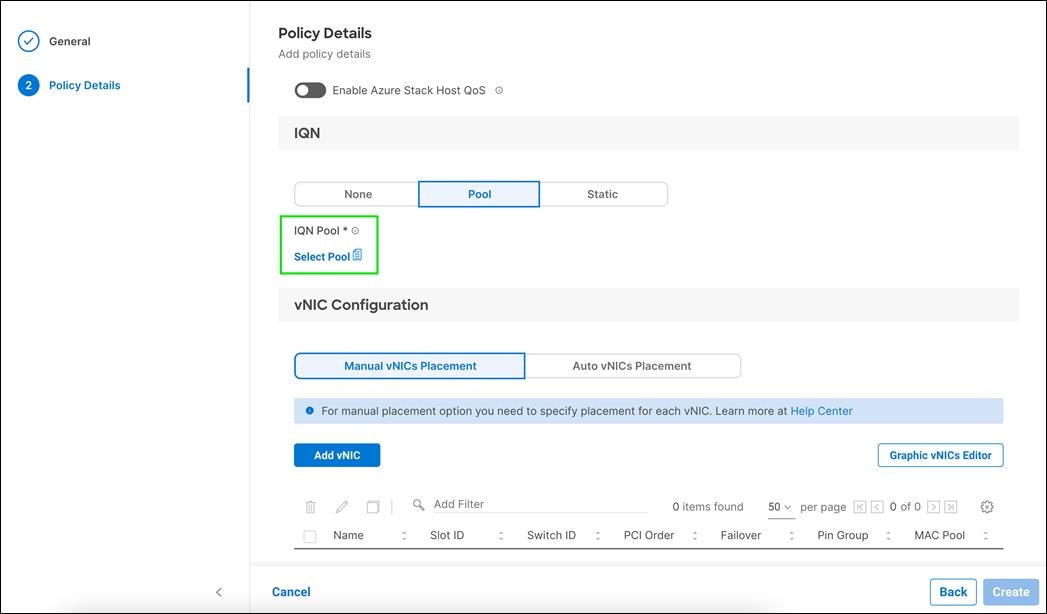
Step 7. In the pane on the right, click Create New.
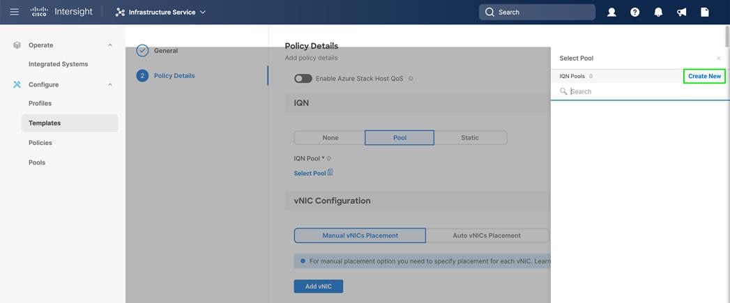
Step 8. Verify correct organization is selected from the drop-down list (for example, FlashStack) and provide a name for the policy (for example, AA03-IQN-Pool).
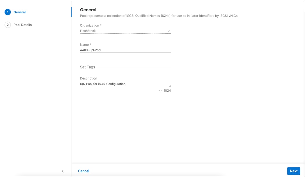
Step 9. Click Next.
Step 10. Provide the values for Prefix and IQN Block to create the IQN pool.
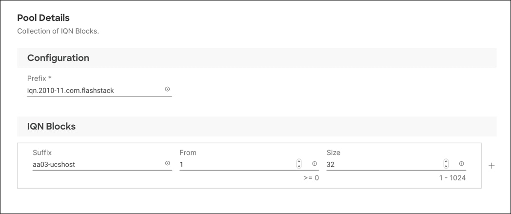
Step 11. Click Create.
Step 12. Under vNIC Configuration, select Manual vNICs Placement.
Step 13. Click Add vNIC.
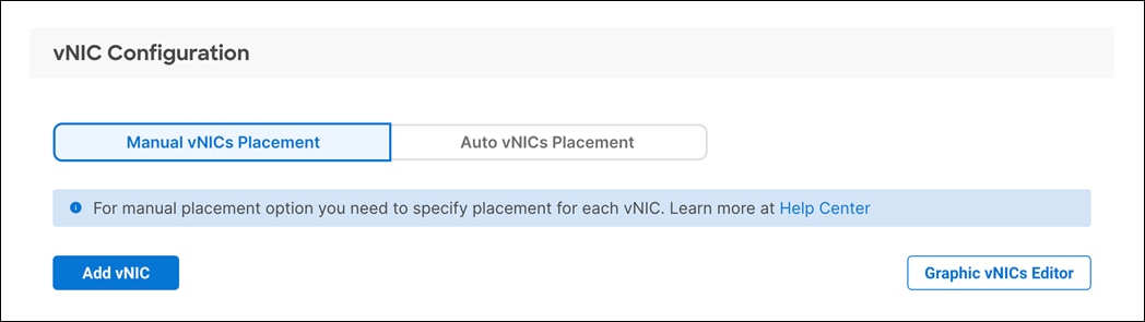
Create MAC Address Pool
When creating the first vNIC, the MAC address pool has not been defined yet therefore a new MAC address pool will need to be created. Two separate MAC address pools are configured for each Fabric. MAC-Pool-A will be reused for all Fabric-A vNICs, and MAC-Pool-B will be reused for all Fabric-B vNICs, see Table 17.
| Pool Name |
Starting MAC Address |
Size |
| AA03-Mac-Pool-A |
00:B4:AA:03:0A:00 |
128* |
| AA03-Mac-Pool-B |
00:B4:AA:03:0B:00 |
128* |
Note: Each server requires 3 MAC addresses from the pool. Adjust the size of the pool according to your requirements.
Procedure 1. Define the MAC Pool for Fabric A and B
Step 1. Click Select Pool under MAC Address Pool.
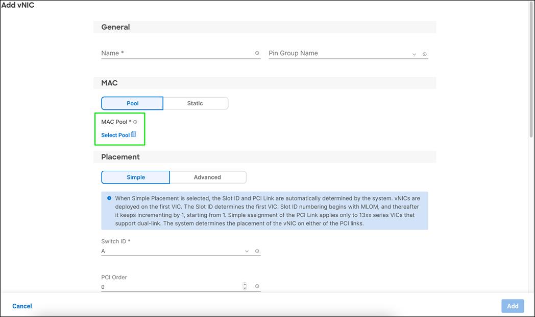
Step 2. In the pane on the right, click Create New.
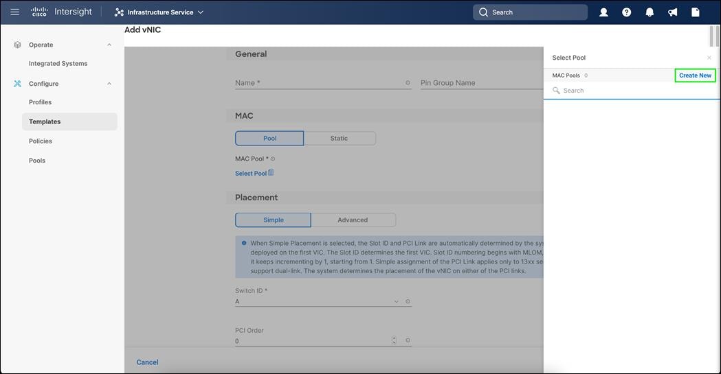
Step 3. Verify correct organization is selected from the drop-down list (for example, FlashStack) and provide a name for the pool from Table 17 depending on the vNIC being created (for example, AA03-Mac-Pool-A for Fabric A).
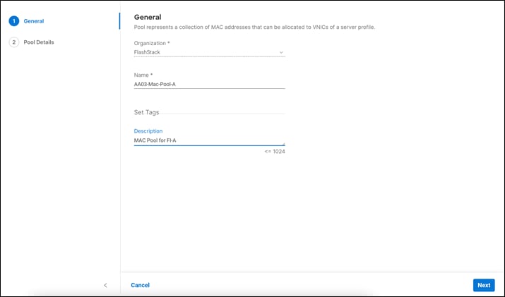
Step 4. Click Next.
Step 5. Provide the starting MAC address (For example: 00:B4:AA:03:0A:00).
Note: For ease of troubleshooting FlashStack datacenter, some additional information is always coded into the MAC address pool. For example, in the starting address 00:B4:AA:03:0A:00, AA is the row and 03 is the rack ID and 0A indicates Fabric A.
Step 6. Provide the size of the MAC address pool (for example, 128).
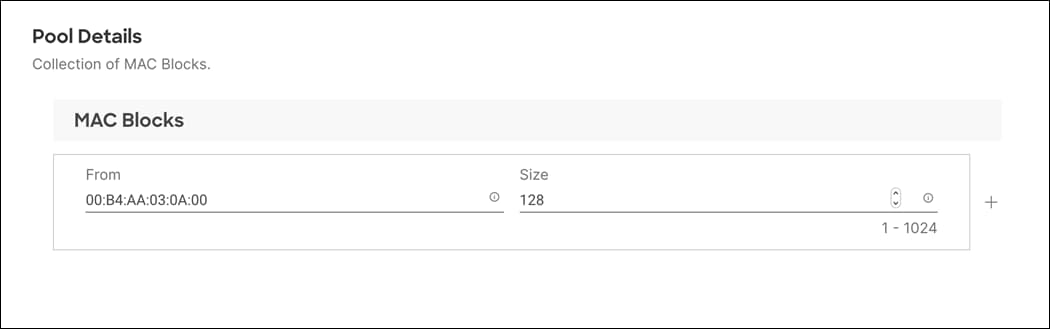
Step 7. Click Create to finish creating the MAC address pool.

Step 8. From the Add vNIC window, select Advanced for Placement.

Step 9. Provide vNIC Name, Slot ID, Switch ID, and PCI Order information as per vNICs for iSCSI LAN Connectivity table.
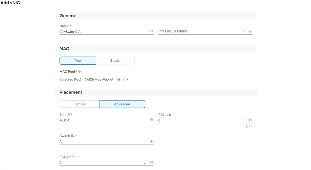
Step 10. For Consistent Device Naming (CDN), from the drop-down list, select vNIC Name.
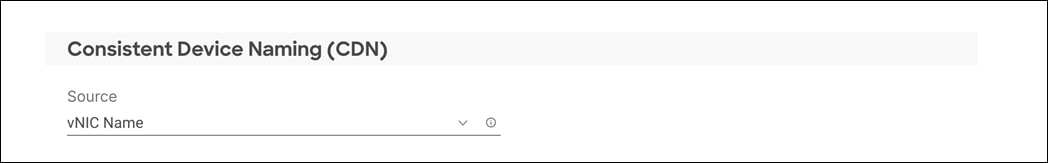
Step 11. Verify that Failover is disabled because the failover will be provided by attaching multiple NICs to the VMware vSwitch and VDS.
Create Ethernet Network Group Policy
Ethernet Network Group policies will be created and reused on applicable vNICs as covered below. Ethernet network group policy defines the VLANs allowed for a particular vNIC therefore multiple network group policies will be defined for this deployment as list in Table 18:
Table 18. Ethernet Network Group Policy Values
| Group Policy Name |
Native VLAN |
Allowed VLANs |
Apply to vNICs |
| AA03-vSwitch0-NetGrp-Policy |
Native-VLAN (3) |
1031,1030 |
00-vSwitch0-A 01-vSwitch0-B |
| AA03-VDS0-NetGrp-Policy |
Native-VLAN (3) |
3319,1032,1031,1030 |
02-VDS0-A 03-VDS0-B |
| AA03-iSCSI-A-NetGrp-Policy |
iSCSI-A-VLAN (3119) |
3119 |
05-iSCSI-A |
| AA03-iSCSI-B-NetGrp-Policy |
iSCSI-B-VLAN (3219) |
3219 |
06-iSCSI-B |
Procedure 1. Define Ethernet Group Policy for a vNIC
Step 1. Click Select Policy under Ethernet Network Group Policy.
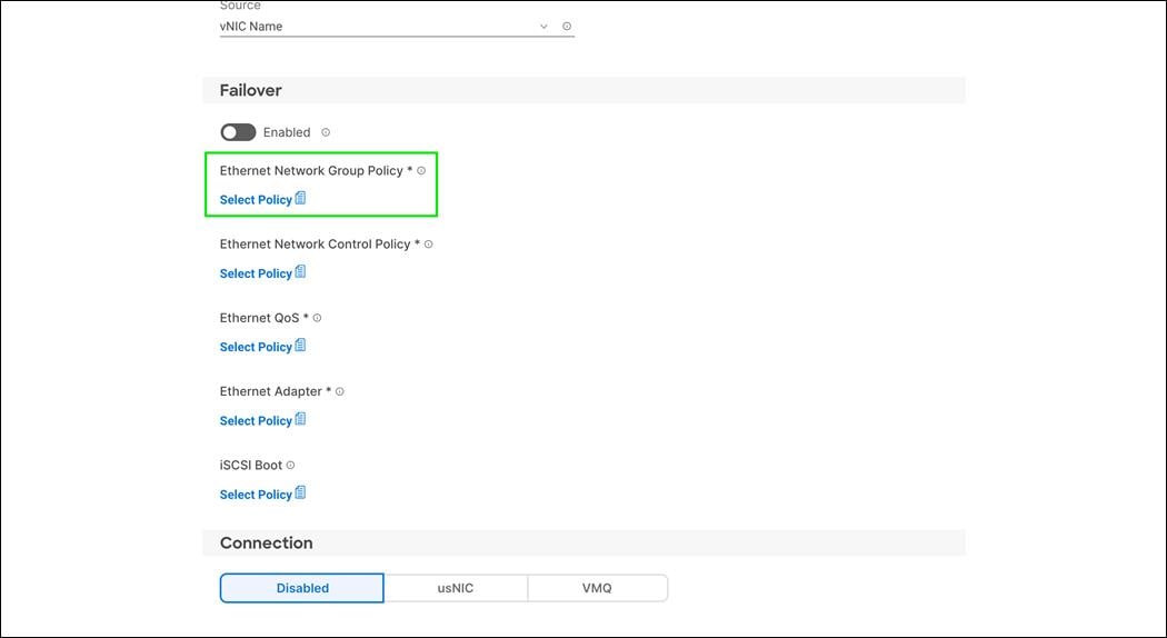
Step 2. In the pane on the right, click Create New.
Step 3. Verify correct organization is selected from the drop-down list (for example, FlashStack) and provide a name for the policy (for example, AA03-vSwitch0-NetGrp-Policy).

Step 4. Click Next.
Step 5. Enter the allowed VLANs (for example, 1030,1031) and the native VLAN ID (for example, 3) as listed int Table 18.

Step 6. Click Create to finish configuring the Ethernet network group policy.
Step 7. Repeat steps 1 – 6 to create AA03-VDS0-NetGrp-Policy.
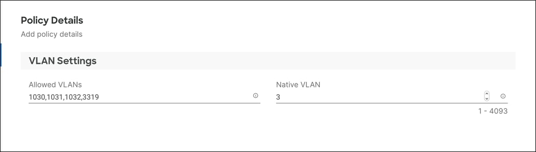
Step 8. Repeat steps 1 – 6 to create AA03-iSCSI-A-NetGrp-Policy.
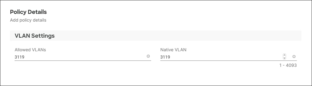
Step 9. Repeat steps 1 – 6 to create AA03-iSCSI-B-NetGrp-Policy.
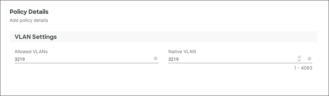
Note: When ethernet group policies are shared between two vNICs, the ethernet group policy only needs to be defined for the first vNIC. For subsequent vNIC policy mapping, click Select Policy and select the previously defined ethernet group policy from the list on the right.
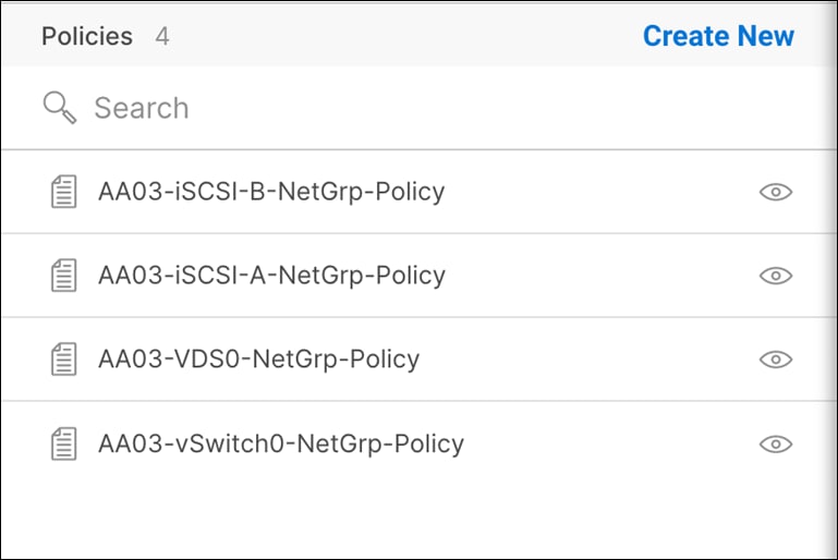
Create Ethernet Network Control Policy
Ethernet Network Control Policy is used to enable Cisco Discovery Protocol (CDP) and Link Layer Discovery Protocol (LLDP) for the vNICs. A single policy will be created here and reused for all the vNICs.
Procedure 1. Ethernet Network Control Policy
Step 1. Click Select Policy under Ethernet Network Control Policy.
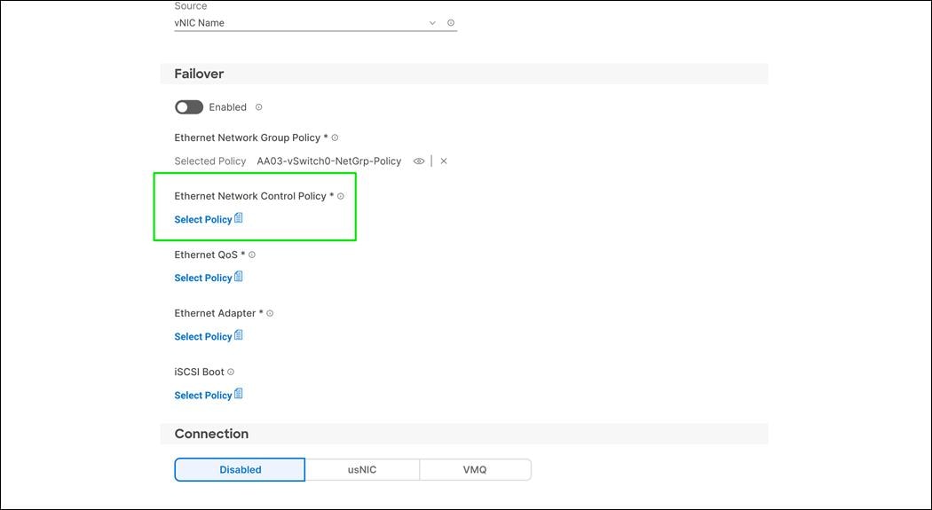
Step 2. In the pane on the right, click Create New.
Step 3. Verify correct organization is selected from the drop-down list (for example, FlashStack) and provide a name for the policy (for example, AA03-Enable-CDP-LLDP-Policy).

Step 4. Click Next.
Step 5. Enable Cisco Discovery Protocol and both Enable Transmit and Enable Receive under LLDP.
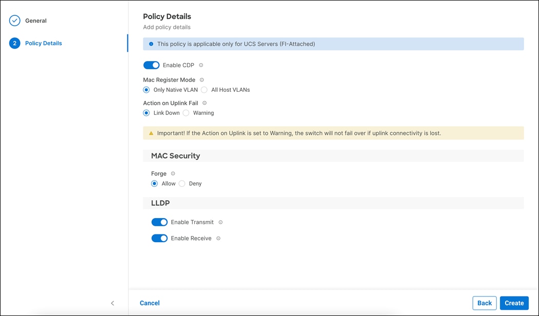
Step 6. Click Create to finish creating Ethernet network control policy.
Procedure 2. Create Ethernet QoS policy
Ethernet QoS policy is used to enable jumbo maximum transmission units (MTUs) for all the vNICs. A single policy will be created and reused for all the vNICs.
Step 1. Click Select Policy under Ethernet QoS.
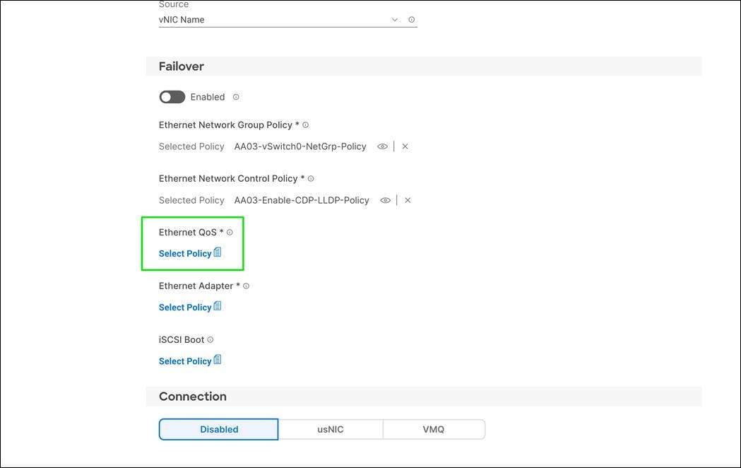
Step 2. In the pane on the right, click Create New.
Step 3. Verify correct organization is selected from the drop-down list (for example, FlashStack) and provide a name for the policy (for example, AA03-EthernetQoS-Policy).
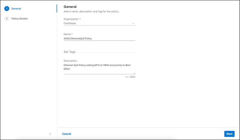
Step 4. Click Next.
Step 5. Change the MTU, Bytes value to 9000.
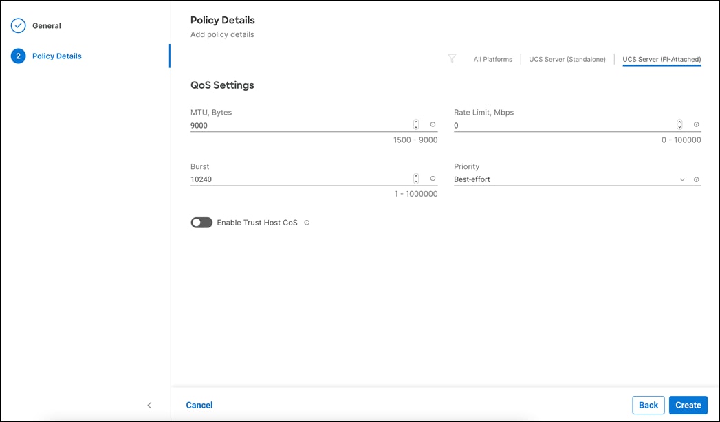
Step 6. Click Create to finish setting up the Ethernet QoS policy.
Create Ethernet Adapter Policy
Ethernet adapter policy is used to set the interrupts and the send and receive queues. The values are set according to VIC capabilities and best-practices guidance for the operating system in use. Cisco Intersight provides default VMware Ethernet Adapter policy for typical VMware deployments.
Customers can optionally configure a tweaked ethernet adapter policy for additional hardware receive queues handled by multiple CPUs in scenarios where there is a lot of vMotion traffic and multiple flows.
In this deployment, the following modified ethernet adapter policies are created for performance:
· AA03-VMware-High-Traffic - Created and attached to interfaces which handle vMotion and VMTraffic
· AA03-EthAdapter-16RXQs-5G - Created and attached to vNICs which handle iSCSI traffic on server installed with Cisco UCS X210c M6 compute node installed with 5th Generation Cisco VIC 15231
· AA03-EthAdapter-16RXQs-4G - Created and attached to vNICs which handle iSCSI traffic on server installed with 4th Gen VIC adapter installed either on X210c M6, B200M6 or AMD based C225 M6 and C245 M6 servers (Example – Cisco UCS Virtual Interface Card 1495)
Table 19. Summary of Ethernet Adapter Policy Association to vNICs
| Policy Name |
vNICs |
| AA03-EthAdapter-VMware |
00-vSwitch0-A 01-vSwitch0-B |
| AA03-EthAdapter-HighTraffic |
02-VDS0-A 03-VDS0-B |
| AA03-EthAdapter-16RXQs-5G Use this policy if servers are installed with 5th Gen VIC card |
04-iSCSI-A 05-iSCSI-B |
| AA03-EthAdapter-16RXQs-4G Use this policy if servers are installed with 4th Gen VIC card |
04-iSCSI-A 05-iSCSI-B |
Procedure 1. Create the Ethernet Adapter Policy
Step 1. Click Select Policy under Ethernet Adapter.
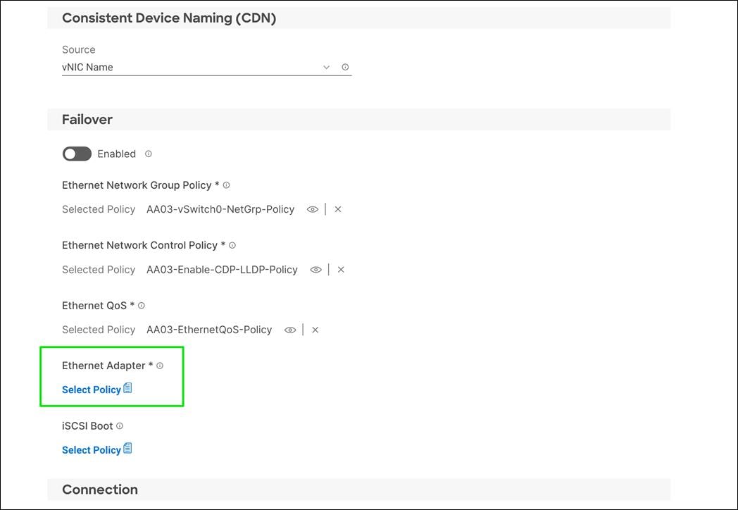
Step 2. In the pane on the right, click Create New.
Step 3. Verify correct organization is selected from the drop-down list (for example, FlashStack) and provide a name for the policy (for example, AA03-EthAdapter-VMware).
Step 4. Click Select Default Configuration under Ethernet Adapter Default Configuration.
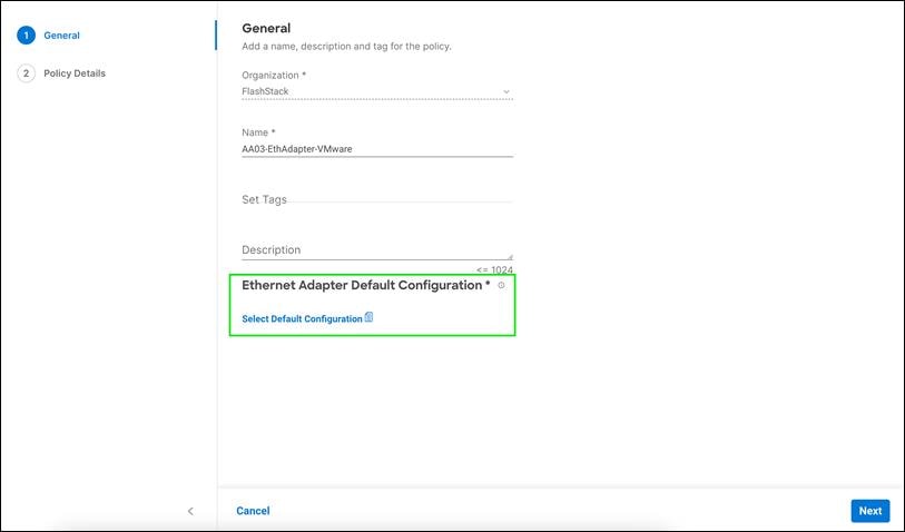
Step 5. From the list, select VMware.
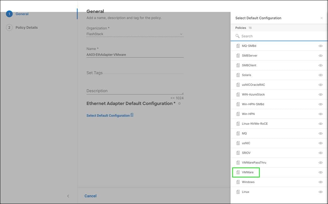
Step 6. Click Next.
Step 7. For the AA03-EthAdapter-VMware policy, click Create and skip the rest of the steps in this “Create the Ethernet Adapter Policy” section.
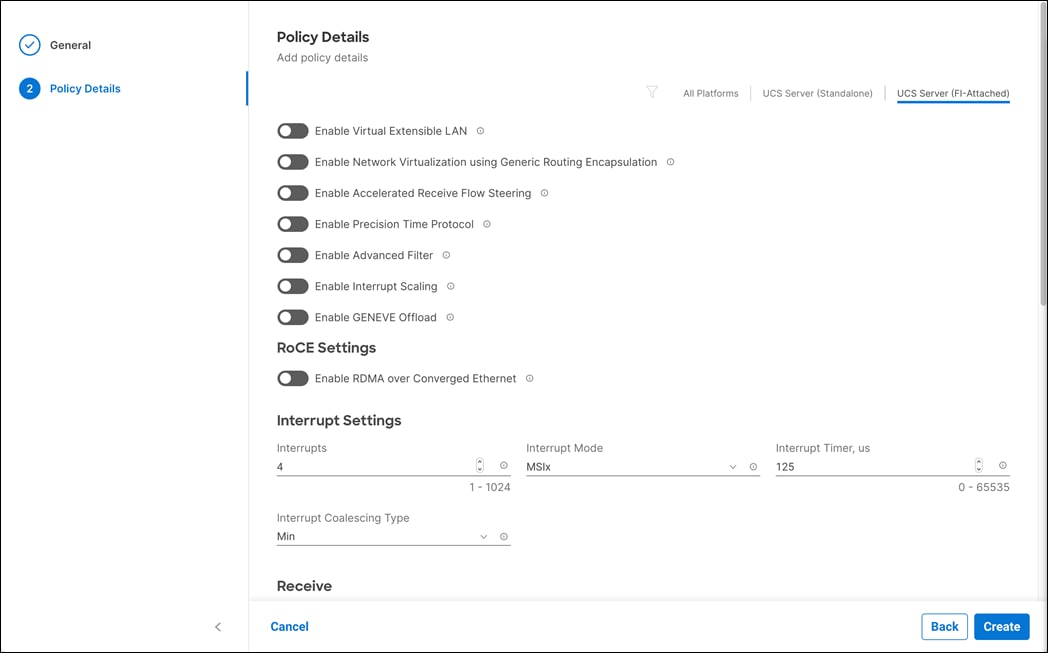
Step 8. For AA03-EthAdapter-HighTraffic policy, make the following modifications to the policy:
● Increase Interrupts to 11
● Increase Receive Queue Count to 8
● Increase Receive Ring Size to 4096
● Increase Transmit Ring Size to 4096
● Increase Completion Queue Count to 9
● Enable Receive Side Scaling
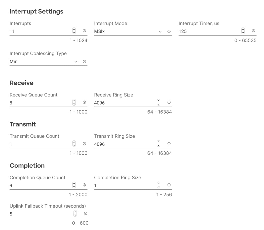

Step 9. For AA03-EthAdapter-16RXQs-5G policy, make the following modifications to the policy:
● Increase Interrupts to 19
● Increase Receive Queue Count to 16
● Increase Receive Ring Size to 16384
● Increase Transmit Ring Size to 16384
● Increase Completion Queue Count to 17
● Enable Receive Side Scaling
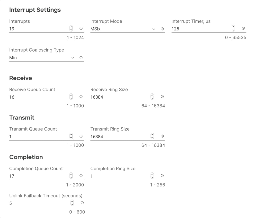
Step 10. For AA03-EthAdapter-16RXQs-4G policy, make the following modifications to the policy:
● Increase Interrupts to 19
● Increase Receive Queue Count to 16
● Increase Receive Ring Size to 4096
● Increase Transmit Ring Size to 4096
● Increase Completion Queue Count to 17
● Enable Receive Side Scaling
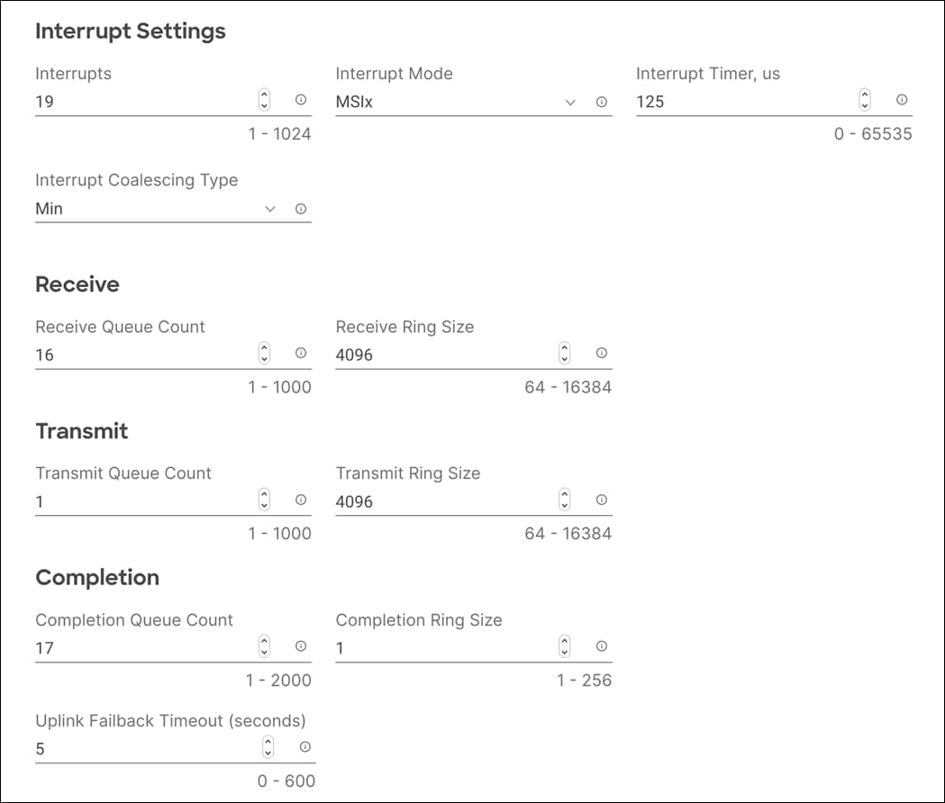
Note: For all the non-ISCSI vNIC, skip the iSCSI-A and iSCSI-B policy creation sections.
Create iSCSI-A Policy
iSCSI-A policy only applied to vNICs 04-ISCSI-A and should not be created for data vNICs (vSwitch0 and VDS). The iSCSI-B policy creation is explained in the following section.
Procedure 1. Create the iSCSI Boot Policy
Step 1. Click Select Policy under iSCSI Boot.
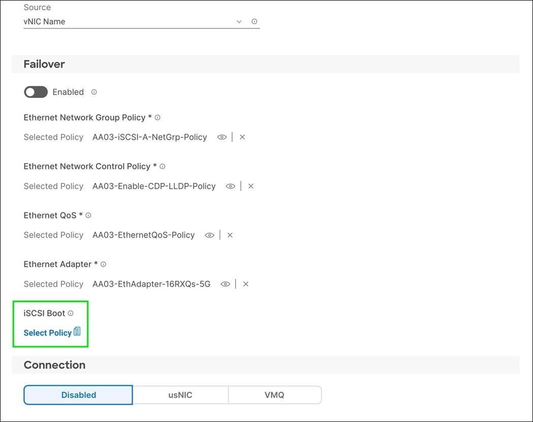
Step 2. In the pane on the right, click Create New.
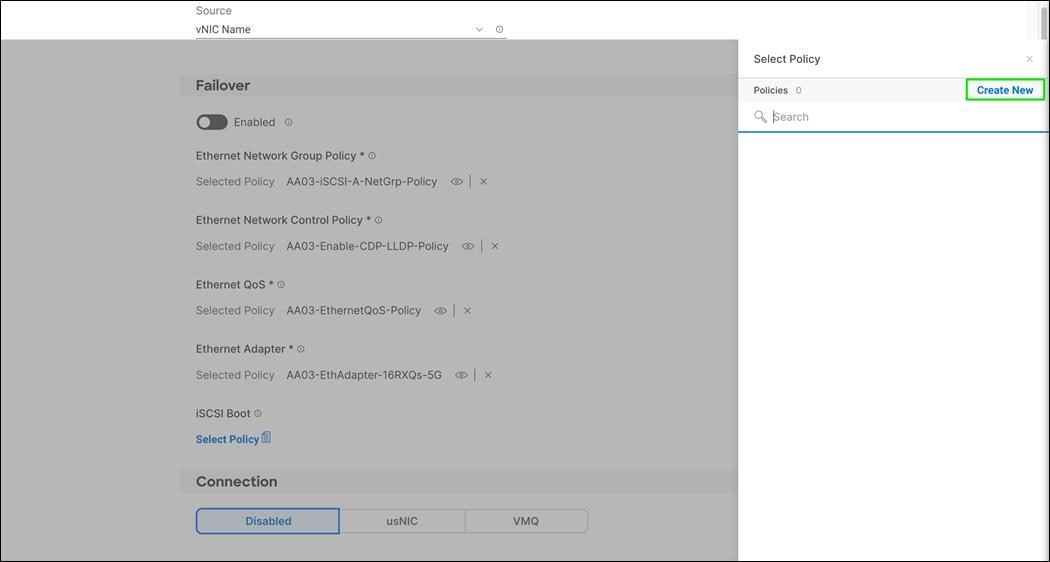
Step 3. Verify correct organization is selected from the drop-down list (for example, FlashStack) and provide a name for the policy (for example, AA03-iSCSI-A-Boot-Policy).

Step 4. Click Next.
Step 5. Select Static under Configuration.
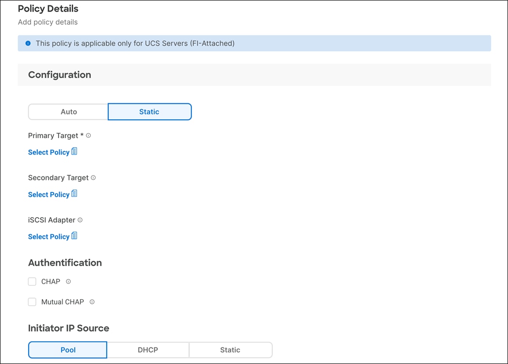
Step 6. Click Select Policy under Primary Target.
Step 7. In the pane on the right, click Create New.
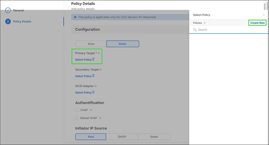
Step 8. Verify correct organization is selected from the drop-down list (for example, FlashStack) and provide a name for the policy (for example, AA03-XL-iSCSI-A-Pri-Tgt).
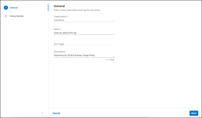
Step 9. Click Next.
Step 10. Provide the Target Name captured from Pure FlashArray, IP Address of ct0.eth4, Port 3260 and Lun ID of 1
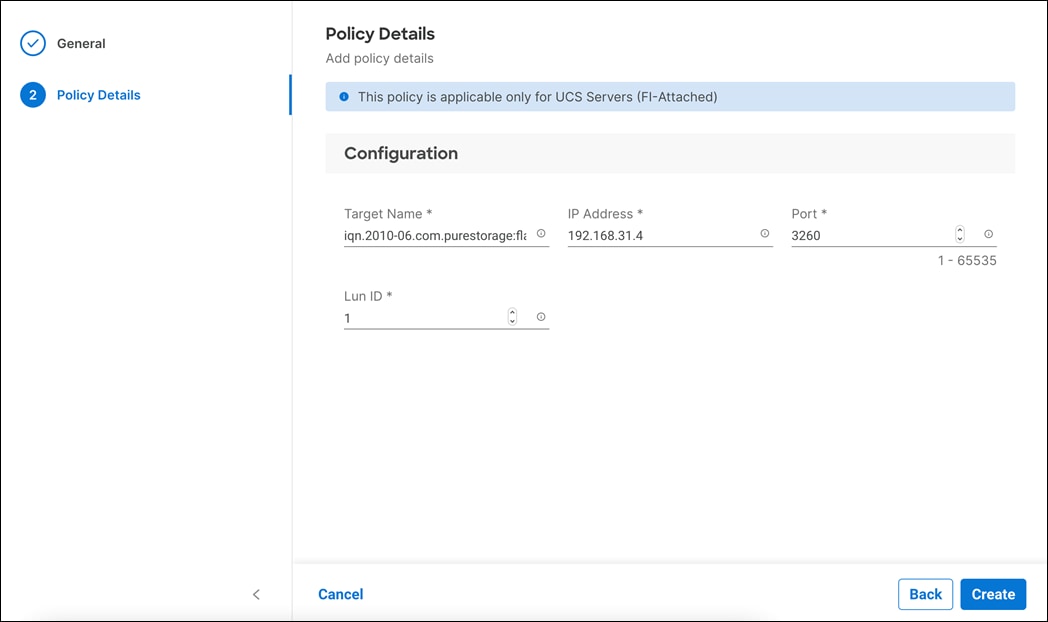
Step 11. Click Create.
Step 12. Click Select Policy under Secondary Target.
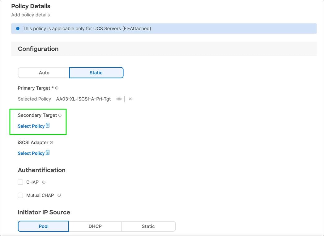
Step 13. In the pane on the right, click Create New.
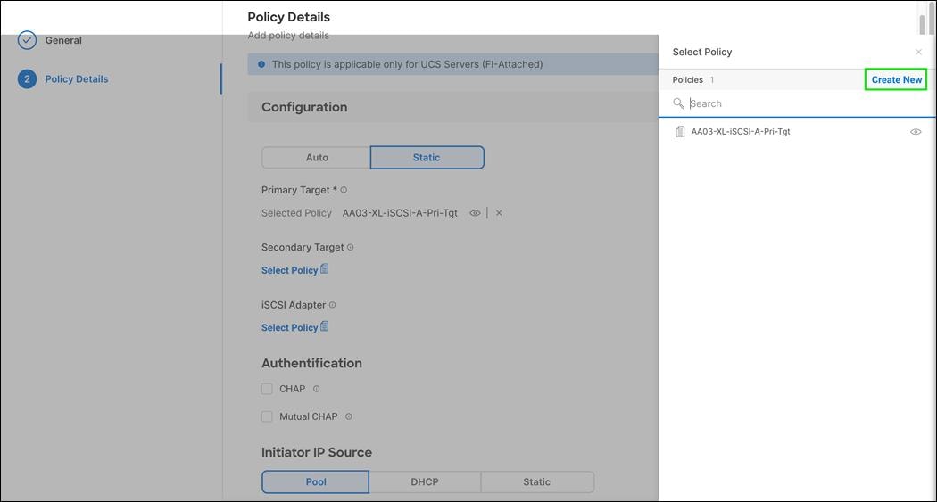
Step 14. Verify correct organization is selected from the drop-down list (for example, FlashStack) and provide a name for the policy (for example, AA03-XL-iSCSI-A-Sec-Tgt).

Step 15. Click Next.
Step 16. Provide the Target Name captured from Pure FlashArray, IP Address of ct1.eth4, Port 3260 and Lun ID of 1

Step 17. Click Create.
Step 18. Click Select Policy under iSCSI Adapter.
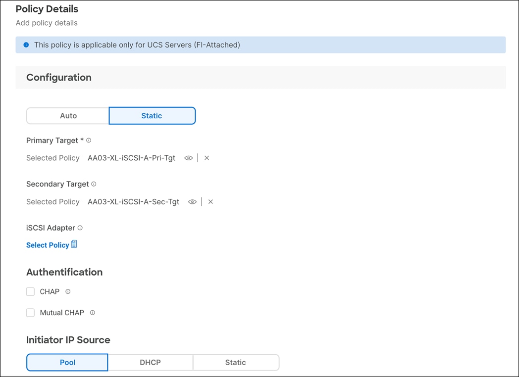
Step 19. In the pane on the right, click Create New.
Step 20. Verify correct organization is selected from the drop-down list (for example, FlashStack) and provide a name for the policy (for example, AA03-iSCSI-Adapter-Policy).

Step 21. Click Next.
Step 22. Accept the default policies. Customers can adjust the timers if necessary.
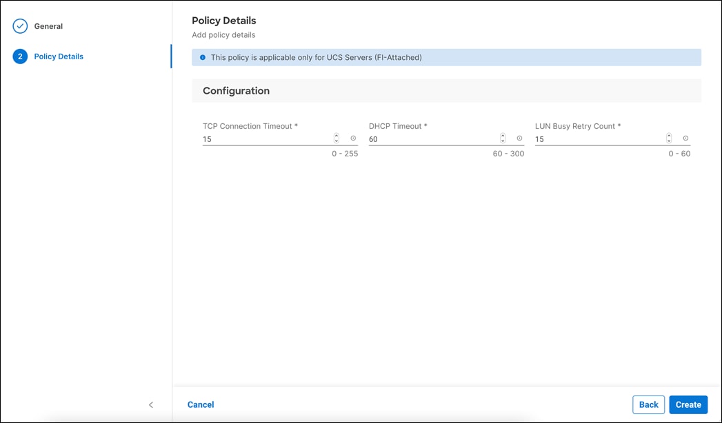
Step 23. Click Create.
Step 24. Scroll down to Initiator IP Source and make sure Pool is selected.

Step 25. Click Select Pool under IP Pool.
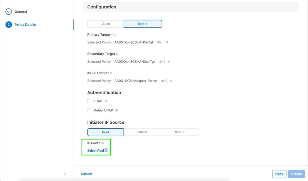
Step 26. In the pane on the right, click Create New.
Step 27. Verify correct organization is selected from the drop-down list (for example, FlashStack) and provide a name for the pool (for example, AA03-iSCSI-A-Pool).

Step 28. Click Next.
Step 29. Make sure Configure IPv4 Pool is selected.
Step 30. Enter the IP pool information for iSCSI-A subnet.
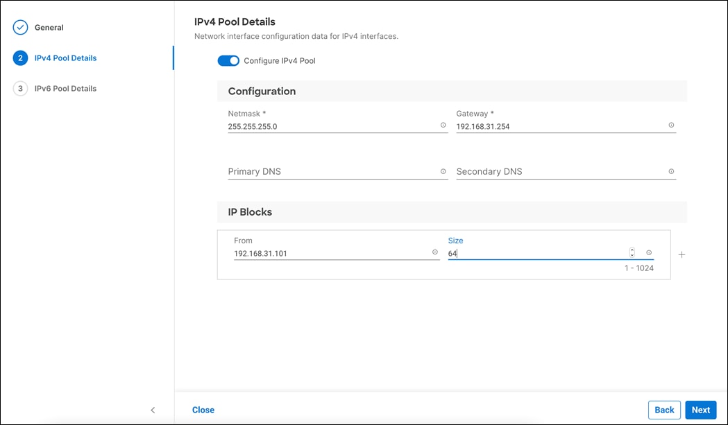
Note: Since the iSCSI network is not routable and all the VMkernel ports and LIFs are layer-2 adjacent, there is no need to define a gateway or DNS.
Step 31. Click Next.
Step 32. Disable Configure IPv6 Pool.
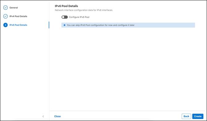
Step 33. Click Create.
Step 34. Verify all the policies and pools are correctly mapped for the iSCSI-A policy.

Step 35. Click Create.
Procedure 2. Create iSCSI-B Policy
Note: The iSCSI-B policy is only applied to vNICs 05-iSCSI-B and should not be created for data vNICs (vSwitch0 and VDS).
Step 1. Click Select Policy under iSCSI Boot.
Step 2. In the pane on the right, click Create New.
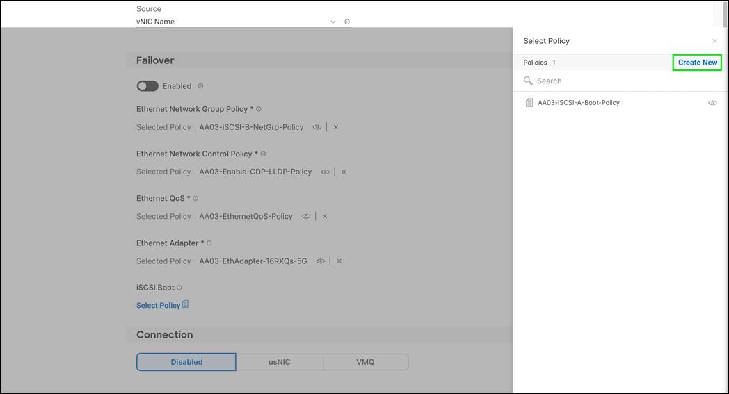
Step 3. Verify correct organization is selected from the drop-down list (for example, FlashStack) and provide a name for the policy (for example, AA03-iSCSI-B-Boot-Policy).

Step 4. Click Next.
Step 5. Select Static under Configuration.
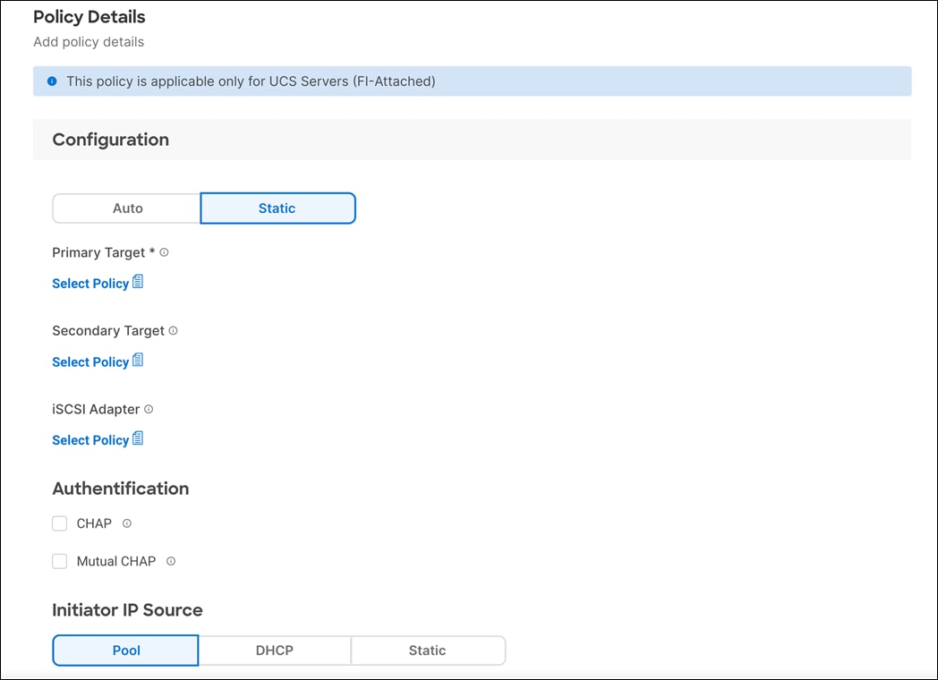
Step 6. Click Select Policy under Primary Target and then, in the pane on the right, click Create New.
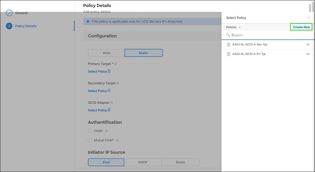
Step 7. Verify correct organization is selected from the drop-down list (for example, FlashStack) and provide a name for the policy (for example, AA03-XL-iSCSI-B-Pri-Tgt).

Step 8. Click Next.
Step 9. Provide the Target Name captured from Pure FlashArray, IP Address of ct0.eth5, Port 3260 and Lun ID of 1.
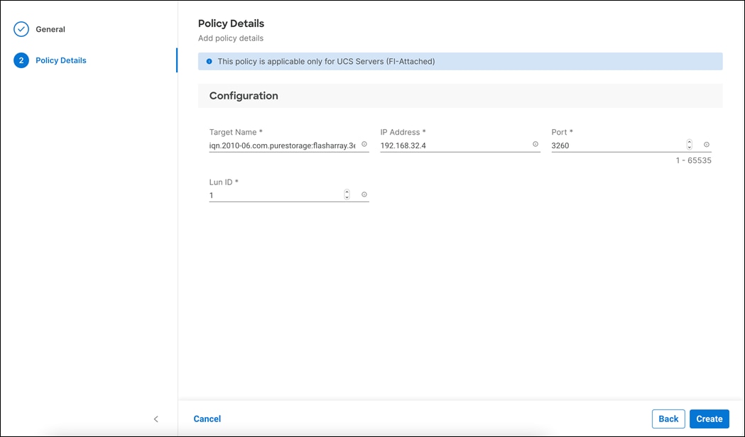
Step 10. Click Create.
Step 11. Click Select Policy under Secondary Target and then, in the pane on the right, click Create New.

Step 12. Verify correct organization is selected from the drop-down list (for example, FlashStack) and provide a name for the policy (for example, AAO3-XL-iSCSI-B-Sec-Tgt).
Step 13. Click Next.
Step 14. Provide the Target Name captured from Pure FlashArray, IP Address of ct0.eth5, Port 3260 and Lun ID of 1

Step 15. Click Create.
Step 16. Click Select Policy under iSCSI Adapter and then, in the pane on the right, select the previously configured adapter policy AAO3-iSCSI-Adapter-Policy).
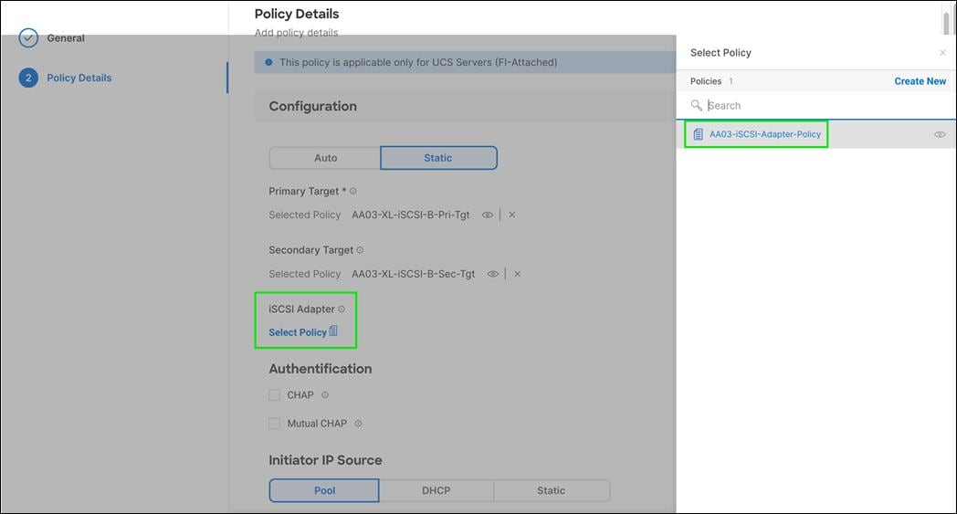
Step 17. Scroll down to Initiator IP Source and make sure Pool is selected.
Step 18. Click Select Pool under IP Pool and then, in the pane on the right, click Create New.
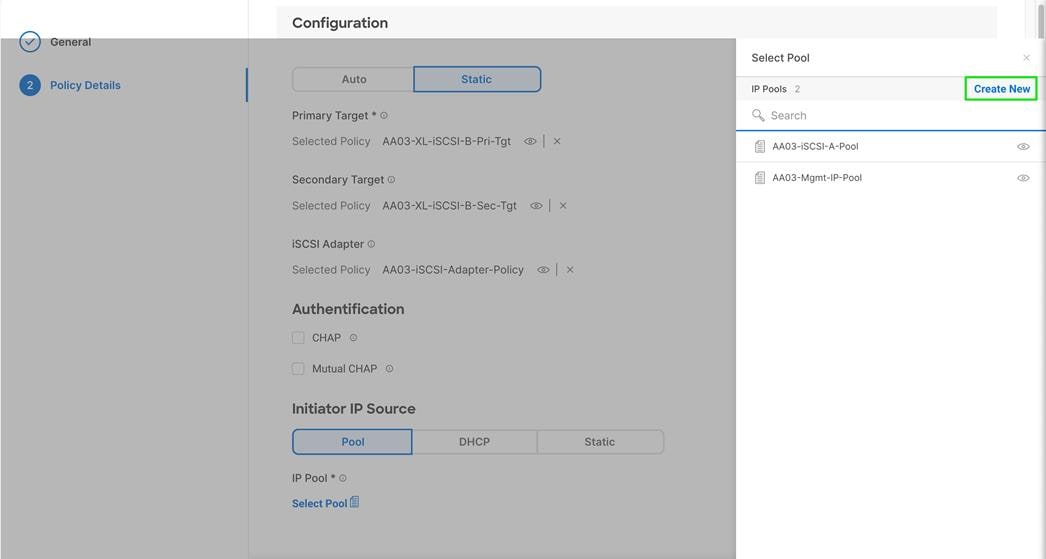
Step 19. Verify correct organization is selected from the drop-down list (for example, FlashStack) and provide a name for the pool (for example, AA03-iSCSI-B-Pool).
Step 20. Click Next.
Step 21. Make sure Configure IPv4 Pool is selected. Enter the IP pool information for iSCSI-B subnet.
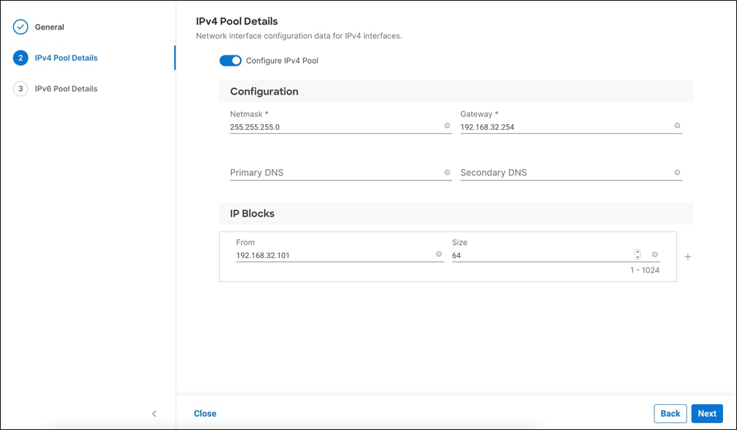
Step 22. Click Next.
Step 23. Disable Configure IPv6 Pool.
Step 24. Click Create.
Step 25. Verify all the policies and pools are correctly mapped for the iSCSI-B policy.
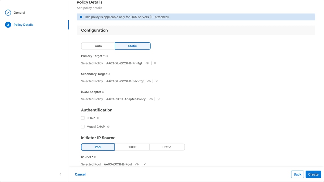
Step 26. Click Create.
Step 27. Click Create to finish creating the vNIC.
Step 28. Repeat vNIC creation for all six vNICs.
Step 29. Click Create to finish creating the LAN Connectivity policy for iSCSI hosts.
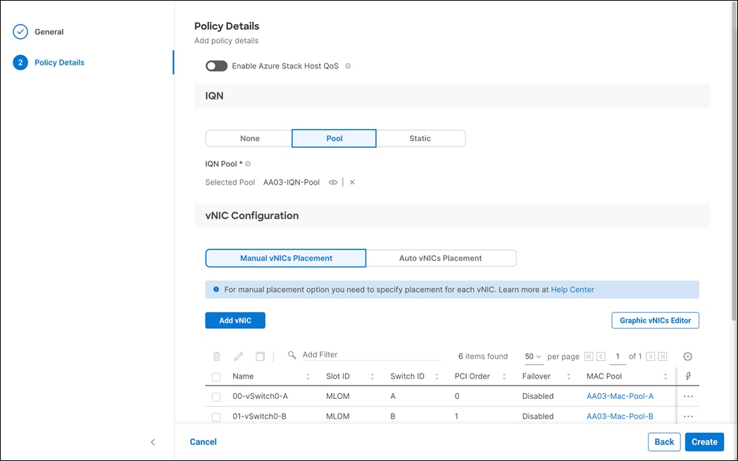
Step 30. Verify all six vNICs were created successfully.
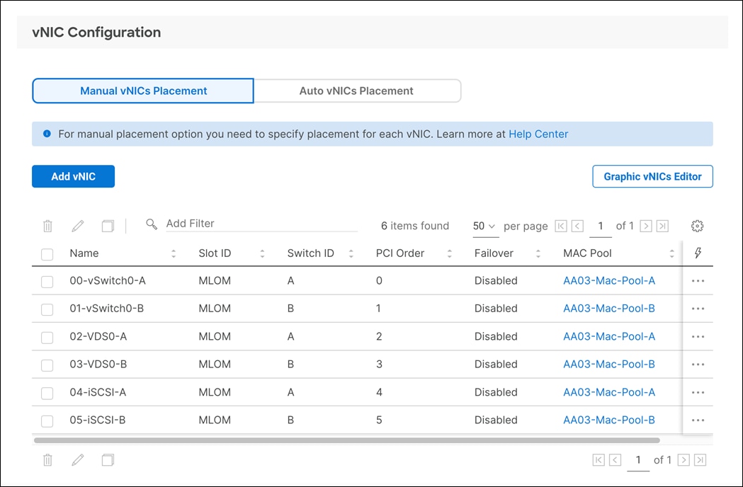
Step 31. Click Next.
Step 32. In Summary screen, click on each tab and make sure the policies are applied correct.
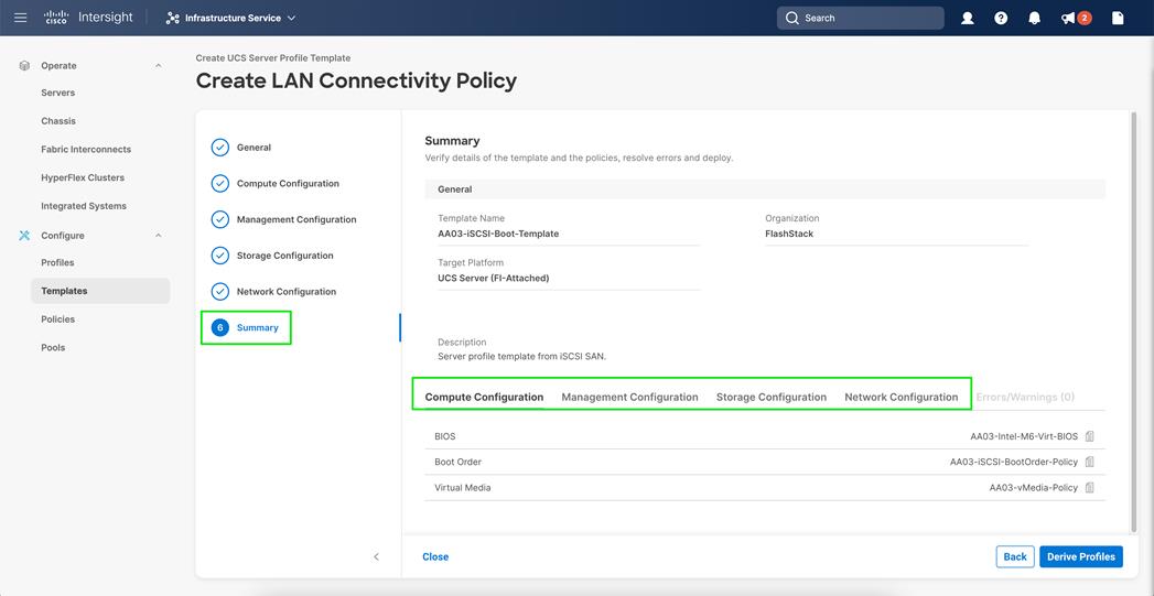
Step 33. Click Close.
LAN Connectivity Policy for FC Hosts
The FC boot from SAN hosts uses four vNICs configured as listed in Table 20.
Table 20. vNICs for FC LAN Connectivity
| vNIC/vHBA Name |
Slot ID |
Switch ID |
PCI Order |
VLANs |
| 00-vSwitch0-A |
MLOM |
A |
0 |
OOB-MGMT-VLAN IB-MGMT-VLAN |
| 01-vSwitch0-B |
MLOM |
B |
1 |
OOB-MGMT-VLAN IB-MGMT-VLAN |
| 02-VDS0-A |
MLOM |
A |
2 |
VM Traffic vMotion |
| 03-VDS0-B |
MLOM |
B |
3 |
VM Traffic vMotion |
Procedure 1. Create the LAN Connectivity Policy for FC Hosts
Step 1. Click Select Policy next to LAN Connectivity.
Step 2. In the pane on the right, click Create New.
Step 3. Verify correct organization is selected from the drop-down list (for example, FlashStack) and provide a name for the policy (for example, AA03-FC-LAN-Conn-Policy). Click Next.
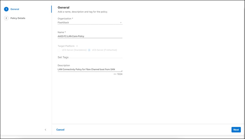
Step 4. Under IQN, select None.
Step 5. Under vNIC Configuration, select Manual vNICS Placement.
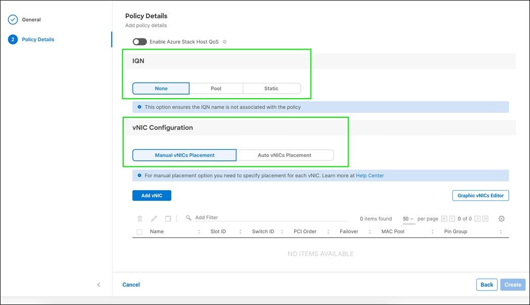
Step 6. Click on Add vNIC.
Step 7. The four vNICs created in the LAN Connectivity Policy for FC Hosts are identical to the first four vNICs in the LAN Connectivity Policy for iSCSI Hosts.
Step 8. Follow the previous procedure detailed in LAN Connectivity Policy for iSCSI Hosts section for creating the first four vNICs. (00-vSwitch0-A, 01-vSwitch0-B, 02-VDS0-A, and 03-VDS0-B excluding 04-iSCSI-A and 05-iSCSI-B).
Step 9. Verify all four vNICs were successfully created.
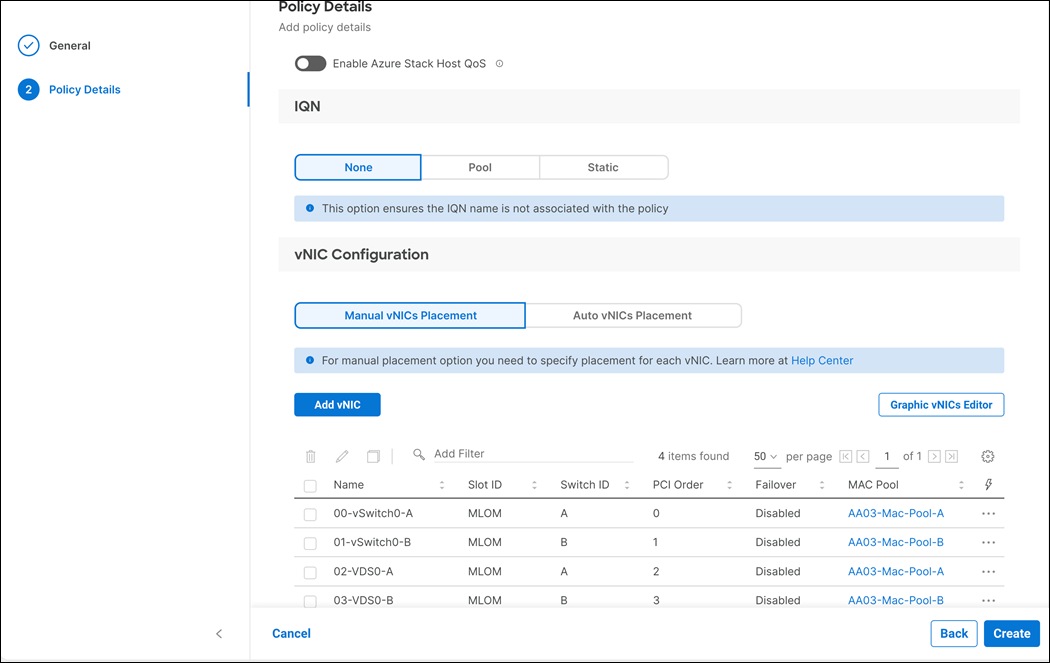
Step 10. Click Next.
Network Connectivity - SAN Connectivity Policy
Table 21 lists the details of four vHBAs. Two vHBAs are used to provide scsi-fc connectivity and boot from SAN functionality. The other two vHBAs are used to provide fc-nvme connectivity.
Table 21. vHBA for Boot from FC SAN
| vNIC/vHBA Name |
Slot |
Switch ID |
| vHBA-A |
MLOM |
A |
| vHBA-B |
MLOM |
B |
| vHBA-NVMe-A |
MLOM |
A |
| vHBA-NVMe-B |
MLOM |
B |
Procedure 1. Create SAN Connectivity Policy
Step 1. Click Select Policy next to SAN Connectivity and in the pane on the right, click Create New.
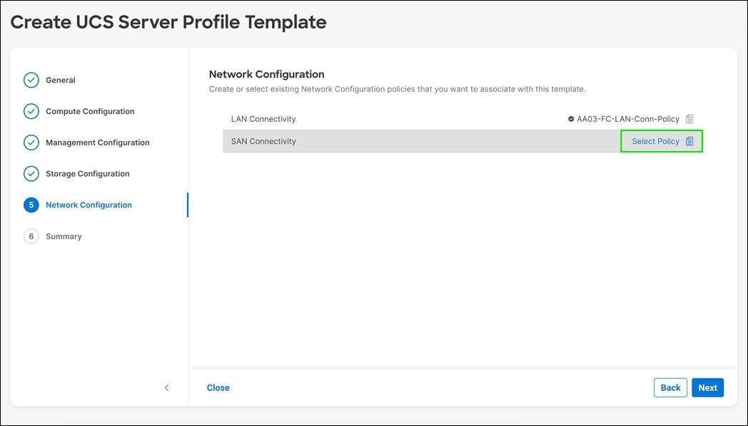
Step 2. Provide a name for the policy (for example, AA03-SAN-Conn-PoliCy).
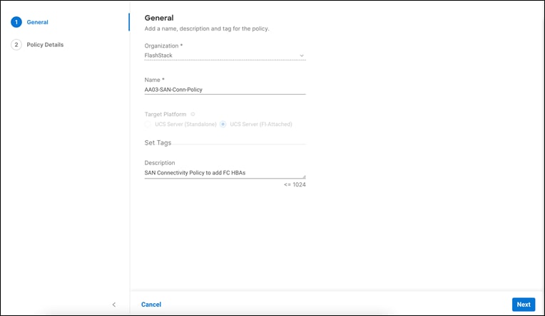
Step 3. Click Next.
Step 4. Select Manual vHBAs Placement.
Step 5. Select Pool under WWNN Address.
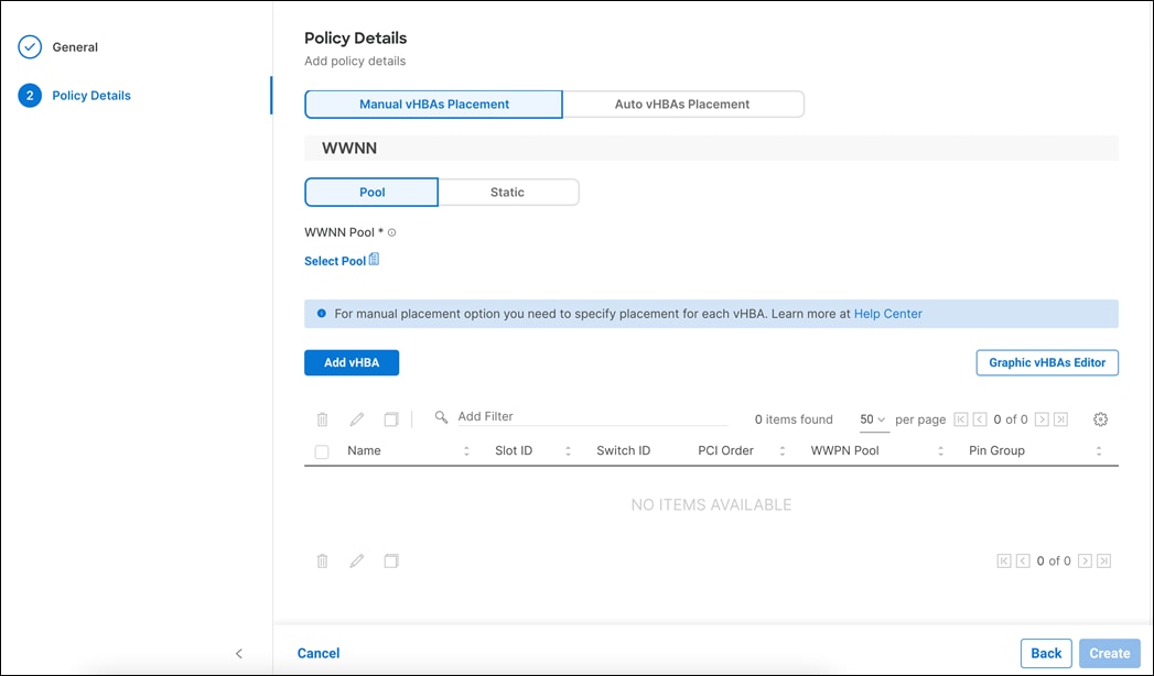
Procedure 2. Create WWNN Address Pool
Step 1. Click Select Pool under WWNN Address Pool and then, in the pane on the right, click Create New.
Step 2. Verify correct organization is selected from the drop-down list (for example, FlashStack) and provide a name for the policy (for example, AA03-WWNN-Pool).

Step 3. Click Next.
Step 4. Provide the starting WWNN block address and the size of the pool.
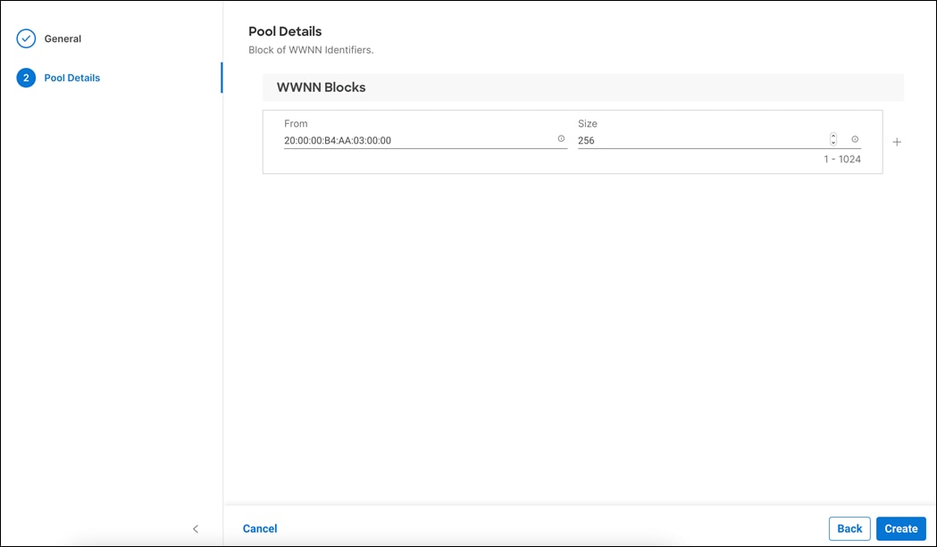
Note: As a best practice, in FlashStack some additional information is always coded into the WWNN address pool for ease of troubleshooting. For example, in the address 20:00:00:B4:AA:03:00:00, AA is the row ID, 03 is the rack ID.
Step 5. Click Create to finish creating the WWNN address pool.
Procedure 3. Create vHBA - SAN A
The Ethernet Network Control Policy is used to enable CDP and LLDP for the vNICs. A single policy will be created and reused for all the vNICs.
Step 1. Click Add vHBA.
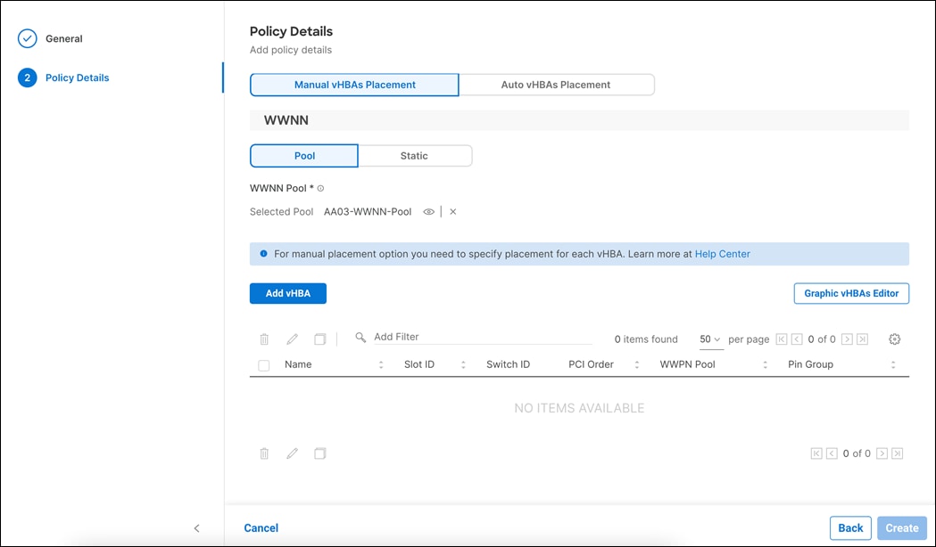
Step 2. For vHBA Type, select fc-initiator from the drop-down list.
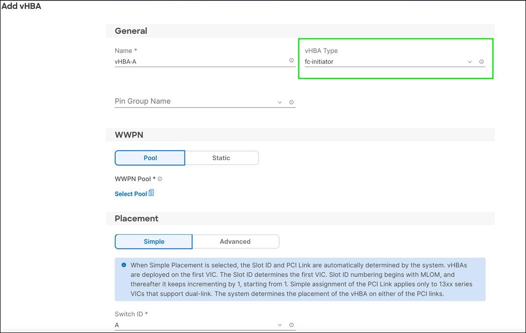
Procedure 4. Create the WWPN Pool for SAN A
Step 1. Click Select Pool under WWPN Address Pool and then, in the pane on the right, click Create New.
Step 2. Verify correct organization is selected from the drop-down list (for example, FlashStack) and provide a name for the policy (for example, AA03-WWPN-Pool-A).

Step 3. Provide the starting WWPN block address for SAN A and the size.
Note: As a best practice, in the FlashStack datacenter some additional information is always coded into the WWPN address pool for ease of troubleshooting. For example, in the address 20:00:00:B4:AA:03:0A:00, AA is the row ID, 03 is the rack ID and 0A signifies SAN A.
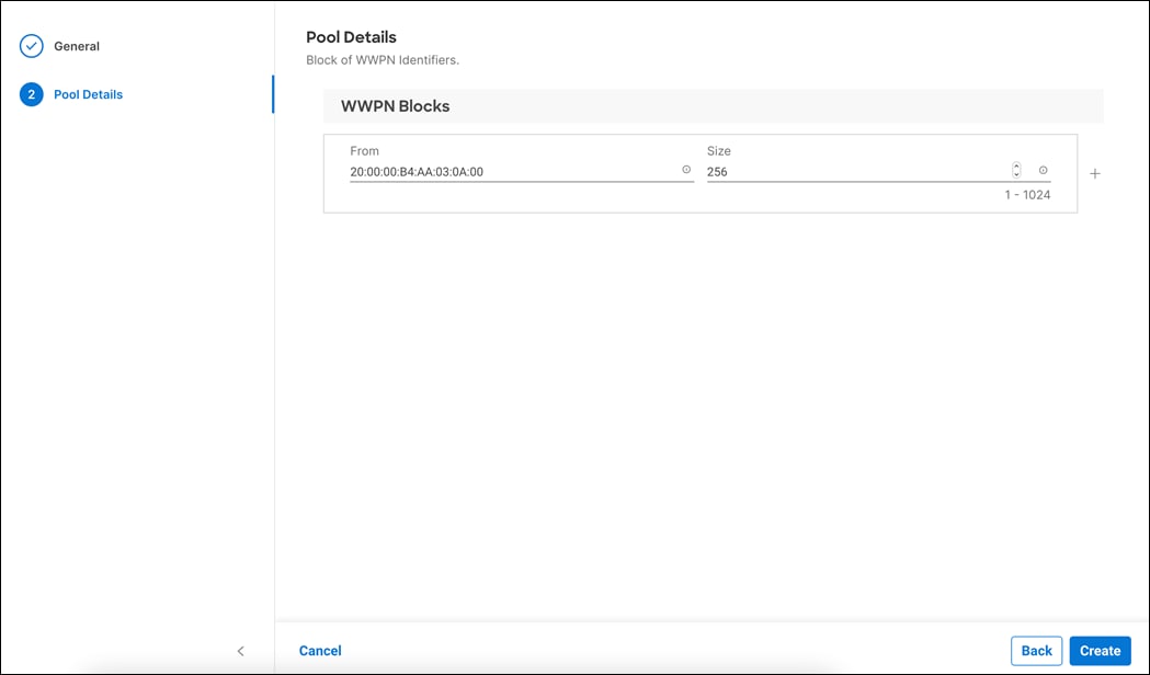
Step 4. Click Create to finish creating the WWPN pool.
Step 5. Back in the Create vHBA window, using Advanced Placement, provide the Name (for example, vHBA-A), vHBA Type, Slot ID, Switch ID (for example, A) and PCI Order.
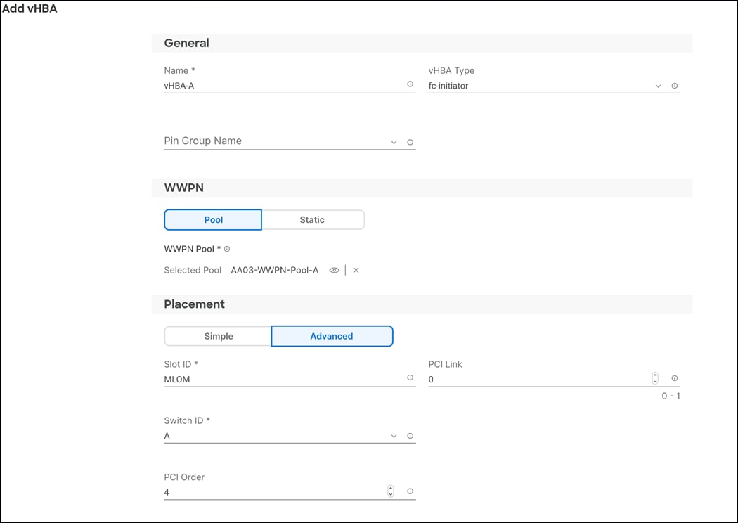
Procedure 5. Create Fibre Channel Network Policy for SAN A
A Fibre Channel network policy governs the VSAN configuration for the virtual interfaces. In this deployment, VSAN 103 will be used for vHBA-A.
Step 1. Click Select Policy Fibre Channel Network.
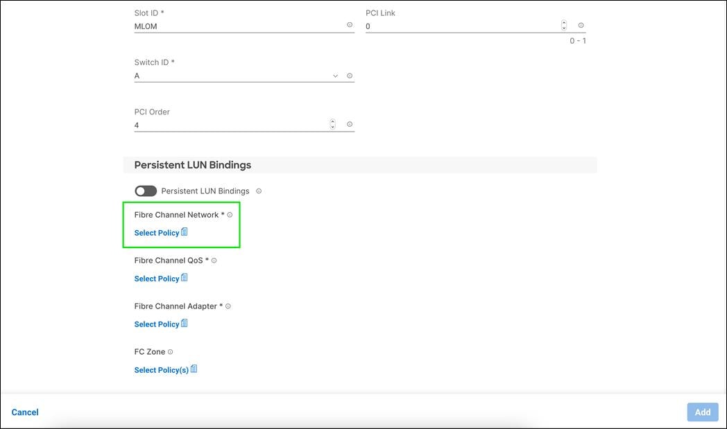
Step 2. In the pane on the right, click Create New.
Step 3. Verify correct organization is selected from the drop-down list (for example, FlashStack) and provide a name for the policy (for example, AA03-FC-Network-SAN-A).
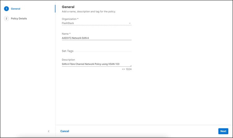
Step 4. Click Next.
Step 5. Under Default VLAN, enter the Fabric A FCoE VLAN ID (for example, 103). Under VSAN ID, provide the VSAN information (for example, 103). It is recommended to use the same value for FCoE VLAN ID and VSAN ID.
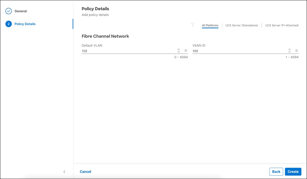
Step 6. Click Create to finish creating the Fibre Channel network policy.
Procedure 6. Create Fibre Channel QoS Policy
The Fibre Channel QoS policy assigns a system class to the outgoing traffic for a vHBA. This system class determines the quality of service for the outgoing traffic. The Fibre Channel QoS policy used in this deployment will use default values and will be shared by both vHBA-A and vHBA-B.
Step 1. Click Select Policy under Fibre Channel QoS.
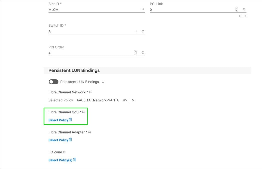
Step 2. In the pane on the right, click Create New.
Step 3. Verify correct organization is selected from the drop-down list (for example, FlashStack) and provide a name for the policy (for example, AA03-FC-QoS-Policy).

Step 4. Click Next.
Step 5. For the scope, select UCS Server (FI-Attached).
Step 6. Do not change the default values on the Policy Details screen.
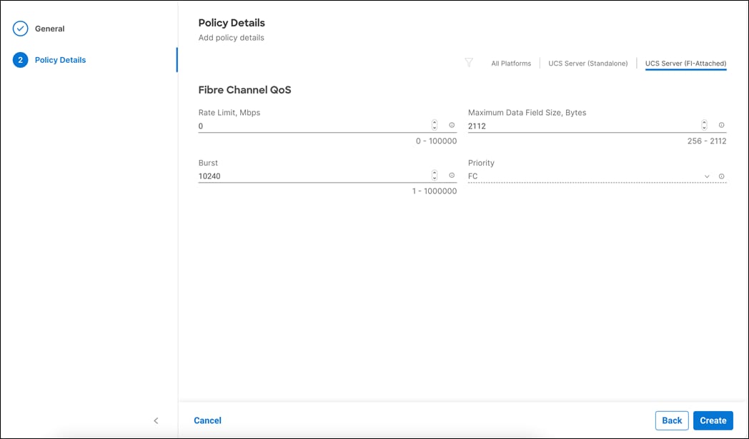
Step 7. Click Create to finish creating the Fibre Channel QoS policy.
Procedure 7. Fibre Channel Adapter Policy
A Fibre Channel adapter policy governs the host-side behavior of the adapter, including how the adapter handles traffic. In this validation, we will use the default values for the adapter policy and the policy will be shared by both vHBA-A and vHBA-B.
Step 1. Click Select Policy under Fibre Channel Adapter and in the pane on the right, click Create New.
Step 2. Verify correct organization is selected from the drop-down list (for example, FlashStack) and provide a name for the policy (for example, AA03-FC-Adapter-Policy)
Step 3. Under Fibre Channel Adapter Default Configuration, click Select Default Configuration.
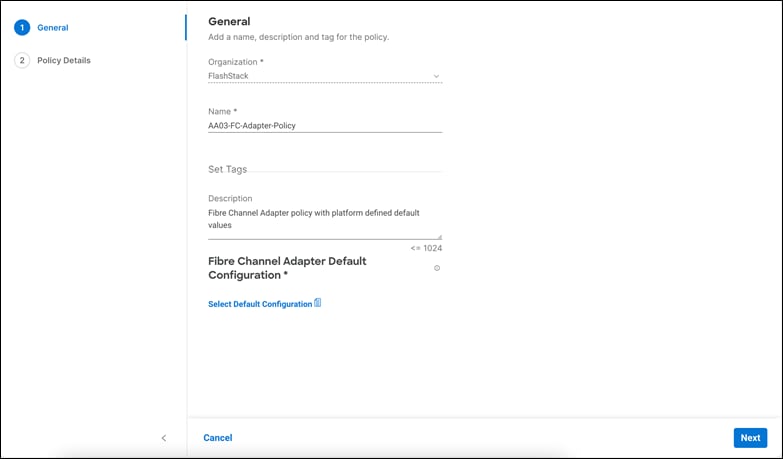
Step 4. Select VMware.
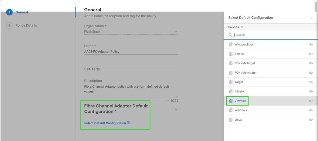
Step 5. Click Next.
Step 6. For the scope, select UCS Server (FI-Attached).
Step 7. Do not change the default values on the Policy Details screen.
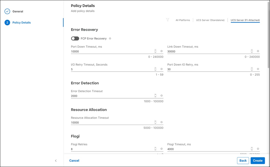
Step 8. Click Create to finish creating the Fibre Channel adapter policy.
Step 9. Click Add to create vHBA-A.
Procedure 8. Create vHBA - SAN B
Step 1. Click Add vHBA.
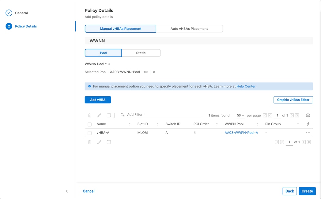
Step 2. For vHBA Type, select fc-initiator from the drop-down list.
Procedure 9. Create vHBA - SAN B
The WWPN address pool has not been defined yet therefore a WWPN address pool for Fabric B will be defined. This pool will also be used for the NVMe-FC vHBAs if the vHBAs are defined.
Step 1. Click Select Pool under WWPN Address Pool and then, in the pane on the right, click Create New.
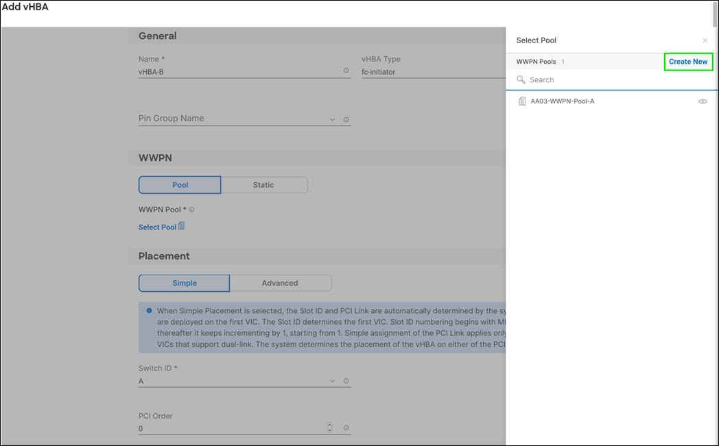
Step 2. Verify correct organization is selected from the drop-down list (for example, FlashStack) and provide a name for the policy (for example, AA03-WWPN-Pool-B).

Step 3. Click Next.
Step 4. Provide the starting WWPN block address for SAN B and the size.
Note: As a best practice, in FlashStack datacenter, some additional information is always coded into the WWPN address pool for ease of troubleshooting. For example, in the address 20:00:00:B4:AA:03:0B:00, AA is the row ID, 03 is the rack ID and 0B signifies SAN B.
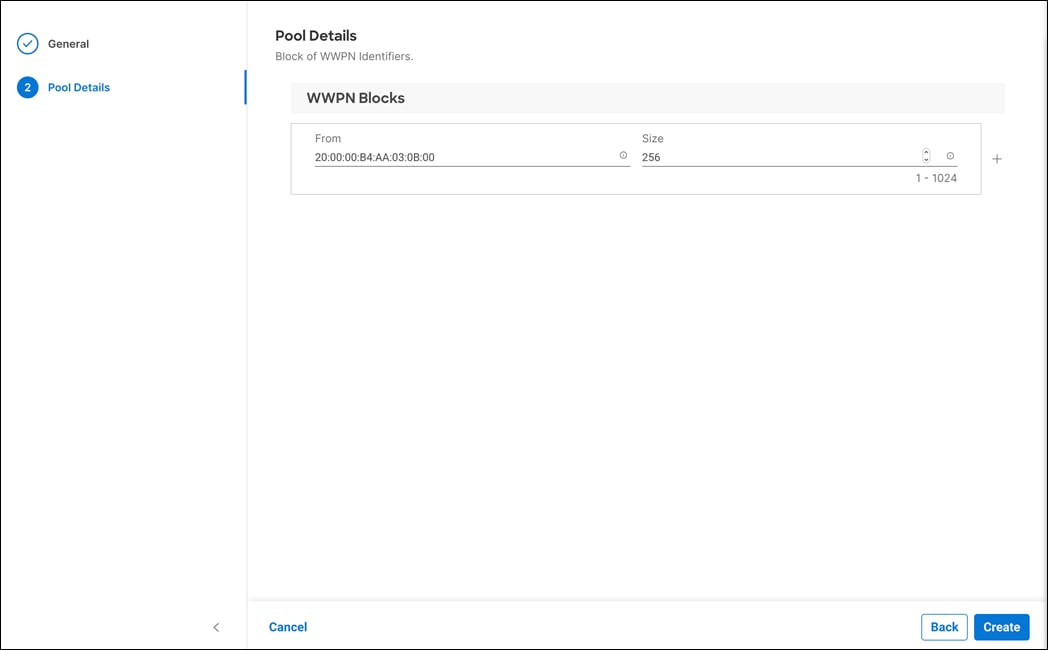
Step 5. Click Create to finish creating the WWPN pool.
Step 6. In the Create vHBA window, under Advanced Placement, provide the Name (for example, FCP-Fabric-B), Slot ID, Switch ID (for example, B) and PCI Order.
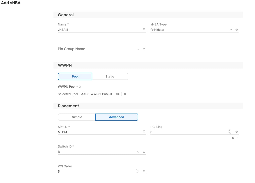
Procedure 10. Create Fibre Channel Network Policy for SAN B
Note: In this deployment, VSAN 104 is used for vHBA FCP-Fabric-B.
Step 1. Click Select Policy under Fibre Channel Network and then, in the pane on the right, click Create New.
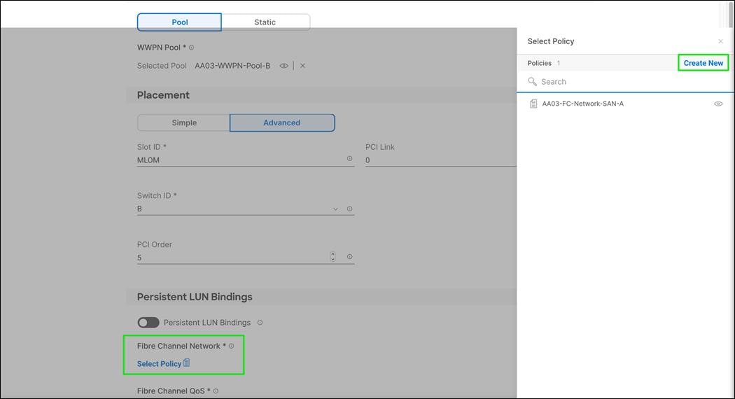
Step 2. Verify correct organization is selected from the drop-down list (for example, FlashStack) and provide a name for the policy (for example, AA03-FC-Network-SAN-B).
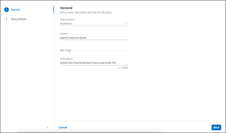
Step 3. Under Default VLAN, enter the FCoE VLAN ID (for example, 104). Under VSAN ID, provide the VSAN information (for example, 104).
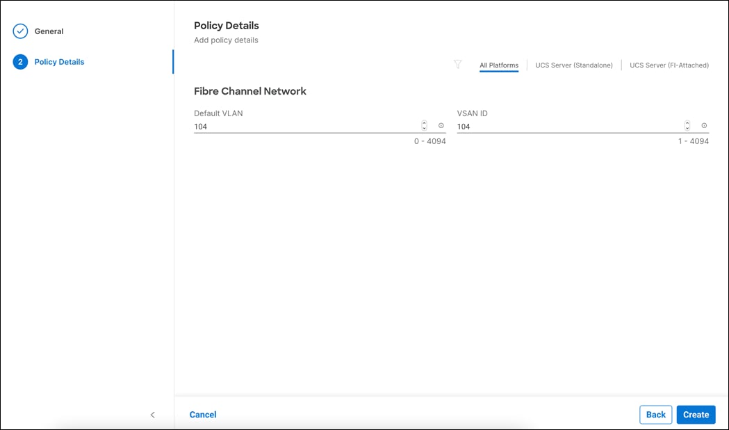
Step 4. Click Create.
Step 5. Click Select Policy under Fibre Channel QoS and then, in the pane on the right, select the previously created QoS policy AA03-FC-QoS-Policy.
Step 6. Click Select Policy under Fibre Channel Adapter and then, in the pane on the right, select the previously created Adapter policy AA03-FC-Adapter-Policy.
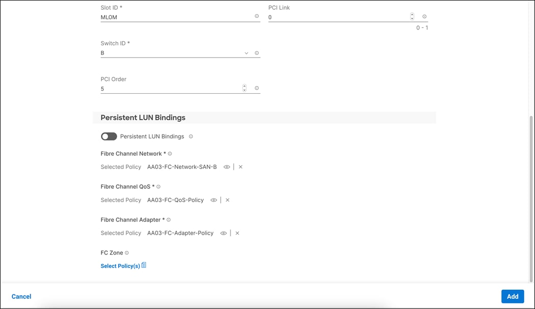
Step 7. Click Add to add the vHBA vHBA-B.
Step 8. Verify both the vHBAs are added to the SAN connectivity policy.
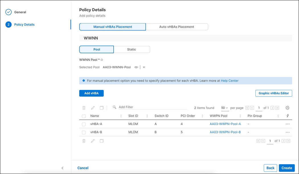
Note: If you don’t need the FC-NVMe connectivity, skip the next sections for creating FC-NVMe vHBAs.
Create the FC-NVMe vHBAs
Note: To configure FC-NVMe, two vHBAs, one for each fabric, need to be added to the server profile template. These vHBAs are in addition to the FC boot from SAN vHBA - vHBA-A and vHBA-B.
Procedure 1. Create vHBA (vHBA-NVMe-A) - SAN A
Step 1. Click Add vHBA.
Step 2. Name the vHBA vHBA-NVMe-A. For vHBA Type, select fc-nvme-initiator from the drop-down list.
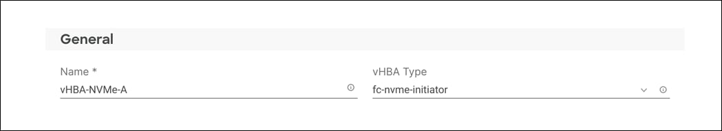
Step 3. Click Select Pool under WWPN Address Pool and then, in the pane on the right, select the previously created pool AA03-WWPN-Pool-A.
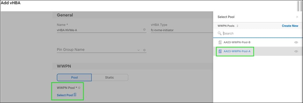
Step 4. Click Add to add the vHBA vHBA-B.
Step 5. Verify both the vHBAs are added to the SAN connectivity policy
Step 6. Under Advanced Placement, provide the Slot ID, Switch ID (for example, A) and PCI Order.
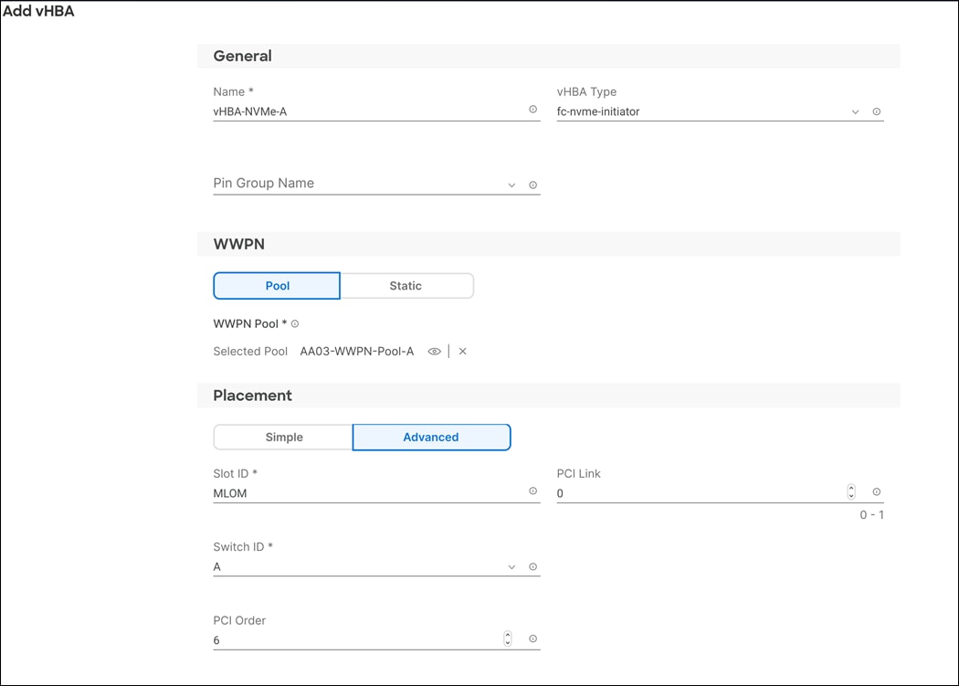
Step 7. Click Select Policy under Fibre Channel Network and then, in the pane on the right, select the previously created policy for SAN A, AA03-FC-Network-SAN-A.
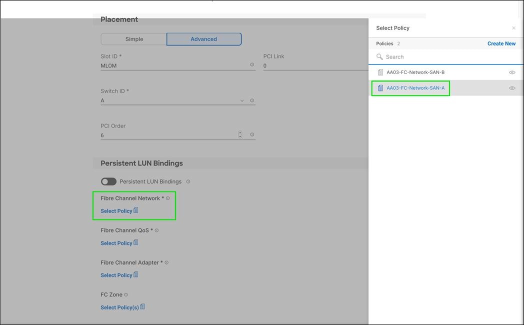
Step 8. Click Select Policy under Fibre Channel QoS and then, in the pane on the right, select the previously created QoS policy AA03-FC-QoS-Policy.
Procedure 2. Create FCNVMeInitiator Fibre Channel Adapter Policy
A Fibre Channel adapter policy governs the host-side behavior of the adapter, including the way that the adapter handles traffic. The FCNVMeInitiator Fibre Channel Adapter Policy is optimized for FC-NVMe.
Step 1. Click Select Policy under Fibre Channel Adapter and then, in the pane on the right, click Create New.
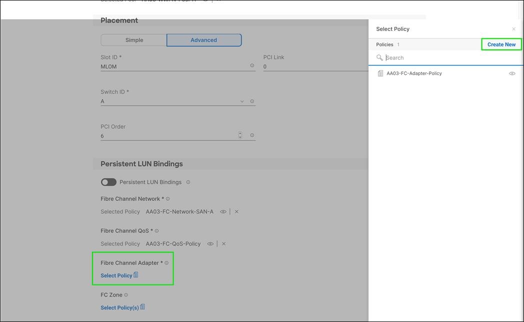
Step 2. Verify the correct organization is selected from the drop-down list (for example, FlashStack) and provide a name for the policy (for example, AA03-FC-NVMe-Initiator-Adapter-Policy).
Step 3. Under Fibre Channel Adapter Default Configuration, click Select Default Configuration.
Step 4. Select FCNVMelnitiator.
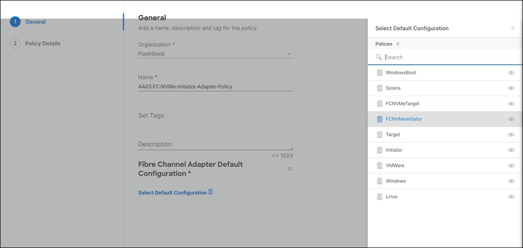
Step 5. Click Next.
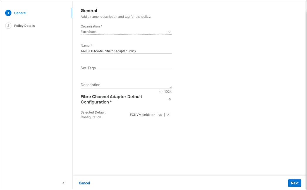
Step 6. For the scope, select UCS Server (FI-Attached).
Step 7. Do not change the default values on the Policy Details screen.

Step 8. Click Create to finish creating the Fibre Channel adapter policy.
Step 9. Verify all the vHBA policies are mapped.
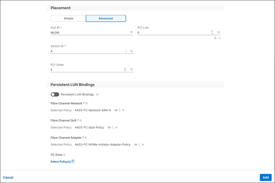
Step 10. Click Add to create vHBA FC-NVMe-Fabric-A.
Procedure 3. Create vHBA (vHBA-NVMe-B) - SAN B
Step 1. Click Add vHBA.
Step 2. Name the vHBA VHBA-NVMe-B. For vHBA Type, select fc-nvme-initiator from the drop-down list.
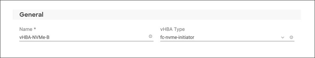
Step 3. Click Select Pool under WWPN Address Pool and then, in the pane on the right, select the previously created pool AA03-WWPN-Pool-B.
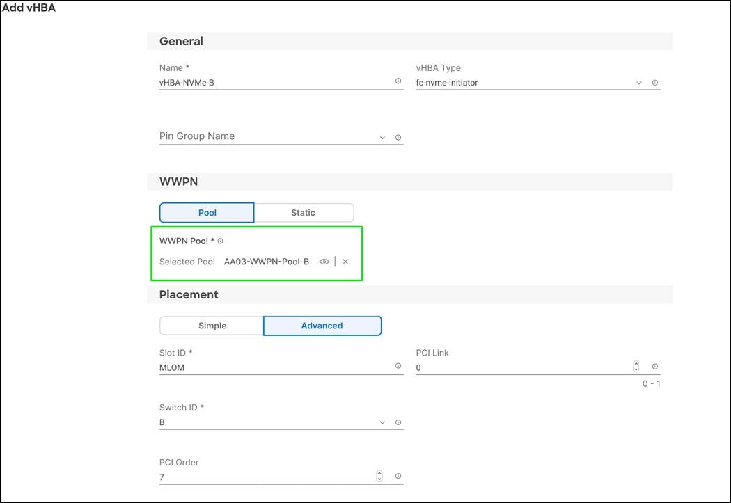
Step 4. Under Advanced Placement, provide the slot ID, Switch ID (for example, B) and PCI Order.
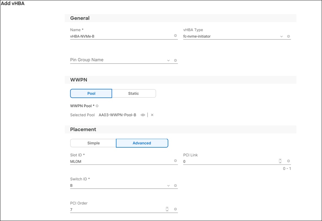
Step 5. Click Select Policy under Fibre Channel Network and then, in the pane on the right, select the previously created policy for SAN B, AA03-FC-Network-SAN-B.
Step 6. Click Select Policy under Fibre Channel QoS and then, in the pane on the right, select the previously created QoS policy AA03-FC-QoS-Policy.
Step 7. Click Select Policy under Fibre Channel Adapter and then, in the pane on the right, select the previously created Adapter policy AA03-FC-NVMe-Initiator-Adapter-Policy.
Step 8. Verify all the vHBA policies are mapped correctly.

Step 9. Click Create to create the SAN connectivity policy with NVMe-FC support.
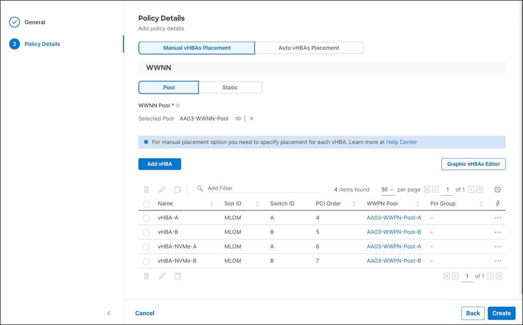
Procedure 4. Summary
Step 1. When the LAN connectivity policy and SAN connectivity policy (for FC) is created, click Next to move to the Summary screen.
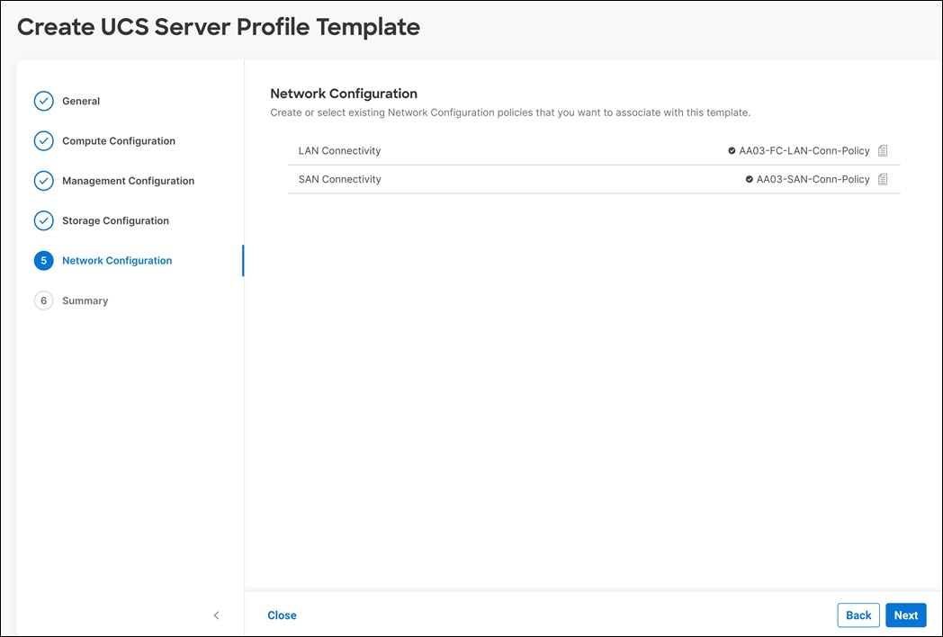
Step 2. On the summary screen, verify the policies are mapped to various settings. The screenshots below provide summary view for a Fibre Channel boot from SAN server profile template. An iSCSI boot from SAN server profile template would have a different Boot Order Policy, a different LAN Connectivity Policy, without a SAN Connectivity Policy.
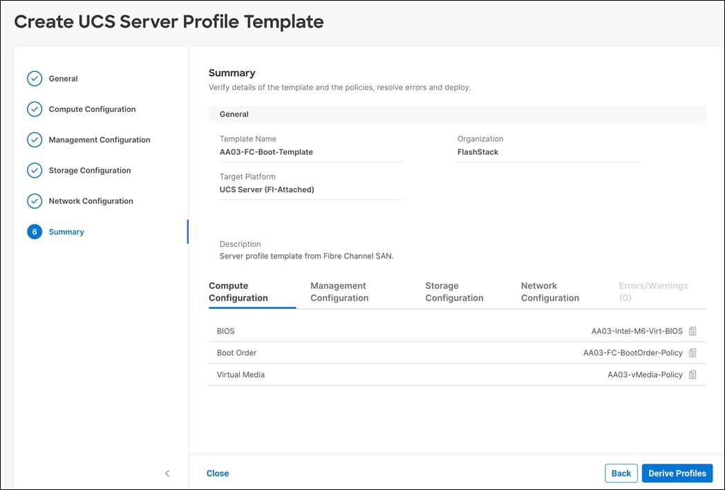
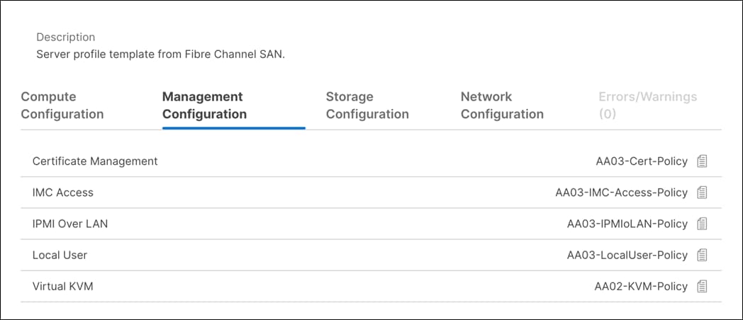
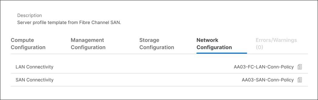
After the Cisco UCS server profiles have been created, each infrastructure server in the environment will have a unique configuration. To proceed with the FlashStack deployment, specific information must be gathered from each Cisco UCS server and from the Pure FlashArray controllers.
Table 22.WWPNs from Pure FlashArray//XL 170 Storage
| FlashArray |
Adapter |
MDS Switch |
Target: WWPN |
| aa03-fa-xl170-flashstack.com |
CT0.FC4 (scsi-fc) |
Fabric A |
<CT0.FC5-wwpn> |
| CT0.FC5 (scsi-fc) |
Fabric B |
<CT0.FC5-wwpn> |
|
| CT1.FC4 (scsi-fc) |
Fabric A |
<CT1.FC4-wwpn> |
|
| CT1.FC5 (scsi-fc) |
Fabric B |
<CT1.FC5-wwpn> |
|
|
|
CT0.FC6 (nvme-fc) |
Fabric A |
<CT0.FC6-wwpn> |
|
|
CT0.FC7 (nvme-fc) |
Fabric B |
<CT0.FC7-wwpn> |
|
|
CT1.FC6 (nvme-fc) |
Fabric A |
<CT1.FC6-wwpn> |
|
|
CT1.FC7 (nvme-fc) |
Fabric B |
<CT1.FC7-wwpn> |
Table 23.WWPNs for Cisco UCS Service Profiles
| Cisco UCS Service Profile Name |
MDS Switch |
Initiator WWPN |
| VM-Host-Infra-FCP-01 |
Fabric A |
<vm-host-infra-fcp-01-wwpna> |
| Fabric B |
<vm-host-infra-fcp-01-wwpnb> |
|
| VM-Host-Infra-FCP-02 |
Fabric A |
<vm-host-infra-fcp-02-wwpna> |
| Fabric B |
<vm-host-infra-fcp-02-wwpnb> |
|
| VM-Host-Infra-FCP-03 |
Fabric A |
<vm-host-infra-fcp-03-wwpna> |
| Fabric B |
<vm-host-infra-fcp-03-wwpnb> |
Note: To obtain the FC vHBA WWPN information in Cisco Intersight. Log into Intersight Portal. Go to CONFIGURE > Profiles and select the Server Profiles just deployed.
Cisco UCS IMM Setup Completion
Complete the following procedures whether performing an Ansible configuration or a Manual configuration of the FlashStack datacenter.
Procedure 1. Derive Server Profiles
Step 1. Open a browser to Cisco Intersight, https://intersight.com.
Step 2. Log into Cisco Intersight portal.
Step 3. From Service Selector, select Infrastructure Service.
Step 4. From the left navigation pane, select Configure > Templates.
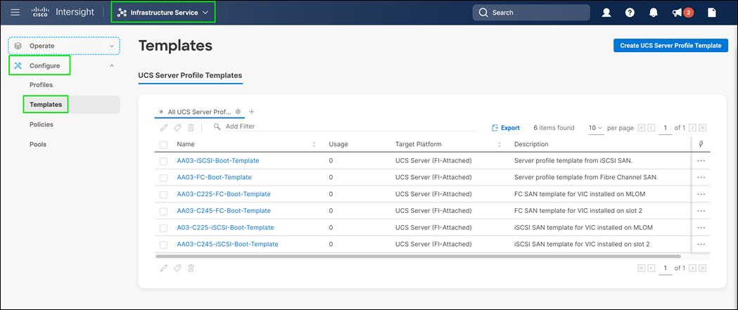
Step 5. From row actions, select Derive Profiles.
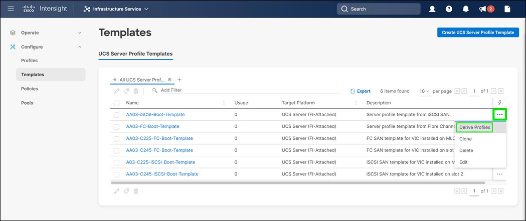
Step 6. Under the Server Assignment, select Assign Now and select Cisco UCS X210c M6 server(s). Customers can select one or more servers depending on the number of profiles to be deployed.
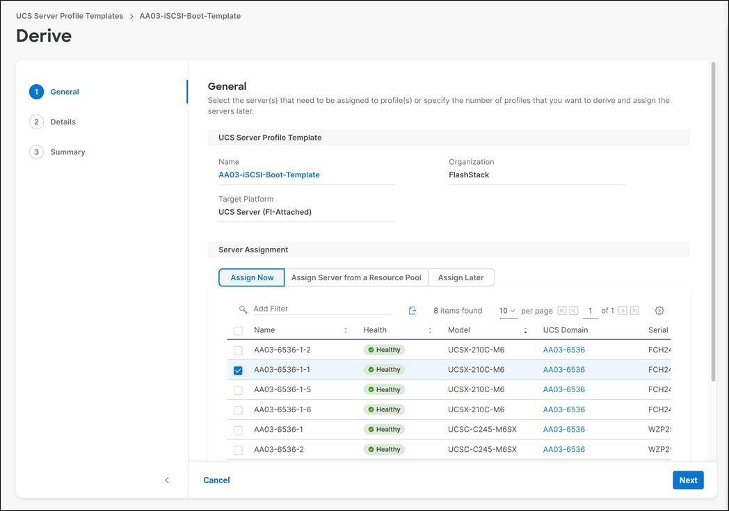
Step 7. Click Next.
Step 8. Cisco Intersight will fill in default information for the number of servers selected (1 in this case).
Step 9. Adjust the fields as needed. It is recommended to use the server hostname for the Server Profile name.
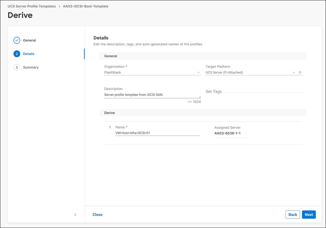
Step 10. Click Next.
Step 11. Verify the information and click Derive to create the Server Profile(s).
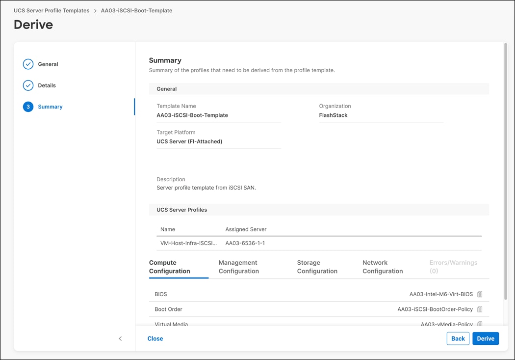
Step 12. Navigate to Infrastructure Service > Configure > Profiles > UCS Server Profiles.
Step 13. 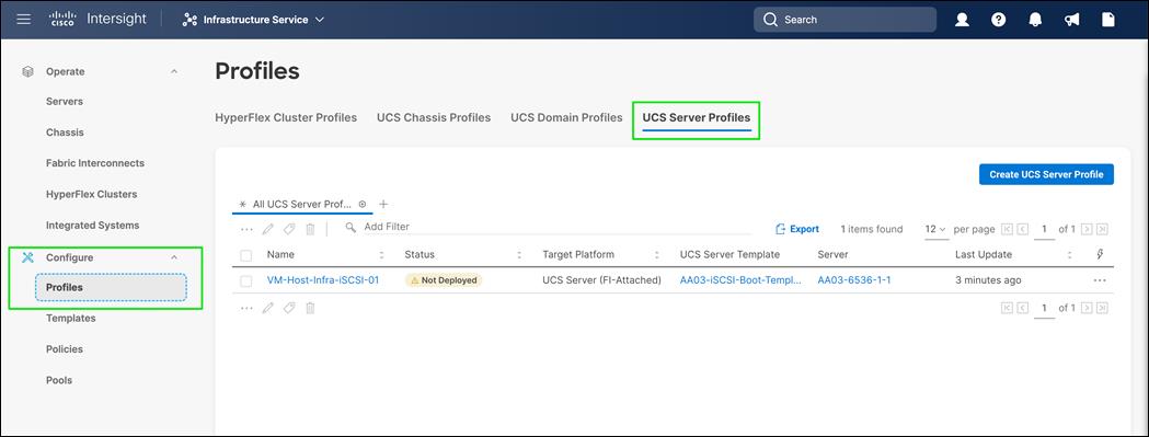
Step 14. Select the profile(s) just created. From row actions, select Deploy.
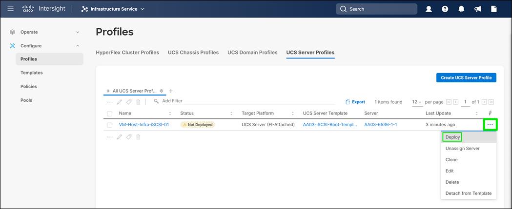
Step 15. Click Deploy to confirm.
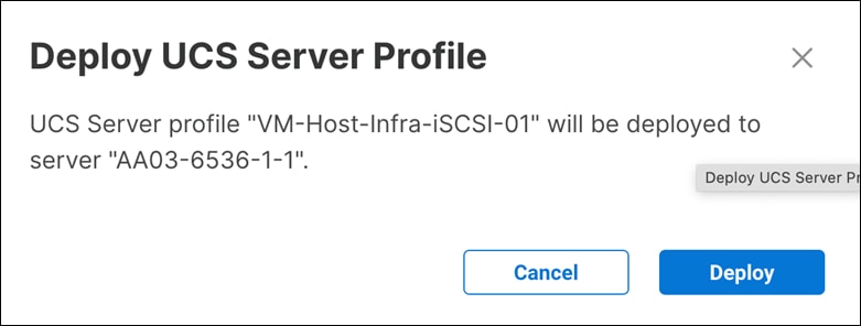
Step 16. Cisco Intersight will start deploying the server profile(s) and will take some time to apply all the policies. Use the Requests tab at the top right-hand corner of the window to see the progress.
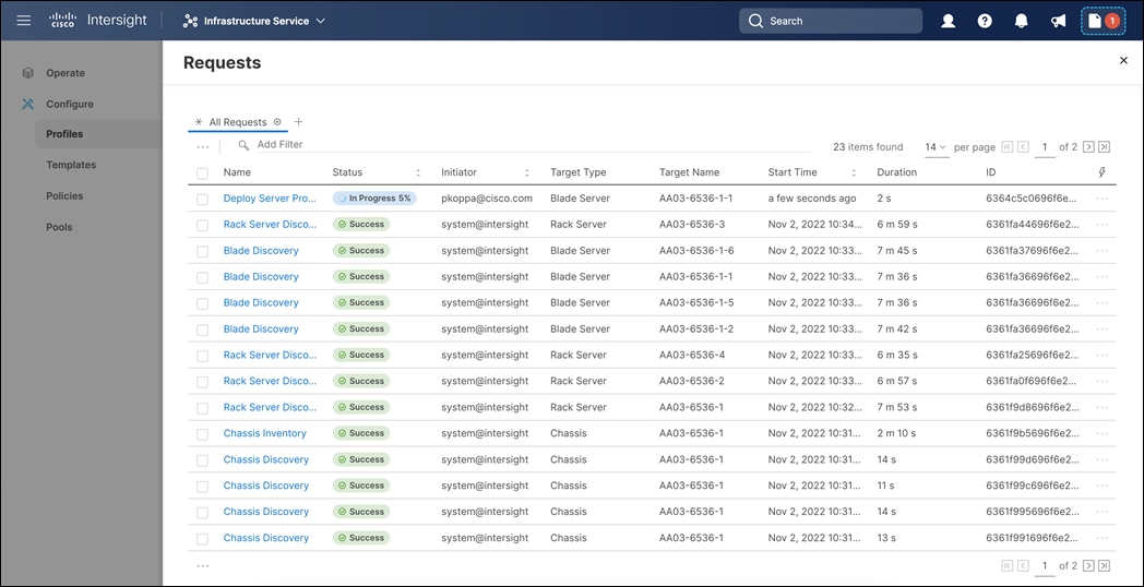
Step 17. Click on the request to view more details.
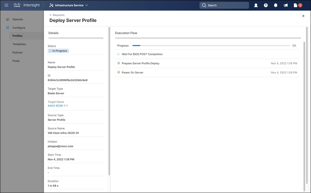
Step 18. Wait for all the tasks to complete.
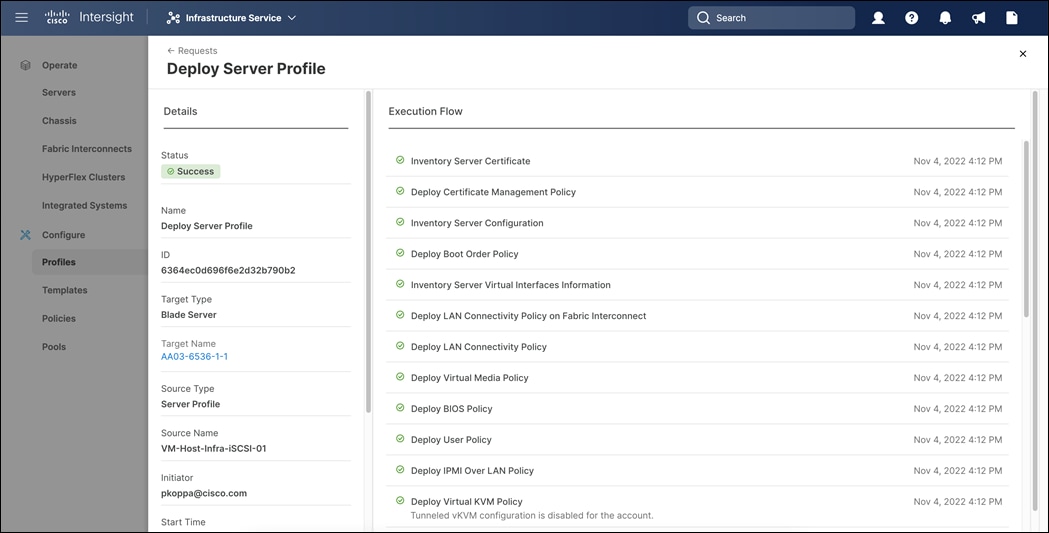
When the Server Profile(s) are deployed successfully, they will appear under the Server Profiles with the status of OK.
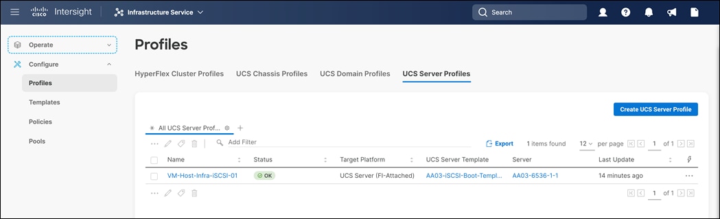
Fibre Channel SAN Configuration
This section explains how to configure the Cisco MDS 9000s for use in a FlashStack environment. The configuration explained in this section is not required for iSCSI SAN.
Note: Follow the steps precisely because failure to do so could result in an improper configuration.
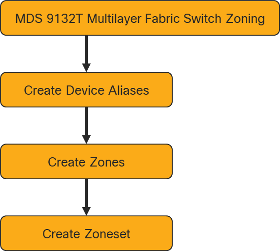
Note: If directly connecting storage to the Cisco UCS fabric interconnects, skip this section.
Physical Connectivity
Follow the physical connectivity guidelines for FlashStack as explained in section FlashStack Cabling.
FlashStack Cisco MDS Base
The following procedures describe how to configure the Cisco Nexus switches for use in a base FlashStack environment. This procedure assumes you are using the Cisco MDS 9132T with NX-OS 9.2(2).
Procedure 1. Configure Cisco MDS 9132T A <mds-A-hostname>
On initial boot and connection to the serial or console port of the switch, the NX-OS setup should automatically start and attempt to enter Power on Auto Provisioning. Enter y to get to the System Admin Account Setup.
Step 1. Configure the switch using the command line.
---- System Admin Account Setup ----
Do you want to enforce secure password standard (yes/no) [y]: Enter
Enter the password for "admin": <password>
Confirm the password for "admin": <password>
Would you like to enter the basic configuration dialog (yes/no): yes
Create another login account (yes/no) [n]: Enter
Configure read-only SNMP community string (yes/no) [n]: Enter
Configure read-write SNMP community string (yes/no) [n]: Enter
Enter the switch name : <mds-A-hostname>
Continue with Out-of-band (mgmt0) management configuration? (yes/no) [y]: Enter
Mgmt0 IPv4 address : <mds-A-mgmt0-ip>
Mgmt0 IPv4 netmask : <mds-A-mgmt0-netmask>
Configure the default gateway? (yes/no) [y]: Enter
IPv4 address of the default gateway : <mds-A-mgmt0-gw>
Configure advanced IP options? (yes/no) [n]: Enter
Enable the ssh service? (yes/no) [y]: Enter
Type of ssh key you would like to generate (dsa/rsa) [rsa]: Enter
Number of rsa key bits <1024-2048> [1024]: Enter
Enable the telnet service? (yes/no) [n]: Enter
Configure congestion/no_credit drop for fc interfaces? (yes/no) [y]: Enter
Enter the type of drop to configure congestion/no_credit drop? (con/no) [c]: Enter
Enter milliseconds in multiples of 10 for congestion-drop for logical-type edge
in range (<200-500>/default), where default is 500. [d]: Enter
Enable the http-server? (yes/no) [y]: Enter
Configure clock? (yes/no) [n]: Enter
Configure timezone? (yes/no) [n]: Enter
Configure summertime? (yes/no) [n]: Enter
Configure the ntp server? (yes/no) [n]: yes
NTP server IPv4 address : <nexus-A-mgmt0-ip>
Configure default switchport interface state (shut/noshut) [shut]: Enter
Configure default switchport trunk mode (on/off/auto) [on]: auto
Configure default switchport port mode F (yes/no) [n]: yes
Configure default zone policy (permit/deny) [deny]: Enter
Enable full zoneset distribution? (yes/no) [n]: Enter
Configure default zone mode (basic/enhanced) [basic]: Enter
Step 2. Review the configuration.
Would you like to edit the configuration? (yes/no) [n]: Enter
Use this configuration and save it? (yes/no) [y]: Enter
Procedure 2. Configure Cisco MDS 9132T B <mds-B-hostname>
On initial boot and connection to the serial or console port of the switch, the NX-OS setup should automatically start and attempt to enter Power on Auto Provisioning. Enter y to get to the System Admin Account Setup.
Step 1. Configure the switch using the command line.
---- System Admin Account Setup ----
Do you want to enforce secure password standard (yes/no) [y]: Enter
Enter the password for "admin": <password>
Confirm the password for "admin": <password>
Would you like to enter the basic configuration dialog (yes/no): yes
Create another login account (yes/no) [n]: Enter
Configure read-only SNMP community string (yes/no) [n]: Enter
Configure read-write SNMP community string (yes/no) [n]: Enter
Enter the switch name : <mds-B-hostname>
Continue with Out-of-band (mgmt0) management configuration? (yes/no) [y]: Enter
Mgmt0 IPv4 address : <mds-B-mgmt0-ip>
Mgmt0 IPv4 netmask : <mds-B-mgmt0-netmask>
Configure the default gateway? (yes/no) [y]: Enter
IPv4 address of the default gateway : <mds-B-mgmt0-gw>
Configure advanced IP options? (yes/no) [n]: Enter
Enable the ssh service? (yes/no) [y]: Enter
Type of ssh key you would like to generate (dsa/rsa) [rsa]: Enter
Number of rsa key bits <1024-2048> [1024]: Enter
Enable the telnet service? (yes/no) [n]: Enter
Configure congestion/no_credit drop for fc interfaces? (yes/no) [y]: Enter
Enter the type of drop to configure congestion/no_credit drop? (con/no) [c]: Enter
Enter milliseconds in multiples of 10 for congestion-drop for logical-type edge
in range (<200-500>/default), where default is 500. [d]: Enter
Enable the http-server? (yes/no) [y]: Enter
Configure clock? (yes/no) [n]: Enter
Configure timezone? (yes/no) [n]: Enter
Configure summertime? (yes/no) [n]: Enter
Configure the ntp server? (yes/no) [n]: yes
NTP server IPv4 address : <nexus-A-mgmt0-ip>
Configure default switchport interface state (shut/noshut) [shut]: Enter
Configure default switchport trunk mode (on/off/auto) [on]: auto
Configure default switchport port mode F (yes/no) [n]: yes
Configure default zone policy (permit/deny) [deny]: Enter
Enable full zoneset distribution? (yes/no) [n]: Enter
Configure default zone mode (basic/enhanced) [basic]: Enter
Step 2. Review the configuration.
Would you like to edit the configuration? (yes/no) [n]: Enter
Use this configuration and save it? (yes/no) [y]: Enter
Enable Licenses
Procedure 1. Cisco MDS 9132T A and Cisco MDS 9132T B Switches
Step 1. Log in as admin.
Step 2. Run the following commands:
configure terminal
feature npiv
feature fport-channel-trunk
Add Second NTP Server and Local Time Configuration
Procedure 1. Cisco MDS 9132T A and Cisco MDS 9132T B
Configure the second NTP server and Add Local Time Configuration
Step 1. From the global configuration mode, run the following command:
ntp server <nexus-B-mgmt0-ip>
clock timezone <timezone> <hour-offset> <minute-offset>
clock summer-time <timezone> <start-week> <start-day> <start-month> <start-time> <end-week> <end-day> <end-month> <end-time> <offset-minutes>
Note: It is important to configure the local time so that logging time alignment, any backup schedules, and SAN Analytics forwarding are correct. For more information on configuring the timezone and daylight savings time or summer time, please see Cisco MDS 9000 Series Fundamentals Configuration Guide, Release 8.x. Sample clock commands for the United States Eastern timezone are:
clock timezone EST -5 0
clock summer-time EDT 2 Sunday March 02:00 1 Sunday November 02:00 60
Configure Individual Ports
Procedure 1. Configure Individual Ports and Port Channels for Cisco MDS 9132T A
Step 1. From the global configuration mode, run the following commands:
switchport description AA03-FA-170XL-CT0FC4
switchport speed 32000
switchport trunk mode off
no shutdown
exit
interface fc1/10
switchport description AA03-FA-170XL-CT1FC4
switchport speed 32000
switchport trunk mode off
no shutdown
exit
interface fc1/11
switchport description AA03-FA-170XL-CT0FC6
switchport speed 32000
switchport trunk mode off
no shutdown
exit
interface fc1/12
switchport description AA03-FA-170XL-CT1FC6
switchport speed 32000
switchport trunk mode off
no shutdown
exit
interface fc1/13
switchport description AA03-6536-A:fc1/36/1
switchport trunk mode auto
port-license acquire
channel-group 15 force
no shutdown
interface fc1/14
switchport description AA03-6536-A:fc1/36/2
switchport trunk mode auto
port-license acquire
channel-group 15 force
no shutdown
interface fc1/15
switchport description AA03-6536-A:fc1/36/3
switchport trunk mode auto
port-license acquire
channel-group 15 force
no shutdown
interface fc1/16
switchport description AA03-6536-A:fc1/36/4
switchport trunk mode auto
port-license acquire
channel-group 15 force
no shutdown
interface port-channel15
switchport mode F
switchport trunk allowed vsan 100
switchport description AA03-6536-A
switchport speed 32000
switchport rate-mode dedicated
switchport trunk mode auto
Procedure 2. Configure Individual Ports and Port Channels for Cisco MDS 9132T B
Step 1. From the global configuration mode, run the following commands:
interface fc1/9
switchport description AA03-FA-170XL-CT0FC5
switchport speed 32000
switchport trunk mode off
no shutdown
exit
interface fc1/10
switchport description AA03-FA-170XL-CT1FC5
switchport speed 32000
switchport trunk mode off
no shutdown
exit
interface fc1/11
switchport description AA03-FA-170XL-CT0FC7
switchport speed 32000
switchport trunk mode off
no shutdown
exit
interface fc1/12
switchport description AA03-FA-170XL-CT1FC7
switchport speed 32000
switchport trunk mode off
no shutdown
exit
interface fc1/13
switchport description AA03-6536-B:fc1/36/1
switchport trunk mode auto
port-license acquire
channel-group 15 force
no shutdown
interface fc1/14
switchport description AA03-6536-B:fc1/36/2
switchport trunk mode auto
port-license acquire
channel-group 15 force
no shutdown
interface fc1/15
switchport description AA03-6536-B:fc1/36/3
switchport trunk mode auto
port-license acquire
channel-group 15 force
no shutdown
interface fc1/16
switchport description AA03-6536-B:fc1/36/4
switchport trunk mode auto
port-license acquire
channel-group 15 force
no shutdown
If VSAN trunking is not being used between the Cisco UCS Fabric Interconnects and the MDS switches, do not enter “switchport trunk allowed vsan <vsan-b-id>” for interface port-channel15. Note also that the default setting of the switchport trunk mode auto is being used for the port channel.
Create VSANs
Procedure 1. Cisco MDS 9132T A
Step 1. From the global configuration mode, run the following commands:
vsan database
vsan <vsan-a-id>
vsan <vsan-a-id> name Fabric-A
exit
zone smart-zoning enable vsan <vsan-a-id>
vsan database
vsan <vsan-a-id> interface fc1/9
vsan <vsan-a-id> interface fc1/10
vsan <vsan-a-id> interface fc1/11
vsan <vsan-a-id> interface fc1/12
vsan <vsan-a-id> interface port-channel15
exit
Procedure 2. Cisco MDS 9132T B
Step 1. From the global configuration mode, run the following commands:
vsan database
vsan <vsan-b-id>
vsan <vsan-b-id> name Fabric-B
exit
zone smart-zoning enable vsan <vsan-b-id>
vsan database
vsan <vsan-b-id> interface fc1/9
vsan <vsan-b-id> interface fc1/10
vsan <vsan-b-id> interface fc1/11
vsan <vsan-b-id> interface fc1/12
vsan <vsan-b-id> interface port-channel15
exit
At this point, it may be necessary to go into Cisco UCS Manager and disable and enable the FC port-channel interfaces to get the port-channels to come up.
Create Device Aliases
Procedure 1. Cisco MDS 9132T A
These device aliases for Fabric A will be used to create zones.
Step 1. From the global configuration mode, run the following commands:
device-alias mode enhanced
device-alias database
device-alias name FlashArray-CT0FC4 pwwn 52:4a:93:7d:fe:fb:53:04
device-alias name FlashArray-CT1FC4 pwwn 52:4a:93:7d:fe:fb:53:14
device-alias name FlashArray-CT0FC6 pwwn 52:4a:93:7d:fe:fb:53:06
device-alias name FlashArray-CT1FC6 pwwn 52:4a:93:7d:fe:fb:53:16
device-alias name VM-Host-Infra-FCP-01-A pwwn 20:00:00:b4:aa:03:0b:00
device-alias name VM-Host-Infra-FCP-02-A pwwn 20:00:00:b4:aa:03:0b:0a
device-alias name VM-Host-Infra-FCP-03-A pwwn 20:00:00:b4:aa:03:0b:02
device-alias name VM-Host-Infra-FC-NVMe-01-A pwwn 20:00:00:b4:aa:03:0b:01
device-alias name VM-Host-Infra-FC-NVMe-02-A pwwn 20:00:00:b4:aa:03:0b:0b
device-alias name VM-Host-Infra-FC-NVMe-03-A pwwn 20:00:00:b4:aa:03:0b:03
device-alias commit
Procedure 2. Cisco MDS 9132T B
These device aliases for Fabric B will be used to create zones.
Step 1. From the global configuration mode, run the following commands:
device-alias mode enhanced
device-alias database
device-alias name FlashArray-CT0FC5 pwwn 52:4a:93:7d:fe:fb:53:05
device-alias name FlashArray-CT1FC5 pwwn 52:4a:93:7d:fe:fb:53:15
device-alias name FlashArray-CT0FC7 pwwn 52:4a:93:7d:fe:fb:53:07
device-alias name FlashArray-CT1FC7 pwwn 52:4a:93:7d:fe:fb:53:17
device-alias name VM-Host-Infra-FCP-01-B pwwn 20:00:00:b4:aa:03:0a:00
device-alias name VM-Host-Infra-FCP-02-B pwwn 20:00:00:b4:aa:03:0a:0a
device-alias name VM-Host-Infra-FCP-03-B pwwn 20:00:00:b4:aa:03:0a:02
device-alias name VM-Host-Infra-FC-NVMe-01-B pwwn 20:00:00:b4:aa:03:0a:01
device-alias name VM-Host-Infra-FC-NVMe-02-B pwwn 20:00:00:b4:aa:03:0a:0b
device-alias name VM-Host-Infra-FC-NVMe-03-B pwwn 20:00:00:b4:aa:03:0a:03
device-alias commit
Create Zones and Zoneset
Procedure 1. Cisco MDS 9132T A
Step 1. To create the required zones and zoneset on Fabric A, run the following commands:
configure terminal
zone name Infra-VSI-Fabric-A vsan <vsan-a-id>
member device-alias FlashArray-CT0FC4 target
member device-alias FlashArray-CT1FC4 target
member device-alias Infra-Host-FCP-01-A init
member device-alias Infra-Host-FCP-02-A init
member device-alias Infra-Host-FCP-03-A init
exit
zone name Infra-VSI-NVMe-Fabric-A vsan <vsan-a-id>
member device-alias FlashArray-CT0FC6 target
member device-alias FlashArray-CT1FC6 target
member device-alias Infra-Host-FC-NVMe-01-A init
member device-alias Infra-Host-FC-NVMe-02-A init
member device-alias Infra-Host-FC-NVMe-03-A init
exit
zoneset name Fabric-A vsan <vsan-a-id>
member Infra-VSI-Fabric-A
member Infra-VSI-NVMe-Fabric-A
exit
zoneset activate name Fabric-A vsan <vsan-a-id>
show zoneset active
copy r s
Note: Since Smart Zoning is enabled, a single zone for each storage protocol (FCP and FC-NVMe) is created with all host boot initiators and boot targets for the FlashArray//X R3 instead of creating a separate zone for each host with the host initiator and boot targets. If a new host is added, its boot initiator can simply be added to the single zone in each MDS switch and then the zoneset reactivated. If another FlashArray is added to the FlashStack with FC targets, a new zone can be added for that FlashArray.
Procedure 2. Cisco MDS 9132T B
Step 1. To create the required zones and zoneset on Fabric B, run the following commands:
configure terminal
zone name Infra-VSI-Fabric-B vsan <vsan-b-id>
member device-alias FlashArray-CT0FC5 target
member device-alias FlashArray-CT1FC5 target
member device-alias Infra-Host-FCP-01-B init
member device-alias Infra-Host-FCP-02-B init
member device-alias Infra-Host-FCP-03-B init
exit
zone name Infra-VSI-NVMe-Fabric-B vsan <vsan-b-id>
member device-alias FlashArray-CT0FC7 target
member device-alias FlashArray-CT1FC7 target
member device-alias Infra-Host-FC-NVMe-01-B init
member device-alias Infra-Host-FC-NVMe-02-B init
member device-alias Infra-Host-FC-NVMe-03-B init
exit
zoneset name Fabric-B vsan <vsan-b-id>
member Infra-VSI-Fabric-B
member Infra-VSI-NVMe-Fabric-B
exit
zoneset activate name Fabric-B vsan <vsan-b-id>
exit
show zoneset active
copy r s
Pure Storage FlashArray//XL170 and FlashArray//X50 R3 Initial Configuration
FlashArray Initial Configuration
The following information should be gathered to enable the installation and configuration of the FlashArray. An official representative of Pure Storage will help rack and configure the new installation of the FlashArray.
Table 24. Gather the information to enable the installation and configuration of the FlashArray
| Array Settings |
Variable Name |
| Array Name (Hostname for Pure Array): |
<<var_flasharray_hostname>> |
| Virtual IP Address for Management: |
<<var_flasharray_vip>> |
| Physical IP Address for Management on Controller 0 (CT0): |
<<var_contoller-1_mgmt_ip >> |
| Physical IP Address for Management on Controller 1 (CT1): |
<<var_contoller-2_mgmt_ip>> |
| Netmask: |
<<var_contoller-1_mgmt_mask>> |
| Gateway IP Address: |
<<var_contoller-1_mgmt_gateway>> |
| DNS Server IP Address(es): |
<<var_nameserver_ip>> |
| DNS Domain Suffix: (Optional) |
<<var_dns_domain_name>> |
| NTP Server IP Address or FQDN: |
<<var_oob_ntp>> |
| Email Relay Server (SMTP Gateway IP address or FQDN): (Optional) |
<<var_smtp_ip>> |
| Email Domain Name: |
<<var_smtp_domain_name>> |
| Alert Email Recipients Address(es): (Optional) |
|
| HTTP Proxy Server ad Port (For Pure1): (Optional) |
|
| Time Zone: |
<<var_timezone>> |
When the FlashArray has completed initial configuration, it is important to configure the Cloud Assist phone-home connection to provide the best pro-active support experience possible. Furthermore, this will enable the analytics functionalities provided by Pure1.
The Alerts sub-view is used to manage the list of addresses to which Purity delivers alert notifications, and the attributes of alert message delivery. You can designate up to 19 alert recipients. The Alert Recipients section displays a list of email addresses that are designated to receive Purity alert messages. Up to 20 alert recipients can be designated.
Note: The list includes the built-in flasharray-alerts@purestorage.com address, which cannot be deleted.
The email address that Purity uses to send alert messages includes the sender domain name and is comprised of the following components:
<Array_Name>-<Controller_Name>@<Sender_Domain_Name>.com
Procedure 1. Add an Alert Recipient
Step 1. Select Settings.
Step 2. In the Alert Watchers section, enter the email address of the alert recipient and click the + icon.
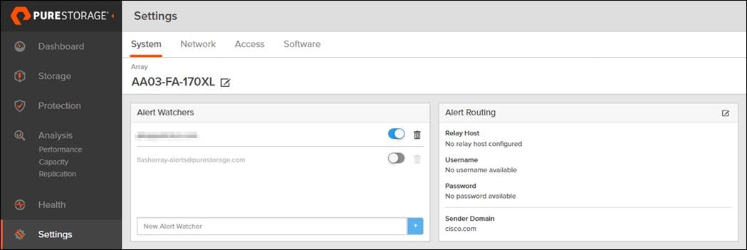
The Relay Host section displays the hostname or IP address of an SMTP relay host if one is configured for the array. If you specify a relay host, Purity routes the email messages via the relay (mail forwarding) address rather than sending them directly to the alert recipient addresses.
In the Sender Domain section, the sender domain determines how Purity logs are parsed and treated by Pure Storage Support and Escalations. By default, the sender domain is set to the domain name please-configure.me.
It is crucial that you set the sender domain to the correct domain name. If the array is not a Pure Storage test array, set the sender domain to the actual customer domain name. For example, mycompany.com.
The Pure1 Support section manages settings for Phone Home, Remote Assist, and Support Logs.
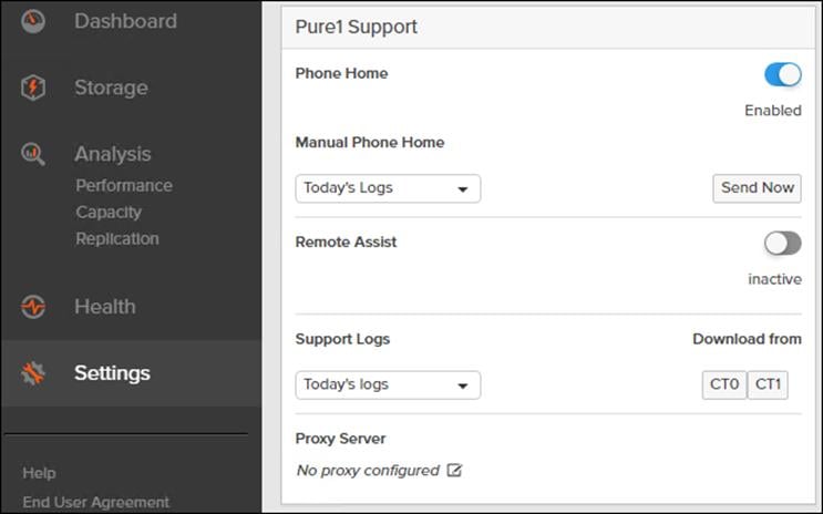
● The phone home facility provides a secure direct link between the array and the Pure Storage Technical Support web site. The link is used to transmit log contents and alert messages to the Pure Storage Support team so that when diagnosis or remedial action is required, complete recent history about array performance and significant events is available. By default, the phone home facility is enabled. If the phone home facility is enabled to send information automatically, Purity transmits log and alert information directly to Pure Storage Support via a secure network connection. Log contents are transmitted hourly and stored at the support web site, enabling detection of array performance and error rate trends. Alerts are reported immediately when they occur so that timely action can be taken.
● Phone home logs can also be sent to Pure Storage Technical support on demand, with options including Today's Logs, Yesterday's Logs, or All Log History.
The Remote Assist section displays the remote assist status as "Connected" or "Disconnected". By default, remote assist is disconnected. A connected remote assist status means that a remote assist session has been opened, allowing Pure Storage Support to connect to the array. Disconnect the remote assist session to close the session.
● The Support Logs section allows you to download the Purity log contents of the specified controller to the current administrative workstation. Purity continuously logs a variety of array activities, including performance summaries, hardware and operating status reports, and administrative actions.
Configure DNS Server IP Addresses
Procedure 1. Configure the DNS Server IP Addresses
Step 1. Click Settings > Network.
Step 2. In the DNS section, hover over the domain name and click the pencil icon. The Edit DNS dialog box appears.
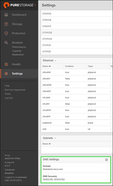
Step 3. Complete the following fields:
a. Domain: Specify the domain suffix to be appended by the array when doing DNS lookups.
b. NS#: Specify up to three DNS server IP addresses for Purity to use to resolve hostnames to IP addresses. Enter one IP address in each DNS# field. Purity queries the DNS servers in the order that the IP addresses are listed.
Step 4. Click Save.
The Directory Service manages the integration of FlashArray with an existing directory service. When the Directory Service sub-view is configured and enabled, the FlashArray leverages a directory service to perform user account and permission level searches. Configuring directory services is OPTIONAL.
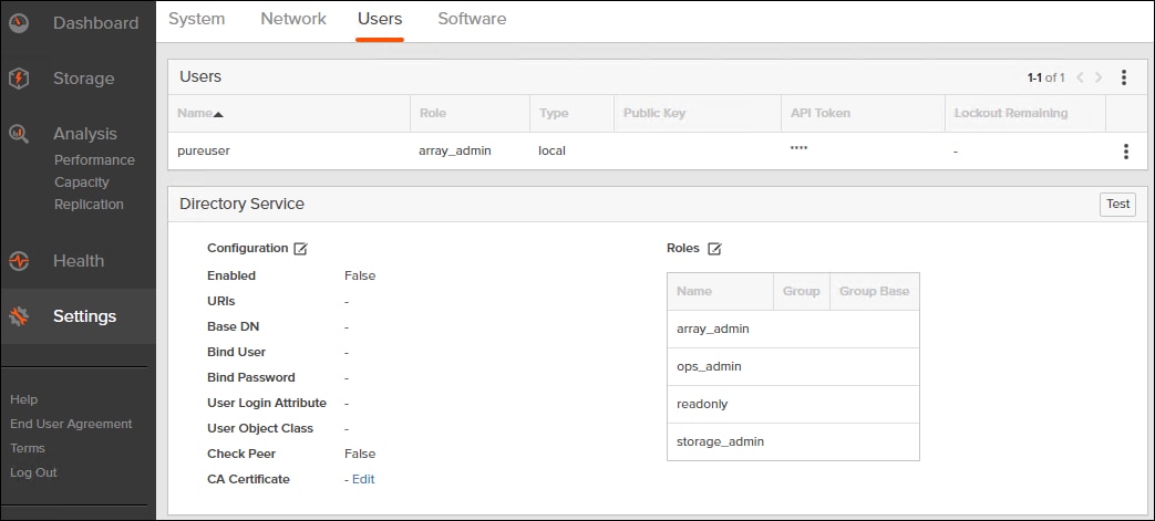
The FlashArray is delivered with a single local user, named pureuser, with array-wide (Array Admin) permissions.
To support multiple FlashArray users, integrate the array with a directory service, such as Microsoft Active Directory or OpenLDAP.
Role-based access control is achieved by configuring groups in the directory that correspond to the following permission groups (roles) on the array:
● Read Only Group. Read Only users have read-only privilege to run commands that convey the state of the array. Read Only uses cannot alter the state of the array.
● Storage Admin Group. Storage Admin users have all the privileges of Read Only users, plus the ability to run commands related to storage operations, such as administering volumes, hosts, and host groups. Storage Admin users cannot perform operations that deal with global and system configurations.
● Array Admin Group. Array Admin users have all the privileges of Storage Admin users, plus the ability to perform array-wide changes. In other words, Array Admin users can perform all FlashArray operations.
Procedure 1. Configure the Directory Service
Step 1. Click Settings > Access > Users.
Step 2. Select the![]() icon in the Directory Services panel:
icon in the Directory Services panel:
● Enabled: Select the check box to leverage the directory service to perform user account and permission level searches.
● URI: Enter the comma-separated list of up to 30 URIs of the directory servers. The URI must include a URL scheme (ldap, or ldaps for LDAP over SSL), the hostname, and the domain. You can optionally specify a port. For example, ldap://ad.company.com configures the directory service with the hostname "ad" in the domain "company.com" while specifying the unencrypted LDAP protocol.
● Base DN: Enter the base distinguished name (DN) of the directory service. The Base DN is built from the domain and should consist only of domain components (DCs). For example, for ldap://ad.storage.company.com, the Base DN would be: “DC=storage,DC=company,DC=com”
● Bind User: Username used to bind to and query the directory. For Active Directory, enter the username - often referred to as sAMAccountName or User Logon Name - of the account that is used to perform directory lookups. The username cannot contain the characters " [ ] : ; | = + * ? < > / \ and cannot exceed 20 characters in length. For OpenLDAP, enter the full DN of the user. For example, "CN=John,OU=Users,DC=example,DC=com".
● Bind Password: Enter the password for the bind user account.
● Group Base: Enter the organizational unit (OU) to the configured groups in the directory tree. The Group Base consists of OUs that, when combined with the base DN attribute and the configured group CNs, complete the full Distinguished Name of each groups. The group base should specify "OU=" for each OU and multiple OUs should be separated by commas. The order of OUs should get larger in scope from left to right. In the following example, SANManagers contains the sub-organizational unit PureGroups: "OU=PureGroups,OU=SANManagers".
● Array Admin Group: Common Name (CN) of the directory service group containing administrators with full privileges to manage the FlashArray. Array Admin Group administrators have the same privileges as pureuser. The name should be the Common Name of the group without the "CN=" specifier. If the configured groups are not in the same OU, also specify the OU. For example, "pureadmins,OU=PureStorage", where pureadmins is the common name of the directory service group.
● Storage Admin Group: Common Name (CN) of the configured directory service group containing administrators with storage related privileges on the FlashArray. The name should be the Common Name of the group without the "CN=" specifier. If the configured groups are not in the same OU, also specify the OU. For example, "pureusers,OU=PureStorage", where pureusers is the common name of the directory service group.
● Read Only Group: Common Name (CN) of the configured directory service group containing users with read-only privileges on the FlashArray. The name should be the Common Name of the group without the "CN=" specifier. If the configured groups are not in the same OU, also specify the OU. For example, "purereadonly,OU=PureStorage", where purereadonly is the common name of the directory service group.
● Check Peer: Select the check box to validate the authenticity of the directory servers using the CA Certificate. If you enable Check Peer, you must provide a CA Certificate.
● CA Certificate: Enter the certificate of the issuing certificate authority. Only one certificate can be configured at a time, so the same certificate authority should be the issuer of all directory server certificates. The certificate must be PEM formatted (Base64 encoded) and include the "-----BEGIN CERTIFICATE-----" and "-----END CERTIFICATE-----" lines. The certificate cannot exceed 3000 characters in total length.
Step 3. Click Save.
Step 4. Click Test to test the configuration settings. The LDAP Test Results pop-up window appears. Green squares represent successful checks. Red squares represent failed checks.
Self-Signed Certificate
Purity creates a self-signed certificate and private key when you start the system for the first time. The SSL Certificate sub-view allows you to view and change certificate attributes, create a new self-signed certificate, construct certificate signing requests, import certificates and private keys, and export certificates.
Creating a self-signed certificate replaces the current certificate. When you create a self-signed certificate, include any attribute changes, specify the validity period of the new certificate, and optionally generate a new private key.
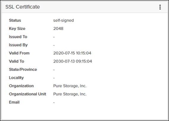
When you create the self-signed certificate, you can generate a private key and specify a different key size. If you do not generate a private key, the new certificate uses the existing key.
You can change the validity period of the new self-signed certificate. By default, self-signed certificates are valid for 3650 days
CA-Signed Certificate
Certificate authorities (CA) are third party entities outside the organization that issue certificates. To obtain a CA certificate, you must first construct a certificate signing request (CSR) on the array.
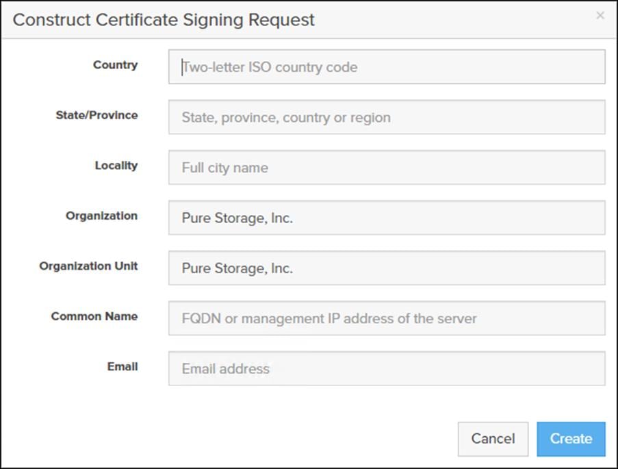
The CSR represents a block of encrypted data specific to your organization. You can change the certificate attributes when you construct the CSR; otherwise, Purity will reuse the attributes of the current certificate (self-signed or imported) to construct the new one. Note that the certificate attribute changes will only be visible after you import the signed certificate from the CA.
Send the CSR to a certificate authority for signing. The certificate authority returns the SSL certificate for you to import. Verify that the signed certificate is PEM formatted (Base64 encoded), includes the "-----BEGIN CERTIFICATE-----" and "-----END CERTIFICATE-----" lines, and does not exceed 3000 characters in total length. When you import the certificate, also import the intermediate certificate if it is not bundled with the CA certificate.
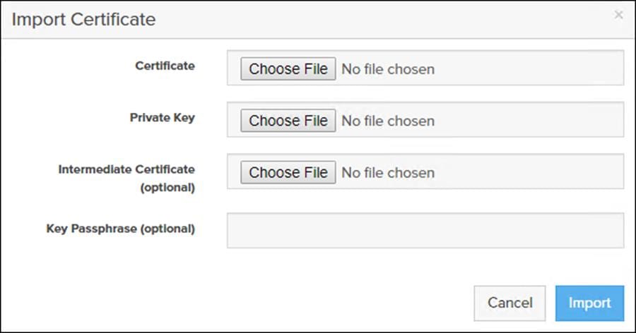
If the certificate is signed with the CSR that was constructed on the current array and you did not change the private key, you do not need to import the key. However, if the CSR was not constructed on the current array or if the private key has changed since you constructed the CSR, you must import the private key. If the private key is encrypted, also specify the passphrase.
If FC-NVMe is being implemented, the FC ports personality on the FlashArray need to be converted to nvme-fc from the default scsi-fc. In this design we have used two scsi-fc and two nvme-fc ports to support both SCSI and NVMe over Fibre Channel. The ports can be converted to nvme-fc with the help of Pure support.
FlashArray Storage Deployment for SCSI-FC and NVMe-FC
The Pure Storage FlashArray//XL is accessible to the FlashStack, but no storage has been deployed at this point. The storage to be deployed will include:
● ESXi FC Boot LUNs
● VMFS Datastores
● FC-NVMe Data stores
The FC Boot LUNs will need to be setup from the Pure Storage Web Portal, and the VMFS datastores can be provisioned from the Pure Storage Web Portal or can be directly provisioned from the vSphere Web Client after the Pure Storage vSphere Web Client Plugin has later been registered with the vCenter.
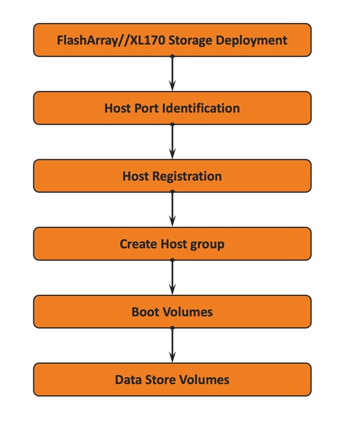
FC Boot LUNs will be mapped by the FlashArray//XL using the assigned Initiator PWWN to the provisioned server profiles. This information can be found within the server profile located within the Cisco Intersight > Configure > UCS Server Profiles:
Procedure 1. Register the Host from the Pure Storage Web Portal
Step 1. Click Storage > Hosts.
Step 2. Select the + icon in the Hosts Panel.
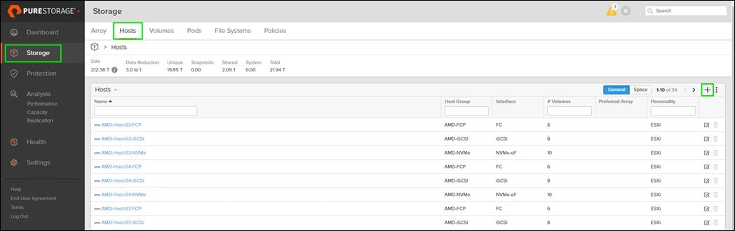
Step 3. After clicking the Create Host (+) option, a pop-up will appear to create an individual host entry on the FlashArray.
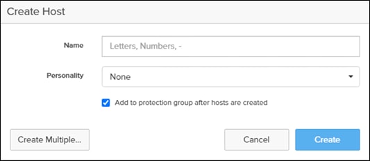
Step 4. To create more than one host entry, click the Create Multiple… option, filling in the Name, Start Number, Count, Personality as ESXi and Number of Digits, with a “#” appearing in the name where an iterating number will appear:
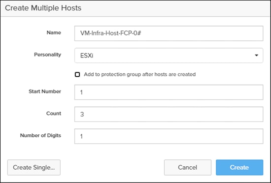
Step 5. Click Create to add the hosts.
Step 6. For each host created, select the host.
Step 7. In the Host view, select Configure WWNs… from the Host Ports menu.
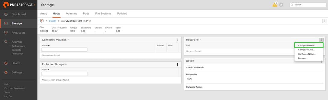
Step 8. A pop-up will appear for Configure Fibre Channel WWNs for <host being configured>. Within this pop-up, select the appropriate Existing WWNs from the discovered list.
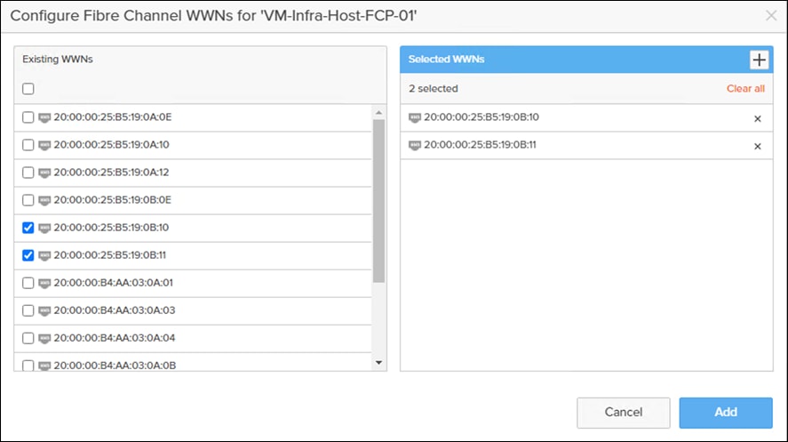
Step 9. Or you may enter the WWN manually by selecting the +.
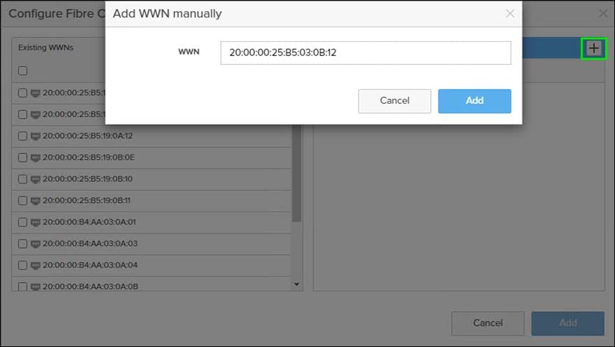
Step 10. After entering the PWWN/WWPN, click Add to add the Host Ports.
Step 11. Repeat steps 1-10 for each host created.
Procedure 2. Create Host Group from the Pure Storage Web Portal
Step 1. Click Storage > Hosts.
Step 2. Select the + icon in the Host Groups Panel.
A pop-up will appear to create a host group on the FlashArray.
Step 3. Provide a name for the group and click Create.
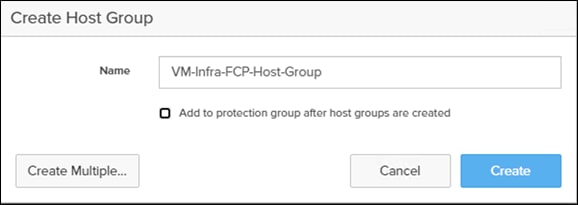
Step 4. Select the group in the Host Groups Panel.
Step 5. In the Host Group view, select Add… from the Member Hosts menu.
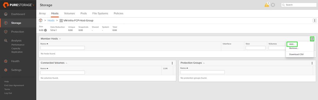
Step 6. Select the host to be part of the host group.
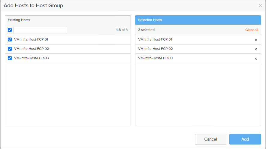
Step 7. Click Add.
Private Boot Volumes for each ESXi Host
Procedure 1. Create Private Boot Volumes for each ESXi Host from the Pure Storage Web Portal
Step 1. Click Storage > Volumes.
Step 2. Select the + icon in the Volumes Panel.
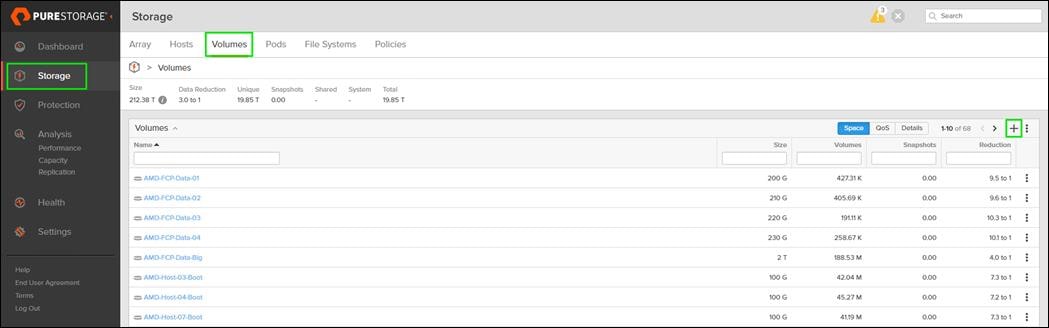
A pop-up will appear to create a volume on the FlashArray.
Step 3. To create more than one volume, click the Create Multiple… option, filling in the Name, Provisioned Size, Staring Number, Count, and Number of Digits, with a “#” appearing in the name where an iterating number will appear.
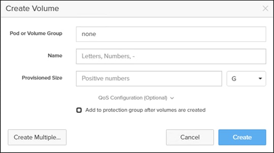
Step 4. Click Create to provision the volumes to be used as FC boot LUNs.
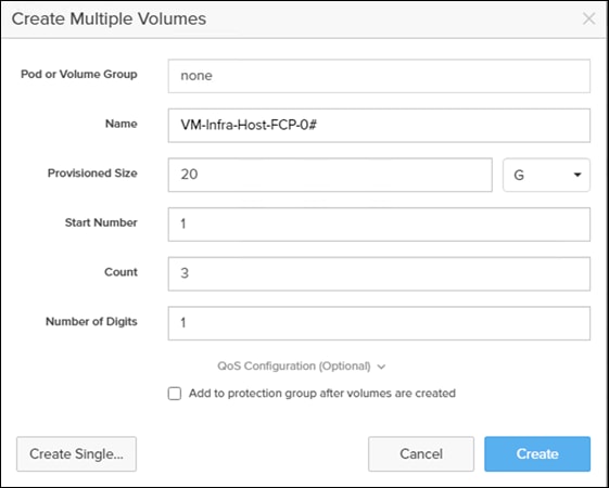
Step 5. Return to the Hosts section under the Storage tab. Click one of the hosts and select the gear icon drop-down within the Connected Volumes tab within that host.
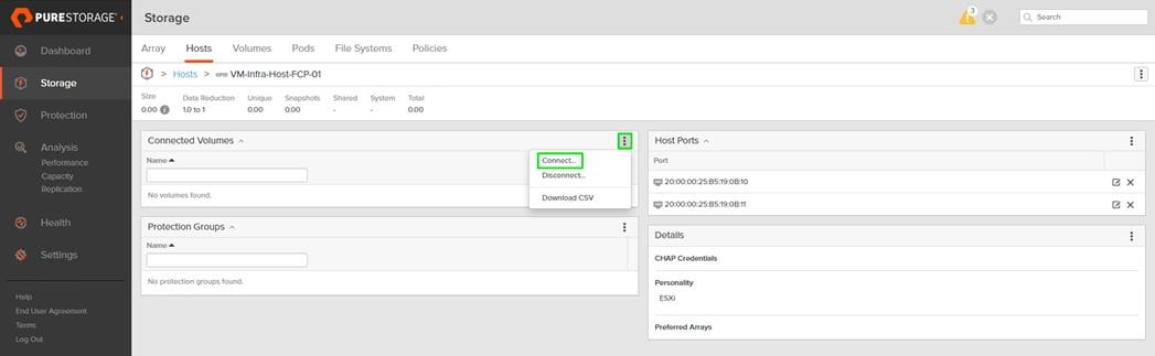
Step 6. From the drop-down list of the gear icon, select Connect Volumes, and a pop-up will appear.
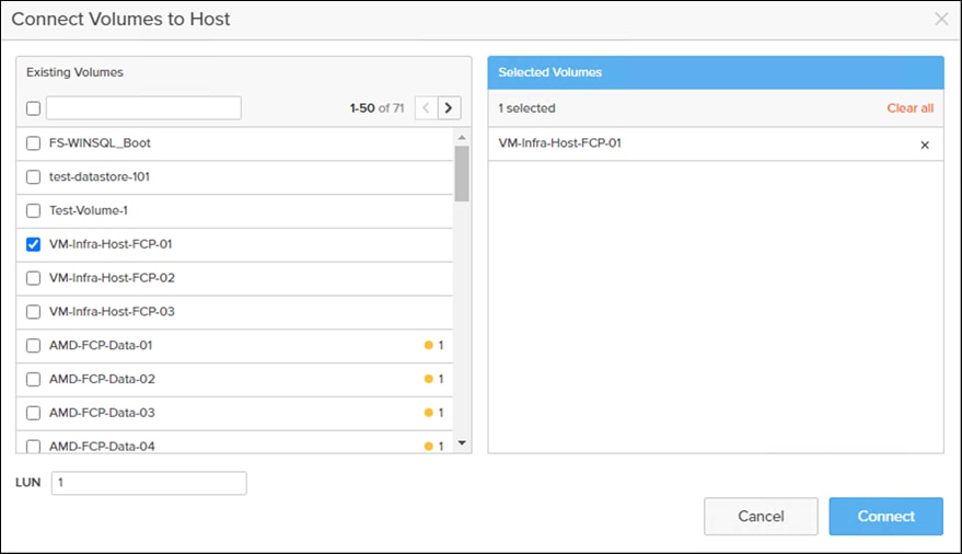
Note: LUN ID 1 should be used for the boot.
Step 7. Select the volume that has been provisioned for the host, set the LUN ID for the volume, click the + next to the volume, and select Confirm to proceed. Repeat the steps for connecting volumes for each of the host/volume pairs configured.
Create Infra Datastores
Procedure 1. Create Datastore Volumes for the ESXi Cluster from the Pure Storage Web Portal
Step 1. Click Storage > Volumes.
Step 2. Select the + icon in the Volumes Panel.
A pop-up will appear to create a volume on the FlashArray.
Step 3. Fill in the Name and Provisioned Size.
Step 4. Click Create to provision the volumes to be used as Infra datastore LUN.
Step 5. Return to the Hosts section under the Storage tab. Click ESXi cluster host group created earlier and select the gear icon drop-down within the Connected Volumes tab within that host group.
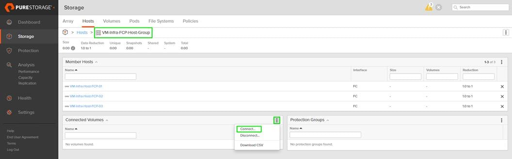
Step 6. Within the drop-down list of the gear icon, select Connect Volumes, and a pop-up will appear.
Step 7. Select the Infra datastore volume that has been provisioned for the host group, leave the LUN ID for the volume to Automatic, click Connect.
Configure Storage Policy Based Management
vSphere can communicate to the array via VASA provider to find out what features it supports and allow the vSphere administrator to assign, change, or remove functionality on a VVol on demand and via policies. Below is an example of how to configure a Protection group that will provide hourly snapshots that will be retained for 1 day, with 4 snapshots per day retained for 7 days. These policies should be configured based on application snapshot need.
Procedure 1. Configure Storage Policy Based Management
Step 1. From the Pure Storage Web Portal, click Protection > Protection Groups > select the + icon in the Source Protection Groups.
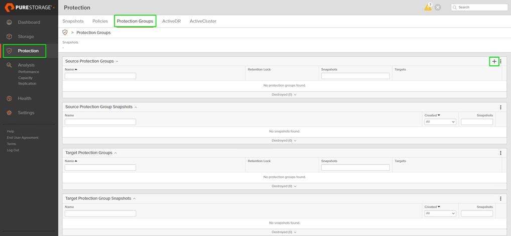
Step 2. Enter a name.
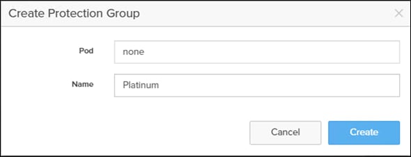
Step 3. Select the protection group.
Step 4. Click the edit icon.
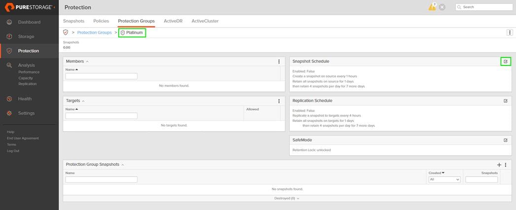
Step 5. Edit the Snapshot Schedule based on your operational requirements.
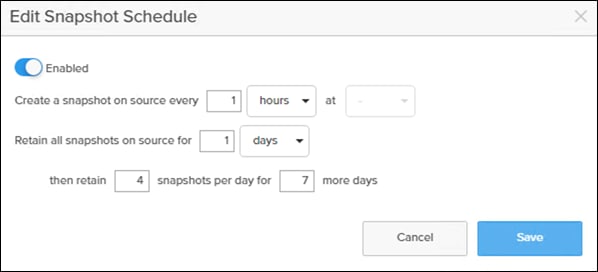
Step 6. Click Save.
FlashArray //XL170 iSCSI Interface Configuration
The iSCSI traffic will be carried on two VLANs, A (3119) and B (3219) that are configured in our example with the following values listed in Table 25.
Table 25.iSCSI A FlashArray//XL170 Interface Configuration Settings
| FlashArray Controller |
iSCSI Port |
IP Address |
Subnet Mask |
| FlashArray//XL170 Controller 0 |
CT0.ETH10 |
192.168.31.4 |
255.255.255.0 |
| FlashArray//XL170 Controller 1 |
CT1.ETH10 |
192.168.31.5 |
255.255.255.0 |
Table 26.iSCSI B FlashArray//XL170 Interface Configuration Settings
| FlashArray Controller |
iSCSI Port |
IP Address |
Subnet Mask |
| FlashArray//XL170 Controller 0 |
CT0.ETH11 |
192.168.32.4 |
255.255.255.0 |
| FlashArray//XL170 Controller 1 |
CT1.ETH11 |
192.168.32.5 |
255.255.255.0 |
Procedure 1. Configure iSCSI Interfaces for Environments Deploying iSCSI Boot LUNs and/or datastores from the Pure FlashArray Web Portal
Step 1. Click Settings > Network.
Step 2. Click Edit for interface CT0.eth10
Step 3. Click Enable and add the IP information from the above tables and set the MTU to 9000.
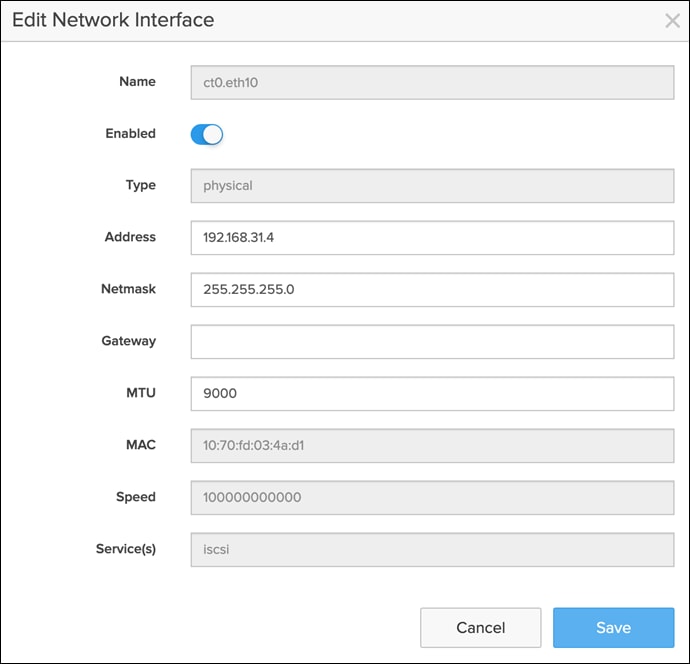
Step 4. Click Save.
Step 5. Repeat steps 1-4 for CT0.eth5, CT1.eth4, and CT1.eth5.
FlashArray Storage Deployment for iSCSI
The Pure Storage FlashArray//XL170 and FlashArray//X50 R3 are accessible to the FlashStack, but no storage has been deployed at this point. The storage to be deployed will include:
● ESXi iSCSI Boot LUNs
● VMFS Datastores
● vVOL Data Stores
The iSCSI Boot LUNs will need to be setup from the Pure Storage Web Portal, and the VMFS datastores can be directly provisioned from the vSphere Web Client after the Pure Storage vSphere Web Client Plugin has later been registered with the vCenter.
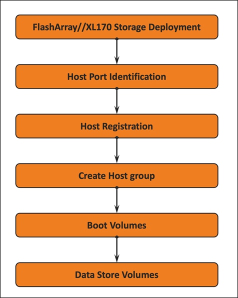
iSCSI Boot LUNs will be mapped by the FlashArray//XL170 and FlashArray//X50 R3 using the assigned Initiator IQN to the provisioned server profiles.
Procedure 1. Retrieve Information within the Service Profile from the iSCSI vNIC tab
Step 1. From Service Selector, select Infrastructure Service.
Step 2. From the left navigation pane, select Configure and click on Pools.
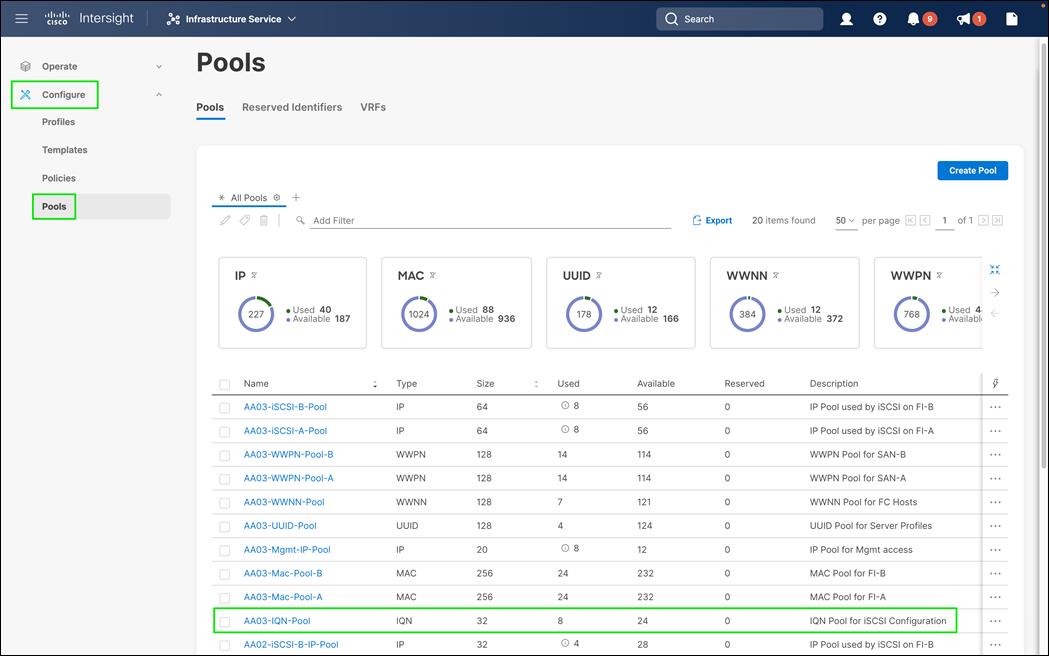
Step 3. Click on the IQN Pool created, (for example, AA03-IQN-Pool).
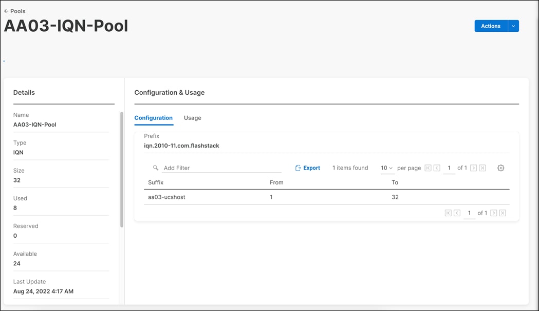
Step 4. Click the Usage tab.
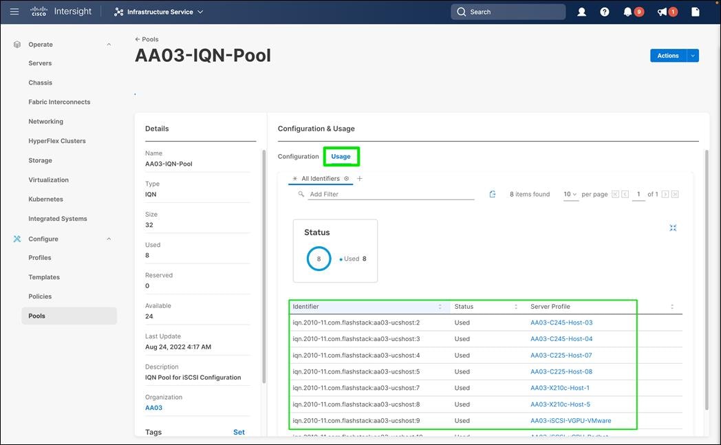
Step 5. Copy the IQN for the server profile.
Procedure 1. Register the Host from the Pure Storage Web Portal
Step 1. Click Storage > Hosts.
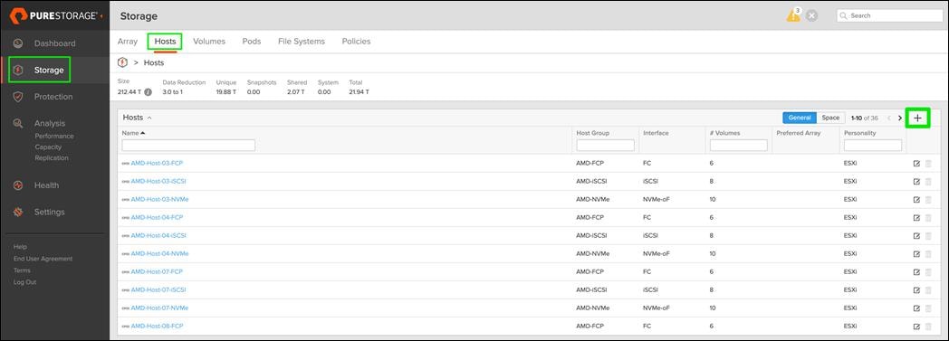
Step 2. Select the + icon in the Hosts Panel.
Step 3. After clicking the Create Host (+) option, a pop-up will appear to create an individual host entry on the FlashArray.
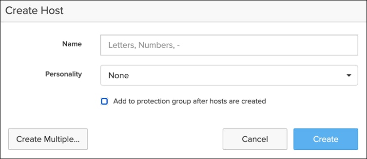
Step 4. To create more than one host entry, click the Create Multiple… option, filling in the Name, Start Number, Count, Personality as ESXi and Number of Digits, with a “#” appearing in the name where an iterating number will appear:

Step 5. Click Create to add the hosts.
Step 6. For each host created, select the host.
Step 7. In the Host view, select Configure IQNs… from the Host Ports menu.
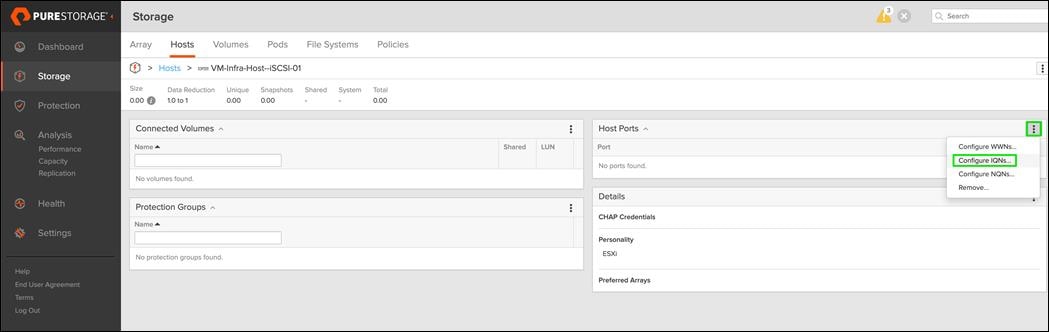
Step 8. A pop-up will appear for Configure iSCSI IQNs for Host <host being configured>. Within this pop-up, enter the IQN Initiator Name found within the service profile for the host being configured:
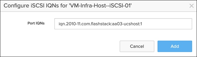
Step 9. After entering the IQN, click Add to add the Host Ports.
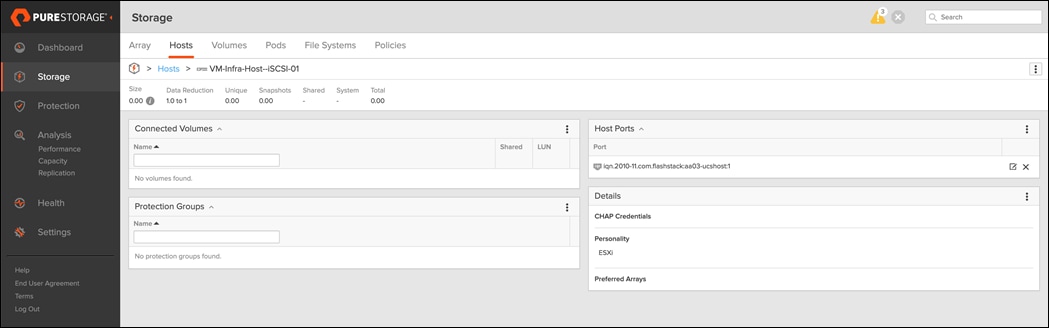
Step 10. Repeat steps 1-9 for each host created.
Create Host Group
Host Groups allow the Administrator to map Volumes to a group of hosts at once with the same LUN ID.
Procedure 1. Create a Host Group, from the Pure Storage Web Portal
Step 1. Click Storage > Hosts.
Step 2. Select the + icon in the Host Groups Panel.
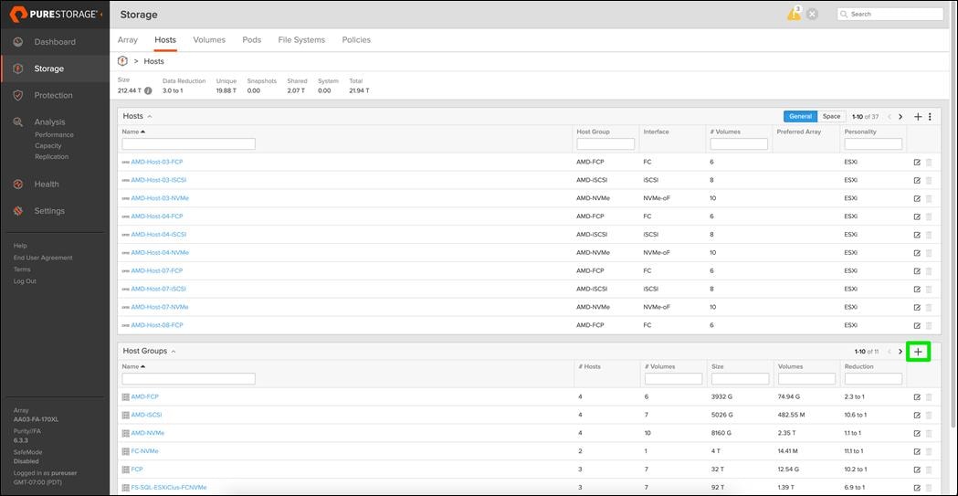
A pop-up will appear to create a host group on the FlashArray.
Step 3. Provide a name for the group and click Create.
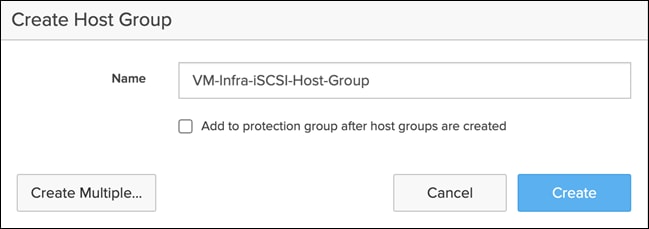
Step 4. Select the group in the Host Groups Panel.
Step 5. In the Host Group view, select Add… from the Member Hosts menu.

Step 6. Select the host to be part of the host group.
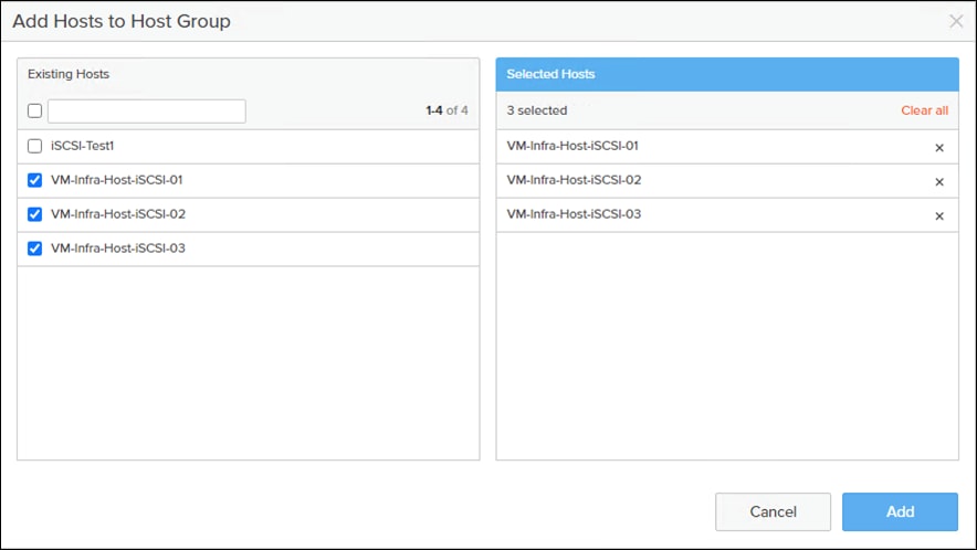
Step 7. Click Add.
Private Boot Volumes for each ESXi Host
Procedure 1. Create Private Boot Volumes for each ESXi Host from the Pure Storage Web Portal
Step 1. Click Storage > Volumes.
Step 2. Select the + icon in the Volumes Panel.
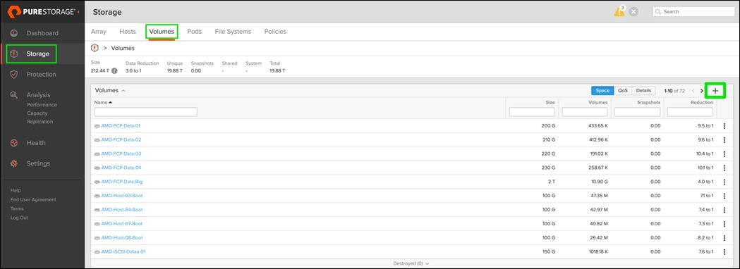
A pop-up will appear to create a volume on the FlashArray.
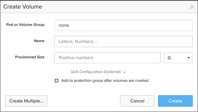
Step 3. To create more than one volume, click the Create Multiple… option, filling in the Name, Provisioned Size, Staring Number, Count, and Number of Digits, with a “#” appearing in the name where an iterating number will appear.
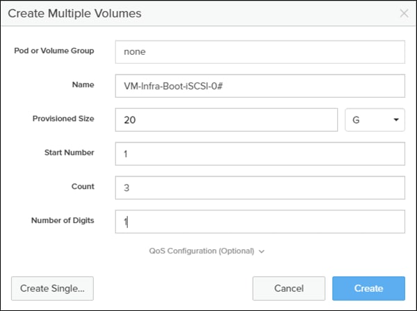
Step 4. Click Create to provision the volumes to be used as iSCSI boot LUNs.
Step 5. Go back to the Hosts section under the Storage tab. Click one of the hosts and select the gear icon drop-down within the Connected Volumes tab within that host.
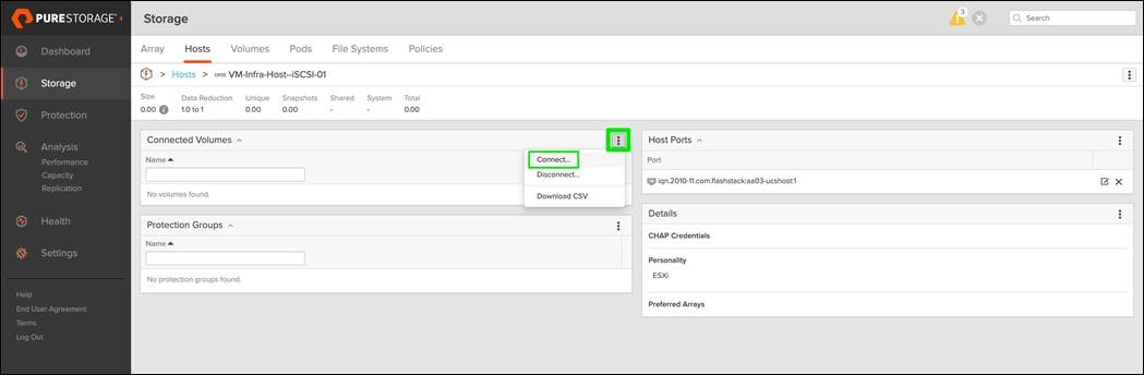
Step 6. From the drop-down list of the gear icon, select Connect Volumes, and a pop-up will appear.
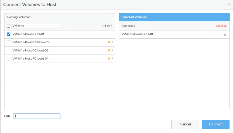
Note: LUN ID 1 should be used for the boot .
Step 7. Select the volume that has been provisioned for the host, set the LUN ID for the volume, click the + next to the volume, and select Confirm to proceed. Repeat the steps for connecting volumes for each of the host/volume pairs configured.
Create Infra Datastores
Procedure 1. Create Datastore Volumes for the ESXi Cluster from the Pure Storage Web Portal
Step 1. Click Storage > Volumes.
Step 2. Select the + icon in the Volumes Panel.
A pop-up will appear to create a volume on the FlashArray.
Step 3. Fill in the Name and Provisioned Size.
Step 4. Click Create to provision the volumes to be used as Infra datastore LUN.
Step 5. Go back to the Hosts section under the Storage tab. Click the ESXi cluster host group created earlier and select the gear icon pull-down within the Connected Volumes tab within that host group.
Step 6. From the drop-down list of the gear icon, select Connect Volumes, and a pop-up will appear.
Step 7. Select the Infra datastore volume that has been provisioned for the host group, leave the LUN ID for the volume to Automatic, click Connect.
Set Up VMware ESXi Installation
This section provides detailed instructions for installing VMware ESXi 7.0 U3 in a FlashStack environment. After the procedures are completed, three booted ESXi hosts will be provisioned.
Several methods exist for installing ESXi in a VMware environment. These procedures focus on how to use the built-in keyboard, video, mouse (KVM) console and virtual media features in Cisco Intersight to map remote installation media to individual servers and connect to their boot logical unit numbers (LUNs).
Procedure 1. Download ESXi 7.0 U3 from VMware
If the VMware ESXi ISO has not already been downloaded, follow these steps:
Step 1. Click this link: https://customerconnect.vmware.com/downloads/details?downloadGroup=OEM-ESXI70U3-CISCO&productId=974
Note: You will need a user id and password on vmware.com to download this software.
Step 2. Download the .iso file.
Procedure 2. Log into Cisco Intersight and Access KVM
Step 1. Open a browser to Cisco Intersight, https://intersight.com
Step 2. Login to Cisco Intersight.
Step 3. From Service Selector, select Infrastructure Service.
Step 4. From the left navigation pane, select Operate > Servers.

Step 5. Select the server. From row actions, select Launch the vKVM.
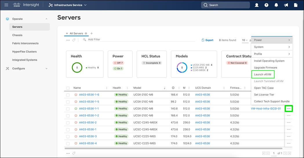
Note: Make sure the host trying to access the KVM can route to the management IP address pool.
Note: Since the Cisco Custom ISO image will be mapped to the vKVM, it is important to use the standard vKVM and not the Tunneled vKVM and that the Cisco Intersight interface is being run from a subnet that has direct access to the subnet that the CIMC IPs (10.102.0.213 in this example) are provisioned on.
Step 6. Follow the prompts to ignore certificate workings (if any) and launch the HTML5 KVM console.
Step 7. Repeat steps 1 – 6 to launch the HTML5 KVM console for all the ESXi servers.
Procedure 3. Prepare the Server for the OS Installation on each ESXi Host
Step 1. In the KVM window, click Virtual Media > vKVM-Mapped vDVD
Step 2. Browse and select the ESXi installer ISO image file downloaded in the last in Procedure 1 above (VMware-ESXi-7.0.3d-19482537-Custom-Cisco-4.2.2-a).
Step 3. Click Map Drive.
Step 4. Select Power > Reset System and Confirm to reboot the Server if the server is showing shell prompt. If the server is shutdown, select Power > Power On System.
Step 5. Monitor the server boot process in the KVM. The server should find the boot LUNs and begin to load the ESXi installer.
Note: If the ESXi installer fails to load because the software certificates cannot be validated, reset the server, and when prompted, press F2 to go into BIOS and set the system time and date to current. The ESXi installer should load properly.
Step 6.
Procedure 1. Install VMware ESXi to the Bootable LUN of the Hosts
Step 1. After the ESXi installer is finished loading (from the last step), press Enter to continue with the installation.
Step 2. Read and accept the end-user license agreement (EULA). Press F11 to accept and continue.
Note: It may be necessary to map function keys as User Defined Macros under the Macros menu in the KVM console.
Step 3. Select the LUN that was previously set up as the installation disk for ESXi and press Enter to continue with the installation
Step 4. Select the appropriate keyboard layout and press Enter.
Step 5. Enter and confirm the root password and press Enter.
Step 6. The installer issues a warning that the selected disk will be repartitioned. Press F11 to continue with the installation.
Step 7. After the installation is complete, press Enter to reboot the server. The ISO will be unmapped automatically.
Set Up Management Networking for ESXi Hosts
Add the Management Network for each VMware Host
Adding a management network for each VMware host is necessary for managing the host. The following section details how to add a management network for the VMware hosts.
Procedure 1. Configure each ESXi Host with Access to the Management Network
Step 1. After the server has finished rebooting, in the UCS KVM console, press F2 to customize VMware ESXi.
Step 2. Log in as root, enter the corresponding password, and press Enter to log in.
Step 3. Use the down arrow key to select Troubleshooting Options and press Enter.
Step 4. Select Enable ESXi Shell and press Enter.
Step 5. Select Enable SSH and press Enter.
Step 6. Press Esc to exit the Troubleshooting Options menu.
Step 7. Select the Configure Management Network option and press Enter.
Step 8. Select Network Adapters and press Enter.
Step 9. Verify that the numbers in the Hardware Label field match the numbers in the Device Name field. If the numbers do not match, note the mapping of vmnic ports to vNIC ports for later use.
Step 10. Using the spacebar, select vmnic1.
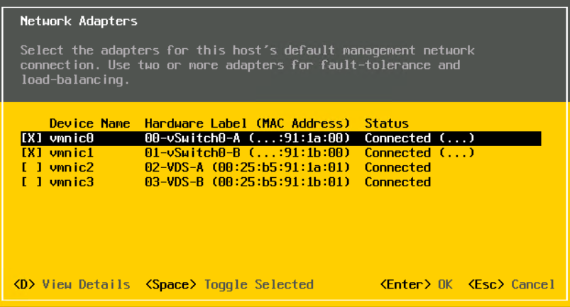
Note: In lab testing, examples have been seen where the vmnic and device ordering do not match. If this is the case, use the Consistent Device Naming (CDN) to note which vmnics are mapped to which vNICs and adjust the upcoming procedure accordingly.
Step 11. Press Select .
Step 12. Enter the <ib-mgmt-vlan-id> and press Select .
Step 13. Choose Select and press Select .
Step 14. Choose the “Select ” option by using the arrow keys and space bar.
Step 15. Move to the IPv4 Address field and enter the IP address for managing the ESXi host.
Step 16. Move to the Subnet Mask field and enter the subnet mask for the ESXi host.
Step 17. Move to the Default Gateway field and enter the default gateway for the ESXi host.
Step 18. Press Select to accept the changes to the IP configuration.
Step 19. Select the Select option and press Enter.
Step 20. Using the spacebar, choose Select and press Select .
Step 21. Choose the Select option and press Select .
Note: Since the IP address is assigned manually, the DNS information must also be entered manually.
Step 22. Using the spacebar, select “Select :”
Step 23. Move to the Primary DNS Server field and enter the IP address of the primary DNS server.
Step 24. Optional: Move to the Alternate DNS Server field and enter the IP address of the secondary DNS server.
Step 25. Move to the Hostname field and enter the fully qualified domain name (FQDN) for the ESXi host.
Step 26. Press Select to accept the changes to the DNS configuration.
Step 27. Press Select to exit the Configure Management Network submenu.
Step 28. Press Select to confirm the changes and reboot the ESXi host.
Reset VMware ESXi Host VMkernel Port vmk0 MAC Address (Optional)
By default, the MAC address of the management VMkernel port vmk0 is the same as the MAC address of the Ethernet port it is placed on. If the ESXi host’s boot LUN is remapped to a different server with different MAC addresses, a MAC address conflict will exist because vmk0 will retain the assigned MAC address unless the ESXi System Configuration is reset.
Procedure 1. Reset The MAC Address Of Vmk0 To A Random Vmware-Assigned MAC Address
Step 1. From the ESXi console menu main screen, type Ctrl-Alt-F1 to access the VMware console command line interface. In the UCSM KVM, Ctrl-Alt-F1 appears in the list of Static Macros.
Step 2. Log in as root.
Step 3. Type esxcfg-vmknic –l to get a detailed listing of interface vmk0. vmk0 should be a part of the “Management Network” port group. Note the IP address and netmask of vmk0.
Step 4. To remove vmk0, type esxcfg-vmknic –d “Management Network”.
Step 5. To add vmk0 with a random MAC address, type esxcfg-vmknic –a –i <vmk0-ip> -n <vmk0-netmask> “Management Network”.
Step 6. Verify vmk0 has been re-added with a random MAC address by typing esxcfg-vmknic –l.
Step 7. Tag vmk0 as the management interface by typing esxcli network ip interface tag add -i vmk0 -t Management.
Step 8. When vmk0 was re-added, if a message displays stating vmk1 was marked as the management interface, type esxcli network ip interface tag remove -i vmk1 -t Management.
Step 9. If this VMware ESXi host is iSCSI booted, the vmk1, iScsiBootPG-A interface’s MAC address can also be reset to a random, VMware-assigned MAC address.
a. Type esxcfg-vmknic –l to get a detailed listing of interface vmk1. vmk1 should be a part of the “iScsiBootPG-A” port group and should have a MAC address from the UCS MAC Pool. Note the IP address and netmask of vmk1.
b. To remove vmk1, type esxcfg-vmknic –d “iScsiBootPG-A”.
c. To add vmk1 with a random MAC address, type esxcfg-vmknic –a –i <vmk1-ip> -n <vmk1-netmask> -m 9000 “iScsiBootPG-A”.
d. Verify vmk1 has been re-added with a random MAC address by typing esxcfg-vmknic –l.
e. Type exit to log out of the command line interface.
Step 10. Type Ctrl-Alt-F2 to return to the ESXi console menu interface.
Install VMware and Cisco VIC Drivers for the ESXi Host
Download Drivers to the Management Workstation
Download the offline bundle for the UCS Tools Component and VMware VIC Driver to the Management workstation:
● nfnic driver 5.0.0.34: https://customerconnect.vmware.com/downloads/details?downloadGroup=DT-ESXI70-CISCO-NFNIC-50034&productId=974
● Cisco UCS Tools Component for ESXi 7.0 1.2.1 (ucs-tool-esxi_1.2.1-1OEM.zip)
Note: The Cisco VIC nenic version 1.0.42.0 is already included in the Cisco Custom ISO for VMware vSphere version 7.0.3.
Note: This document uses the driver versions shown above. These were the versions validated and supported at the time this document was published. This document can be used as a guide for configuring future versions of software. Consult the Cisco UCS Hardware Compatibility List and the Pure Interoperability Matrix Tool to determine supported combinations
Install VMware Drivers
Procedure 1. Install Cisco UCS Tools on the ESXi host ESXi VM-Host-Infra-FCP-01, VM-Host-Infra-FCP-02, and VM-Host-Infra-FCP-03
Note: The latest nenic driver is already included with the ESXi install ISO and is not required to be updated if the Cisco Custom ISO for ESXi 7.0 U2 is used.
Step 1. Using an SCP program such as WinSCP, copy the two offline bundles referenced above to the /tmp directory on each ESXi host.
Step 2. Using a ssh tool such as PuTTY, ssh to each VMware ESXi host. Log in as root with the root password.
Step 3. Type cd /tmp.
Step 4. Run the following commands on each host:
esxcli software component apply -d /tmp/Cisco-nfnic_5.0.0.34-1OEM.700.1.0.15843807_19966277.zip
esxcli software component apply -d /tmp/ucs-tool-esxi_1.2.1-1OEM.zip
reboot
Step 5. After reboot, log back into each host and run the following commands and ensure the correct version is installed:
esxcli software vib list | grep nenic
esxcli software component list | grep nfnic
esxcli software component list | grep ucs
VMware ESXi Configuration
Procedure 1. VMware ESXi Configuration for the first ESXi Host (VM-Host-Infra-FCP-01)
Step 1. Open a web browser on the management workstation and navigate to the VM-Host-Infra-FCP-01 management IP address.
Step 2. Enter root for the User name.
Step 3. Enter the root password.
Step 4. Click Login to connect.
Step 5. Decide whether to join the VMware Customer Experience Improvement Program and click OK.
Procedure 2. Set Up VMkernel Ports and Virtual Switch on the first ESXi Host
Note: In this procedure, you’re only setting up the first ESXi host. The second and third hosts will be added to vCenter and setup from the vCenter HTML5 Interface.
Step 1. From the Host Client Navigator, select Networking.
Step 2. In the center pane, select the Virtual switches tab.
Step 3. Highlight the vSwitch0 line.
Step 4. Click Edit settings.
Step 5. Change the MTU to 9000.
Step 6. Expand NIC teaming.
Step 7. In the Failover order section, select vmnic1 and click Mark active.
Step 8. Verify that vmnic1 now has a status of Active.
Step 9. Click Save.
Step 10. Select Networking, then select the Port groups tab.
Step 11. In the center pane, right-click VM Network and select Edit settings.
Step 12. Name the port group IB-MGMT Network and enter <ib-mgmt-vlan-id> in the VLAN ID field.
Step 13. Click Save to finalize the edits for the IB-MGMT Network.
Step 14. Click Add port group.
Step 15. Name the port group OOB-MGMT Network and enter the <OOB-MGMT-vlan-id> for the VLAN ID.
Step 16. Click Add to finalize the edits for the OOB-MGMT port group.
Step 17. At the top, select the VMkernel NICs tab.
Step 18. Click VMkernel NICs tab.
Step 19. Click Add VMkernel NIC.
Step 20. For New port group, enter VMkernel-vMotion.
Step 21. For Virtual switch, select vSwitch0.
Step 22. Enter <vmotion-vlan-id> for the VLAN ID.
Step 23. Change the MTU to 9000.
Step 24. Select Static IPv4 settings and expand IPv4 settings.
Step 25. Enter the ESXi host vMotion IP address and netmask.
Step 26. Select the vMotion stack for TCP/IP stack.
Step 27. Click Create.
Set Up iSCSI VMkernel Ports and Virtual Switch (Required only for iSCSI boot configuration)
To add the iSCSI networking configuration on the first ESXi host, follow the steps at the end of section Set Up VMkernel Ports and Virtual Switch. In this section, a single iSCSI Boot vSwitch is configured with two uplinks, one to UCS fabric A and the other to fabric B. The first VMkernel port will be mapped only to the fabric A uplink and the second one will be mapped to the fabric B uplink.
Procedure 1. Set up VMkernel Ports and Virtual Switches on ESXi Hosts on VM-Host-Infra-iSCSI-01
Step 1. From the Host Client Navigator, click Networking.
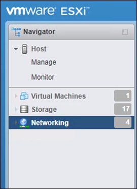
Step 2. In the center pane, select the Virtual switches tab.
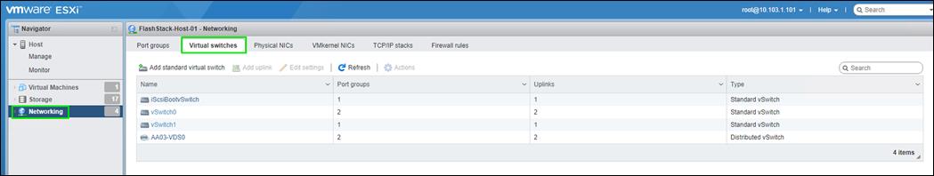
Step 3. Highlight the iScsiBootvSwitch line.
Step 4. Click Edit settings.
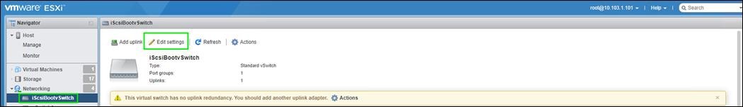
Step 5. Change the MTU to 9000.
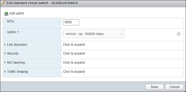
Step 6. Click Save to save the changes to iScsiBootvSwitch.
Step 7. Click vmk1 entry.
Step 8. Click Edit Settings.
Step 9. From Port properties update the MTU value to 9000.
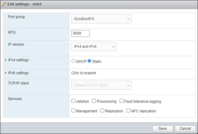
Step 10. Click the IPv4 Settings.
Step 11. Change the IPv4 settings from the iSCSI-A-Pool assigned IP to one that is not in the IP block.
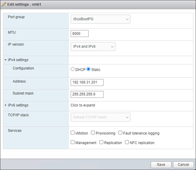
Step 12. Click Save to apply the changes.
Configure iSCSI B vSwitch and VMkernel (Required only for iSCSI boot configuration)
Procedure 1. Configure the iSCSI vSwitch and VMkernel
Step 1. From the Host Client Navigator, click Networking.
Step 2. In the center pane, select the Virtual switches tab.
Step 3. Click Add standard virtual switch.
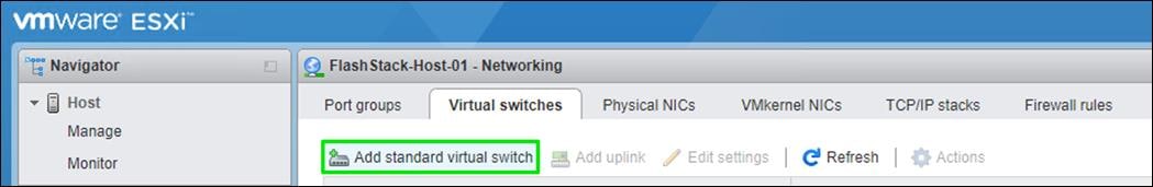
Step 4. Name the switch (Ex: vSwitch1)
Step 5. Change the MTU to 9000.
Step 6. From the drop-down list select vmnic5 for Uplink 1.
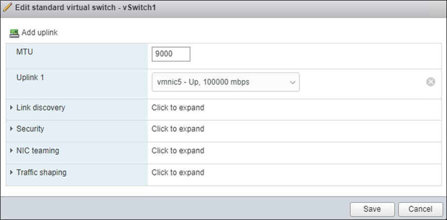
Step 7. Select Add to add vSwitch1.
Step 8. In the center pane, select the VMkernel NICs tab.
Step 9. Click Add VMkernel NIC.
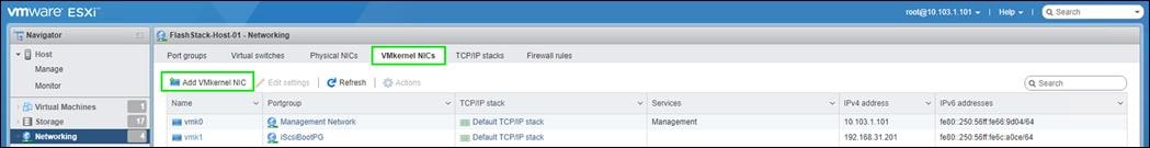
Step 10. For New port group, enter a name (Ex: VMkernel-iSCSI-B).
Step 11. For Virtual switch, use the drop-down list to select vSwitch1.
Step 12. Change the MTU to 9000.
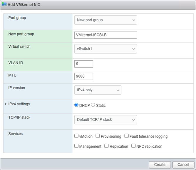
Step 13. For IPv4 settings, select Static.
Step 14. Expand IPv4 Settings and enter a unique IP address in the iSCSI-B subnet but outside of the iSCSI-IP-Pool-B.
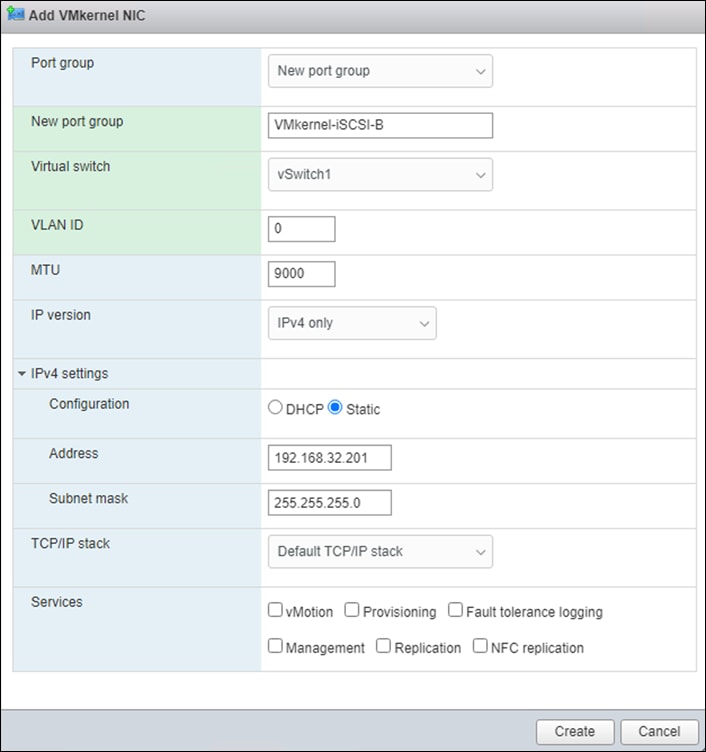
Step 15. Click Create to complete creating the VMkernel NIC.
Step 16. Click Storage, then in the center pane select the Adapters tab.
Step 17. Click Software iSCSI to configure software iSCSI for the host.
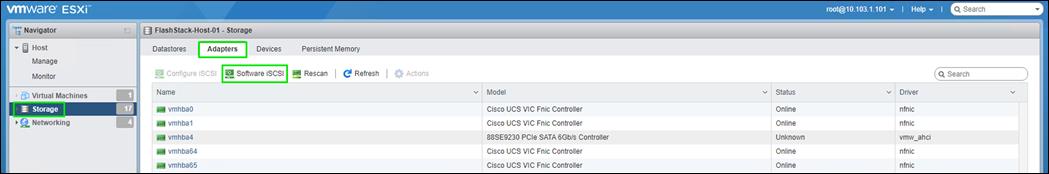
Step 18. In the Configure iSCSI window, under Dynamic targets, click Add dynamic target.
Step 19. Select the address to add and enter the IP address of CT0.eth10 from Pure FlashArray//XL170. Click Return.
Step 20. Repeat steps 1 - 19 to add the IP addresses for CT0.eth11, CT1.eth10 and CT1.eth11.
Step 21. Click Save configuration.
Step 22. Click Software iSCSI to configure software iSCSI for the host.
Step 23. Verify that four static targets and four dynamic targets are listed for the host.
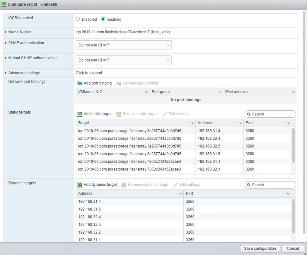
Note: If the host shows an alarm stating that connectivity with the boot disk was lost, place the host in Maintenance Mode and reboot the host.
Procedure 1. Mount the Required Datastores on the first ESXi Host
Step 1. From the Host Client, click Storage.
Step 2. In the center pane, click the Datastores tab.
Step 3. Click New datastore to add a new datastore.
Step 4. In the New datastore, click Create new VMFS datastore and click Next.
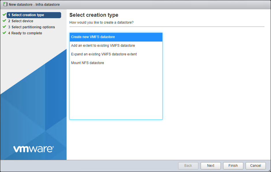 s
s
Step 5. Input Infra-Datastore1 for the datastore name.
Step 6. Select the Pure LUN that will be used for the data store.
Step 7. Click Next.
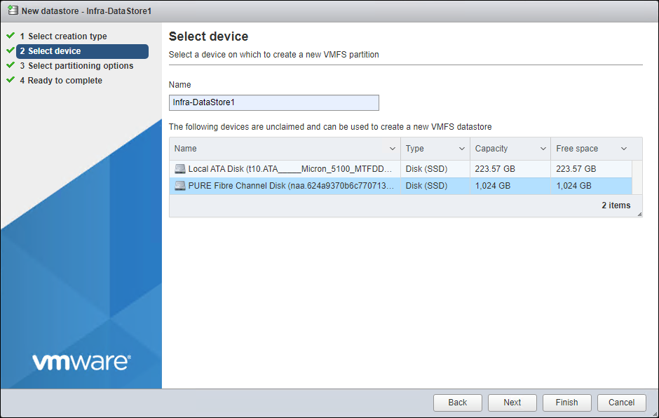
Step 8. Click Next.
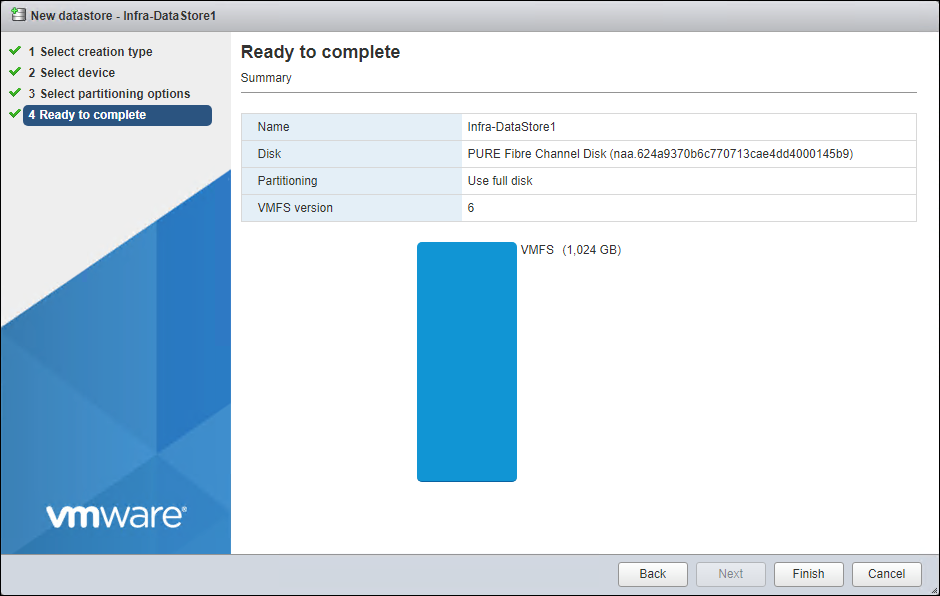
Step 9. Click Finish. The datastore appears in the datastore list.
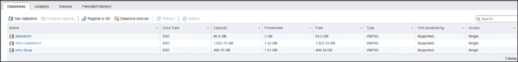
Configure NTP on First ESXi Host (ESXi Host VM-Host-Infra-FCP-01)
Procedure 1. Configure Network Time Protocol (NTP) on the first ESXi Host
Step 1. From the Host Client, click Manage.
Step 2. In the center pane, click System > Time & date.
Step 3. Click Edit NTP settings.
Step 4. Make sure “Manually configure the date and time on this host and enter the approximate date and time.
Step 5. Select Use Network Time Protocol (enable NTP client).
Step 6. Use the drop-down list to select Start and stop with host.
Step 7. Enter the two Cisco Nexus switch NTP addresses in the NTP servers box separated by a comma.
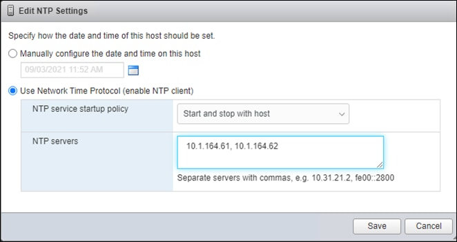
Step 8. Click Save to save the configuration changes.
Note: It currently is not possible to start NTP from the ESXi Host Client. NTP will be started from vCenter. The NTP server time may initially vary slightly from the host time.
Procedure 1. Configure Host Power Policy
Note: Implementation of this policy is recommended in Performance Tuning Guide for Cisco UCS M6 Servers: https://www.cisco.com/c/en/us/products/collateral/servers-unified-computing/ucs-b-series-blade-servers/performance-tuning-guide-ucs-m6-servers.html for maximum VMware ESXi performance. This policy can be adjusted based on customer requirements.
Step 1. From the Web Navigator, click Manage.
Step 2. In the center pane, click Hardware > Power Management.
Step 3. Click Change policy.
Step 4. Select High performance and click OK.
VMware vCenter 7.0 U3 Configuration
The procedures in the following subsections provide detailed instructions for installing the VMware vCenter 7.0U3 Server Appliance in a FlashStack environment. After the procedures are completed, a VMware vCenter Server will be configured.
Procedure 1. Build the VMware vCenter Server Appliance
The VCSA deployment consists of 2 stages: install and configuration.
Step 1. Click this link: https://customerconnect.vmware.com/downloads/details?downloadGroup=VC70U3H&productId=974&rPId=95488 and download the VMware-VCSA-all-7.0.3-20395099.iso.
Note: It is important to use at minimum VMware vCenter release 7.0U3 to ensure access to all needed features.
Step 2. Using ISO mounting software, mount the ISO image as a disk on the management workstation. (For example, with the Mount command in Windows Server 2012 and above).
Step 3. In the mounted disk directory, navigate to the vcsa-ui-installer > win32 directory and double-click installer.exe. The vCenter Server Appliance Installer wizard appears.
Step 4. Click Install to start the vCenter Server Appliance deployment wizard.
Step 5. Click NEXT in the Introduction section.
Step 6. Read and accept the license agreement and click NEXT.
Step 7. In the “vCenter Server deployment target” window, enter the host name or IP address of the first ESXi host, User name (root), and Password. Click NEXT.
Step 8. Click YES to accept the certificate.
Step 9. Enter the Appliance VM name and password details in the “Set up vCenter Server VM” section. Click NEXT.
Step 10. In the “Select deployment size” section, select the Deployment size and Storage size. For example, select “Small” and “Default.” Click NEXT.
Step 11. Select Infra-DataStore1 for storage. Click NEXT.
Step 12. In the “Network Settings” section, configure the following settings:
a. Select a Network: IB-MGMT Network.
Note: It is important that the vCenter VM stay on the IB-MGMT Network on vSwitch0 and that it isn’t moved to a vDS. If vCenter is moved to a vDS and the virtual environment is completely shut down and then brought back up, and it is attempted to bring up vCenter on a different host than the one it was running on before the shutdown, vCenter will not have a functional network connection. With the vDS, for a virtual machine to move from one host to another, vCenter must be up and running to coordinate the move of the virtual ports on the vDS. If vCenter is down, the port move on the vDS cannot occur correctly. Moving vCenter to a different host on vSwitch0 to be brought up always occurs correctly without requiring vCenter to already be up and running.
b. IP version: IPV4
c. IP assignment: static
d. FQDN: <vcenter-fqdn>
e. IP address: <vcenter-ip>
f. Subnet mask or prefix length: <vcenter-subnet-mask>
g. Default gateway: <vcenter-gateway>
h. DNS Servers: <dns-server1>,<dns-server2>
Step 13. Click NEXT.
Step 14. Review all values and click FINISH to complete the installation.
Note: The vCenter Server appliance installation will take a few minutes to complete.
Step 15. Click CONTINUE to proceed with stage 2 configuration.
Step 16. Click NEXT.
Step 17. In the vCenter Server configuration window, configure these settings:
a. Time Synchronization Mode: Synchronize time with NTP servers.
b. NTP Servers: <nexus-a-ntp-ip>,<nexus-b-ntp-ip>
c. SSH access: Enabled.
Step 18. Click NEXT.
Step 19. Complete the SSO configuration as shown below, or according to your organization’s security policies:
Step 20. Click NEXT.
Step 21. Decide whether to join VMware’s Customer Experience Improvement Program (CEIP).
Step 22. Click NEXT.
Step 23. Review the configuration and click FINISH.
Step 24. Click OK.
Note: vCenter Server setup will take a few minutes to complete.
Step 25. Click CLOSE. Eject or unmount the VCSA installer ISO.
If a vCenter deployment size of Small or larger was selected in the vCenter setup, it is possible that the VCSA’s CPU setup does not match the Cisco UCS server CPU hardware configuration. Cisco UCS B and C-Series servers are normally 2-socket servers. In this validation, the Small deployment size was selected and vCenter was setup for a 4-socket server. This setup will cause issues in the VMware ESXi cluster Admission Control. To resolve the Admission Control issue, follow these steps:
Procedure 1. Resolve the Admission Control
Step 1. Open a web browser on the management workstation and navigate to the VM-Host-Infra-FCP-01 management IP address.
Step 2. Enter root for the user name.
Step 3. Enter the root password.
Step 4. Click Login to connect.
Step 5. On the left, click Select.
Step 6. In the center pane, right-click the vCenter VM and click Edit settings.
Step 7. In the Edit settings window, expand CPU and check the value of Sockets.
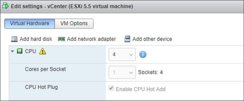
Step 8. If the number of Sockets does not match your server configuration, it will need to be adjusted. Click Cancel.
Step 9. If the number of Sockets needs to be adjusted:
a. Right-click the vCenter VM and click Guest OS > Shut down. Click Yes on the confirmation.
b. Once vCenter is shut down, right-click the vCenter VM and click Edit settings.
c. In the Edit settings window, expand CPU and change the Cores per Socket value to make the Sockets value equal to your server configuration (normally 2).
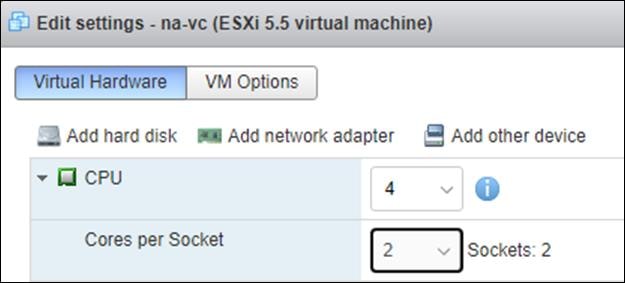
d. Click Save.
e. Right-click the vCenter VM and click Power > Power on. Wait approximately 10 minutes for vCenter to come up.
Procedure 1. Set up the VMware vCenter Server
Step 1. Using a web browser, navigate to https://<vcenter-ip-address>:5480. You will need to navigate security screens.
Step 2. Log into the VMware vCenter Server Management interface as root with the root password set in the vCenter installation.
Step 3. In the menu on the left, click Time.
Step 4. Click EDIT to the right of Time zone.
Step 5. Select the appropriate Time zone and click SAVE.
Step 6. In the menu select Administration.
Step 7. According to your Security Policy, adjust the settings for the root user and password.
Step 8. In the menu on the left click Update.
Step 9. Follow the prompts to STAGE AND INSTALL any available vCenter updates. In this validation, vCenter version 7.0.3 was installed.
Step 10. In the upper right-hand corner of the screen, click root > Logout to logout of the Appliance Management interface.
Step 11. Using a web browser, navigate to https://<vcenter-fqdn>. You will need to navigate security screens.
Note: With VMware vCenter 7.0, the use of the vCenter FQDN is required.
Step 12. Click LAUNCH VSPHERE CLIENT (HTML5).
Note: Although the previous versions of this document used the FLEX vSphere Web Client, the VMware vSphere HTML5 Client is the only option starting with vSphere 7 and will be used going forward.
Step 13. Log in using the Single Sign-On username (administrator@vsphere.local) and password created during the vCenter installation. Dismiss the Licensing warning currently.
Step 14. In the center pane, click ACTIONS > New Datacenter.
Step 15. Type “FlashStack-DC” in the Datacenter name field.
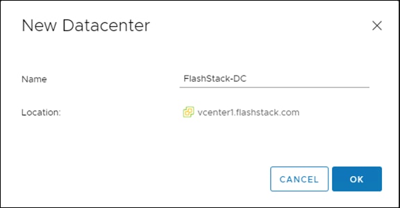
Step 16. Click OK.
Step 17. Expand the vCenter on the left.
Step 18. Right-click the datacenter FlashStack-DC in the list in the left pane. Click New Cluster.
Step 19. Name the cluster FlashStack-Management.
Step 20. Turn on DRS and vSphere HA. Do not turn on vSAN.
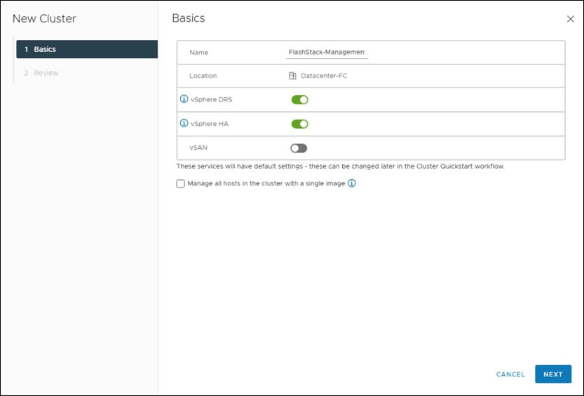
Step 21. Click OK to create the new cluster.
Step 22. Right-click “FlashStack-Management” and click Settings.
Step 23. Click Configuration > General in the list located on the left and select EDIT located on the right of General.
Step 24. Select Datastore specified by host and click OK.
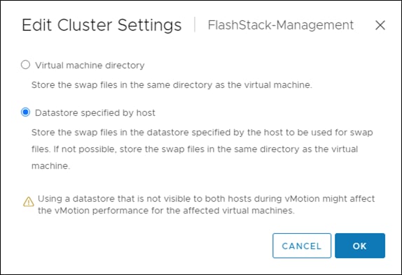
Step 25. Right-click “FlashStack-Management” and click Add Hosts.
Step 26. In the IP address or FQDN field, enter either the IP address or the FQDN of the first VMware ESXi host. Enter root as the Username and the root password. Click NEXT.
Step 27. In the Security Alert window, select the host and click OK.
Step 28. Verify the Host summary information and click NEXT.
Step 29. Ignore warnings about the host being moved to Maintenance Mode and click FINISH to complete adding the host to the cluster.
Note: The added ESXi host will have Warnings that the ESXi Shell and SSH have been enabled. These warnings can be suppressed.
Step 30. In the list, right-click the added ESXi host and select Settings.
Step 31. In the center pane under Virtual Machines, click Swap File location.
Step 32. On the right, click EDIT.
Step 33. Select the Infra-Swap datastore and click OK.
Step 34. In the list under System, select Time Configuration.
Step 35. Click EDIT to the right of Manual Time Configuration. Set the time and date to the correct local time and click OK.
Step 36. Click EDIT to the right of Network Time Protocol.
Step 37. In the Edit Network Time Protocol window, select Enable and then select Start NTP Service. Ensure the other fields are filled in correctly and click OK.
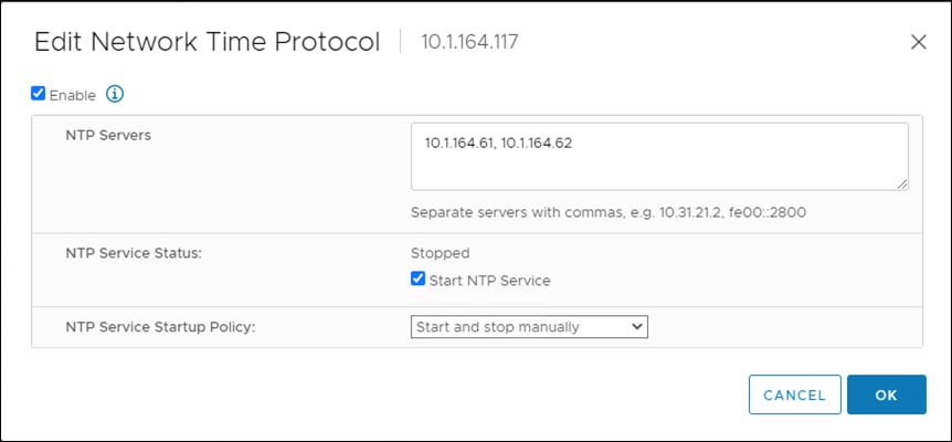
Step 38. In the list under Hardware, select Overview. Scroll to the bottom and ensure the Power Management Active policy is High Performance. If the Power Management Active policy is not High Performance, to the right of Power Management, select EDIT POWER POLICY. Select High performance and click OK.
Step 39. In the list under Storage, select Storage Devices. Make sure the Pure Fibre Channel Disk LUN 1 or Pure iSCSI Disk LUN 1 is selected.
Step 40. Select the Paths tab.
Step 41. Ensure that 4 paths appear, which should have the status Active (I/O).
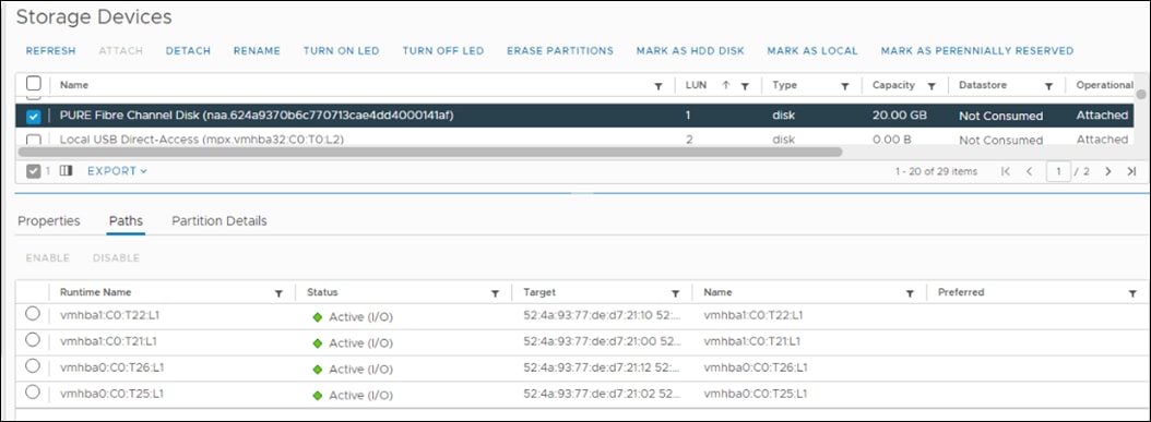
Add AD User Authentication to vCenter (Optional)
If an AD Infrastructure is set up in this FlashStack environment, you can set up in AD and authenticate from vCenter.
Procedure 1. Add an AD User Authentication to the vCenter
Step 1. In the AD Infrastructure, using the Active Directory Users and Computers tool, setup a Domain Administrator user with a user name such as flashadmin (FlashStack Admin).
Step 2. Connect to https://<vcenter-ip> and click LAUNCH VSPHERE CLIENT (HTML5).
Step 3. Log in as Administrator@vsphere.local (or the SSO user set up in vCenter installation) with the corresponding password.
Step 4. Under Menu, click Administration. In the list on the left, under Single Sign On, click Configuration.
Step 5. In the center pane, under Configuration, click the Identity Provider tab.
Step 6. In the list under Type, select Active Directory Domain.
Step 7. Click JOIN AD.
Step 8. Fill in the AD domain name, the Administrator user, and the domain Administrator password. Do not fill in an Organizational unit. Click JOIN.
Step 9. Click Acknowledge.
Step 10. In the list on the left under Deployment, select System Configuration. Select the radio button to select the vCenter, then click REBOOT NODE.
Step 11. Input a reboot reason and click OK. The reboot will take approximately 10 minutes for full vCenter initialization.
Step 12. Log back into the vCenter vSphere HTML5 Client as Administrator@vsphere.local.
Step 13. Under Menu, select Administration. In the list on the left, under Single Sign On, click Configuration.
Step 14. In the center pane, under Configuration, select the Identity Provider tab. Under Type, select Identity Sources. Click ADD.
Step 15. Make sure your Active Directory (Integrated Windows Authentication) is selected, your Windows Domain name is listed, and Use machine account is selected. Click ADD.
Step 16. In the list select the Active Directory (Integrated Windows Authentication) Identity source type. If desired, select SET AS DEFAULT and click OK.
Step 17. On the left under Access Control, select Global Permissions.
Step 18. In the center pane, click the + sign to add a Global Permission.
Step 19. In the Add Permission window, select your AD domain for the Domain.
Step 20. On the User/Group line, enter either the FlashStack Admin username or the Domain Admins group. Leave the Role set to Administrator. Select the Propagate to children checkbox.
Note: The FlashStack Admin user was created in the Domain Admins group. The selection here depends on whether the FlashStack Admin user will be the only user used in this FlashStack or you would like to add other users later. By selecting the Domain Admins group, any user placed in that group in the AD domain will be able to login to vCenter as an Administrator.
Step 21. Click OK to add the selected User or Group. The user or group should now appear in the Global Permissions list with the Administrator role.
Step 22. Log out and log back into the vCenter HTML5 Client as the FlashStack Admin user. You will need to add the domain name to the user, for example, flashadmin@domain.
FlashStack VMware vSphere Distributed Switch (vDS)
This section provides detailed procedures for installing the VMware vDS in vCenter and on the first FlashStack ESXi Management Host.
In the Cisco UCS setup section of this document two sets of vNICs were setup. The vmnic ports associated with the vDS0-A and B vNICs will be placed on the VMware vDS in this procedure. The vMotion VMkernel port(s) will be placed on the vDS.
A vMotion, and a VM-Traffic port group will be added to the vDS. Any additional VLAN-based port groups added to the vDS would need to have the corresponding VLANs added to the Cisco UCS LAN cloud, to the Cisco UCS vDS0-A and B vNIC templates, and to the Cisco Nexus 9K switches and vPC peer-link interfaces on the switches.
In this document, the infrastructure ESXi management VMkernel ports, the In-Band management interfaces including the vCenter management interface are left on vSwitch0 to facilitate bringing the virtual environment back up in the event it needs to be completely shut down. The vMotion VMkernel ports are moved to the vDS to allow QoS marking of vMotion to be done at the VLAN level in the vDS if vMotion needs to have QoS policies applied in the future. The vMotion port group is also pinned to Cisco UCS fabric B. Pinning should be done in a vDS to ensure consistency across all ESXi hosts.
Configure the VMware vDS in vCenter for the VMware vSphere Web Client
Procedure 1. Configure the vDS
Step 1. After logging into the VMware vSphere HTML5 Client, select Networking under Menu.
Step 2. Right-click the FlashStack-DC datacenter and click Distributed Switch > New Distributed Switch.
Step 3. Give the Distributed Switch a descriptive name (vDS0) and click NEXT.
Step 4. Make sure version 7.0.2 – ESXi 7.0.3 and later is selected and click NEXT.
Step 5. Change the Number of uplinks to 2. If VMware Network I/O Control is to be used for Quality of Service, leave Network I/O Control Enabled. Otherwise, Disable Network I/O Control. Enter VM-Traffic for the Port group name. Click NEXT.
Step 6. Review the information and click FINISH to complete creating the vDS.
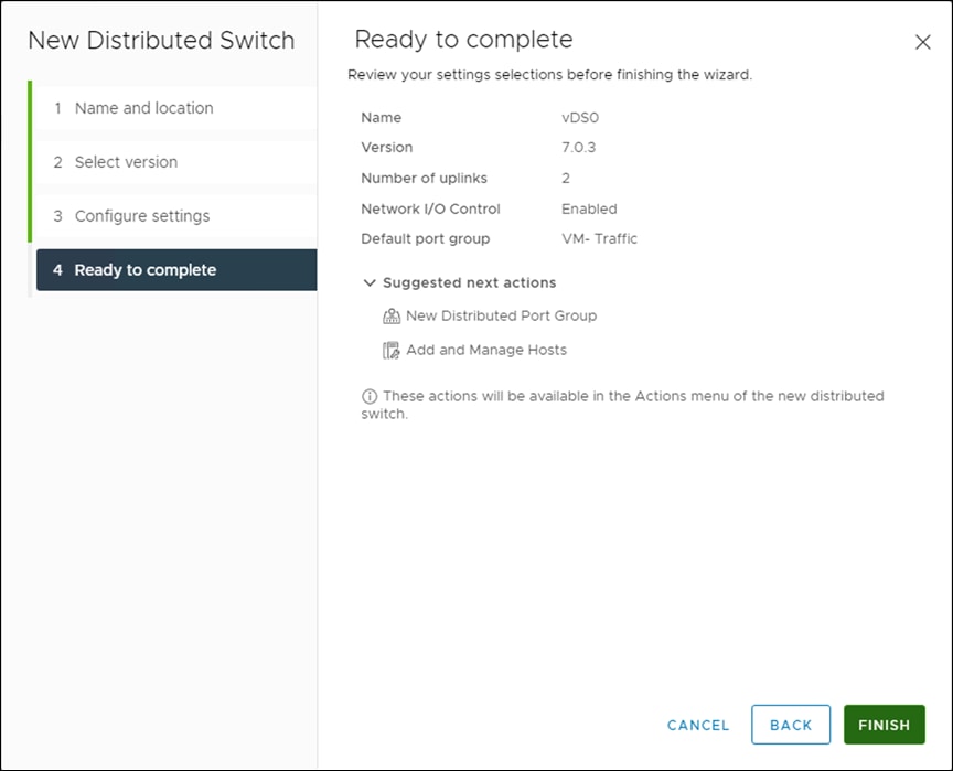
Step 7. Expand the FlashStack-DC datacenter and the newly created vDS. Select the newly created vDS.
Step 8. Right-click the VM-Traffic port group and click Edit Settings.
Step 9. Click VLAN.
Step 10. Select VLAN for VLAN type and enter the VM-Traffic VLAN ID. Click OK.
Step 11. Right-click the vDS and click Settings > Edit Settings.
Step 12. In the Edit Settings window, click Advanced.
Step 13. Change the MTU to 9000. The Discovery Protocol can optionally be changed to Link Layer Discovery Protocol and the Operation to Both. Click OK.
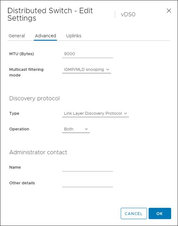
Step 14. For the vMotion port group, right-click the vDS, select Distributed Port Group, and select New Distributed Port Group.
Step 15. Enter VMkernel-vMotion as the name and click NEXT.
Step 16. Set the VLAN type to VLAN, enter the VLAN ID used for vMotion, click the Customize default policies configuration check box, and click NEXT.
Step 17. Leave the Security options set to Reject and click NEXT.
Step 18. Leave the Ingress and Egress traffic shaping options as Disabled and click NEXT.
Step 19. Select Uplink 1 from the list of Active uplinks and click the move down tab twice to place Uplink 1 in the list of Standby uplinks. This will pin all vMotion traffic to Cisco UCS Fabric Interconnect B except when a failure occurs.
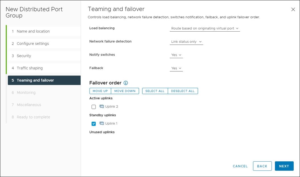
Step 20. Click NEXT.
Step 21. Leave NetFlow disabled and click NEXT.
Step 22. Leave Block all ports set as No and click NEXT.
Step 23. Confirm the options and click FINISH to create the port group.
Step 24. Right-click the vDS and select Add and Manage Hosts.
Step 25. Make sure Add hosts is selected and click NEXT.
Step 26. Click the + sign to add New hosts. Select the FlashStack ESXi hosts and click OK. Click NEXT.
Step 27. Select vmnic2 and click Assign uplink. Select Uplink 1 and click OK. Select vmnic3 and click Assign uplink. Select Uplink 2 and click OK. If more than one host is being connected to the vDS, use the Apply this uplink assignment to the rest of the hosts checkbox.
Note: It is important to assign the uplinks as shown below. This allows the port groups to be pinned to the appropriate Cisco UCS fabric.
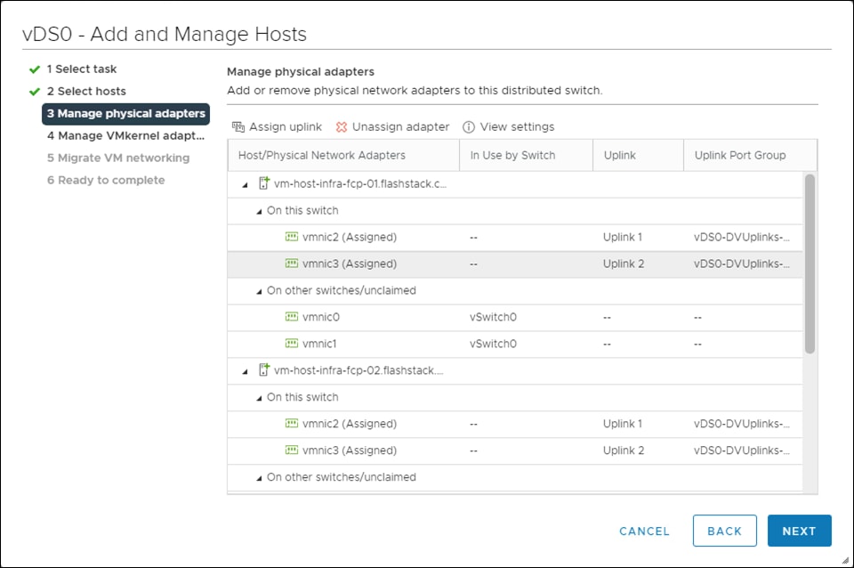
Step 28. Click NEXT.
Step 29. Do not migrate any VMkernel ports and click NEXT.
Step 30. Do not migrate any virtual machine networking ports. Click NEXT.
Step 31. Click FINISH to complete adding the ESXi host(s) to the vDS.
Add the vMotion VMkernel Port(s) to the ESXi Host
Procedure 1. Add the vMotion VMkernel Port to the ESXi Host(s) on the VMware vDS
Step 1. In the vCenter HTML5 Interface, under Hosts and Clusters select the ESXi host.
Step 2. In the center pane, click the Configure tab.
Step 3. In the list under Networking, select VMkernel adapters.
Step 4. Select Add Networking to Add host networking.
Step 5. Make sure VMkernel Network Adapter is selected and click NEXT.
Step 6. Click BROWSE to the right of Select an existing network.
Step 7. Select vMotion on the vDS and click OK.
Step 8. Click NEXT.
Step 9. Make sure the Network label is vMotion with the vDS in parenthesis. From the drop-down list, select Custom for MTU and make sure the MTU is set to 9000. Select the vMotion TCP/IP stack and click NEXT.
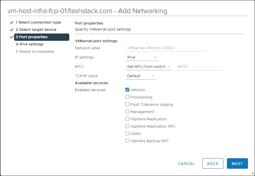
Step 10. Click Use static IPv4 settings and input the host’s vMotion IPv4 address and Subnet mask.
Step 11. Click NEXT.
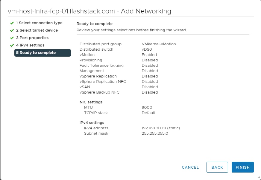
Step 12. Review the parameters and click FINISH to add the vMotion VMkernel port.
Add and configure a VMware ESXi Host in vCenter
This section details the steps to add and configure an ESXi host in vCenter. This section assumes the host has had VMware ESXi 7.0 U3 installed, the management IP address set, the nfnic driver updated and the Cisco UCS Tool installed. This procedure is initially being run on the second and third ESXi management hosts but can be run on any added ESXi host.
Procedure 1. Add the ESXi Hosts to vCenter
Step 1. From the Home screen in the VMware vCenter HTML5 Interface, click Menu > Hosts and Clusters.
Step 2. Right-click the “FlashStack-Management” cluster and click Add Hosts.
Step 3. In the IP address or FQDN field, enter either the IP address or the FQDN name of the configured VMware ESXi host. Also enter the user id (root) and associated password. If more than one host is being added, add the corresponding host information, optionally selecting “Use the same credentials for all hosts.” Click NEXT.
Step 4. Select all hosts you need to add and click OK to accept the certificate(s).
Step 5. Review the host details and click NEXT to continue.
Step 6. Review the configuration parameters and click FINISH to add the host(s).
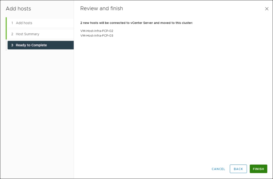
The added ESXi host(s) will be placed in Maintenance Mode and will have Warnings that the ESXi Shell and SSH have been enabled. These warnings can be suppressed.
This procedure details the steps to add iSCSI configuration to an ESXi host added and configured in vCenter. This section assumes the host has been added to vCenter and the basic networking completed, and the time configuration and swap files added.
Step 1. In the vSphere HTML5 Client, under Hosts and Clusters, select the ESXi host.
Step 2. In the center pane, click Configure. In the list under Networking, select Virtual switches.
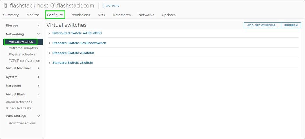
Step 3. In the center pane, expand iScsiBootvSwitch. Click Edit to edit settings for the vSwitch.
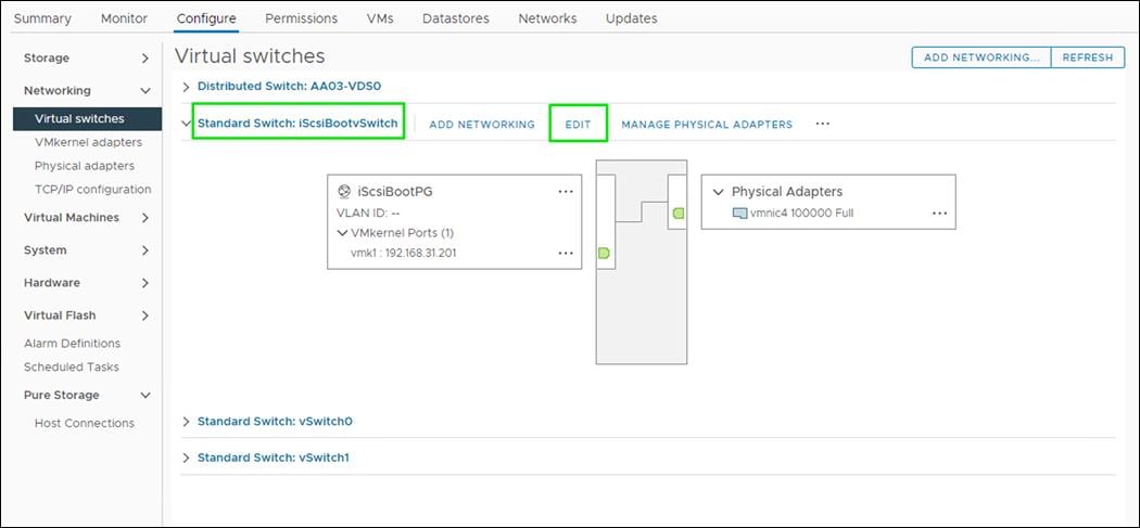
Step 4. Change the MTU to 9000 and click OK.
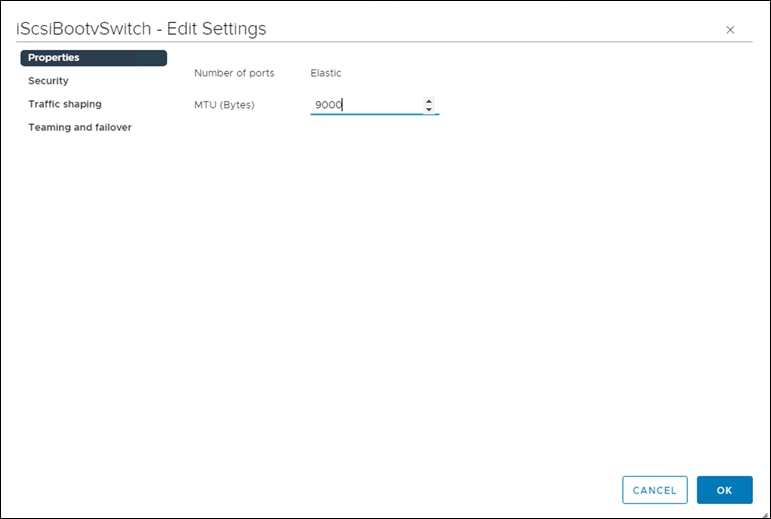
Step 5. Select … > Edit Settings to the right of the VMkernel Port IP address.
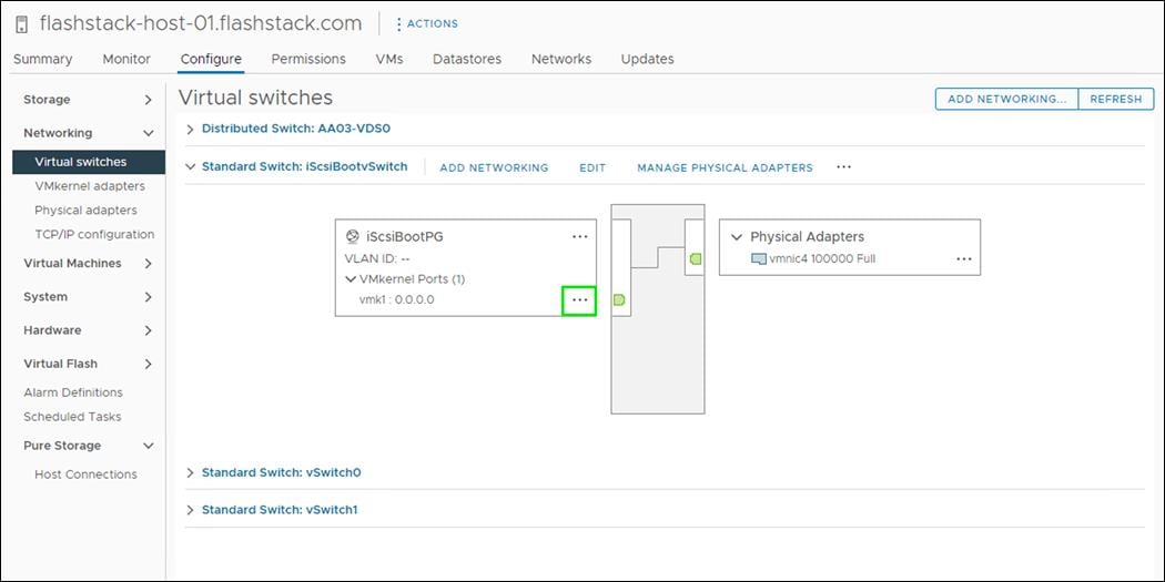
Step 6. Change the MTU to 9000.
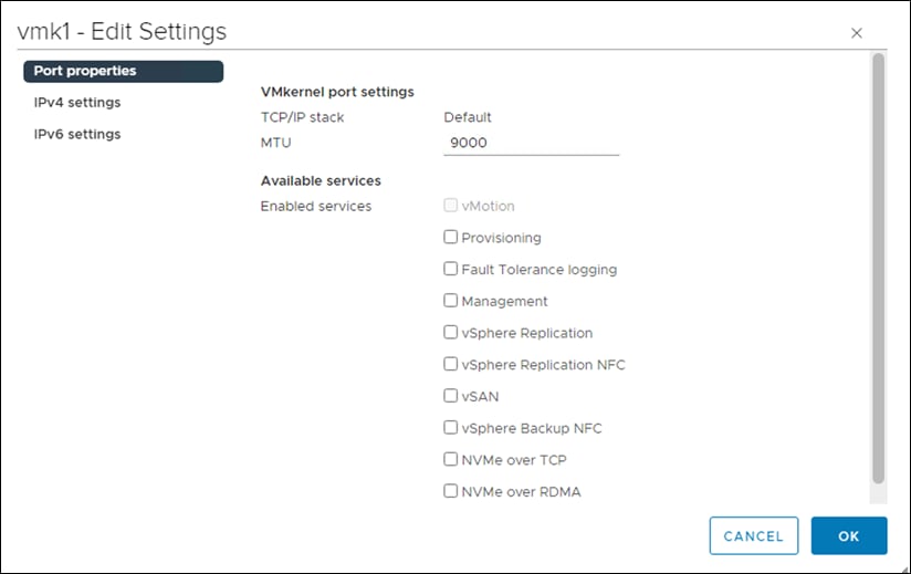
Step 7. Click IPv4 settings on the left. Change the IP address to a unique IP address in the Infra-iSCSI-A subnet but outside of the Cisco UCS iSCSI-IP-Pool-A.
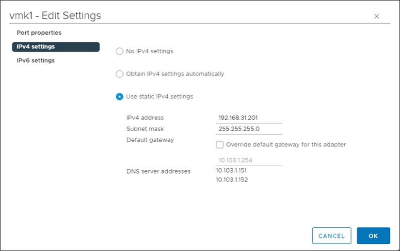
Note: It is recommended to enter a unique IP address for this VMkernel port to avoid any issues related to IP Pool reassignments.
Step 8. Click OK.
Step 9. In the upper right-hand corner, select ADD NETWORKING to add another vSwitch.
Step 10. Make sure VMkernel Network Adapter is selected and click NEXT.
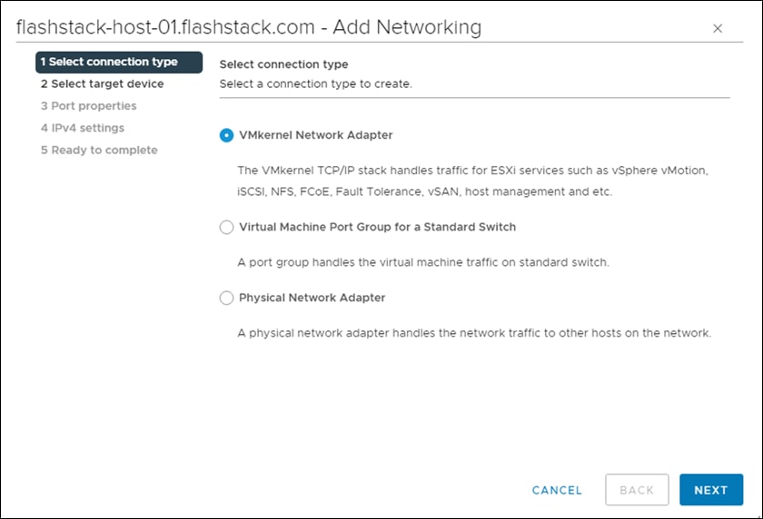
Step 11. Select New standard switch and change the MTU to 9000. Click NEXT.
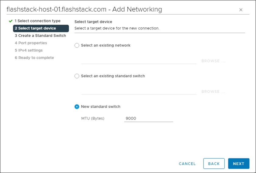
Step 12. Click ![]() to add an adapter. Make sure vmnic5 is highlighted and click OK. vmnic5 should now be under Active adapters. Click OK.
to add an adapter. Make sure vmnic5 is highlighted and click OK. vmnic5 should now be under Active adapters. Click OK.
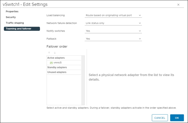
Step 13. Enter a name for the Network label (for example, vSwitch1). Leave VLAN ID set to None (0), select Custom – 9000 for MTU, and click NEXT.
Step 14. Select Use static IPv4 settings. Enter a unique IP address and netmask in the Infra-iSCSI-B subnet but outside of the Cisco UCS iSCSI-IP-Pool-B. Click NEXT.
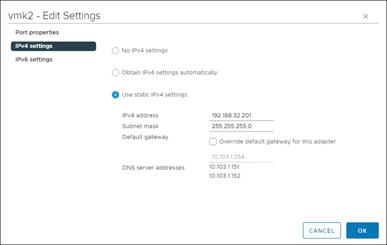
Step 15. Click FINISH to complete creating the vSwitch and the VMkernel port.
Step 16. In the list under Storage, select Storage Adapters.
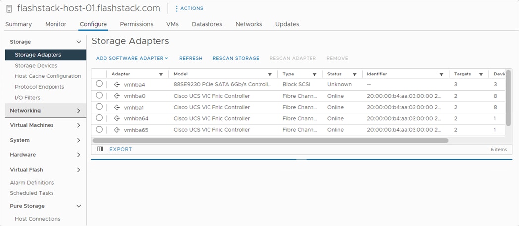
Step 17. Select the iSCSI Software Adapter and select the Dynamic Discovery tab.
Step 18. Click Add.
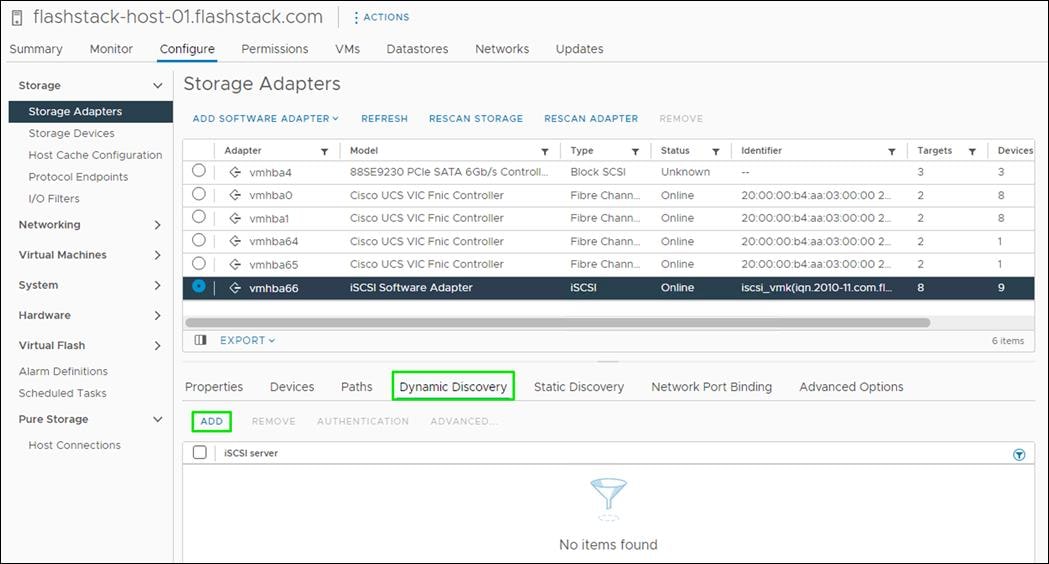
Step 19. Enter the IP address of the pure FlashArray storage controller’s CT0.eth10 and click OK.
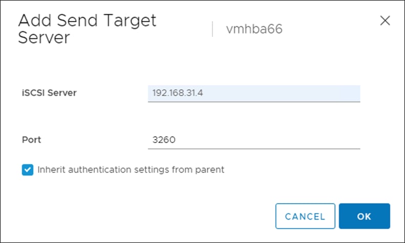
Step 20. Repeat steps 1- 19 to add the IPs for CT0.eth11, CT1.eth10, and CT1.eth11.
Step 21. From Storage Adapters, click Rescan Adapter to rescan the iSCSI Software Adapter.
Under Static Discovery, four static targets are listed.
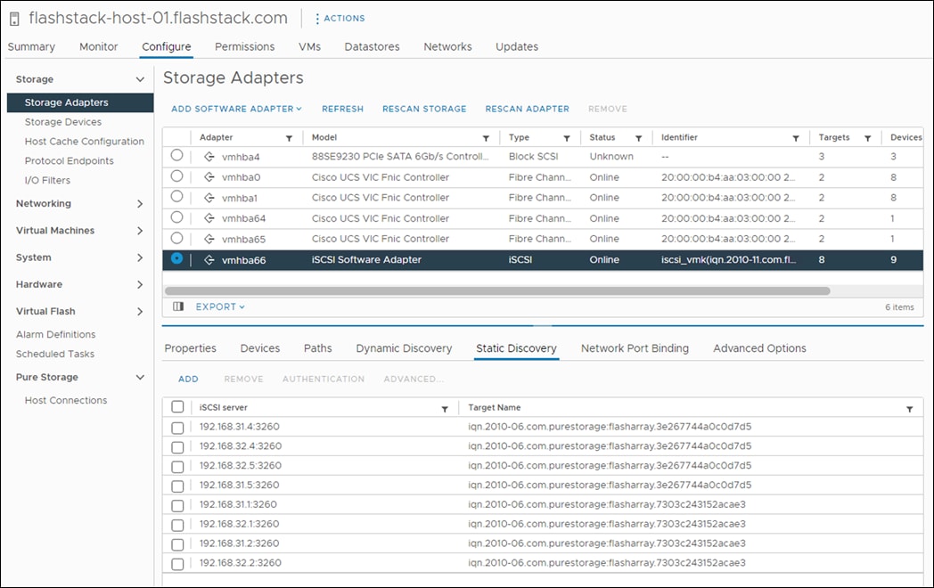
Under Paths, four paths should now be listed with all paths having the “Active (I/O)” Status.
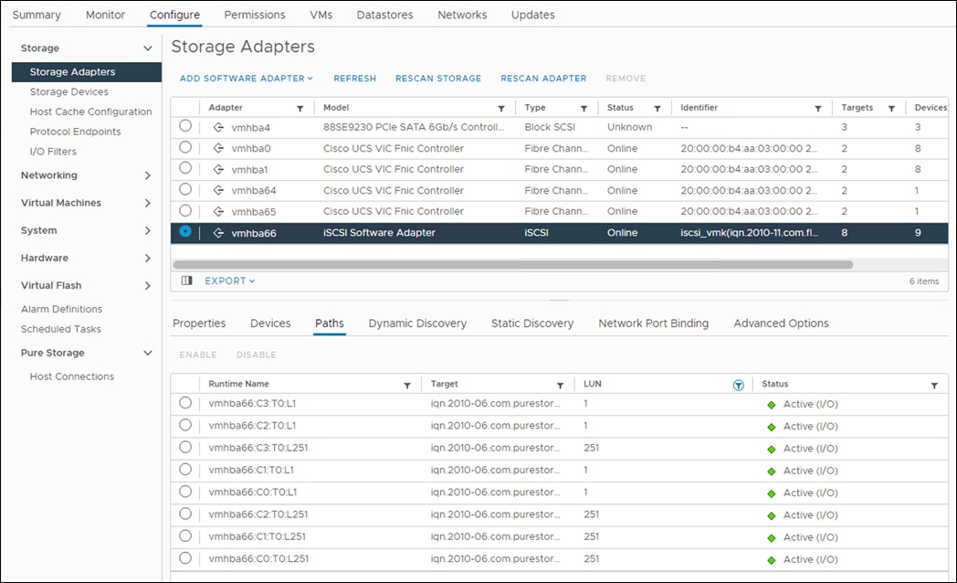
Procedure 3. Set Up VMkernel Ports and Virtual Switch for the ESXi Host VM-Host-Infra-FCP-02 and VM-Host-Infra-FCP-03
Step 1. In the vCenter HTML5 Interface, under Hosts and Clusters select the ESXi host.
Step 2. In the center pane, select the Configure tab.
Step 3. In the list, select Virtual switches under Networking.
Step 4. Expand Standard Switch: vSwitch0.
Step 5. Select EDIT to Edit settings.
Step 6. Change the MTU to 9000.
Step 7. Select Teaming and failover located on the left.
Step 8. In the Failover order section, use the arrow icons to move the vmnics until both are Active adapters.
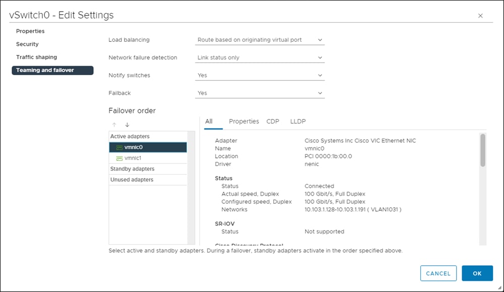
Step 9. Click OK.
Step 10. In the center pane, to the right of VM Network click … > Remove to remove the port group. Click YES on the confirmation.
Step 11. Click ADD NETWORKING to add a new VM port group.
Step 12. Select Virtual Machine Port Group for a Standard Switch and click NEXT.
Step 13. Ensure vSwitch0 is shown for Select an existing standard switch and click NEXT.
Step 14. Name the port group “IB-MGMT Network” and leave the VLAN ID field set to None (0). Click NEXT.
Note: In the Cisco UCS section of this document, the IB-MGMT VLAN was set as the native VLAN for the vSwitch0 vNIC templates, allowing DHCP to be used on ESXi vmk0 without putting in a VLAN ID for this port. Since this port group is in the same VLAN, the port group’s VLAN ID should also be set to 0.
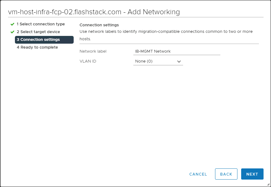
Step 15. Click FINISH to complete adding the IB-MGMT Network VM port group.
Step 16. Click ADD NETWORKING to add a new VM port group.
Step 17. Select Virtual Machine Port Group for a Standard Switch and click NEXT.
Step 18. Ensure vSwitch0 is shown for Select an existing standard switch and click NEXT.
Step 19. Name the port group “OOB-MGMT Network” and input <OOB-MGMT-vlan-id> for the VLAN ID field. Click NEXT.
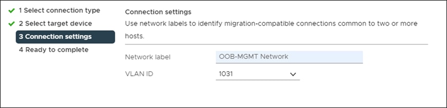
Step 20. Click FINISH to complete adding the OOB-MGMT Network VM port group.
Step 21. Under Networking, select Virtual switches. Expand vSwitch0. The properties for vSwitch0 should be like the following example:
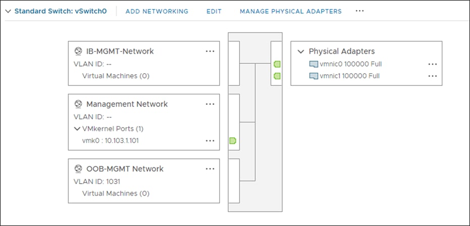
Step 22. Repeat steps 1-21 for all hosts being added.
Mount Required Datastores for the ESXi Host VM-Host-Infra-FCP-02 and VM-Host-Infra-FCP-03
Procedure 1. Mount the Required Datastores
Step 1. From the vCenter Home screen, click Menu > Storage.
Step 2. Expand FlashStack-DC.
Step 3. Located on the left, right-click Infra-DataStore1 and select Mount Datastore to Additional Hosts.
Step 4. Select the ESXi host(s) and click OK.
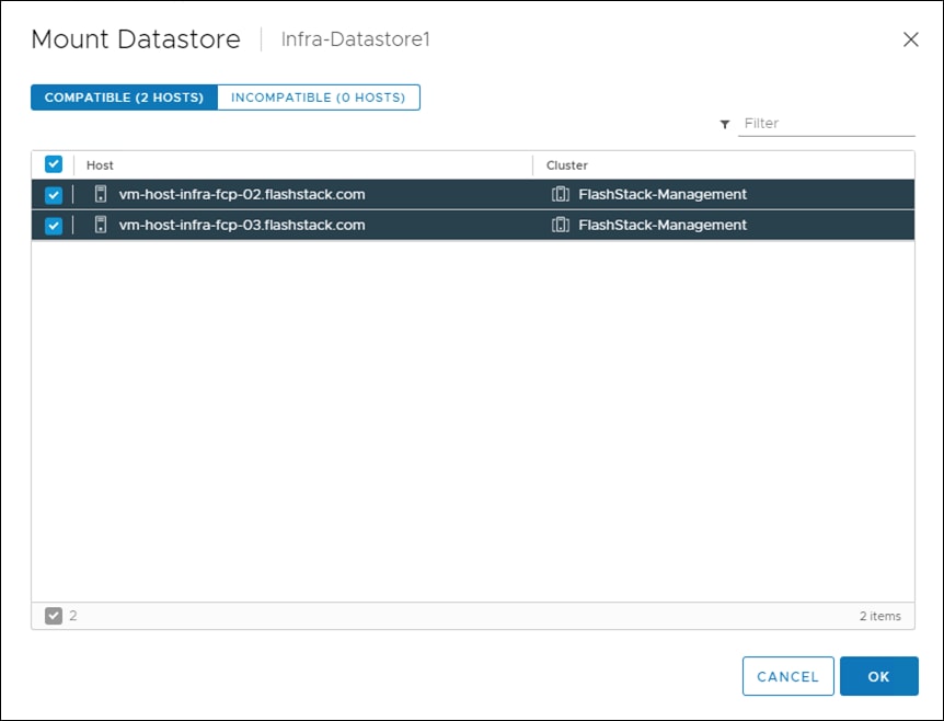
Step 5. Repeat steps 1-4 to mount the Infra-Swap datastore to the ESXi host(s).
Step 6. Select Infra-DataStore1. In the center pane, select Hosts. Verify the ESXi host(s) now has the datastore mounted. Repeat this process to also verify that Infra-Swap is also mounted.
Procedure 2. Configure Network Time Protocol (NTP) on the ESXi Host(s)
Step 1. In the vCenter HTML5 Interface, under Hosts and Clusters select the ESXi host.
Step 2. In the center pane, select the Configure tab.
Step 3. In the list under System, select Time Configuration.
Step 4. To the right of Manual Time Configuration, click EDIT.
Step 5. Set the correct local time and click OK.
Step 6. To the right of Network Time Protocol, click EDIT.
Step 7. Select the Enable checkbox.
Step 8. Enter the two Nexus switch NTP IP addresses in the NTP servers box separated by a comma.
Step 9. Click the Start NTP Service checkbox.
Step 10. Use the drop-down list to select Start and stop with host.
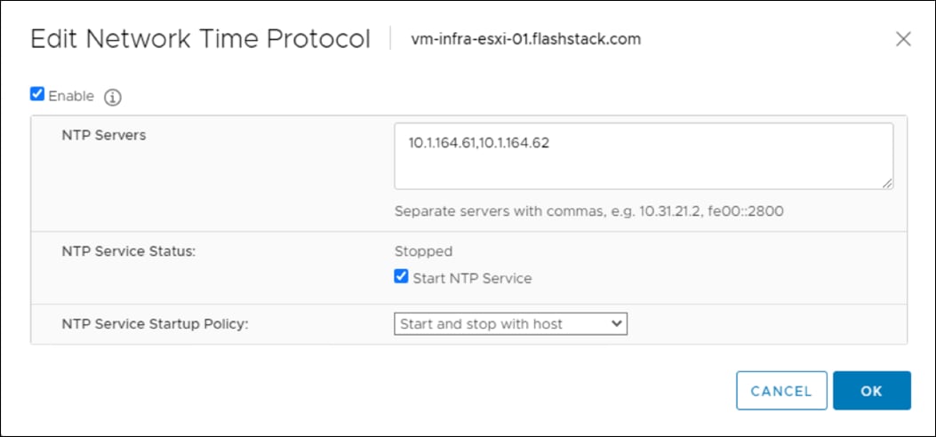
Step 11. Click OK to save the configuration changes.
Step 12. Verify that NTP service is now enabled and running, and the clock is now set to approximately the correct time.
Change ESXi Power Management Policy for Cisco UCS M6 Hosts for the ESXi Host VM-Host-Infra-02 and VM-Host-Infra-03
Procedure 1. Change the ESXi Power Management Policy for the Cisco UCS M6 Hosts
Note: Implementation of this policy is recommended in Performance Tuning for Cisco UCS M6 Server with Intel 3rd Gen Processors for maximum performance. If your organization has specific power policies, please set this policy accordingly.
Step 1. In the list under Hardware, select Overview. Scroll to the bottom and to the right of Power Management, select EDIT POWER POLICY.
Step 2. Select High performance and click OK.
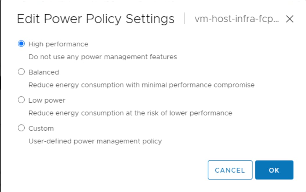
Procedure 2. Check ESXi Host Fibre Channel Pathing for the ESXi Host VM-Host-Infra-FCP-02 and VM-Host-Infra-FCP-03
For the fibre channel SAN-booted ESXi hosts, ensure that the host(s) boot disk contains all required fibre channel paths.
Step 1. In the list under Storage, select Storage Devices. Make sure the Pure FlashArray Fibre Channel Disk is selected.
Step 2. Select the Paths tab.
Step 3. Ensure that 4 fibre channel paths appear, all four should have the status Active (I/O).
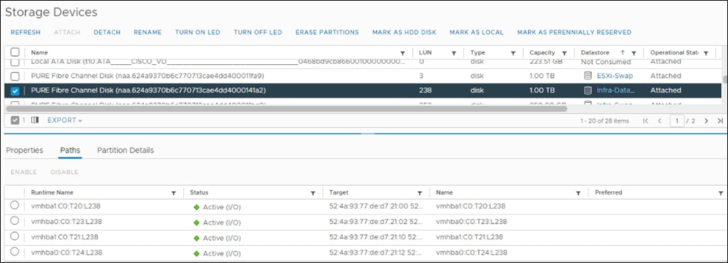
Procedure 3. Add the ESXi Host(s) to the VMware Virtual Distributed Switch to the ESXi Host VM-Host-Infra-FCP-02 and VM-Host-Infra-FCP-03
Follow this procedure if there are hosts to be added to vDS, skip if already added earlier.
Step 1. After logging into the VMware vSphere HTML5 Client, select Networking under Menu.
Step 2. Right-click the vDS (vDS0) and click Add and Manage Hosts.
Step 3. Make sure Add hosts is selected and click NEXT.
Step 4. Click the green + sign to add New hosts. Select the configured FlashStack Management host(s) and click OK. Click NEXT.
Step 5. Select vmnic2 on each host and click Assign uplink. Select Uplink 1 and click OK. Select vmnic3 on each host and click Assign uplink. Select Uplink 2 and click OK. If more than one host is being connected to the vDS, use the Apply this uplink assignment to the rest of the hosts checkbox.
Note: It is important to assign the uplinks as shown below. This allows the port groups to be pinned to the appropriate Cisco UCS fabric.
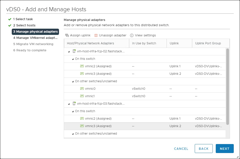
Step 6. Click NEXT.
Step 7. Do not migrate any VMkernel ports and click NEXT.
Step 8. Do not migrate any VM ports and click NEXT.
Step 9. Click FINISH to complete adding the ESXi host(s) to the vDS.
Procedure 4. Add the vMotion VMkernel Port(s) to the ESXi Host to the ESXi Host VM-Host-Infra-FCP-02 and VM-Host-Infra-FCP-03
Step 1. In the vCenter HTML5 Interface, under Hosts and Clusters select the ESXi host.
Step 2. In the center pane, click the Configure tab.
Step 3. In the list under Networking, select VMkernel adapters.
Step 4. Select Add Networking to Add host networking.
Step 5. Make sure VMkernel Network Adapter is selected and click NEXT.
Step 6. Select BROWSE to the right of Select an existing network.
Step 7. Select vMotion on the vDS and click OK.
Step 8. Click NEXT.
Step 9. Make sure the Network label is vMotion with the vDS in parenthesis. From the drop-down list, select Custom for MTU and make sure the MTU is set to 9000. Select the vMotion TCP/IP stack and click NEXT.
Step 10. Select Use static IPv4 settings and input the host’s vMotion IPv4 address and Subnet mask.
Step 11. Click NEXT.
Step 12. Review the parameters and click FINISH to add the vMotion VMkernel port.
Step 13. If this is an iSCSI-booted host, execute the instructions in the Appendix for an iSCSI-booted host being added in vCenter.
Step 14. Exit Maintenance Mode on each ESXi host in Maintenance Mode.
Procedure 5. VMware ESXi 7.0 U3 TPM Attestation
If your Cisco UCS servers have Trusted Platform Module (TPM) 2.0 modules installed, the TPM can provide assurance that ESXi has booted with UEFI Secure Boot enabled and using only digitally signed code. In the Cisco UCS section of this document, UEFI secure boot was enabled in the boot policy. A server can boot with UEFI Secure Boot with or without a TPM 2.0 module. If it has a TPM, VMware vCenter can attest that the server booted with UEFI Secure Boot.
Step 1. If your Cisco UCS servers have TPM 2.0 modules installed, TPM Attestation can be verified in the vSphere HTML5 Client. To get to the HTML5 client from the Web Client, click Launch vSphere Client (HTML5) in the upper center portion of the Web Client window.
Step 2. From the Hosts and Clusters window in the vSphere Client, click the FlashStack-Management cluster. In the center pane, click Monitor > Security. The Attestation status will appear as shown below, where 2 of the 3 hosts have TPM 2.0 modules installed:
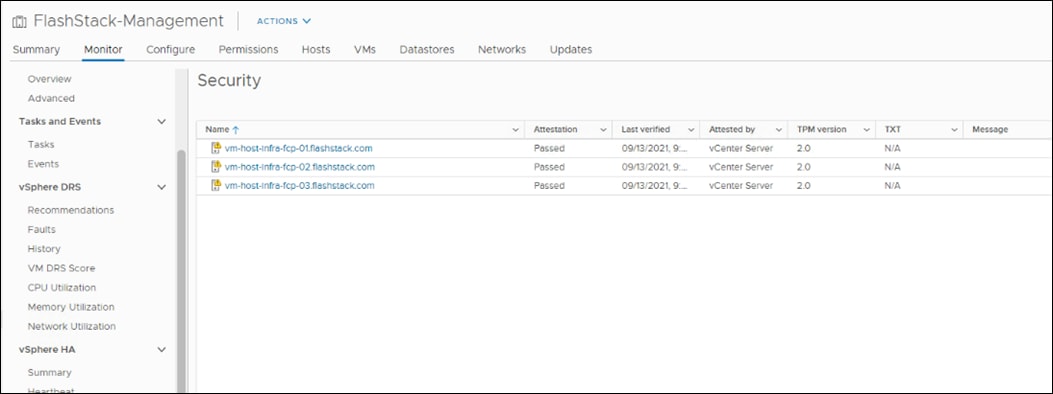
Note: It may be necessary to disconnect and reconnect a host from vCenter to get it to pass attestation the first time. Also, in this example, only the second host had a TPM module installed.
Boot failure when Server Profile is Moved
Typically hosts in FlashStack Datacenter are boot from SAN configured. Cisco UCS supports stateless compute where a server profile can be moved from one blade or compute node to another seamlessly.
When a server profile is moved from one blade to another blade server with the following conditions, ESXi host runs into PSOD and ESXi will fail to boot:
● TPM present in the node (Cisco UCS M5 and M6 family servers)
● Host installed with ESXi 7.0 U2 or above
● Boot mode is uEFI
● Error message: Unable to restore system configuration. A security violation was detected. https://via.vmw.com/security-violation
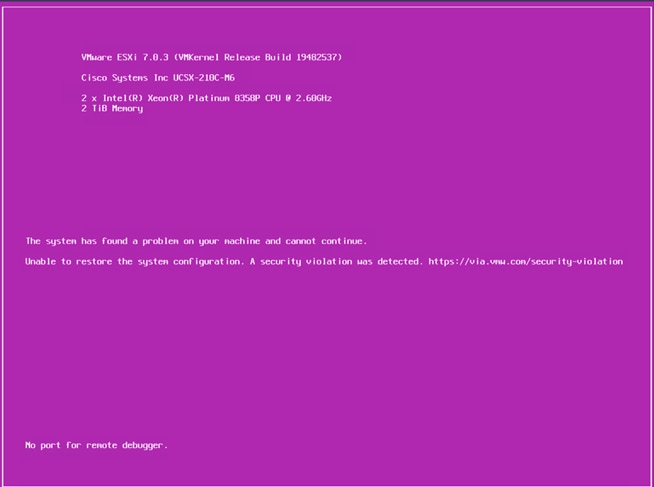
Resolution
When you install or upgrade to vSphere 7.0 Update 2 or later, and an ESXi host has a TPM, the TPM seals the sensitive information by using a TPM policy based on PCR values for UEFI Boot. This value is loaded during subsequent reboots if the policy is satisfied as true which is causing the issue.
Note: It is recommended to gather the recovery keys from all hosts once the ESXi setup is complete. When a server profile is moved from one blade to another, add the recovery key to the boot option.
Procedure 1. Gather the Recovery Keys
Step 1. Log into each host using SSH.
Step 2. Gather the recovery key using the following command:
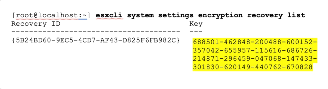
Step 3. Store the keys from all hosts in a safe location.
Step 4. After associating the Server Profile to the new compute-node or blade, stop the ESXi boot sequence by pressing Shift + O when you see the ESXi boot screen.
Step 5. Add the recovery key using following boot option: encryptionRecoveryKey=recovery_key
Step 6. Press Enter to continue the boot process.
Step 7. To make this change permanent across future reboots, ssh to the ESXi host and issue the following command:
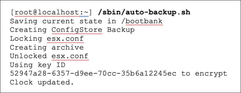
For more information, refer to: https://docs.vmware.com/en/VMware-vSphere/7.0/com.vmware.vsphere.security.doc/GUID-23FFB8BB-BD8B-46F1-BB59-D716418E889A.html#GUID-23FFB8BB-BD8B-46F1-BB59-D716418E889A
FlashStack Management Tools Setup
Cisco Data Center Network Manager (DCNM)–SAN
Cisco DCNM-SAN can be used to monitor, configure, and analyze Cisco fibre channel fabrics. Cisco DCNM-SAN is deployed as a virtual appliance from an OVA and is managed through a web browser. SAN Analytics can be added to provide insights into your fabric by allowing you to monitor, analyze, identify, and troubleshoot performance issues.
Note: Cisco DCNM-SAN is available as SAN Controller persona in Nexus Dashboard Fabric Controller (NDFC) and available exclusively on the Cisco Nexus Dashboard (ND) as an App. You can now enable the features you want at runtime (Fabric Controller (LAN), SAN Controller, and Fabric Discovery) which allows your clusters to scale better.
With the introduction of NDFC Release 12, users get a consistent experience across NDFC, and other services hosted on Nexus Dashboard including Insights and Orchestrator. As of publishing date of the document, Cisco DCNM 11.5(4) was used in the document as it was the suggested release. The future FlashStack design documents will use NDFC version 12 or higher.
Procedure 1. Configure Prerequisites
Step 1. Licensing. Cisco DCNM-SAN includes a 60-day server-based trial license that can be used to monitor and configure Cisco MDS Fibre Channel switches and monitor Cisco Nexus switches. Both DCNM server-based and switch-based licenses can be purchased. Additionally, SAN Insights and SAN Analytics requires an additional switch-based license on each switch. Cisco MDS 32Gbps Fibre Channel switches provide a 120-day grace period to trial SAN Analytics.
Note: If using the Cisco Nexus C93360YC-FX2 for SAN switching, it does not support SAN Analytics.
Step 2. Passwords. Cisco DCNM-SAN passwords should adhere to the following password requirements:
a. It must be at least eight characters long and contain at least one alphabet and one numeral.
b. It can contain a combination of alphabets, numerals, and special characters.
c. Do not use any of these special characters in the DCNM password for all platforms: <SPACE> " & $ % ' ^ = < > ; : ` \ | / , .*
Step 3. DCNM SNMPv3 user on switches. Each switch (both Cisco MDS and Nexus) needs an SNMPv3 user added for DCNM to use to query and configure the switch. On each switch, enter the following command in configure terminal mode (in the example, the userid is snmpuser):
snmp-server user snmpadmin network-admin auth sha <password> priv aes-128 <privacy-password>
Step 4. On Cisco MDS switches, type show run. If snmpadmin passphrase lifetime 0 is present, enter username snmpadmin passphrase lifetime 99999 warntime 14 gracetime 3.
Note: It is important to use auth type sha and privacy auth aes-128 for both the switch and UCS snmpadmin users.
Step 5. DCNM SNMPv3 user in UCSM. An SNMPv3 user needs to be added to UCSM to allow DCNM to query the LAN side of the fabric interconnects. In Cisco UCS Manager, click Admin. Navigate to All > Communication Management > Communication Services. Under SNMP, click Enabled, click Save Changes, and then click OK. Under SNMP Users, click Add. Enter the user name and enter and confirm the Password and Privacy Password.
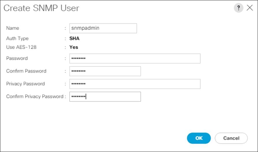
Step 6. Click OK and then click OK again to complete adding the user.
Procedure 2. Deploy the Cisco DCNM-SAN OVA
Step 1. Download the Cisco DCNM 11.5.1 Open Virtual Appliance for VMware from https://software.cisco.com/download/home/281722751/type/282088134/release/11.5(4)
Step 2. Extract dcnm-va.11.5.4.ova from the ZIP file.
Step 3. In the VMware vCenter HTML5 interface, click Menu > Hosts and Clusters.
Step 4. Right-click the FlashStack-Management cluster and select Deploy OVF Template.
Step 5. Select Local file then click UPLOAD FILES. Navigate to select dcnm-va.11.5.4.ova and click Open. Click NEXT.

Step 6. Name the virtual machine and select the FlashStack-DC datacenter. Click NEXT.
Step 7. Select the FlashStack-Management cluster and click NEXT.
Step 8. Review the details and click NEXT.
Step 9. Scroll through and accept the license agreements. Click NEXT.
Step 10. Select the appropriate deployment configuration size and click NEXT.
Note: If using the SAN Insights and SAN Analytics feature, it is recommended to use the Huge size.
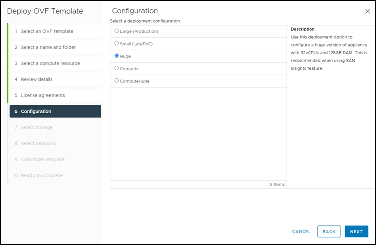
Step 11. Select Infra-DataStore1 and the Thin Provision virtual disk format. Click NEXT.
Step 12. Select IB-MGMT Network for all three Source Networks. Click NEXT.
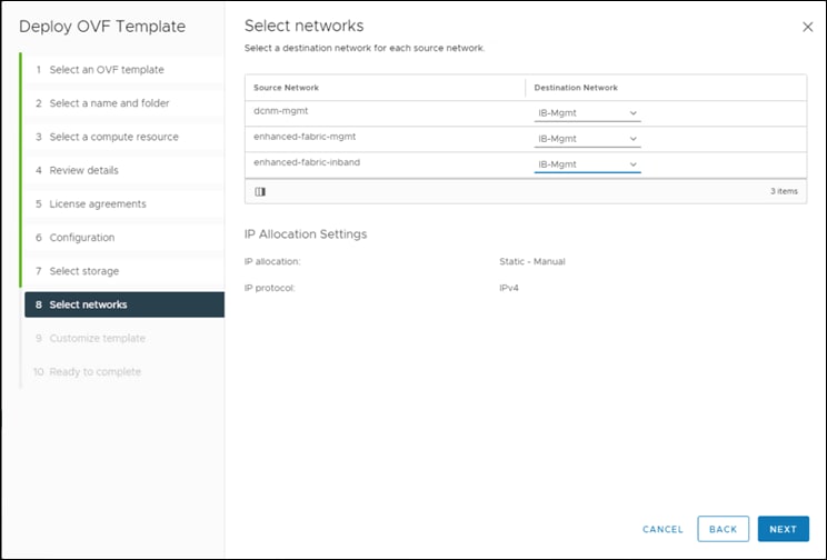
Step 13. Fill-in the management IP address, subnet mask, and gateway. Set the Extra Disk Size according to how many Cisco MDS switches you will be monitoring with this DCNM. If you are only monitoring the two Cisco MDS switches in this FlashStack deployment, set this field to 32. Click NEXT.
Step 14. Review the settings and click FINISH to deploy the OVA.
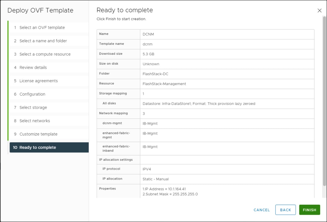
Step 15. After deployment is complete, right-click the newly deployed DCNM VM and click Edit Settings. Expand CPU and adjust the Cores per Socket setting until the number of Sockets is set to match the number of CPUs in the UCS servers used in this deployment.
The following example shows 2 sockets:
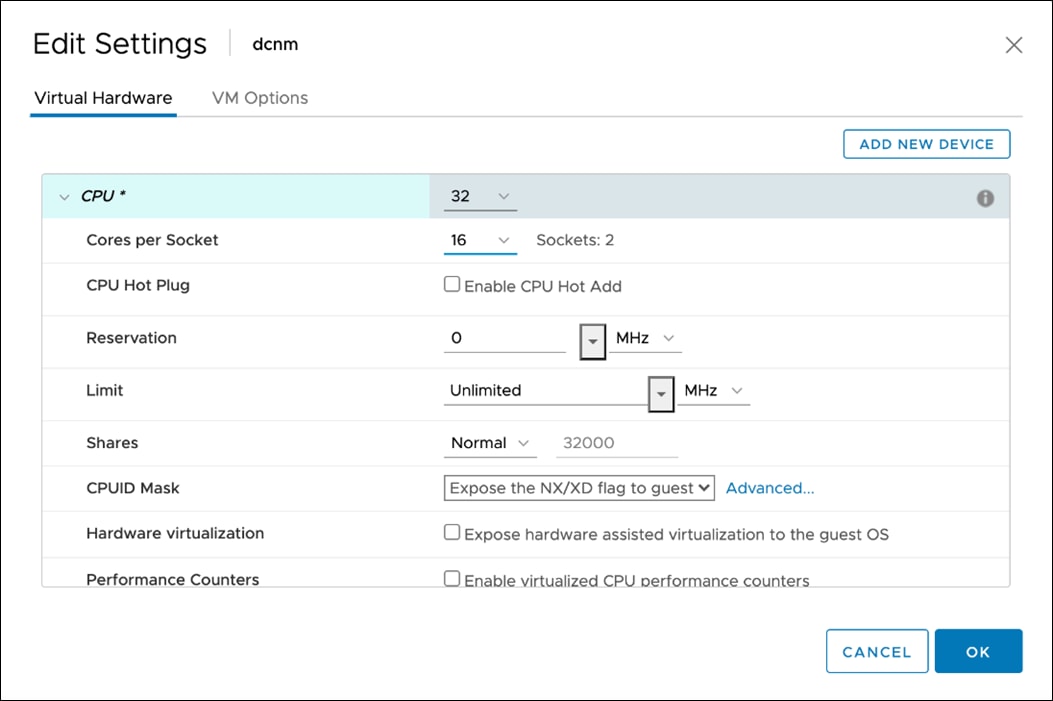
Step 16. Click OK to complete the change.
Step 17. Right-click the newly deployed DCNM VM and click Open Remote Console. Once the console is up, click ![]() to power on the VM. Once the VM has powered up, point a web browser to the URL displayed on the console.
to power on the VM. Once the VM has powered up, point a web browser to the URL displayed on the console.
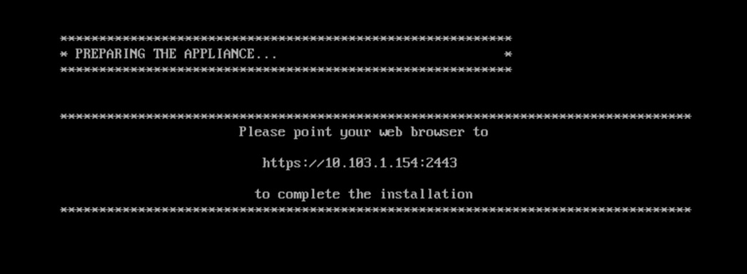
Step 18. Navigate the security prompts and click Get started.
Step 19. Make sure Fresh installation – Standalone is selected and click Continue.
Step 20. Select SAN only for the Installation mode and leave Cisco Systems, Inc. for the OEM vendor and click Next.
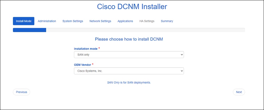
Step 21. Enter and repeat the administrator and database passwords and click Next.
Step 22. Enter the DCNM FQDN, a comma-separated list of DNS servers, a comma-separated list of NTP servers, and select the appropriate time zone. Click Next.
Step 23. The Management Network settings should be filled in. For Out-of-Band Network, a different IP address in the same subnet as the management address should be used. Only input the IPV4 address with prefix. Do not put in the Gateway IPv4 Address. Scroll down and click Next.
Step 24. Leave Internal Application Services Network set at the default setting and click Next.
Step 25. Review the Summary details and click Start installation.
Step 26. When the Installation status is complete, click Continue.
Step 27. In the vCenter HTML5 client under Hosts and Clusters, select the DCNM VM and click the Summary Tab. If an alert is present that states “A newer version of VMware Tools is available for this virtual machine.,” click Upgrade VMware Tools. Select Automatic Upgrade and click UPGRADE. Wait for the VMware Tools upgrade to complete.
Procedure 3. Configure DCNM-SAN
Note: When the DCNM installation is complete, the browser should redirect to the DCNM management URL.
Step 1. Log in as admin with the password previously entered.
Step 2. On the message that appears, select Do not show this message again and click No.
Note: If you have purchased DCNM server-based or switch-based licenses, follow the instructions that came with the licenses to install them. A new DCNM installation also has a 60-day trial license.
Step 3. In the menu on the left, click Inventory > Discovery > LAN Switches.
Step 4. Click ![]() to add LAN switches. In the Add LAN Devices window, enter the mgmt0 IP address of Nexus switch A in the Seed Switch box. Enter the snmpadmin user name and password set up in the Prerequisites section above. Set Auth-Privacy to SHA_AES. Click Next.
to add LAN switches. In the Add LAN Devices window, enter the mgmt0 IP address of Nexus switch A in the Seed Switch box. Enter the snmpadmin user name and password set up in the Prerequisites section above. Set Auth-Privacy to SHA_AES. Click Next.
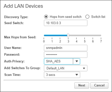
Step 5. LAN switch discovery will take a few minutes. In the LAN Discovery list that appears, the two Nexus switches and two Fabric Interconnects that are part of this FlashStack should appear with a status of “manageable.” Using the checkboxes on the left, select the two Nexus switches and two Fabric Interconnects that are part of this FlashStack. Click Add.
Step 6. After a few minutes click the Refresh icon in the upper right-hand corner, the two Nexus switches and two Fabric Interconnects that are part of this FlashStack will appear with detailed information. The SSH warning under SNMP Status can be ignored since only SNMP can be used to monitor Fabric Interconnects.
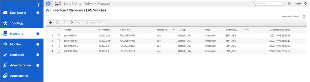
Step 7. In the menu on the left, click Inventory > Discovery > SAN Switches.
Step 8. Click  to add a switching fabric.
Step 9. Enter either the IP address or hostname of the first Cisco MDS 9132T switch. Leave Use SNMPv3/SSH selected. Set Auth-Privacy to SHA_AES. Enter the snmpadmin user name and password set up in the Prerequisites section above. Click Options>>. Enter the UCS admin user name and password. Click Add.
Note: If the Cisco Nexus C93360YC-FX2 switches are being used for SAN switching, substitute them here for MDS 9132Ts. They will need to be added again under SAN switches since LAN and SAN switching are handled separately in DCNM.
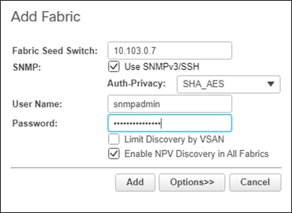
Step 10. Repeat steps 1-9 to add the second Cisco MDS 9132T and Fabric Interconnect.
The two SAN fabrics appear in the Inventory.
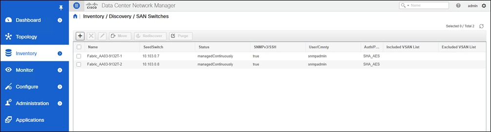
Step 11. Select Inventory > Discovery > Virtual Machine Manager.
Step 12. Click to add the vCenter.
Step 13. In the Add VCenter window, enter the IP address of the vCenter VCSA. Enter the administrator@vsphere.local user name and password. Click Add.
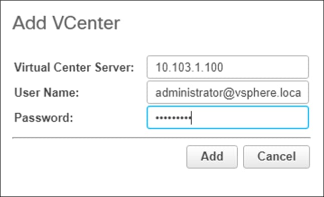
The vCenter appears in the inventory.
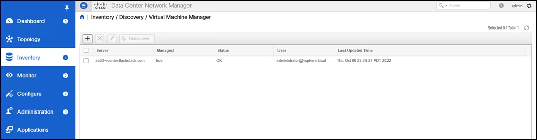
Step 14. Select Administration > Performance Setup > LAN Collections.
Step 15. Select the Default_LAN group and all information you would like to collect. Click Apply. Click Yes to restart the Performance Collector.
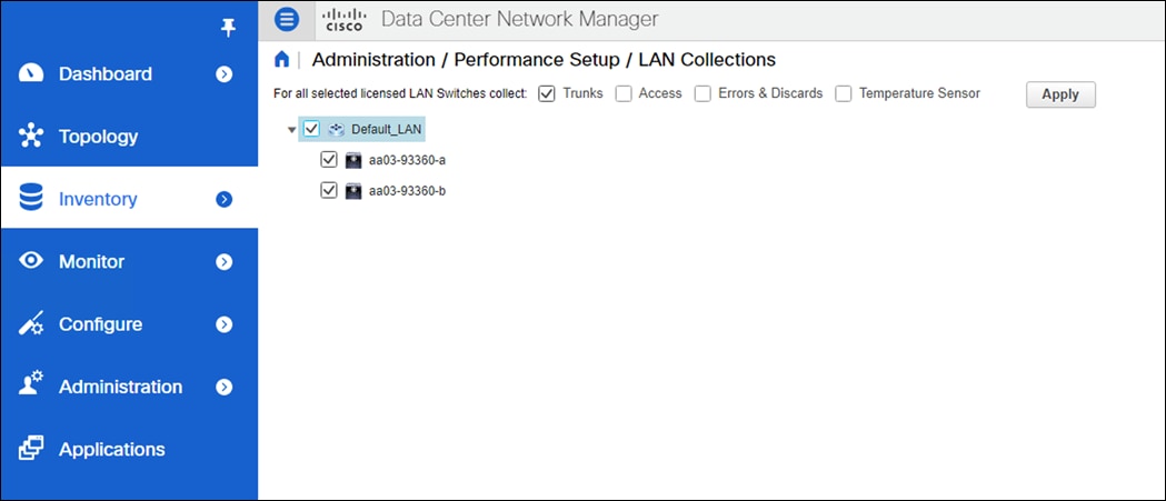
Step 16. Select Administration > Performance Setup > SAN Collections.
Step 17. Select both fabrics. Select all information you would like to collect and click Apply. Click Yes to restart the Performance Collector.
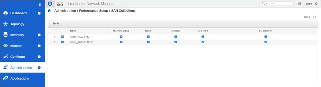
Step 18. Select Configure > SAN > Device Alias. Since device-alias mode enhanced was configured in the Cisco MDS 9132T switches, Device Aliases can be created and deleted from DCNM and pushed to the MDS switches.
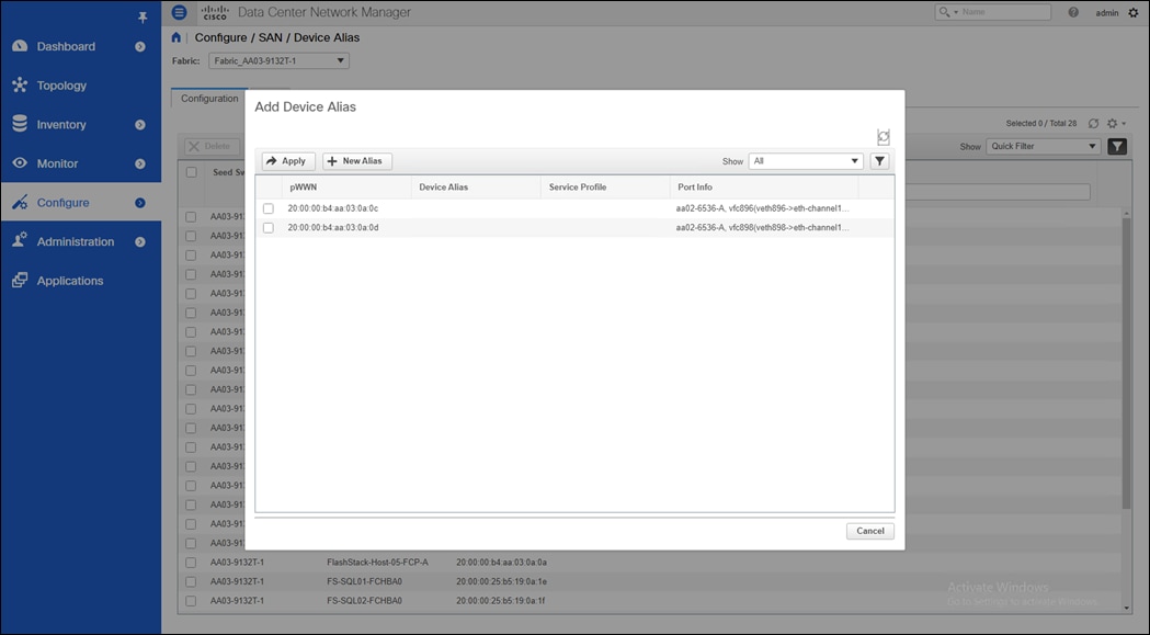
Step 19. Select Configure > SAN > Zoning. Just as Device Aliases can be created and deleted from DCNM, zones can be created, deleted, and modified in DCNM and pushed to the MDS switches. Remember to enable Smart Zoning and to Zone by Device Alias.
Now you can explore all the different options and information provided by DCNM SAN. See Cisco DCNM SAN Management for OVA and ISO Deployments Configuration Guide, Release 11.5(x).
Configure SAN Insights in DCNM SAN
The SAN Insights feature enables you to configure, monitor, and view the flow analytics in fabrics. Cisco DCNM enables you to visually see health-related indicators in the interface so that you can quickly identify issues in fabrics. Also, the health indicators enable you to understand the problems in fabrics. The SAN Insights feature also provides more comprehensive end-to-end flow-based data from the host to LUN.
● Ensure that the time configurations set above, including daylight savings settings, are consistent across the MDS switches and Cisco DCNM.
● SAN Insights requires the installation of a switch-based SAN Analytics license on each switch. To trial the feature, each switch includes a one-time 120-day grace period for SAN Analytics from the time the feature is first enabled.
● SAN Insights supports current Fibre Channel Protocol (SCSI) and NVMe over Fibre Channel (NVMe).
● SAN Insights works by enabling SAN Analytics and Telemetry Streaming on each switch. The switches then stream the SAN Analytics data to DCNM, which collects, correlates, and displays statistics. All configurations can be done from DCNM.
● Only Cisco MDS switches support SAN Analytics.
● For more information on SAN Insights, see the SAN Insights sections: Cisco DCNM SAN Management for OVA and ISO Deployments Configuration Guide, Release 11.5(x).
● For more information on SAN Analytics, see: https://www.cisco.com/c/en/us/td/docs/switches/datacenter/mds9000/sw/8_x/config/san_analytics/cisco-mds9000-san-analytics-telemetry-streaming-config-guide-8x.html.
Procedure 1. Configure SAN Insights in DCNM SAN
Step 1. Click Configure > SAN > SAN Insights. Click Continue.
Step 2. Select Fabric A. Click Continue.
Step 3. Select the Fabric A Cisco MDS switch. Under Install Query click None and from the drop-down list click Storage. Under Subscriptions, select SCSI & NVMe. Optionally, under Receiver, select the second IP address in the In-Band Management subnet configured for DCNM. Click Save, then click Continue.
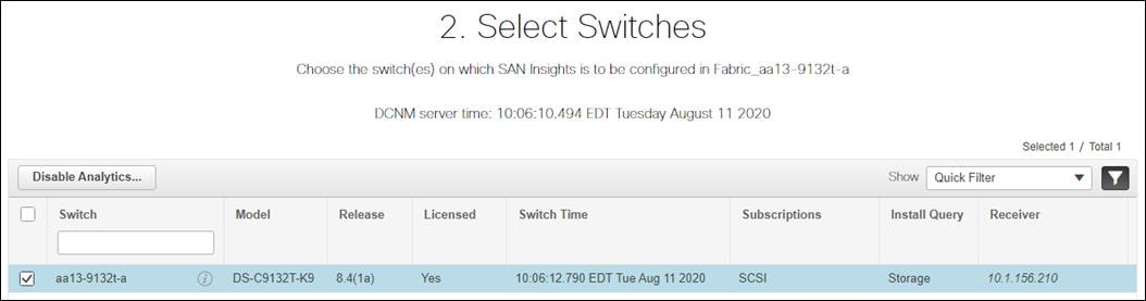
Step 4. Review the information and click Continue.
Step 5. Expand the switch and then the module. Under Enable / Disable SCSI Telemetry, click the left icon to enable telemetry on the ports connected to the FlashArray//X R3. Click Continue.
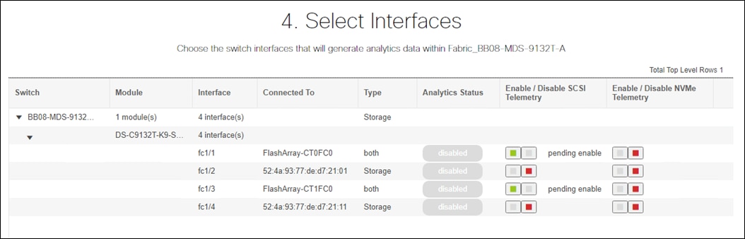
Step 6. Review the information and click Commit to push the configuration to the Cisco MDS switch.
Step 7. Ensure that the two operations were successful and click Close.
Step 8. Repeat steps 1-7 to install SAN Analytics and Telemetry on the Fabric B switch.
Note: After approximately two hours, you can view SAN Analytics data under the Dashboard and Monitor.
FlashStack Components
Cisco Intersight Assist
Cisco Intersight Assist helps you add endpoint devices to Cisco Intersight. FlashStack environment includes multiple devices that do not connect directly with Cisco Intersight. Any device that is supported by Cisco Intersight but does not connect directly with it, will need a connection mechanism. Cisco Intersight Assist provides that connection mechanism and helps you add devices into Cisco Intersight.
Cisco Intersight Assist is available within the Cisco Intersight Virtual Appliance, which is distributed as a deployable virtual machine contained within an Open Virtual Appliance (OVA) file format. You can install the appliance on an ESXi server. For more information, see the Cisco Intersight Virtual Appliance Getting Started Guide.
After claiming Intersight Assist into Intersight, you can claim endpoint devices using the Claim Through Intersight Assist option.
The following sections describe some of the sample FlashStack Orchestration and lifecycle management tasks that can be performed using Cisco Intersight.
Procedure 1. Configure Cisco Intersight Assist Virtual Appliance
Step 1. To install Intersight Assist from an Open Virtual Appliance (OVA) in your VMware FlashStack-Management Cluster, first download the latest release of the OVA from: https://software.cisco.com/download/home/286319499/type/286323047/release/1.0.9-342
Step 2. Refer to https://www.cisco.com/c/en/us/td/docs/unified_computing/Intersight/cisco-intersight-assist-getting-started-guide/m-installing-cisco-intersight-assist.html and set up the DNS entries for the Intersight Assist hostname as specified under Before you begin.
Step 3. From Hosts and Clusters in the VMware vCenter HTML5 client, right-click the FlashStack-Management cluster and click Deploy OVF Template.
Step 4. Specify a URL or browse to the intersight-virtual-appliance-1.0.9-342.ova file. Click NEXT.
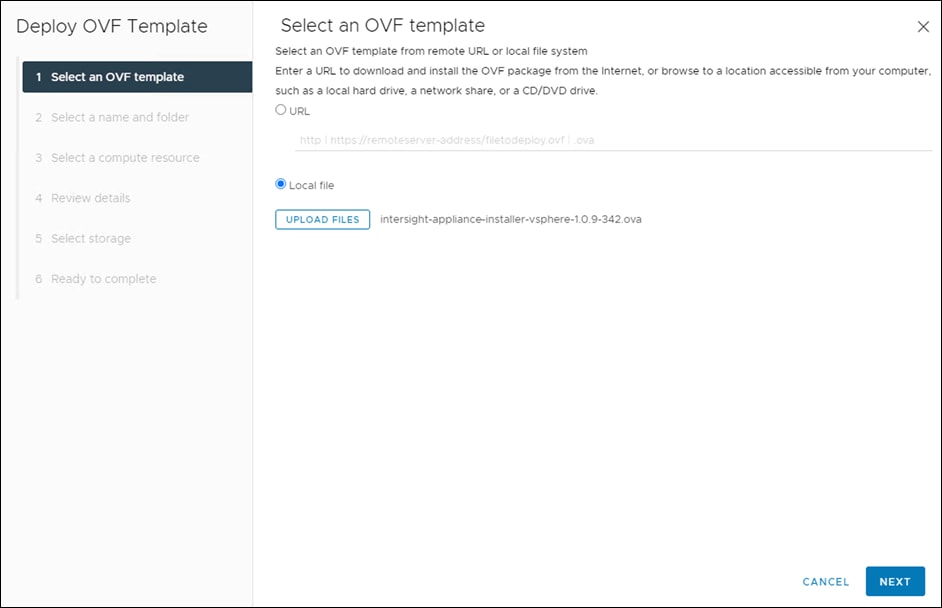
Step 5. Name the Intersight Assist VM and select the location. Click NEXT.
Step 6. Select the FlashStack-Management cluster and click NEXT.
Step 7. Review details and click NEXT.
Step 8. Select a deployment configuration and click NEXT.
Note: The Tiny (8 vCPU, 16 GiB RAM) deployment option is applicable only for Intersight Assist deployment without Workload Optimizer. Small deployment is the minimum requirement for Workload Optimizer.
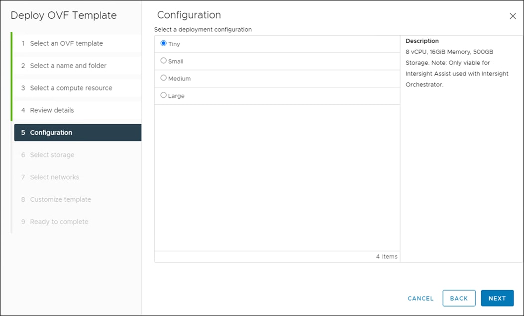
Step 9. Select Infra-DataStore1 for storage and select the Thin Provision virtual disk format. Click NEXT.
Step 10. Select IB-MGMT Network for the VM Network. Click NEXT.
Step 11. Fill in all values to customize the template. Click NEXT.
Step 12. Review the deployment information and click FINISH to deploy the appliance.
Step 13. Once the OVA deployment is complete, right-click the Intersight Assist VM and click Edit Settings.
Step 14. Expand CPU and adjust the Cores per Socket so that 2 Sockets are shown. Click OK.
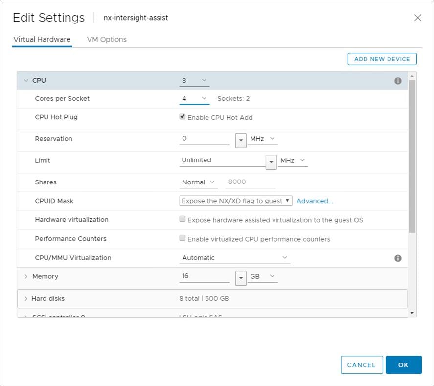
Step 15. Right-click the Intersight Assist VM and select Open Remote Console.
Step 16. Click ![]() to power on the VM.
to power on the VM.
Step 17. When you see the login prompt, close the Remote Console, and connect to https://intersight-assist-fqdn.
Note: It may take a few minutes for https://intersight-assist-fqdn to respond.
Step 18. Navigate the security prompts and select Intersight Assist. Click Proceed.
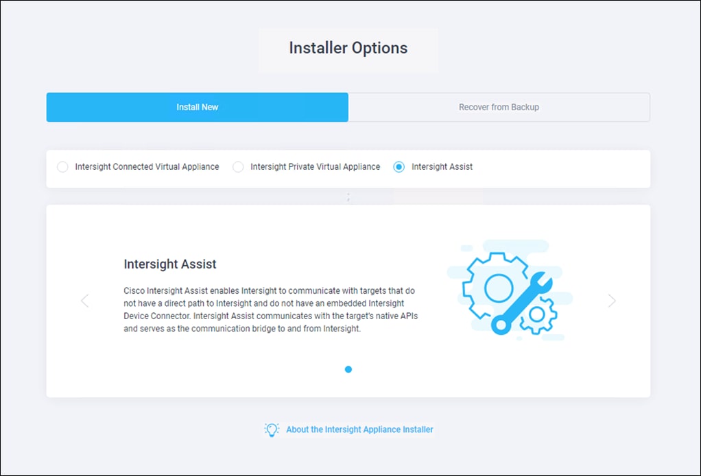
Step 19. Copy the Device ID and Claim Code shown in the Intersight Assist web interface to claim it in Cisco Intersight.
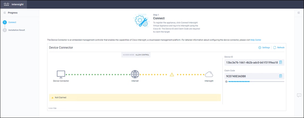
Step 20. Open a browser to Cisco Intersight: https://intersight.com.
Step 21. Log into your Intersight account.
Step 22. From Service Selector, select System
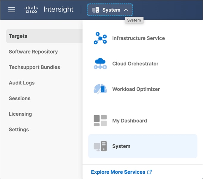
Step 23. From the left navigation pane, select Targets and click Claim a New Target
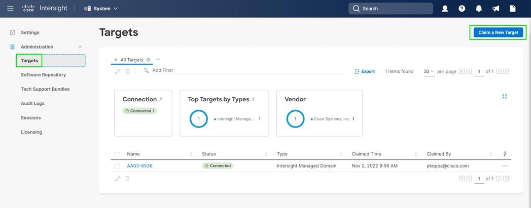
Step 24. Select Cisco Intersight Assist and click Start.
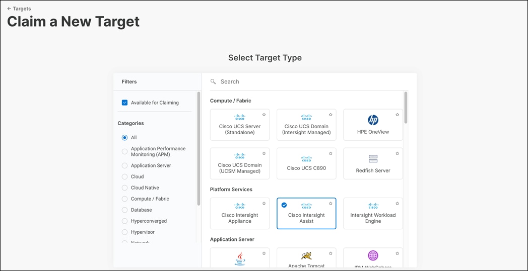
Step 25. Paste the copied Device ID and Claim Code from Intersight Assist web interface.
Step 26. Select the resource group (FlashStack-rg).
Step 27. Click Claim.
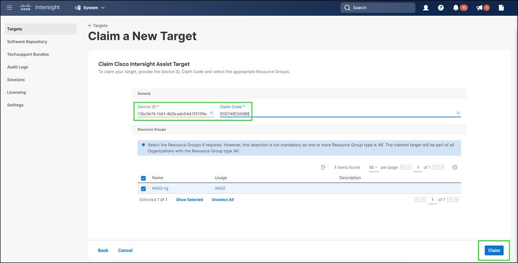
Step 28. In the Intersight Assist web interface, click Continue.
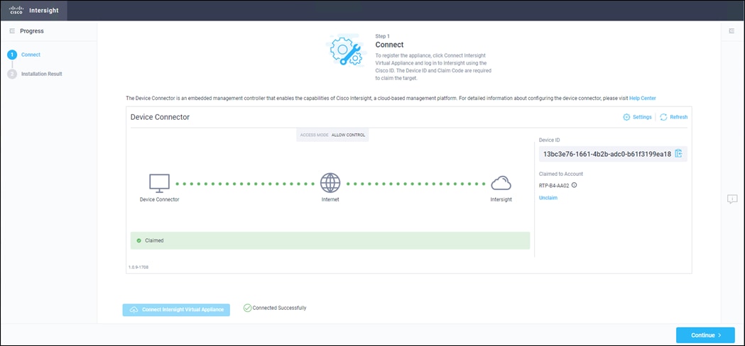
Note: The Cisco Intersight Assist software will now be downloaded and installed into the Intersight Assist VM. This can take up to an hour to complete.
Step 29. When the software download is complete, navigate the security prompts and an Intersight Assist login screen will appear. Log into Intersight Assist with the admin user and the password supplied in the OVA installation. Check the Intersight Assist status and log out of Intersight Assist.
VMware vCenter
Claiming a Pure VMWare vCenter requires the use of an Intersight Assist virtual machine. Deploy an Intersight assist appliance using the above-described procedure if one doesn’t exist.
Procedure 1. Claim a VMware vCenter in Cisco Intersight
Step 1. Open a browser to Cisco Intersight: https://intersight.com, and log into your Intersight account.
Step 2. From Service Selector, select System.
Step 3. From the left navigation pane, select Targets and click on Claim a New Target.
Step 4. Filter to Hypervisor and Select VMware vCenter.
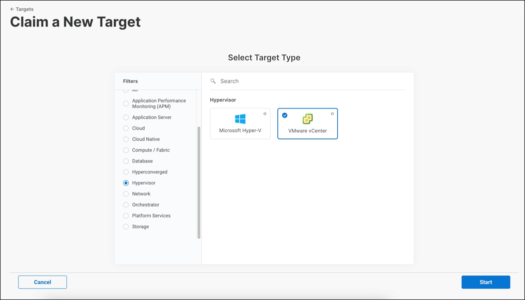
Step 5. Click Start.
Step 6. Fill in the vCenter information. If multiple Intersight Assist instances are deployed, make sure the Intersight Assist which has connectivity to the target is correctly selected.
Step 7. Make sure Secure option is enabled to indicate connection to the target should be established using HTTPS.
Step 8. Datastore Browsing controls whether Workload Optimizer scans vCenter datastores to identify files which are not used and can be deleted to reclaim space and improve actual disk utilization. For example, orphaned VMDK files.
Step 9. Enable retrieval of advanced memory metrics by Workload Optimizer Service. Only supported on vCenter Server version 6.5U3 or later. Guest VMs must run VMWare Tools 10.3.2 Build 10338 or later.
Step 10. Enabling Hardware Support Manager (HSM) allows vCenter to perform firmware operations on UCS servers claimed in the vCenter cluster. HSM is supported only from vCenter version 7.0 and above.
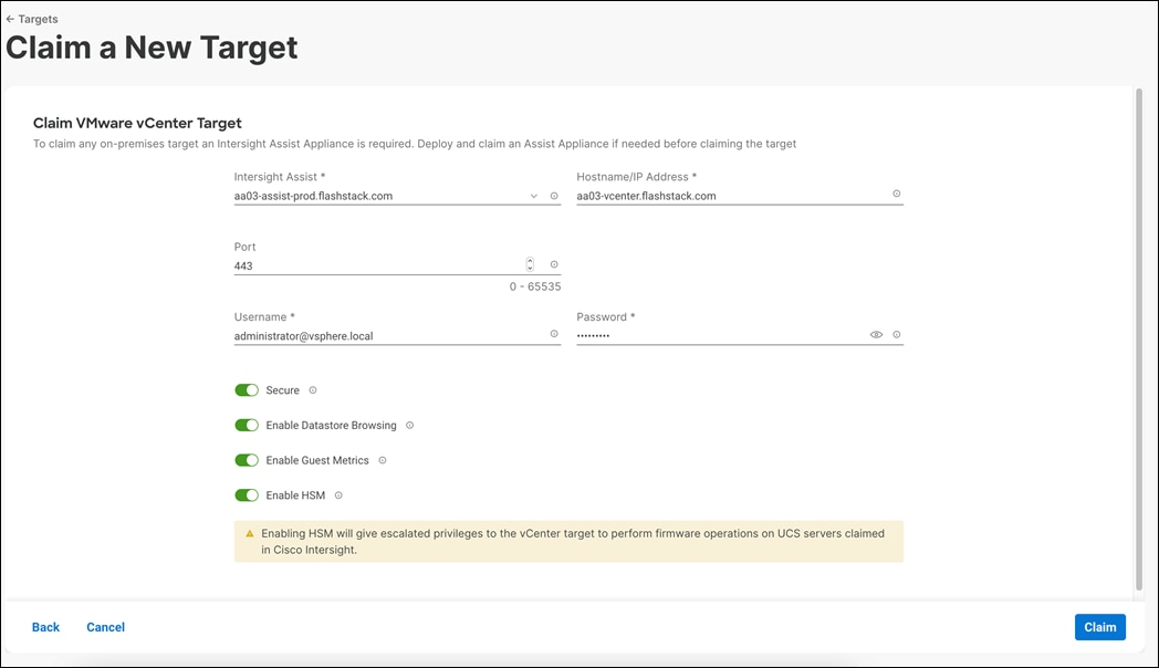
Step 11. Click on Claim.
Step 12. After a few minutes, the VMware vCenter will appear in the Devices list. It also can be viewed by clicking Intersight Assist in the Devices list.
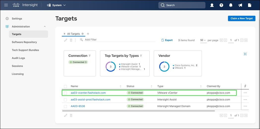
Step 13. Repeat steps 1 - 12 for all VMware vCenter targets.
Step 14. Detailed information obtained from the vCenter can now be viewed by clicking Virtualization from the menu.
Step 15. From Service Selector, select Infrastructure Service.
Step 16. From the left navigation pane, select Operate and click on Virtualization.
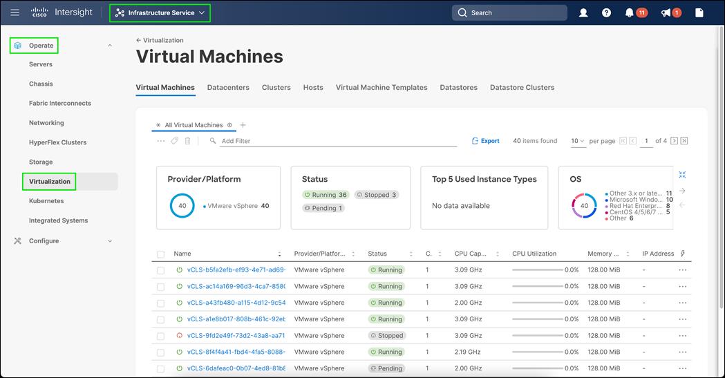
Claim FlashArray//XL and FlashArray//X in Cisco Intersight
Procedure 2. Claim a FlashArray in Cisco Intersight
Step 1. Open a browser to Cisco Intersight: https://intersight.com, and log into your Intersight account.
Step 2. From Service Selector, select System.
Step 3. From the left navigation pane, select Targets and click on Claim a New Target.
Step 4. In search bar, type Pure and Select Pure Storage FlashArray.
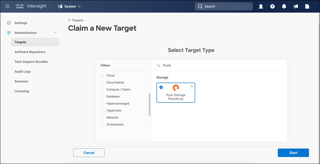
Step 5. Click on Start.
Step 6. Fill in the FlashArray information. If multiple Intersight Assist instances are deployed, make sure the Intersight Assist which has connectivity to the FlashArray management is correctly selected.
Step 7. Make sure Secure option is enabled to indicate connection to the target should be established using HTTPS.
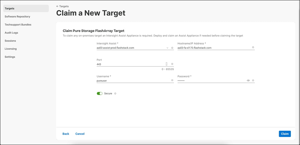
Step 8. After a few minutes, the FlashArray target will appear in the Devices list. It also can be viewed by clicking Intersight Assist in the Devices list.
Step 9.
Step 10. Repeat steps 1 – 9 for all FlashArray storages present.
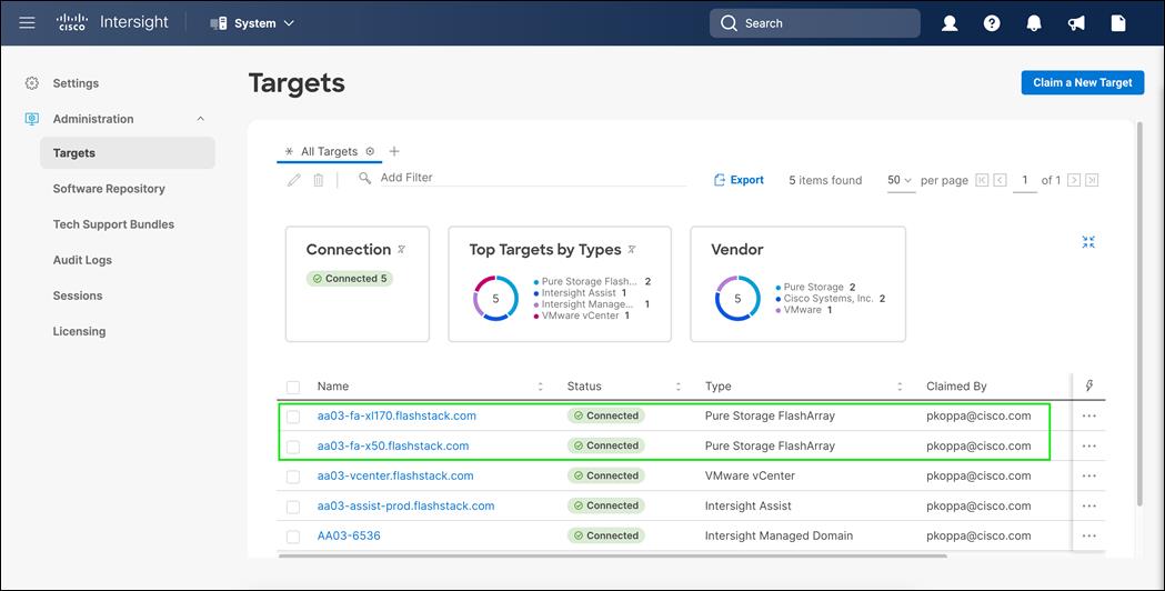
Claim Nexus and MDS Switches in Cisco Intersight
Claiming a Cisco Nexus 9000 and Cisco MDS switches also requires the use of an Intersight Assist virtual machine.
Procedure 1. Claim a Switch in Cisco Intersight
Step 1. Open a browser to Cisco Intersight: https://intersight.com
Step 2. Log into your Intersight account.
Step 3. From Service Selector, select System.
Step 4. From the left navigation pane, Select Network.
Step 5. Click Cisco Nexus Switch.
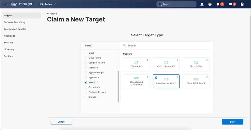
Step 6. Click Start.
Step 7. Fill in the Nexus switch information. If multiple Intersight Assist instances are deployed, make sure the Intersight Assist which has connectivity to the Nexus switch management is correctly selected.
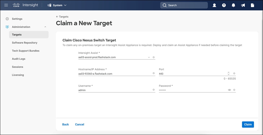
Step 8. After a few minutes, the Nexus 93360 switch will appear in the Devices list. It also can be viewed by clicking Intersight Assist in the Devices list.
Step 9. Repeat steps 1 – 8 on the other Nexus 93360 switch present.
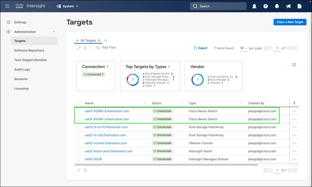
Step 10. Click Claim a New Target.
Step 11. In the Claim a New Target Wizard, click Cisco MDS Switch.
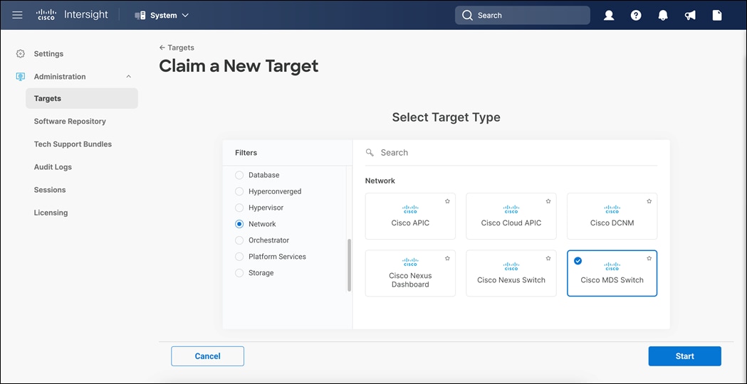
Step 12. Click on Start.
Step 13. Fill in the MDS switch information. If multiple Intersight Assist instances are deployed, make sure the Intersight Assist which has connectivity to the Nexus switch management is correctly selected.
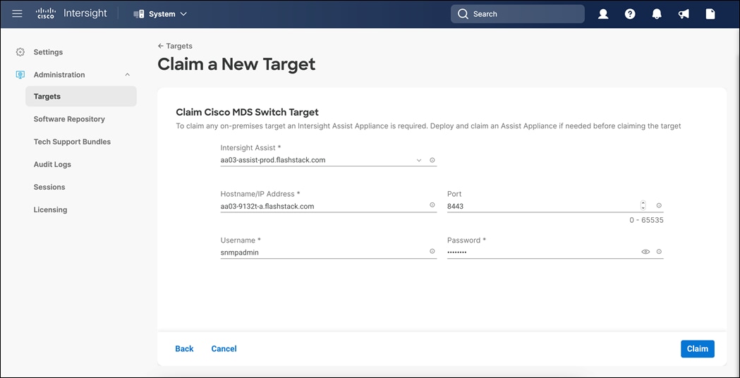
Step 14. After a few minutes, the MDS switch will appear in the Devices list. It also can be viewed by clicking Intersight Assist in the Devices list.
Step 15. Repeat for the other MDS switch.
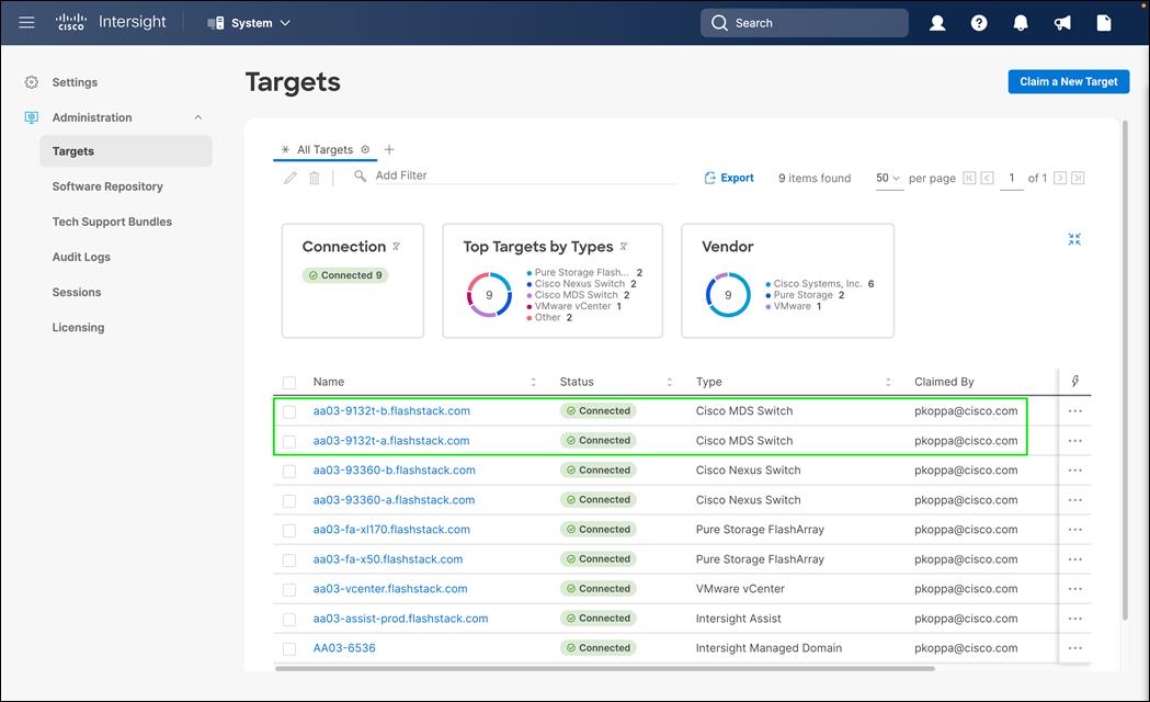
Cisco Intersight Cloud Orchestration
FC Host Registration using Cisco Intersight
Procedure 1. Register the FC Host Using Cisco Intersight
Step 1. Open a browser to Cisco Intersight: https://intersight.com, and log into your Intersight account.
Step 2. From Service Selector, select Cloud Orchestrator.
Step 3. From the left navigation pane, Select Workflows > All Workflows.
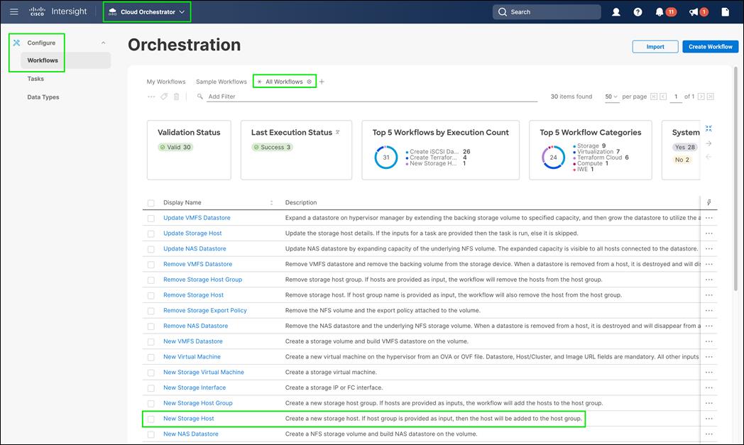
Step 4. Click on New Storage Host and click Execute.
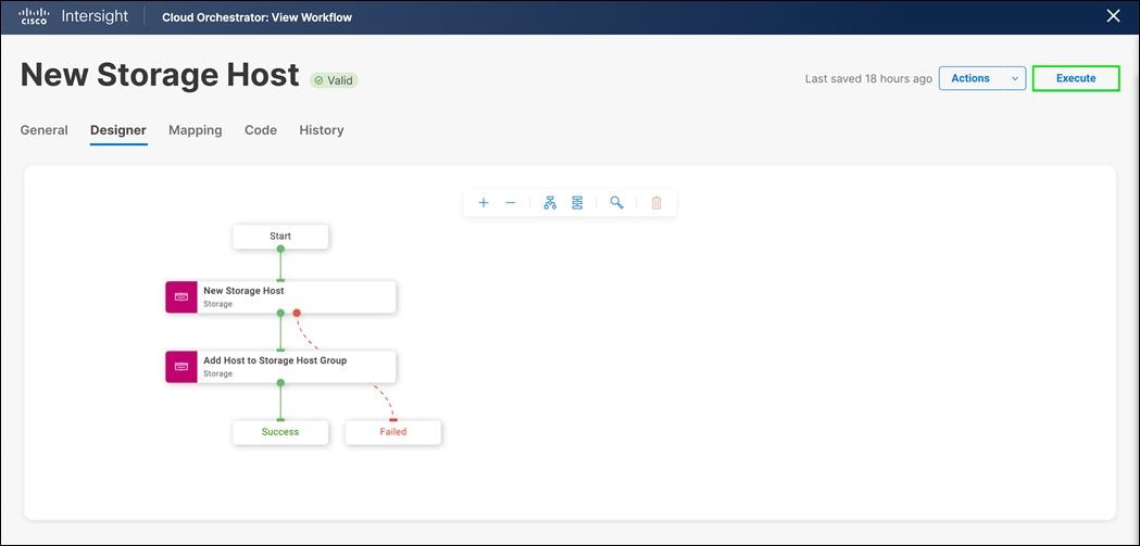
Step 5. Select the appropriate Organization (default by default).
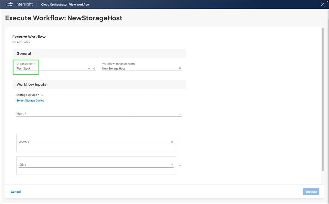
Step 6. Click on Select Storage Device and select the appropriate Pure Storage device.
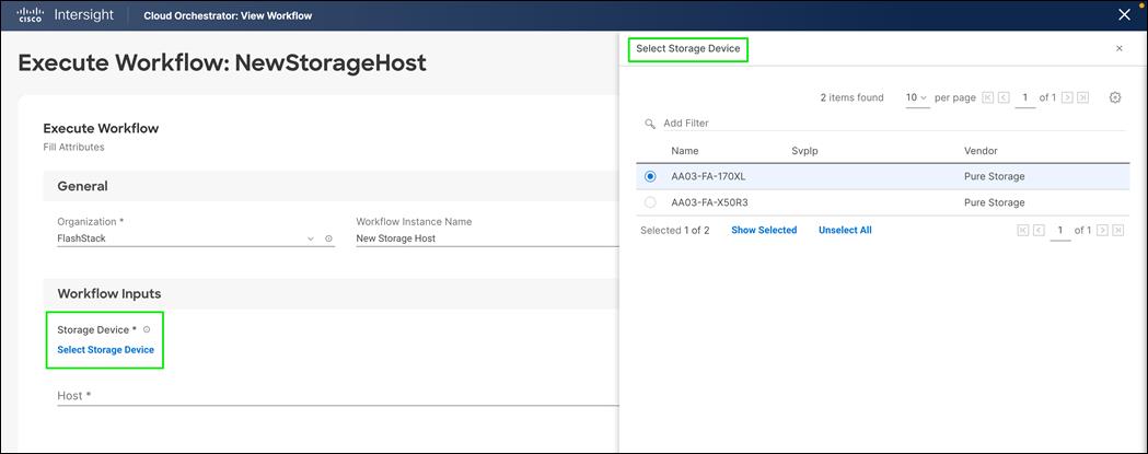
Step 7. Enter the name of the Host name and WWNs for host VM-Host-Infra-FCP-01.
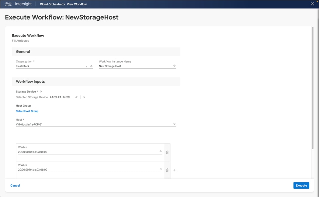
Step 8. Click on Select Host Group and select the Host group (Optional).
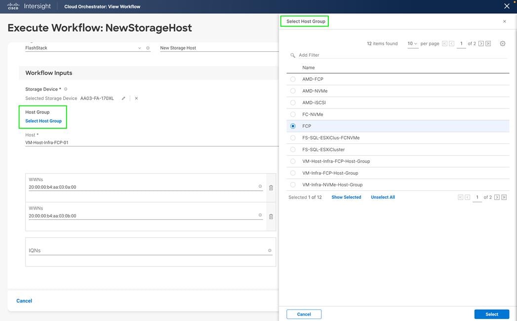
Step 9. Click Execute.
Step 10. Confirm that the execution is successful.
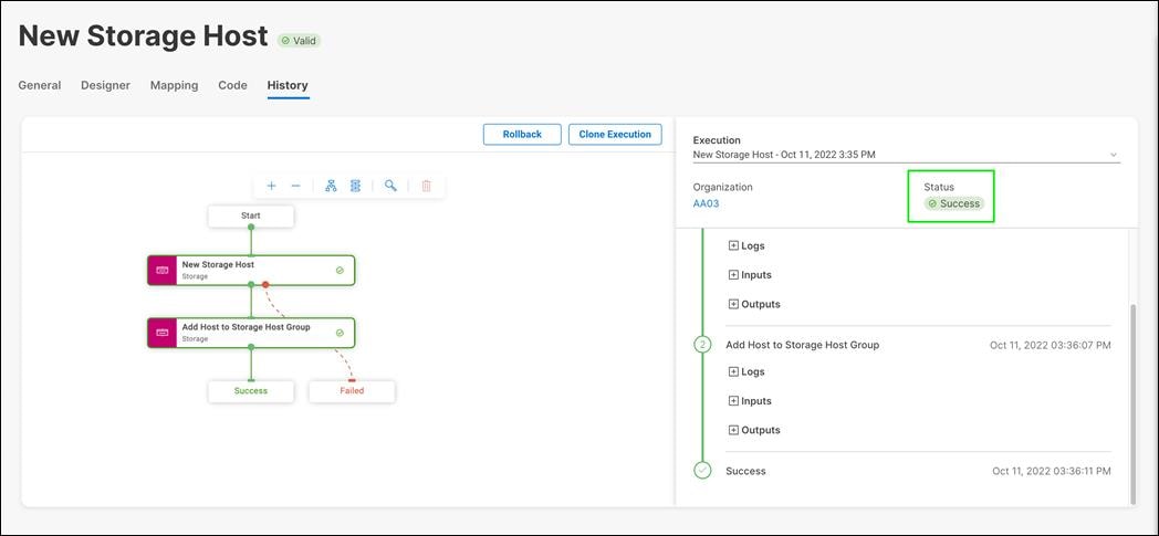
Step 11. Repeat steps 1 – 10 for all hosts.
Procedure 2. Create FC Host Group using Cisco Intersight
Step 1. Open a browser to Cisco Intersight, https://intersight.com, and log into your Intersight account.
Step 2. From Service Selector, select Cloud Orchestrator.
Step 3. From the left navigation pane, Select Workflows > All Workflows.
Step 4. Click on New Storage Host Group and click on Execute.
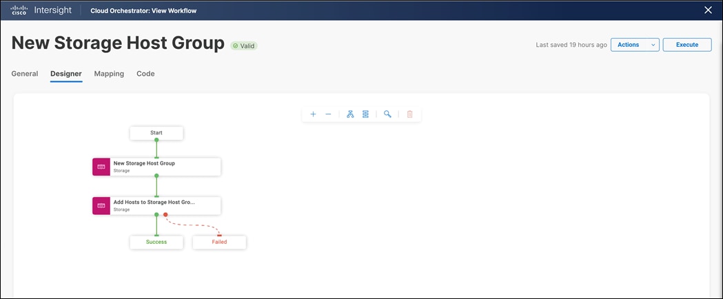
Step 5. Select the appropriate Organization (default by default).
Step 6. Click on Select Storage Device and select the appropriate Pure Storage device.
Step 7. Enter the name of the Host Group and enter all the host names for the new host group (Optional).
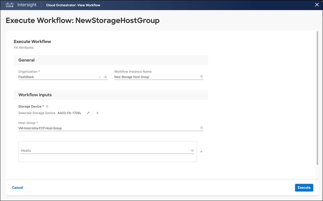
Step 8. Click on Execute
Step 9. Confirm that the execution is successful.
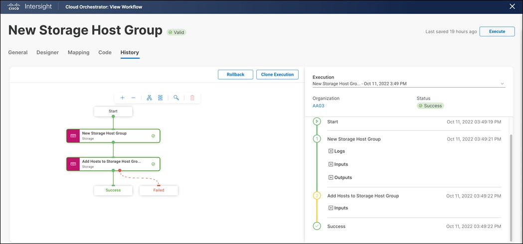
Procedure 3. Register the iSCSI Host using Cisco Intersight
Step 1. Open a browser to Cisco Intersight: https://intersight.com, and log into your Intersight account.
Step 2. From Service Selector, select Cloud Orchestrator
Step 3. From the left navigation pane, Select Workflows > All Workflows
Step 4. Click on New Storage Host and click on Execute
Step 5. Select the appropriate Organization (default by default).
Step 6. Select the appropriate Pure Storage device.
Step 7. Enter the name of the Host name and IQN for host VM-Host-Infra-iSCSI-01.
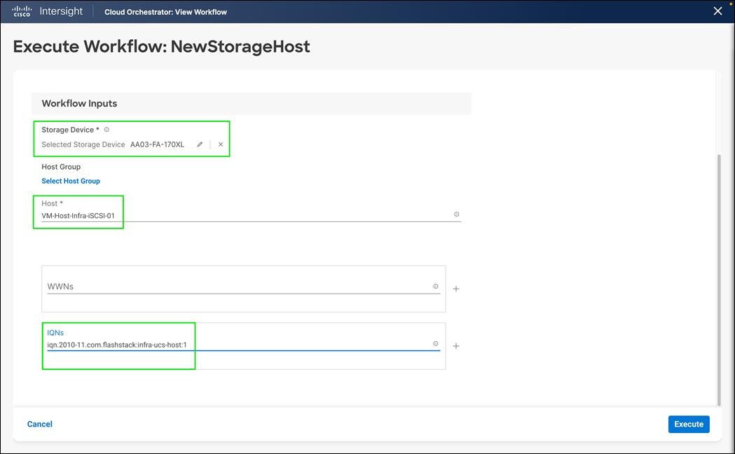
Step 8. Click on Select Host Group and select the Host group (Optional)
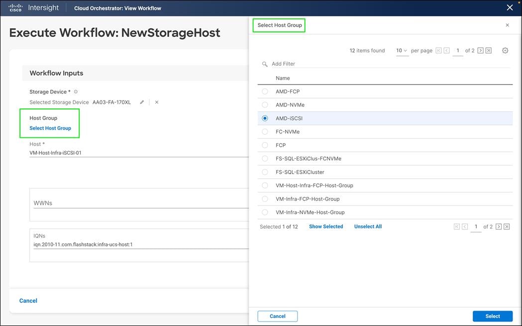
Step 9. Click Execute.
Step 10. Confirm that the execution is successful.
Step 11. Repeat steps 1 - 10 for all hosts.
Procedure 4. Create Host iSCSI Group using Cisco Intersight
Step 1. Open a browser to Cisco Intersight: https://intersight.com, and log into your Intersight account.
Step 2. From Service Selector, select Cloud Orchestrator.
Step 3. From the left navigation pane, Select Workflows > All Workflows.
Step 4. Click on New Storage Host Group and click on Execute.
Step 5. Select the appropriate Organization (default by default).
Step 6. Click on Select Storage Device and select the appropriate Pure Storage device.
Step 7. Enter the name of the Host Group and enter all the host names for the new host group (Optional).
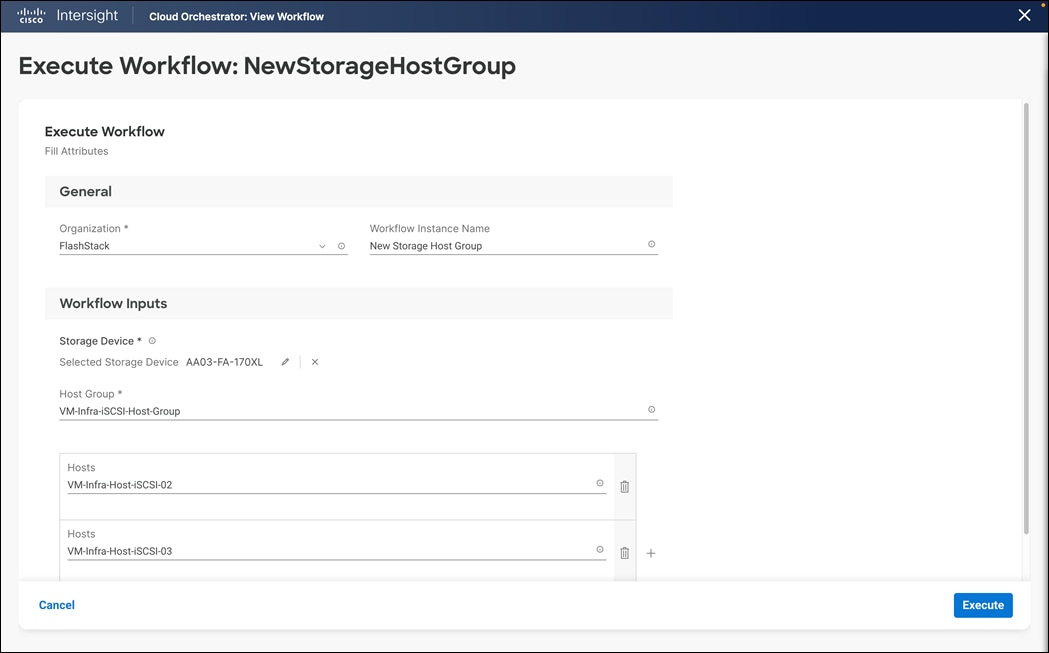
Step 8. Click on Execute
Step 9. Confirm that the execution is successful.

Procedure 5. Upgrade Cisco UCS Fabric Interconnects using Cisco Intersight from the Intersight SaaS Portal
Step 1. Open a browser to Cisco Intersight: https://intersight.com, and log into your Intersight account.
Step 2. From Service Selector, select Infrastructure Service.
Step 3. From the left navigation pane, Select Operate > Fabric Interconnects.
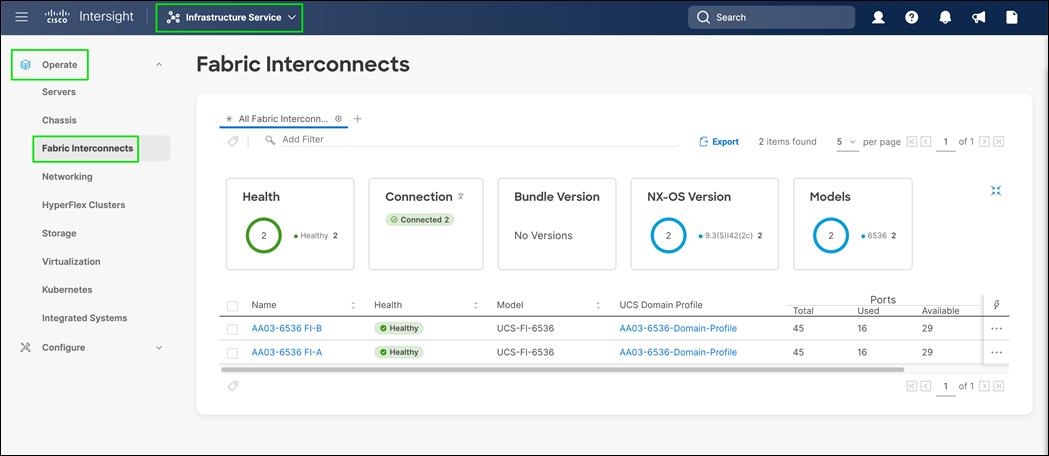
Step 4. From row action for the fabric interconnect and click on Upgrade Firmware.
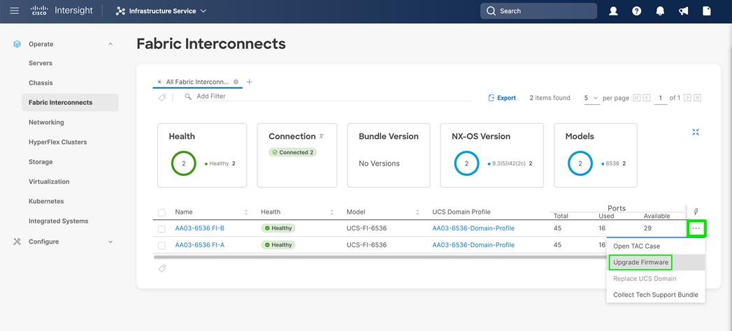
Step 5. On the Upgrade Firmware page, click Start.
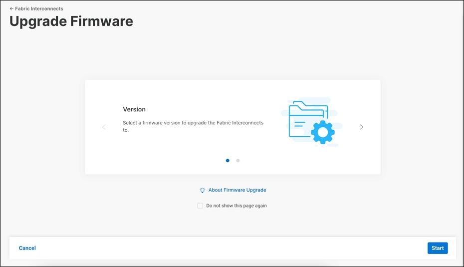
Step 6. On the General page, confirm selection of the switch Domain and click Next.
Step 7. On the Version page, select the fabric firmware bundle to which the Fabric Interconnects need to be upgraded, and click Next.
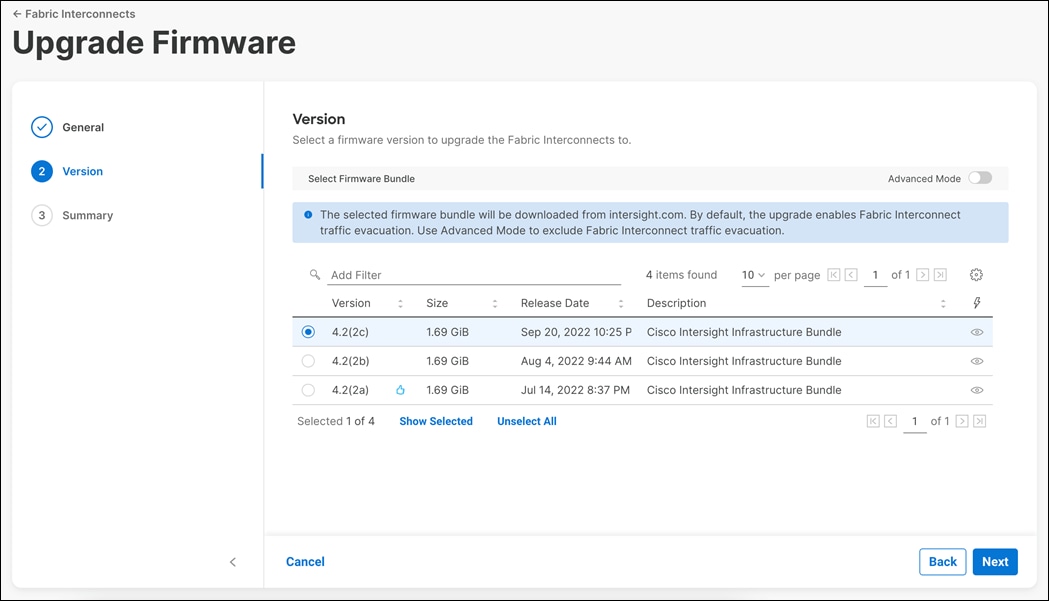
Step 8. On the Summary screen, verify the summary of the selected switches, the firmware version running on them, and the firmware version to which they will be upgraded, and click Upgrade.
Step 9. Confirm the upgrade request.
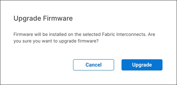
The firmware upgrade workflow begins.
Step 10. You can check the status of the upgrade workflow in the Execution Flow pane. Acknowledge any messages in the Execution Flow pane and click Continue to proceed with the upgrade.
Step 11. Click Continue.
Step 12. Verify if the upgrade is successful.
Procedure 6. Upgrade the Cisco UCS Servers using Cisco Intersight
Note: Only servers in associated state can be upgraded.
Note: Servers associated with server profiles bound to updating templates cannot be upgraded.
Note: Servers associated with global server profiles cannot be upgraded.
Step 1. Open a browser to Cisco Intersight: https://intersight.com, and log into your Intersight account.
Step 2. From Service Selector, select Infrastructure Service.
Step 3. From the left navigation pane, Select Operate > Servers.
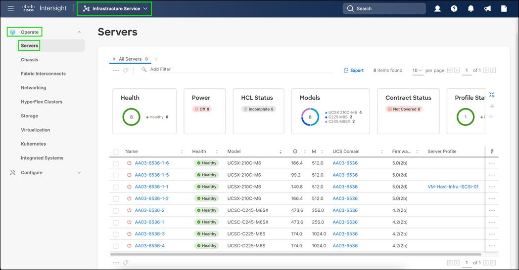
Step 4. Click on row action for the server to upgrade firmware and click on Upgrade Firmware.
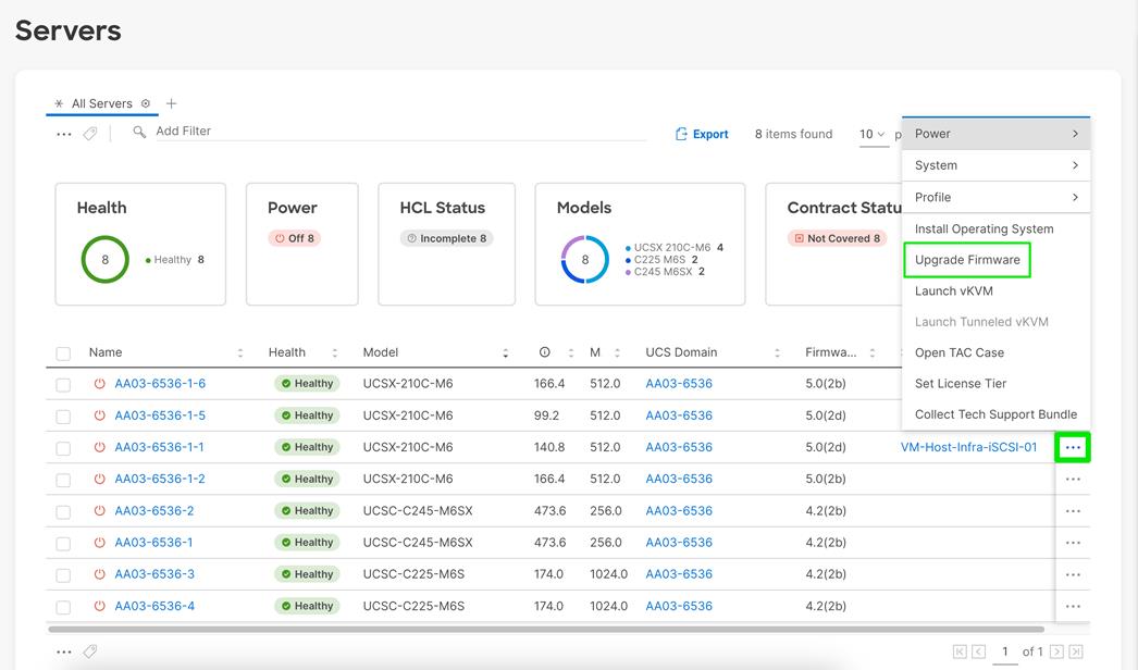
Step 5. On the Upgrade Firmware page, click Start.
Step 6. From the left navigation pane, click Servers, select a server, and perform an Upgrade Firmware action on it.
Step 7. On the Upgrade Firmware page, click Start.
Step 8. On the General page, confirm selection of the server and click Next.
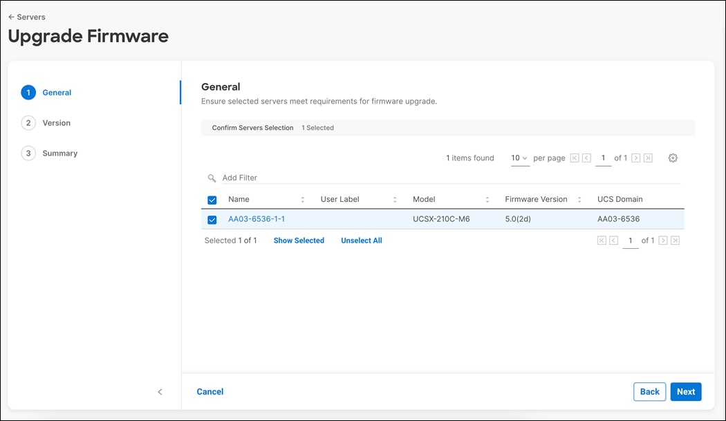
Step 9. On the Version page, select the fabric firmware bundle to which the Fabric Interconnects need to be upgraded, and click Next.
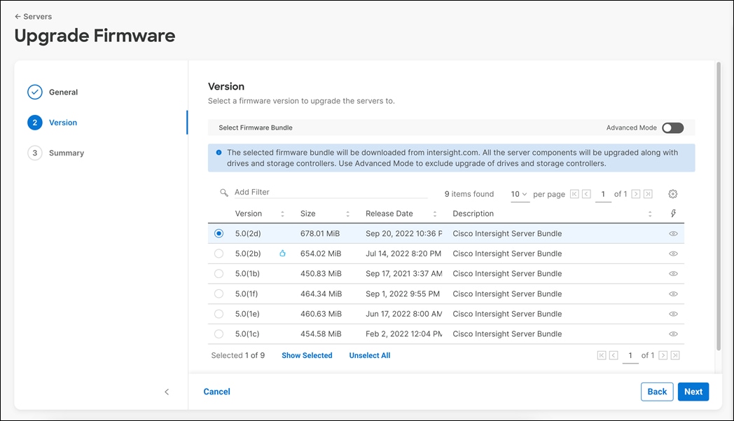
Step 10. On the Summary screen, verify the summary of the selected switches, the firmware version running on them, and the firmware version to which they will be upgraded, and click Upgrade.
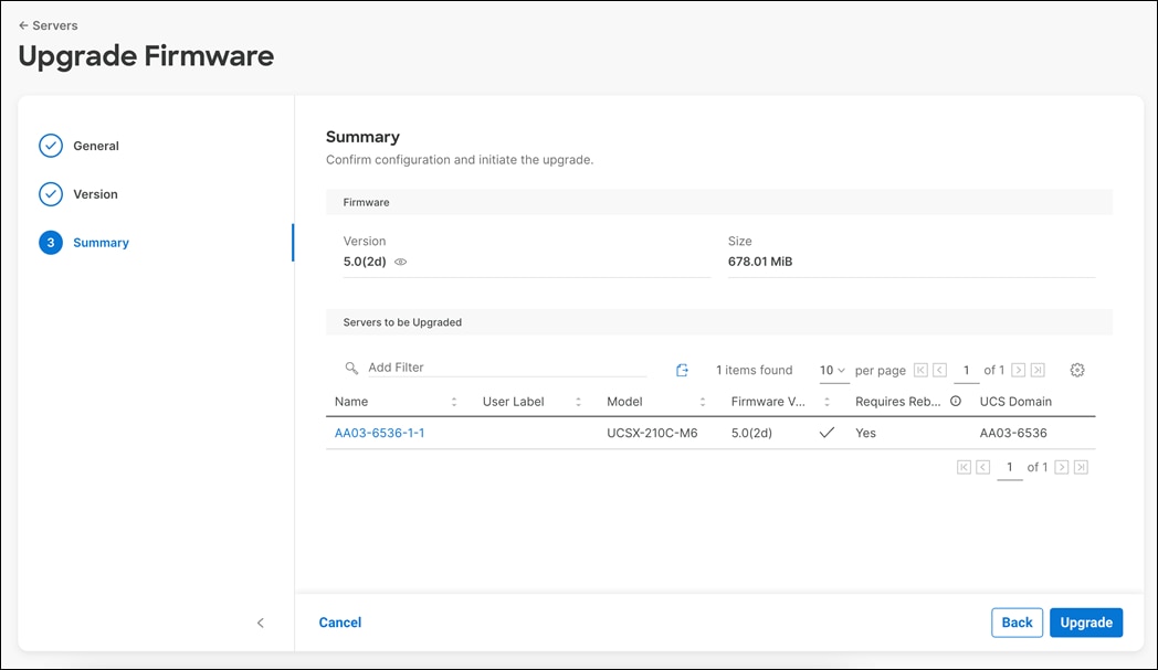
Step 11. Select Reboot Immediately to Begin Upgrade and Confirm the upgrade request and monitor the process for successful upgrade.
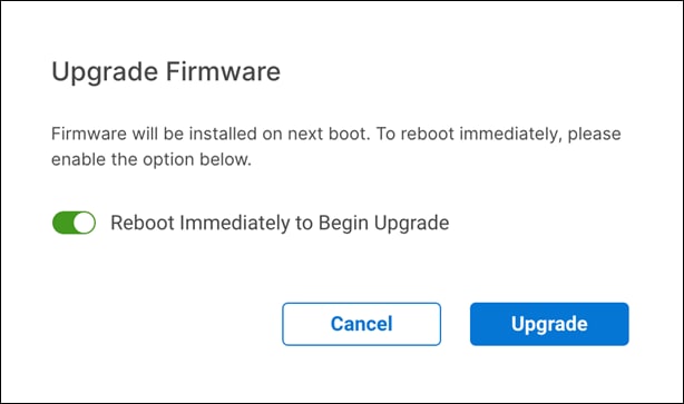
Pure Storage vSphere Client Plugin
The Pure Storage Plugin for the vSphere Client provides the ability to VMware users to have insight into and control of their Pure Storage FlashArray environment while directly logged into the vSphere Client. The Pure Storage plugin extends the vSphere Client interface to include environmental statistics and objects that underpin the VMware objects in use and to provision new resources as needed.
The Pure Storage vSphere Client Plugin will be accessible through the vSphere Client after registration through the Pure Storage Web Portal.
Procedure 1. Access the Pure Storage vSphere Client Plugin
Step 1. Go to Settings > Software.
Step 2. Click the edit icon in the vSphere Plugin panel.
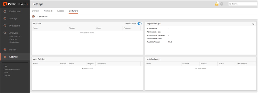
Step 3. Enter the vCenter information in the pop-up window and click Save.
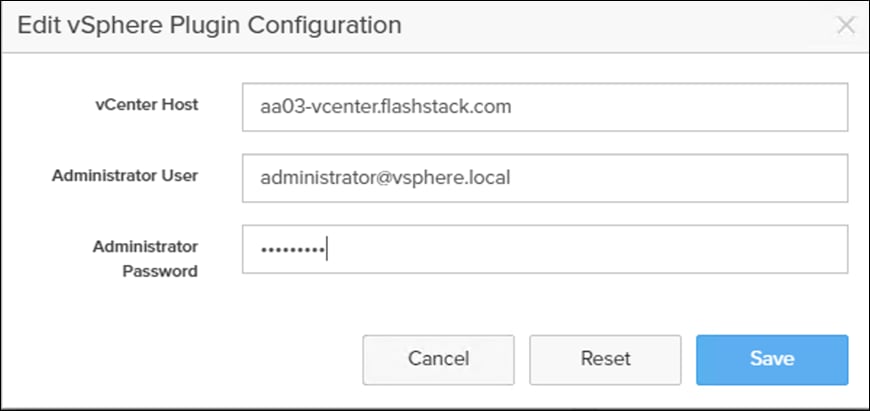
Step 4. After the discovery completes, click Install.
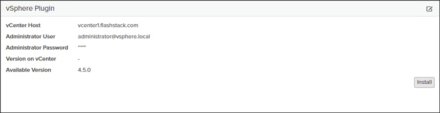
Step 5. In vCenter, select Pure Storage from the Menu.
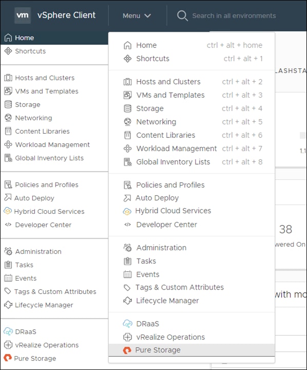
Step 6. Click Authenticate with Pure1.
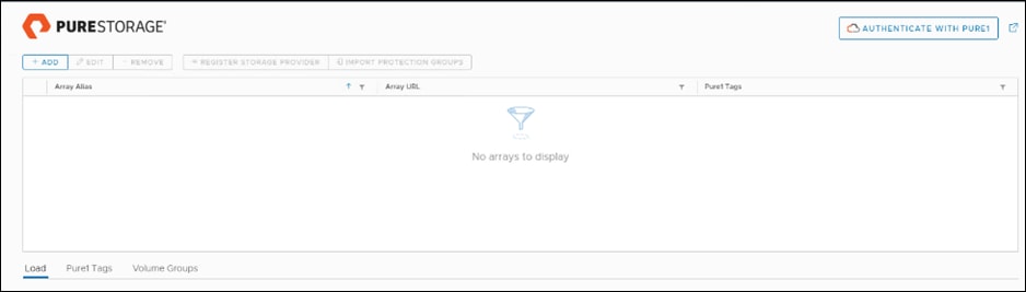
Step 7. Input your Pure1 JWT (link).
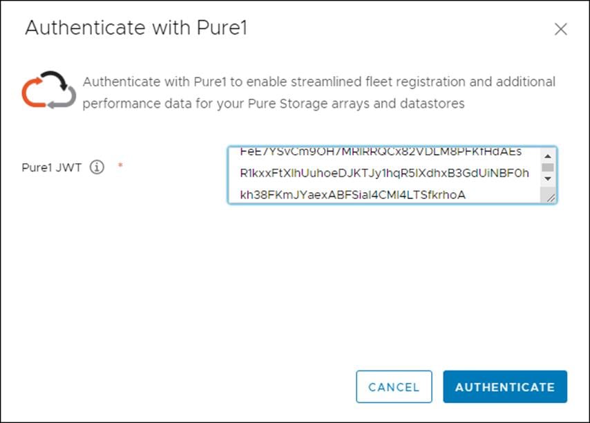
Step 8. Click Authenticate.
Step 9. Click Add.
Step 10. Click Import Arrays from Pure1 and input the Username and Password.
Step 11. Click Import Arrays from Pure1 and input the Username and Password.
Step 12. Click Done.
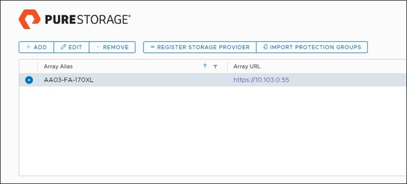
Step 13. Alternatively, provide array details in the Add a Single Array tab to add the Array manually.
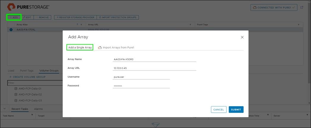
Step 14. Select the newly added array and click Register Storage Provider.
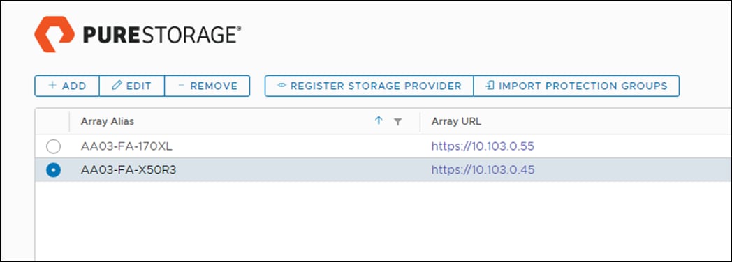
Step 15. Enter Username and Password.
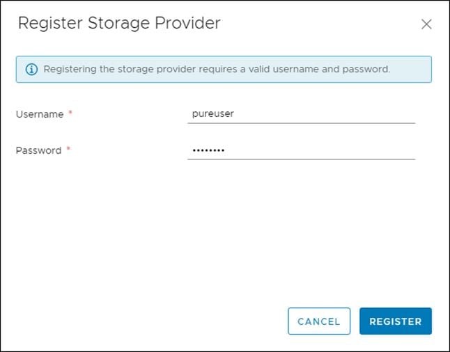
Step 16. Click Register.
Note: There is also an option to import from Pure1.
Step 17. Select Import Arrays from Pure1 in Add option.
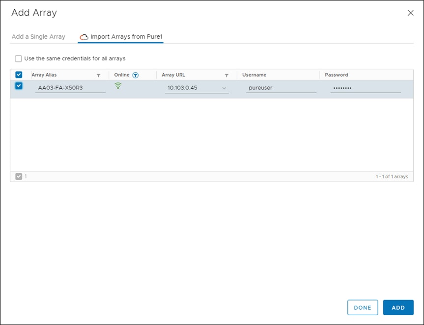
Step 18. Select the array and click Add.
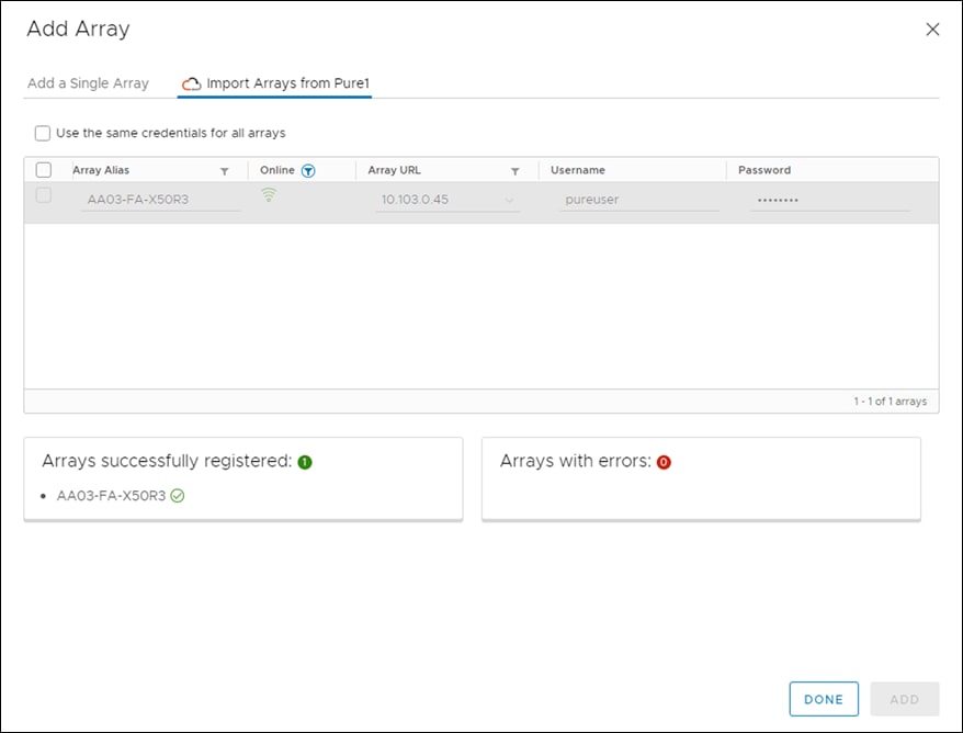
Procedure 2. Create VMFS Datastore using Pure vSphere Plugin
Step 1. In vCenter, click Host and Clusters.
Step 2. Right-click the FlashStack Cluster and select Pure Storage > Create Datastore.

Step 3. Click VMFS.
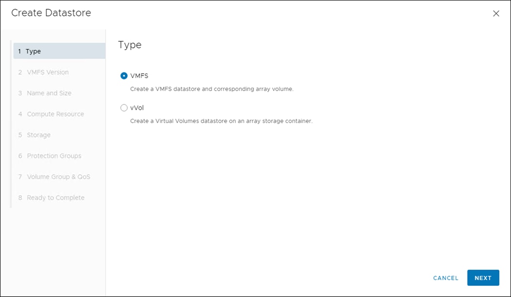
Step 4. Click Next.
Step 5. Keep VMFS 6 selected.
Step 6. Click Next.
Step 7. Enter a Datastore Name and Datastore Size.
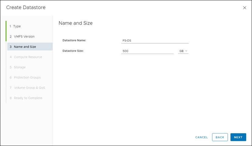
Step 8. Click Next.
Step 9. Select the Cluster under Compute Resources.
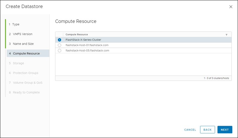
Step 10. Click Next.
Step 11. Select the Registered FlashArray.
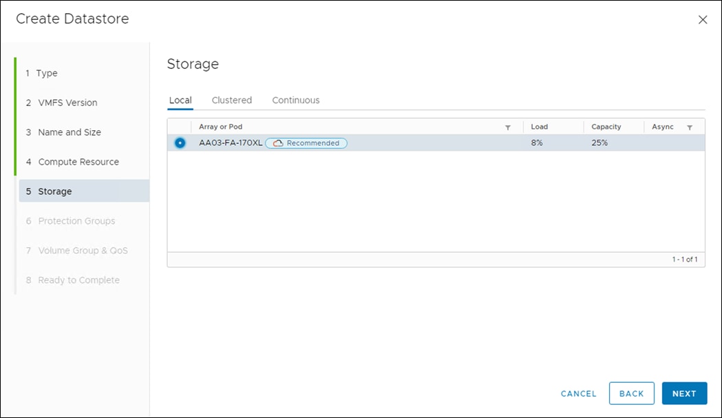
Step 12. Optionally, add to the protection group created earlier and click Next.
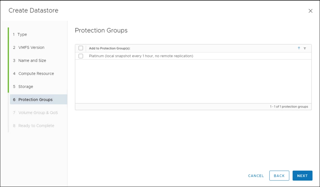
Step 13. Click Next on the Volume Group & QoS page.
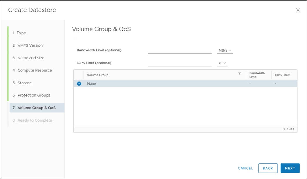
Step 14. Review the information and click Finish.
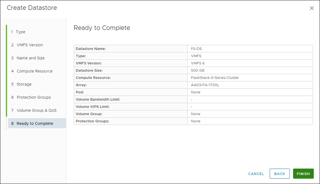
Procedure 3. Create vVol Datastore
Step 1. In vCenter, select Host and Clusters.
Step 2. Right-click the FlashStack Cluster and select Pure Storage > Create Datastore.
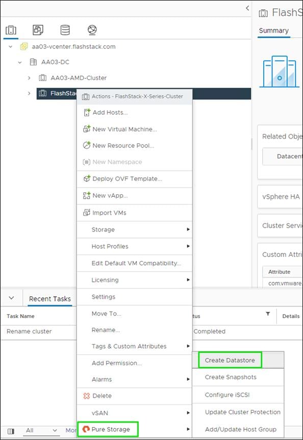
Step 3. Click vVol.
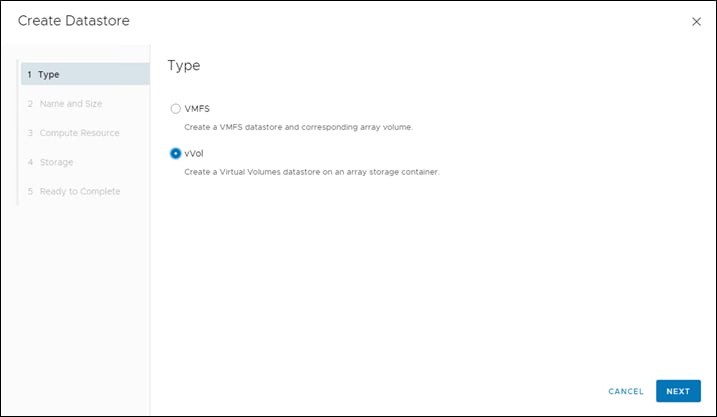
Step 4. Click Next.
Step 5. Enter a Datastore Name.
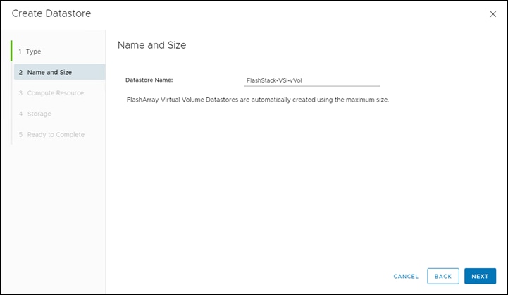
Step 6. Click Next.
Step 7. Click the Cluster under Compute Resources.
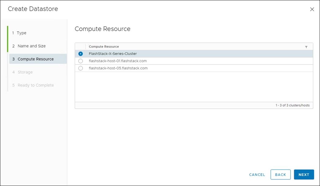
Step 8. Click Next.
Step 9. Click the Registered FlashArray.
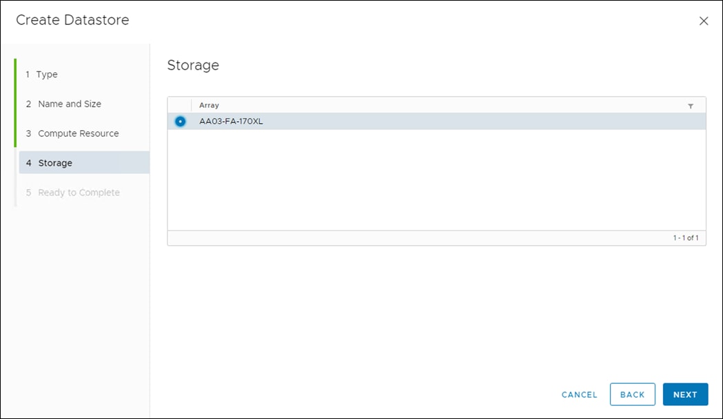
Step 10. Click Next.
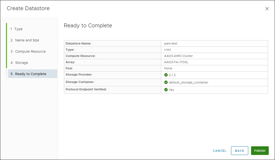
Step 11. Review the information and click Finish.
Procedure 4. Configure NVMe over FC on ESXi Host
Step 1. Log into vCenter and on the ESXi host verify the storage adapter information, there will be four adapters listed, two among them being the FC-NVMe initiators.
Step 2. Once you click on one, you will see more information appear in the Details panel:
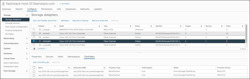
Note: If the zoning is complete at this point no additional steps are required.
Procedure 5. Create the Host and Host Group Objects on the FlashArray
In NVMe-oF, initiators and target (the FlashArray) use NVMe Qualified Name (NQN). With NVMe-oF/FC, NQNs do not replace FC WWNs–they both exist.
Note: The WWN of each side is what is advertised on the FC layer to enable physical connectivity and zoning. The NQN is what enables the NVMe layer to communicate to the correct endpoints on the FC fabric. You can look at it in a similar way as networking in IP (MAC addresses and IPs).
Step 1. For each ESXi host, you need to create a host object on the FlashArray, then add the NQN to it. To get NQN, SSG int ESXi host and run:
esxcli nvme info get
Step 2. Copy the NQN.
Step 3. Log into the FlashArray.
Procedure 6. Host Registration from the Pure Storage Web Portal
Step 1. Click Storage > Hosts.
Step 2. Click the + icon in the Hosts Panel.
Step 3. After clicking the Create Host (+) option, a pop-up will appear to create an individual host entry on the FlashArray.
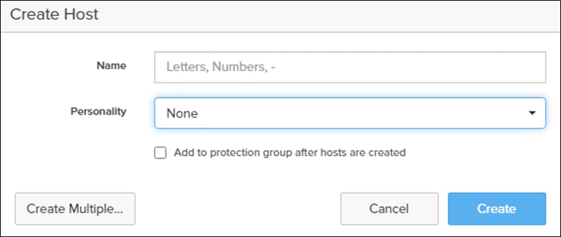
Step 4. To create more than one host entry, click the Create Multiple… option, filling in the Name, Start Number, Count, Personality as ESXi and Number of Digits, with a “#” appearing in the name where an iterating number will appear:
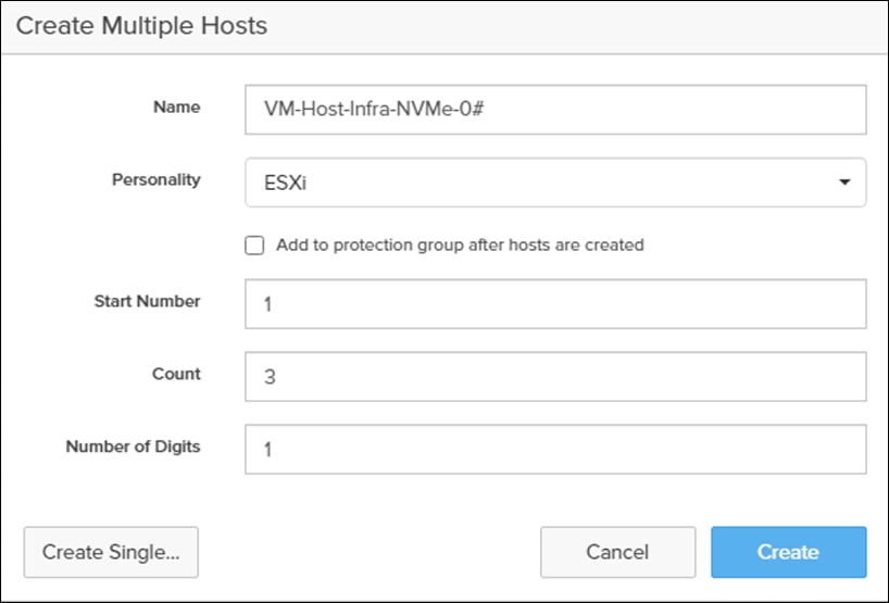
Step 5. Click Create to add the hosts.
Step 6. For each host created, select the host.
Step 7. In the Host view, select Configure NQNs… from the Host Ports menu.
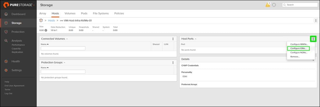
Step 8. A pop-up will appear for Configure NVMe-oF NQNs for <Host> Within this pop-up, enter the appropriate NQN of this specific host.
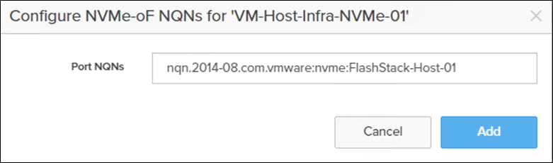
Step 9. Click Add.
Step 10. Repeat steps 1-9 for each host created.
Procedure 7. Create NVMe Host Group using the Pure Storage Web Portal
Step 1. Click Storage > Hosts.
Step 2. Click the + icon in the Host Groups Panel.
A pop-up will appear to create a host group on the FlashArray.
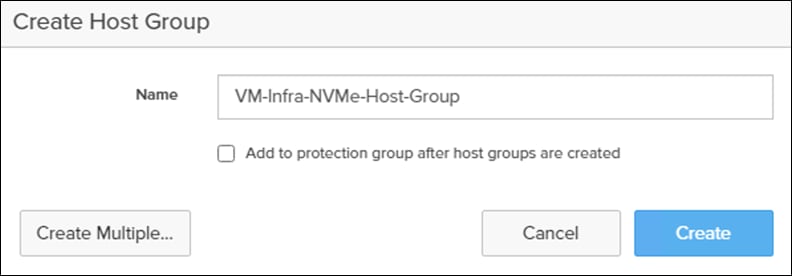
Step 3. Provide a name for the group and click Create.
Step 4. Select the group in the Host Groups Panel.
Step 5. In the Host Group view, select Add… from the Member Hosts menu.
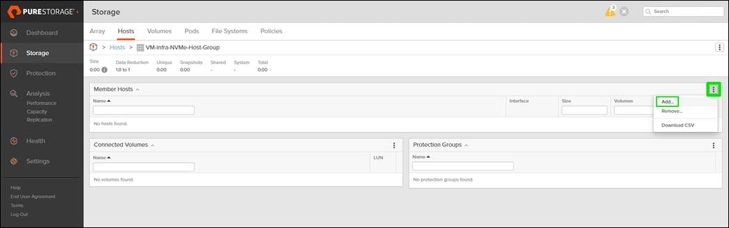
Step 6. Select the host to be part of the host group.
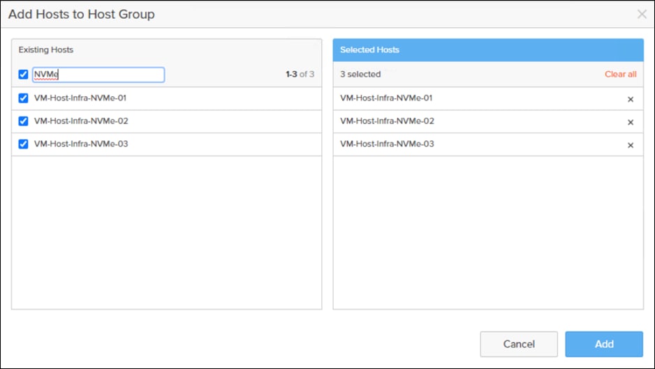
Step 7. Click Add.
Procedure 8. Create NVMe Datastore Volumes for the ESXi Cluster using the Pure Storage Web Portal
Step 1. Click Storage > Volumes.
Step 2. Click the + icon in the Volumes Panel.
A pop-up will appear to create a volume on the FlashArray.
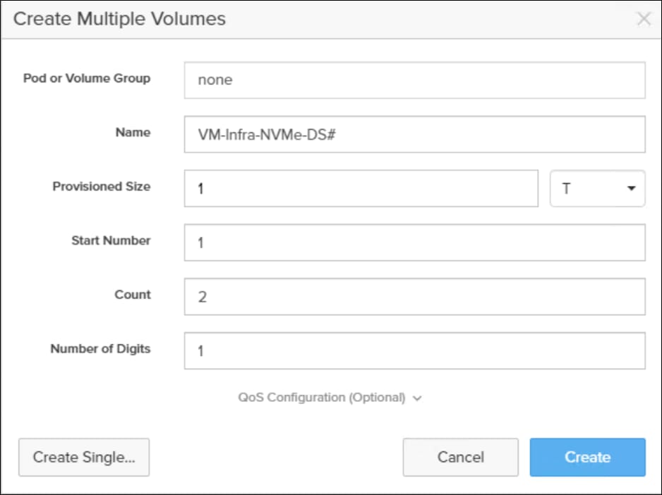
Step 3. Fill in the Name and Provisioned Size.
Step 4. Click Create to provision the volumes to be used as Infra datastore LUN.
Step 5. Return to the Hosts section under the Storage tab. Click ESXi cluster NVMe host group created earlier and select the gear icon drop-down within the Connected Volumes tab within that host group.
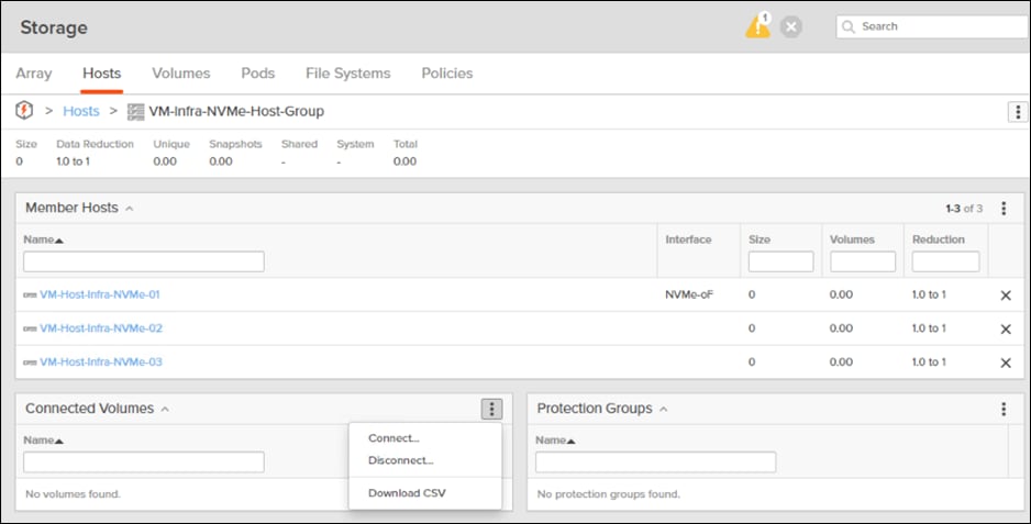
Step 6. Within the drop-down list of the gear icon, select Connect Volumes, and a pop-up will appear.
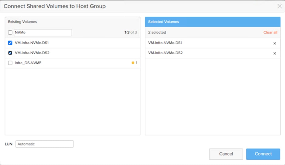
Step 7. Select the Infra datastore NVMe volumes that has been provisioned for the host group, leave the LUN ID for the volume to Automatic, click Connect.
Procedure 9. ESXi Host NVMe over FC Datastore Configuration
Step 1. The remaining steps in the VMware vSphere Client are manual steps that should be completed whether the Ansible configuration or manual configuration is being done. Verify that the NVMe Fibre Channel Disk is mounted on each ESXi host. Under Hosts and Clusters select the ESXi host. In the center pane, select Configure > Storage > Storage Devices. The NVMe Fibre Channel Disk should be listed under Storage Devices. Select the NVMe Fibre Channel Disk, then select Paths underneath. Verify 4 paths have a status of Active (I/O). Repeat this for all 3 hosts.
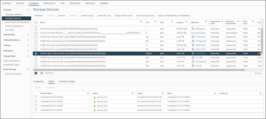
Step 2. For any of the three hosts, right-click the host under Hosts and Clusters and select Storage > New Datastore. Leave VMFS selected and click NEXT.
Step 3. Name the datastore and select the NVMe Fibre Channel Disk. Click NEXT.
Step 4. Leave VMFS 6 selected and click NEXT.
Step 5. Leave all Partition configuration values at the default values and click NEXT.
Step 6. Review the information and click FINISH.
Step 7. Click Storage and select the just-created NVMe datastore. In the center pane, select Hosts. Ensure all three hosts have the datastore mounted.
Procedure 10. ESXi Host Multipathing Configuration
Step 1. From the vCenter management GUI, go to Hosts and Clusters view.
Step 2. Click a Host.
Step 3. Click the Configure tab.
Step 4. Click Storage Devices.
Step 5. Click an NVMe device.
Step 6. Click on Properties.
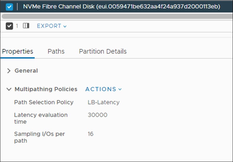
Step 7. Select ACTIONS > Edit Multipathing.
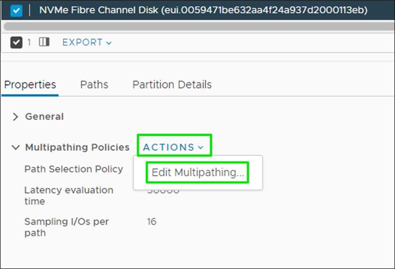
Step 8. Edit as shown below:
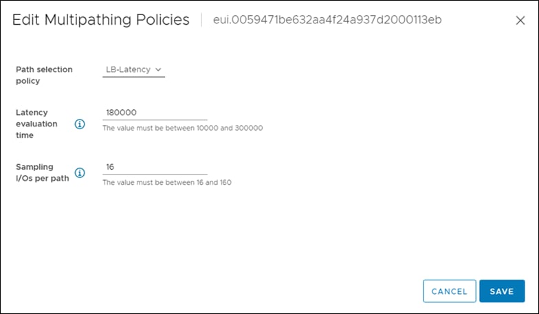
FlashStack Backups
Cisco Intersight SaaS Platform
Cisco Intersight SaaS platform maintains customer configurations online. No separate backup was created for the UCSX configuration.
Basic scheduled backup of the vCenter Server Appliance is available within the native capabilities of the VCSA.
Procedure 1. Create a Scheduled Backup
Step 1. Connect to the VCSA Console here: https://<VCSA IP>:5480 as root.
Step 2. Click Backup in the list to open up the Backup Appliance Dialogue.
Step 3. To the right of the Backup Schedule, click CONFIGURE.
Step 4. Specify the following:
a. The Backup location with the protocol to use [FTPS, HTTPS, SFTP, FTP, NFS, SMB, HTTP]
b. The User name and password.
c. The Number of backups to retain.
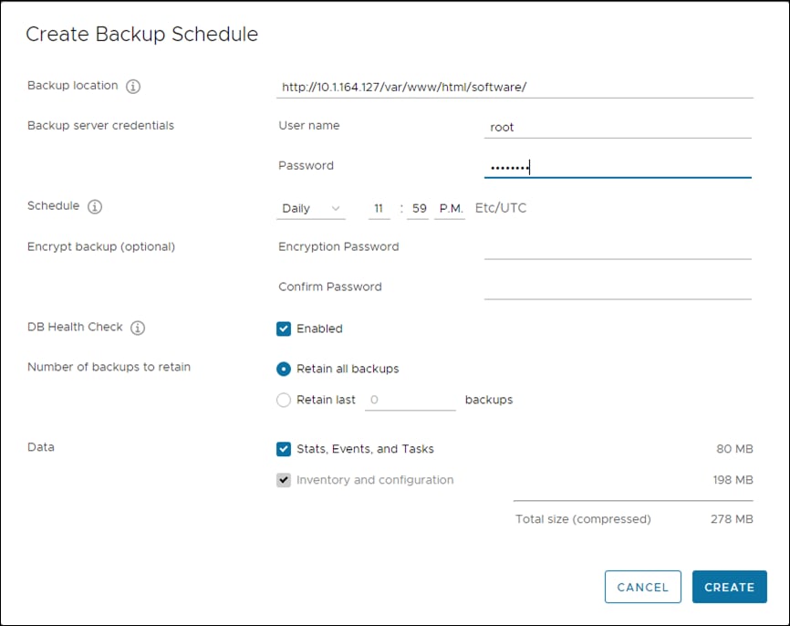
Step 5. Click CREATE.
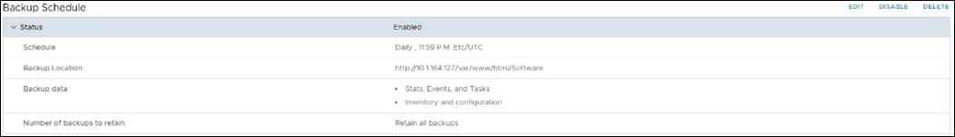
The Backup Schedule displays the Status as Enabled.
Step 6. Restoration can be initiated with the backed-up files using the Restore function of the VCSA 7.0 U2 Installer.
Paniraja Koppa, Technical Marketing Engineer, Cisco Systems, Inc.
Paniraja Koppa works at Cisco’s Cloud and Compute group with a primary focus on data center and cloud technologies. In his current role, he works on design and development, best practices, optimization, automation and technical content creation of compute and hybrid cloud solutions. Prior to this, he has led QA efforts for 4 new virtual adapter cards for Cisco UCS. He also worked as technical consulting engineer in the Data Center Virtualization space. Paniraja holds a master’s degree in Computer Science. He has presented several papers in International Conferences and speaker at events like Cisco Live US and Europe, Open Infrastructure Summit, and other partner events.
Joe Houghes, Senior Solutions Architect, Pure Storage, Inc.
Joe is a Senior Solutions Architect in the Portfolio Solutions team within Pure Storage, focused on solutions on the FlashStack platform along with automation and integration. He has experience from over 15 years in Information Technology across various customer/vendor organizations with architecture and operations expertise covering compute, networking, storage, virtualization, business continuity and disaster recovery, and cloud computing technologies, plus automation and integration across many applications and vendor platforms.
Acknowledgments
For their support and contribution to the design, validation, and creation of this Cisco Validated Design, the authors would like to thank:
● John George, Technical Marketing Engineer, Cisco Systems, Inc.
● Haseeb Niazi, Principal Technical Marketing Engineer, Cisco Systems, Inc.
● Chris O'Brien, Director, UCS Solutions, Cisco Systems, Inc.
● Rohit Mittal, Product Manager, Cisco Systems, Inc.
● Sreeni Edula, Product Manager, Cisco Systems, Inc.
● Eldho Jacob, Technical Marketing Engineer, Cisco Systems, Inc.
● Craig Waters, Technical Director, Pure Storage, Inc.
Appendix
This appendix is organized into the following:
● Compute
● Network
● Storage
GitHub repository for solution deployment: https://github.com/ucs-compute-solutions/FlashStack_IMM_Ansible
Cisco Intersight: https://www.intersight.com
Cisco Intersight Managed Mode: https://www.cisco.com/c/en/us/td/docs/unified_computing/Intersight/b_Intersight_Managed_Mode_Configuration_Guide.html
Cisco Unified Computing System: http://www.cisco.com/en/US/products/ps10265/index.html
Cisco UCS 6536 Fabric Interconnects: https://www.cisco.com/c/en/us/products/collateral/servers-unified-computing/ucs6536-fabric-interconnect-ds.html
Cisco Nexus 9000 Series Switches: http://www.cisco.com/c/en/us/products/switches/nexus-9000-series-switches/index.html
Cisco MDS 9132T Switches: https://www.cisco.com/c/en/us/products/collateral/storage-networking/mds-9100-series-multilayer-fabric-switches/datasheet-c78-739613.html
Pure Storage FlashArray//X: https://www.purestorage.com/products/nvme/flasharray-x.html
Pure Storage FlashArray//XL: https://www.purestorage.com/products/nvme/flasharray-xl.html
VMware vCenter Server: http://www.vmware.com/products/vcenter-server/overview.html
VMware vSphere: https://www.vmware.com/products/vsphere
Cisco UCS Hardware Compatibility Matrix: https://ucshcltool.cloudapps.cisco.com/public/
VMware and Cisco Unified Computing System: http://www.vmware.com/resources/compatibility
Pure Storage Interoperability Matrix. Note, this interoperability list will require a support login form Pure: https://support.purestorage.com/FlashArray/Getting_Started/Compatibility_Matrix
Pure Storage FlashStack Compatibility Matrix. Note, this interoperability list will require a support login from Pure: https://support.purestorage.com/FlashStack/Product_Information/FlashStack_Compatibility_Matrix
For comments and suggestions about this guide and related guides, join the discussion on Cisco Community at https://cs.co/en-cvds.
CVD Program
ALL DESIGNS, SPECIFICATIONS, STATEMENTS, INFORMATION, AND RECOMMENDATIONS (COLLECTIVELY, "DE-SIGNS") IN THIS MANUAL ARE PRESENTED "AS IS," WITH ALL FAULTS. CISCO AND ITS SUPPLIERS DISCLAIM ALL WAR-RANTIES, INCLUDING, WITHOUT LIMITATION, THE WARRANTY OF MERCHANTABILITY, FITNESS FOR A PARTICULAR PURPOSE AND NONINFRINGEMENT OR ARISING FROM A COURSE OF DEALING, USAGE, OR TRADE PRACTICE. IN NO EVENT SHALL CISCO OR ITS SUPPLIERS BE LIABLE FOR ANY INDIRECT, SPECIAL, CONSEQUENTIAL, OR INCIDENTAL DAMAGES, INCLUDING, WITHOUT LIMITATION, LOST PROFITS OR LOSS OR DAMAGE TO DATA ARISING OUT OF THE USE OR INABILITY TO USE THE DESIGNS, EVEN IF CISCO OR ITS SUPPLIERS HAVE BEEN ADVISED OF THE POSSIBILITY OF SUCH DAMAGES.
THE DESIGNS ARE SUBJECT TO CHANGE WITHOUT NOTICE. USERS ARE SOLELY RESPONSIBLE FOR THEIR APPLICA-TION OF THE DESIGNS. THE DESIGNS DO NOT CONSTITUTE THE TECHNICAL OR OTHER PROFESSIONAL ADVICE OF CISCO, ITS SUPPLIERS OR PARTNERS. USERS SHOULD CONSULT THEIR OWN TECHNICAL ADVISORS BEFORE IMPLE-MENTING THE DESIGNS. RESULTS MAY VARY DEPENDING ON FACTORS NOT TESTED BY CISCO.
CCDE, CCENT, Cisco Eos, Cisco Lumin, Cisco Nexus, Cisco StadiumVision, Cisco TelePresence, Cisco WebEx, the Cisco logo, DCE, and Welcome to the Human Network are trademarks; Changing the Way We Work, Live, Play, and Learn and Cisco Store are service marks; and Access Registrar, Aironet, AsyncOS, Bringing the Meeting To You, Catalyst, CCDA, CCDP, CCIE, CCIP, CCNA, CCNP, CCSP, CCVP, Cisco, the Cisco Certified Internetwork Expert logo, Cisco IOS, Cisco Press, Cisco Systems, Cisco Systems Capital, the Cisco Systems logo, Cisco Unified Computing System (Cisco UCS), Cisco UCS B-Series Blade Servers, Cisco UCS C-Series Rack Servers, Cisco UCS S-Series Storage Servers, Cisco UCS Manager, Cisco UCS Management Software, Cisco Unified Fabric, Cisco Application Centric Infrastructure, Cisco Nexus 9000 Series, Cisco Nexus 7000 Series. Cisco Prime Data Center Network Manager, Cisco NX-OS Software, Cis-co MDS Series, Cisco Unity, Collaboration Without Limitation, EtherFast, EtherSwitch, Event Center, Fast Step, Follow Me Browsing, FormShare, GigaDrive, HomeLink, Internet Quotient, IOS, iPhone, iQuick Study, LightStream, Linksys, MediaTone, MeetingPlace, MeetingPlace Chime Sound, MGX, Networkers, Networking Academy, Network Registrar, PCNow, PIX, PowerPanels, ProConnect, ScriptShare, SenderBase, SMARTnet, Spectrum Expert, StackWise, The Fastest Way to Increase Your Internet Quotient, TransPath, WebEx, and the WebEx logo are registered trade-marks of Cisco Systems, Inc. and/or its affiliates in the United States and certain other countries. (LDW_P2)
All other trademarks mentioned in this document or website are the property of their respective owners. The use of the word partner does not imply a partnership relationship between Cisco and any other company. (0809R)