Cisco Multi-Site Deployment Guide for ACI Fabrics
Available Languages
Bias-Free Language
The documentation set for this product strives to use bias-free language. For the purposes of this documentation set, bias-free is defined as language that does not imply discrimination based on age, disability, gender, racial identity, ethnic identity, sexual orientation, socioeconomic status, and intersectionality. Exceptions may be present in the documentation due to language that is hardcoded in the user interfaces of the product software, language used based on RFP documentation, or language that is used by a referenced third-party product. Learn more about how Cisco is using Inclusive Language.
- US/Canada 800-553-2447
- Worldwide Support Phone Numbers
- All Tools
 Feedback
 Feedback
| Date |
Version |
Modifications |
| 10/03/2021 |
1.0 |
● Initial Version
|
| 10/14/2021 |
2.0 |
● Added the “Integrating ACI Multi-Pod and ACI Multi-Site”
● Fixed some typos and other small edits
|
Table 1. Document Version History
Introduction
The main goal of this document is to provide specific deployment and configuration information for multiple Cisco ACI Multi-Site use cases. ACI Multi-Site is the Cisco architecture commonly used to interconnect geographically dispersed data centers and extend Layer 2 and Layer 3 connectivity between those locations, together with a consistent end-to-end policy enforcement.
This paper is not going to describe in detail the functional components of a Cisco Multi-Site architecture, nor the specifics of how data-plane communication works, and the control-plane protocols used for exchanging reachability information between ACI fabrics. A prerequisite for making the best use of this deployment guide is to have gone through the white paper describing the overall ACI Multi-Site architecture and its main functionalities, available at the link below:
This guide is divided into different sections, each tackling a specific deployment aspect:
● Provisioning the Inter-Site Network connectivity: this section covers the specific configuration required on the network devices building the ISN infrastructure used to interconnect the different ACI fabrics.
● Adding ACI fabrics to a specific Multi-Site domain: this part covers the required infra configuration performed on the Cisco Nexus Dashboard Orchestrator NDO (previously known as Cisco Multi-Site Orchestrator – MSO) to add different ACI fabrics to the same Multi-Site domain.
Note: Most of the considerations contained in this paper apply also for deployment leveraging the original virtual NDO cluster (available up to the software release 3.1(1)). However, given the fact that going forward the Orchestrator is only going to be supported as a service enabled on top of Cisco Nexus Dashboard compute platform, in the rest of this document we’ll solely make reference to Nexus Dashboard Orchestrator (NDO) deployments.
● Nexus Dashboard Orchestrator schema and templates definition: this section provides guidelines on how to configure schema and templates in order to provision specific tenant policies. While Nexus Dashboard Orchestrator by design provides lots of flexibility on how to define those policy elements, the goal is to offer some best practice recommendations.
● Establishing endpoint connectivity across sites (east-west): this section focuses on how to deploy EPGs/BDs in different fabrics and establish Layer 2 and Layer 3 intersite connectivity between them. From a security perspective, it is covered how to define specific policies between EPGs with the use of security contracts, but also how to simplify the establishment of connectivity by initially removing the policy aspect through the use of Preferred Groups and vzAny.
● Establishing endpoint connectivity with the external network domain (North-South): this part focuses on the deployment of L3Out configuration to ensure endpoints connected to the ACI leaf nodes of different fabrics can communicate with external resources, either reachable via a local L3Out or a remote L3Out connection (Intersite L3Out).
● Network services integration: the focus here is on how to leverage Service-Graph with PBR to ensure network services can be inserted in between communications for EPGs belonging to the same fabric or to separate fabrics (east-west) or for communication between endpoints connected to ACI and the external network domain (north-south).
The topology that is going to be used to provision the different use cases mentioned above is the one shown in Figure 1 below:
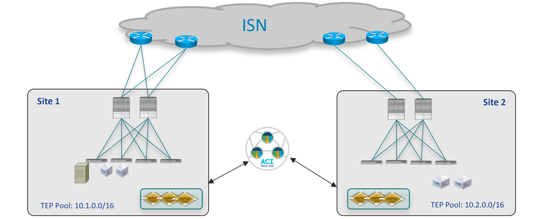
Two Fabrics Multi-Site Deployment
The ACI fabrics are connected via an Inter-Site Network (ISN) routed domain that represents the transport for VXLAN communications happening between endpoints part of different fabrics. As a reminder, there is no latency limit between the different ACI fabrics part of the same Multi-Site domain. The only latency considerations are:
● Up to 150 ms, RTT is the latency supported between the Nexus Dashboard cluster nodes where the Orchestrator service is enabled.
● Up to 500 msec RTT is the latency between each Nexus Dashboard Orchestrator node and the APIC controller nodes that are added to the Multi-Site domain. This means that the Multi-Site architecture has been designed from the ground up to be able to manage ACI fabrics that can be geographically dispersed around the world.
All the use cases described in this paper have been validated using the latest ACI and Nexus Dashboard Orchestrator software releases available at the time of writing this paper. Specifically, the two ACI fabrics are using ACI 5.1(1) code, whereas for Nexus Dashboard Orchestrator it is used the 3.5(1) release. However, keep in mind that from Nexus Dashboard Orchestrator release 2.2(1), there is not interdependency between Nexus Dashboard Orchestrator and ACI software releases, and a Multi-Site deployment using Nexus Dashboard Orchestrator release 3.2(1) (and later) can have fabrics running a mix of software releases (from ACI 4.2(4), which is the first one supported with Nexus Dashboard) being part of the same Multi-Site domain.
Note: The documentation set for this product strives to use bias-free language. For the purposes of this documentation set, bias-free is defined as language that does not imply discrimination based on age, disability, gender, racial identity, ethnic identity, sexual orientation, socioeconomic status, and intersectionality. Exceptions may be present in the documentation due to language that is hardcoded in the user interfaces of the product software, language used based on RFP documentation, or language that is used by a referenced third-party product.
Provisioning Inter-Site Network Connectivity
The first step in the creation of a Multi-Site domain is the provisioning of the network infrastructure used to interconnect the different ACI fabrics and to carry the VXLAN traffic allowing to establish Layer 2 and Layer 3 connectivity across sites. The ISN is not managed by APIC nor by the Orchestrator service, so it must be independently pre-provisioned before starting the configuration of the spine nodes to connect each fabric to the ISN infrastructure.
ISN Router Connecting to the Spine Nodes
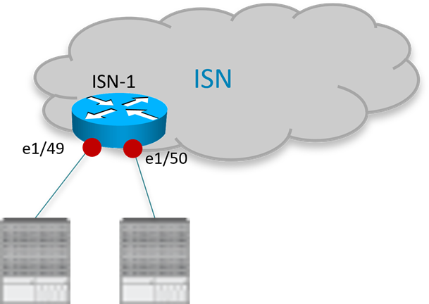
The interfaces of the ISN devices connecting to the spine nodes in each fabric need to be deployed as point-to-point L3 links establishing routing adjacencies to allow for the exchange of infrastructure (i.e., underlay) prefixes between the spine nodes in different fabrics. The configuration sample below shows a specific example of the interfaces defined on the ISN router in Figure 2 to connect to the spine nodes of the local ACI Pod (the interfaces of other routers would be configured similarly).
Note: The configuration below applies to the deployment of Nexus 9000 switches as ISN nodes. When using different HW platforms, it may be required to slightly modify the specific CLI commands.
ISN-1 Router:
interface Ethernet1/49.4
description L3 Link to Pod1-Spine1
mtu 9150
encapsulation dot1q 4
vrf member ISN
ip address 192.168.1.1/31
ip ospf network point-to-point
ip router ospf ISN area 0.0.0.0
no shutdown
!
interface Ethernet1/50.4
description L3 Link to Pod1-Spine2
mtu 9150
encapsulation dot1q 4
vrf member ISN
ip address 192.168.1.5/31
ip ospf network point-to-point
ip router ospf ISN area 0.0.0.0
no shutdown
● As shown above, sub-interfaces must be created on the physical links connecting the router to the spine nodes. This is because of the specific ACI implementation that mandates leaf and spine nodes to always generate dot1q tagged traffic (the specific VLAN tag 4 is always used by the ACI spine nodes when connecting to the external ISN infrastructure). Please notice that those interfaces remain point-to-point Layer 3 links that must be addressed as part of separate IP subnets (the use of a /30 or /31 mask is commonly recommended) and this imply that the main requirement for the ISN router is to be able to use the same VLAN tag 4 on sub-interfaces configured for different local links. Most of the modern switches and routers offer this capability.
● The MTU of the interfaces should account for the extra overhead of VXLAN traffic (50 Bytes). The 9150B value shown in the configuration sample above matches the default MTU of the spine sub-interfaces connecting to the external ISN infrastructure, which ensures that the OSPF adjacency can be successfully established. However, it is not necessarily required to support such a large MTU on the ISN routers for intersite communication, as the required minimum value mostly depends on the MTU of the traffic generated by the endpoints connected to the ACI fabric. For more information on this, please refer to the “Intersite Network (ISN) deployment considerations” section of the ACI Multi-Site paper:
https://www.cisco.com/c/en/us/solutions/collateral/data-center-virtualization/application-centric-infrastructure/white-paper-c11-739609.html#IntersiteNetworkISNdeploymentconsiderations
● The interfaces on the ISN routers can be deployed as part of a dedicated VRF or in the global table. Using a dedicated VRF, when possible, is a strong best practice recommendation, both from an operational simplification perspective and also preventing to send to the spine nodes more prefixes than strictly required for Multi-Site control and data plane (in case the ISN infrastructure is also shared for providing other connectivity services).
● From ACI release 5.2(3) and Nexus Dashboard Orchestrator release 3.5(1) it is possible to deploy also BGP for establishing underlay adjacencies between the spines and the ISN devices. However, in this paper we focus on the use of OSPF as it has been available since the introduction of the ACI Multi-Site architecture, and it is widely deployed.
Very often, a different routing protocol (usually BGP) is used between the devices building the core of the ISN network, especially when that infrastructure extends across geographically dispersed locations. This implies the need to redistribute from OSPF into BGP the specific prefixes that must be exchanged across fabrics part of the same Multi-Site domain. This allows controlling in a very selective way the prefixes that are exchanged across sites. As it will be discussed in more detail as part of the “Nexus Dashboard Orchestrator Sites Infra Configuration” section, only a handful of prefixes are required for establishing intersite control and data plane connectivity:
● A BGP EVPN Router-ID for each spine node, to establish MP-BGP EVPN adjacencies to remote spine nodes.
● An Overlay Unicast TEP (O-UTEP) anycast address for each Pod part of the same ACI fabric, used for unicast Layer 2 and Layer 3 data plane connectivity with the remote sites.
● An Overlay Multicast TEP (O-MTEP) anycast address shared between all the Pods part of the same ACI fabric, used to receive Layer 2 Broadcast/Unknown Unicast/Multicast (BUM) traffic originated from the remote sites.
● One (or more) external TEP pools are used to enable the intersite L3Out connectivity with the remote sites.
The original infra TEP pools used for each fabric bring-up (10.1.0.0/16 and 10.2.0.0/16 in the example in Figure 1) do not need to be exchanged across sites and should hence not being redistributed between protocols. The sample below shows an example of redistribution allowing the exchange of the few prefixes listed above (once again, this configuration applies to Nexus 9000 switches deployed as ISN devices):
● Define the IP prefix list and route-map to advertise the local prefixes to the remote sites:
ip prefix-list LOCAL-MSITE-PREFIXES seq 5 permit <BGP-EVPN-RID Site1-Spine1>
ip prefix-list LOCAL-MSITE-PREFIXES seq 10 permit <BGP-EVPN-RID Site1-Spine2>
ip prefix-list LOCAL-MSITE-PREFIXES seq 15 permit <O-UTEP-Pod1-Site1>
ip prefix-list LOCAL-MSITE-PREFIXES seq 20 permit <O-MTEP-Site1>
ip prefix-list LOCAL-MSITE-PREFIXES seq 25 permit <EXT-TEP-POOL-Site1>
!
route-map MSITE-PREFIXES-OSPF-TO-BGP permit 10
match ip address prefix-list LOCAL-MSITE-PREFIXES
● Define the IP prefix list and route-map to specify the prefixes to be received from the remote sites:
ip prefix-list REMOTE-MSITE-PREFIXES seq 5 permit <BGP-EVPN-RID Site2-Spine1>
ip prefix-list REMOTE-MSITE-PREFIXES seq 10 permit <BGP-EVPN-RID Site2-Spine2>
ip prefix-list REMOTE-MSITE-PREFIXES seq 15 permit <O-UTEP-Pod1-Site2>
ip prefix-list REMOTE-MSITE-PREFIXES seq 20 permit <O-MTEP-Site2>
ip prefix-list REMOTE-MSITE-PREFIXES seq 25 permit <EXT-TEP-POOL-Site2>
!
route-map MSITE-PREFIXES-BGP-TO-OSPF permit 10
match ip address prefix-list REMOTE-MSITE-PREFIXES
● Apply the route-maps to redistribute prefixes between OSPF and BGP (and vice versa):
router bgp 3
vrf ISN
address-family ipv4 unicast
redistribute ospf ISN route-map MSITE-PREFIXES-OSPF-TO-BGP
!
router ospf ISN
vrf ISN
redistribute bgp 3 route-map MSITE-PREFIXES-BGP-TO-OSPF
Adding the ACI Fabrics to the Multi-Site Domain
The following sections describes how to add the fabrics that are part of your Multi-Site domain to the Nexus Dashboard Orchestrator.
Onboarding ACI Fabrics to Nexus Dashboard Orchestrator
Once the configuration in the ISN is provisioned, it is then possible to onboard the ACI fabrics to Nexus Dashboard Orchestrator and perform the required infra configuration to ensure each site can be successfully connected to the ISN and establish the required control plane peerings. Specifically, each spine establishes OSPF adjacencies with the directly connected first-hop ISN routers and MP-BGP EVPN peerings with the spine nodes in the remote sites.
Up to Multi-Site Orchestrator release 3.1(1), the site onboarding procedure had to be done directly on MSO. From release 3.2(1) and later, the Nexus Dashboard Orchestrator is only supported as a service running on a Nexus Dashboard compute cluster and in that case, the site onboarding procedure must be performed directly on Nexus Dashboard (and the sites are then made available to the hosted services, as it is the case for Nexus Dashboard Orchestrator in our specific example). The required infra configuration steps described in the “Nexus Dashboard Orchestrator Sites Infra Configuration” section remain valid also for deployments leveraging older MSO releases.
Figure 3 highlights how to start the process used to onboard an ACI fabric to Nexus Dashboard.

Adding a Site to NDO 3.1(1)
After selecting “Add Site”, the following screen opens up allowing to specify the information for the ACI fabric that needs to be onboarded on NDO.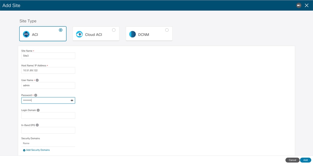
Specify the ACI Fabric Information
The following information is required to onboard an ACI fabric to Nexus Dashboard:
● Site Name: The name used to reference the ACI fabric on Nexus Dashboard.
● Host Name / IP Address: The IP address of one of the APIC cluster nodes managing the fabric that is being added. At the time of writing of this paper, and when running only the Orchestrator service on top of Nexus Dashboard, it is possible to specify here the Out-of-Band (OOB) or In-Band (IB) address of the APIC. When enabling other services on the same ND cluster (as for example Insights), it may be required instead to onboard the fabric using the IB address only, so please refer to the specific service installation guide (available on cisco.com) for more specific information.
● User Name and Password: APIC credentials used to connect to Nexus Dashboard and, through the Single-Signed-On functionality, to the UI of the services hosted on Nexus Dashboard.
● Login Domain: By default, the user will be locally authenticated on Nexus Dashboard. If instead, the desire is to use a specific login domain (Radius, TACACS, etc.), the domain name can be defined on Nexus Dashboard and specified in this field.
● In-Band EPG: this is only required when hosting services on Nexus Dashboard (like Insights) that are using In-Band connectivity for data streaming from this site.
● Security Domains:.
The last optional step of the ACI fabric onboarding process consists in dropping a pin for the site on the map, to represent the geographical location for this specific fabric.
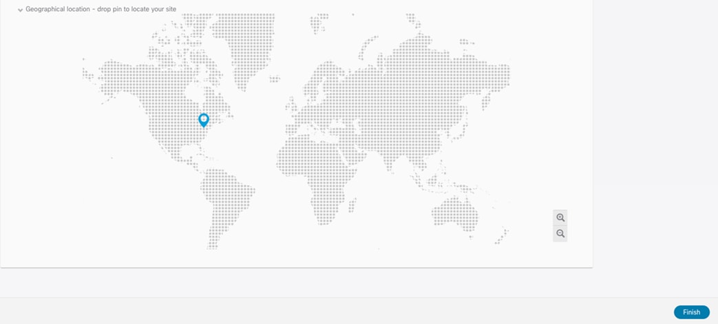
Dropping a Pin on the Map to Locate the Site
The same procedure can be repeated for every fabric that needs to be onboarded to Nexus Dashboard. At the end, all these sites are displayed on the Nexus Dashboard Orchestrator UI in “Unmanaged” state. The user can the selectively set as “Managed” the fabrics that should become part of the same ACI Multi-Site domain.
When a site is set to “Managed”, the user is also asked to enter a specific Site ID, which must uniquely identify that site.
Note: The Site ID is different than the Fabric-ID that is configured at the APIC level. Fabrics configured with the same Fabric-ID can become part of the same multi-Site domain, as long as they get assigned a unique Site ID.
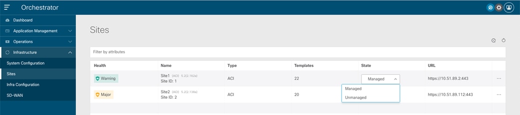
Displaying the Sites on the NDO UI
Once the fabrics become “Managed”, they will be displayed on the NDO Dashboard.
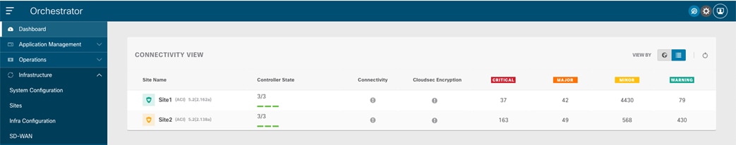
Connectivity View on NDO Dashboard
As noticed above, the Orchestrator Service can gather information about the health of each APIC controller node for the onboarded sites and the specific faults raised on each APIC domain (with their associated level of criticality). The connectivity between sites is showing a warning sign at this point, for the simple reason that the fabrics have just been onboarded to the Orchestrator Service, but the infra configuration steps have not been performed yet to connect each site to the external ISN.
Nexus Dashboard Orchestrator Sites Infra Configuration
After the fabrics have been onboarded to Nexus Dashboard and set as “Managed” on the Orchestrator service, it is required to perform the specific infra configuration allowing to connect each site to the ISN. This is needed so the spines in each fabric can first establish the OSPF adjacencies with the directly connected ISN routers and exchange the ‘underlay’ network information required for then successfully establishing intersite control plane and data plane connectivity.
Table 1 below displays the specific information that should be available before starting the infra configuration. For more explanation about the meaning of those different IP prefixes please refer to the “Intersite Network (ISN) deployment considerations” section of the ACI Multi-Site paper:
https://www.cisco.com/c/en/us/solutions/collateral/data-center-virtualization/application-centric-infrastructure/white-paper-c11-739609.html#IntersiteNetworkISNdeploymentconsiderations
| Site |
Node |
Interfaces to ISN |
IP Address for Interface to ISN |
BGP-EVPN Router-ID |
O-UTEP |
O-MTEP |
| 1 |
Spine-1101 |
e1/63 e1/64 |
192.168.1.0/31 192.168.1.2/31 |
172.16.100.1 |
172.16.100.100 |
172.16.100.200 |
| 1 |
Spine-1102 |
e1/63 e1/64 |
192.168.1.4/31 192.168.1.6/31 |
172.16.100.2 |
172.16.100.100 |
172.16.100.200 |
| 2 |
Spine-2101 |
e1/63 e1/64 |
192.168.2.0/31 192.168.2.2/31 |
172.16.200.1 |
172.16.200.100 |
172.16.200.200 |
| 2 |
Spine-2102 |
e1/63 e1/64 |
192.168.2.4/31 192.168.2.6/31 |
172.16.200.2 |
172.16.200.100 |
172.16.200.200 |
Table 2. IP Address Information for the Infra Configuration of the Sites
The Infra configuration workflow is started by selecting the “Infrastructure” à “Infra Configuration” option on the Nexus Dashboard Orchestrator left tab.

Starting the Sites Infra Configuration Process
After selecting “Configure Infra”, the “Fabric Connectivity Infra” page is displayed to the user.

Infra Configuration General Settings
In the “General Settings” tab we find the “Control Plane Configuration” section allowing us to tune if desired, some default parameters used for the MP-BGP EVPN control plane used between the spines belonging to different fabrics. It is recommended to keep the default values for those parameters in the majority of the deployment scenarios. This applies also to the “BGP Peering Type” option: by default, it is set as “full-mesh”, which essentially means that the spine nodes deployed in different sites establish a full-mesh of MP-BGP EVPN adjacencies between them. This happens independently from the fact that the different sites are part of the same BGP Autonomous System Number (ASN) or not. The alternative option is to select “route-reflector”, which is effective only if the fabrics are part of the same ASN. Notice also that the “Graceful Helper” knob is on by default: this is to enable the BGP Graceful Restart functionality (documented in IETF RFC 4724) allowing a BGP speaker to indicate its ability to preserve its forwarding state during a BGP restart event.
The site infra configuration is instead started by selecting the tab on the left associated with specific fabric.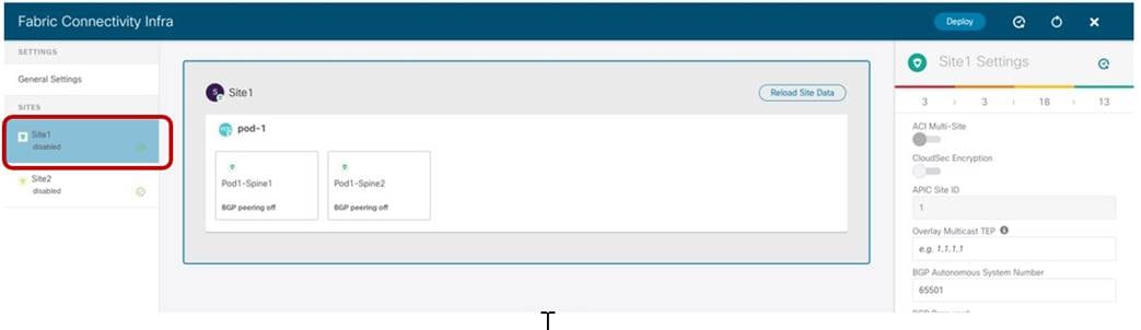
Starting the Specific Site Infra Configuration
The configuration is performed in three different steps: Site level, Pod level and Spine node level, depending on what is being selected on the Nexus Dashboard Orchestrator UI.
Site-Level Configuration
When clicking on the main box identifying the whole ACI Site, The Orchestrator service gives the capability of configuring the parameters shown in Figure 11.
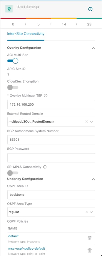
Site Level Configuration
● ACI Multi-Site knob: Turn this on to enable Multi-Site on the fabric and ensure that the control and data plane connectivity with the other sites can be established. This is not required if Nexus Dashboard Orchestrator is deployed only to provide policies locally to each connected site and no intersite communication across the ISN is desired (an ISN is not even needed for this specific scenario).
● Overlay Multicast TEP: The anycast TEP address deployed on all the local spine nodes and used to receive BUM (or Layer 3 multicast) traffic originated from a remote site. A single O-MTEP address is associated with an ACI fabric, no matter if it is a single Pod or a Multi-Pod fabric.
● External Routed Domain: This is the routed domain defined on APIC as part of the Fabric Access policies for connecting the spine nodes to the ISN. While the specification on Nexus Dashboard Orchestrator of this parameter is technically not strictly required, it is a good practice to have the access policies for the spines defined at the APIC level.
● BGP Autonomous System Number: The local ASN value that is dynamically pulled from APIC.
● OSPF settings (Area ID, Area Type, Policies): Those are OSPF parameters required to then establish OSPF adjacencies between the spines and the directly connected ISN routers.
Pod-Level Configuration
Selecting the box identifying a Pod it is then possible to access the Pod’s specific configuration. Those are the settings that are independently applied to all the Pods that are part of the same Multi-Pod fabric (in our specific example we have a single Pod fabric).
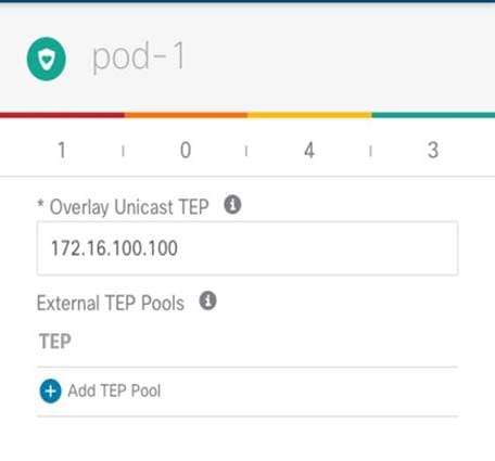
Pod Level Configuration
● Overlay Unicast TEP: The anycast TEP address deployed on all the local spine nodes in the Pod and used to send and receive Layer 2 and Layer 3 unicast traffic flows. Every Pod part of the same Multi-Pod fabric would define a unique TEP address.
● External TEP Pools: Prefix(es) required when enabling the intersite L3Out functionality, as discussed in more detail in the “Deploying Intersite L3Out” section.
Spine-Level Configuration
Finally, a specific configuration must be applied for each specific spine node.
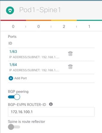
Spine Level Configuration
● Ports: Specify the interfaces on the local spine used to connect to the ISN infrastructure. For each interface, the following parameters must be specified.
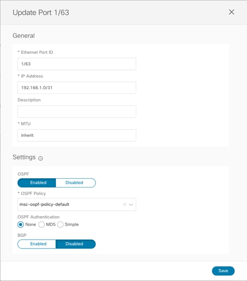
Port Settings
● Ethernet Port ID: The specific interface connected to the ISN. A sub-interface is provisioned to carry send/receive underlay traffic to/from the ISN.
● IP address: The sub-interface’s IP address.
● Description: An optional description to be associated to this specific interface.
● MTU: The MTU value for the sub-interface. “Inherit” keeps the default value of 9150B (as shown in the CLI output below), but the user can specify a different value if desired.
Spine1011-Site1# show int e1/63.63
Ethernet1/63.63 is up
admin state is up, Dedicated Interface, [parent interface is Ethernet1/63
Hardware: 10000/100000/40000 Ethernet, address: 0000.0000.0000 (bia 780c.f0a2.039f)
Internet Address is 192.168.1.0/31
MTU 9150 bytes, BW 40000000 Kbit, DLY 1 usec
It is recommended to ensure the value used here is matching the MTU configured on the ISN router (please refer to the “Provisioning Inter-Site Network Connectivity” section).
● OSPF Policy: References the specific Policy created/selected during the Site level configuration. Usually, it is required to specify the fact that those are OSPF point-to-point interfaces.
● OSPF Authentication: Allows to enable authentication (disabled by default).
Note: The OSPF parameters would disappear if OSPF is disabled and different BGP parameters would be shown when enabling the use of BGP for underlay peering between the spines and the ISN devices.
● BGP Peering: This knob must be enabled to ensure the spine establishes MP-BGP EVPN peerings with the spines in remote fabrics. At least two spines per fabric (for the sake of redundancy) should be configured with this knob enabled. The other local spines assume the role of “Forwarders”, which essentially means they establish MP-BGP EVPN adjacencies only with the spines in other Pods of the same ACI fabric that have “BGP Peering” on and not with the spines deployed in remote ACI fabrics. This can be done to reduce the number of geographic BGP adjacencies, without compromising the overall redundancy of the intersite peerings.
Note: In our specific example of a single-Pod fabric with two spines, it is required to enable the “BGP Peering” knob on both spines, to ensure remote prefixes continue to be learned in case of a spine’s failure scenario. If there were more than two spines deployed in the same Pod, the knob should be enabled only on two of them. The other two “Forwarders” spines would learn the remote endpoint information from the local BGP-enabled spines via the COOP control plane.
● BGP-EVPN ROUTER-ID: Unique loopback interface deployed on each spine and used to establish MP-BGP EVPN peerings with the local “Forwarders” spines and with the BGP enabled spines deployed in the remote sites. The best practice recommendation is to use an IP address dedicated for the purpose of Multi-Site EVPN peerings, which is routable in the ISN infrastructure.
Important Note: The Router-ID specified here for the spine node will replace the original Router-ID that was allocated from the internal TEP pool during the fabric bring-up. This causes a reset of the MP-BGP VPNv4 sessions established between the spine RRs and the leaf nodes to propagate inside the fabric the external prefixes learned on local L3Out connections, with a consequent temporary outage for the north-south traffic flows. As a consequence, it is recommended to perform this infra configuration task one spine at a time and, preferably, during a maintenance window. The same considerations apply to a site removal scenario when a fabric must be detached from Nexus Dashboard Orchestrator. It is worth noticing that simply deleting a site from Nexus Dashboard Orchestrator does not cause the removal of the infra L3Out configuration, so the Router-ID previously assigned on NDO will continue to be used. If, however, the infra L3Out is deleted directly on APIC, the router-ID will be changed to the original one part of the TEP pool, and that would also cause a temporary north-south traffic outage due to the reset of the BGP VPNv4 sessions.
● The last knob is only required if the fabrics in the Multi-Site domain are all part of the same BGP ASN and there is the desire to configure the spine as Route-Reflector. The best practice recommendation is to keep the default behavior of creating full-mesh peerings since there are no scalability concerns even when deploying the maximum number of fabrics supported in the same Multi-Site domain.
Verifying Intersite Control and Data Plane Connectivity
After completing and deploying the configuration steps described in the previous sections for all the ACI fabrics that have been onboarded to Nexus Dashboard Orchestrator, the MP-BGP EVPN adjacencies should be established across sites and the VXLAN dataplane should also be in a healthy state. This can be verified by looking at the dashboard tab of the NDO UI.

NDO Dashboard
If the connectivity were shown in an unhealthy state, the UI would also provide the information if there is a problem in establishing control-plane adjacencies or a non-healthy VXLAN data-plane or both. This information can be retrieved for each site as part of the “Infra Configuration” section, as shown in figure below.

Display Connectivity Status for Each SIte
As noticed above, both the “Overlay Status” and “Underlay Status” of each fabric is shown in detail. The user has also the capability of drilling into more details by clicking the specific value highlighting the routing adjacencies or the tunnel adjacencies. The figure below, shows for example the detailed “Overlay Routing Status” information.
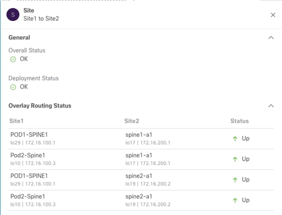
Overlay Routing Status Detailed Information
Typically, issues in the establishment of control plane or data plane connectivity are due to configuration errors in the ISN that do not allow the successful exchange of reachability information between fabrics. The first required step is hence ensuring that the spine nodes in a site receive the IP prefixes (BGP EVPN Router-ID, O-UTEP, and O-MTEP) from the remote site and vice versa. This can be done by connecting to one of the spine nodes in site 1 as follows:
Spine 1101 Site1
Spine1011-Site1# show ip route vrf overlay-1
IP Route Table for VRF "overlay-1"
'*' denotes best ucast next-hop
'**' denotes best mcast next-hop
'[x/y]' denotes [preference/metric]
'%<string>' in via output denotes VRF <string>
<snip>
172.16.100.1/32, ubest/mbest: 2/0, attached, direct
*via 172.16.100.1, lo16, [0/0], 01w02d, local, local
*via 172.16.100.1, lo16, [0/0], 01w02d, direct
172.16.100.2/32, ubest/mbest: 4/0
*via 10.1.0.64, eth1/34.69, [115/3], 06:36:58, isis-isis_infra, isis-l1-int
*via 10.1.0.67, eth1/61.72, [115/3], 06:36:58, isis-isis_infra, isis-l1-int
*via 10.1.0.68, eth1/33.71, [115/3], 06:36:58, isis-isis_infra, isis-l1-int
*via 10.1.0.69, eth1/57.70, [115/3], 06:36:58, isis-isis_infra, isis-l1-int
172.16.100.100/32, ubest/mbest: 2/0, attached, direct
*via 172.16.100.100, lo21, [0/0], 06:36:59, local, local
*via 172.16.100.100, lo21, [0/0], 06:36:59, direct
172.16.100.200/32, ubest/mbest: 2/0, attached, direct
*via 172.16.100.200, lo20, [0/0], 06:36:59, local, local
*via 172.16.100.200, lo20, [0/0], 06:36:59, direct
172.16.200.1/32, ubest/mbest: 1/0
*via 192.168.1.3, eth1/64.64, [110/4], 01w02d, ospf-default, intra
172.16.200.2/32, ubest/mbest: 1/0
*via 192.168.1.1, eth1/63.63, [110/4], 01w02d, ospf-default, intra
172.16.200.100/32, ubest/mbest: 2/0
*via 192.168.1.1, eth1/63.63, [110/4], 06:37:51, ospf-default, intra
*via 192.168.1.3, eth1/64.64, [110/4], 00:00:35, ospf-default, intra
172.16.200.200/32, ubest/mbest: 2/0
*via 192.168.1.1, eth1/63.63, [110/4], 06:37:46, ospf-default, intra
*via 192.168.1.3, eth1/64.64, [110/4], 00:00:35, ospf-default, intra
Nexus Dashboard Orchestrator Tenant, Schema and Template Definition
Once the site onboarding and the infra configuration steps are completed, it is possible to start establishing secure communication between endpoints connected to the different ACI fabrics. To do that it is first necessary to create a Tenant and deploy it on all the fabric that requires intersite connectivity. By default, only two tenants (infra and common) are pre-defined on Nexus Dashboard Orchestrator and automatically associated to all the sites that were previously set as “Managed”.
Notice that there are no schemas associated to those tenants by default, so if it is desirable to utilize some of the common/infra policies that are normally available by default on APIC, it is required to import those objects from the different APIC domains into Nexus Dashboard Orchestrator. Covering the import of existing policies from the APIC domains is out of the scope of this paper.
The focus for the rest of this section is on the creation of policies for new tenants and their provisioning across the fabrics that are part of the Multi-Site domain. The first step in doing so is to create a new Tenant and associate it to all the sites where it should be deployed (Figure 18).

Adding a New Tenant
After selecting the “Add Tenant” option, it is possible to configure the tenant’s information and specify the sites where the tenant should be created. In the example in Figure 19 the newly created tenant is mapped to both the sites that were previously onboarded on the Orchestrator Service.

Mapping a Tenant to Different Fabrics
Notice also how the screen above gives you the possibility of associating specific users to this newly created tenant to allow them to manage the tenant’s configuration (by default only the admin user is associated to the tenant). For more information on the supported user roles and configuration, please refer to the configuration guide at the link below:
As a result of the configuration shown above, Tenant-1 is created on both Site1 and Site2. However, this is still an “empty shell,” as no policies have been defined yet for this tenant to be provisioned on the fabrics. The definition of tenant policies requires the creation of specific configuration constructs called “Schemas” and “Templates.” For a more detailed discussion on what those constructs represent and associated deployment guidelines, please refer to the “Cisco ACI Multi-Site Architecture” section of the paper below:
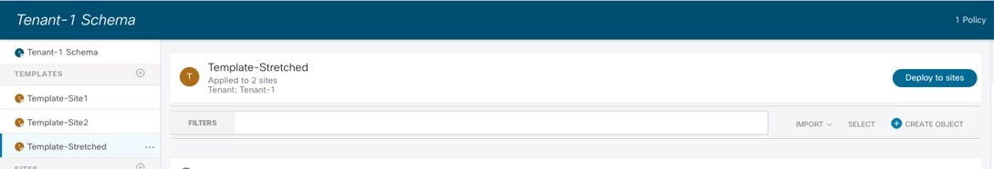
In our example we are going to define a specific schema (named “Tenant-1 Schema”) to be used as a repository of all the templates associated to Tenant-1.

Creating a New Schema
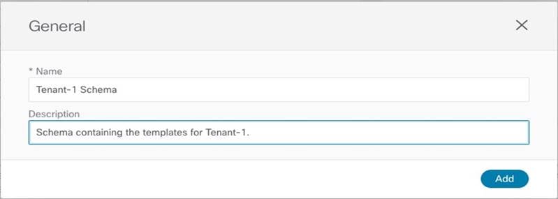
Assigning the Name to the Schema
Since for the use cases we are going to discuss in the rest of this paper we would need to deploy policies that are locally available in each site and common to both sites (i.e., ‘stretched’ policies), we are simply going to use three templates:
● Template-Site1 to deploy policies only local to Site1.
● Template-Site2 to deploy policies only local to Site2.
● Template-Stretched to deploy policies common to Site1 and Site2 (stretched policies).
Note: It is important to keep in mind that objects that should exist in different fabrics part of the same ACI Multi-Site domain, when having the same name should always and only be provisioned from templates associated to all those sites. The only exception could be EPGs deployed as part of different Application Profiles, which could have overlapping names. Even in this case, the best practice recommendation is to provision site local EPGs with unique naming, for the sake of operational simplification.
Each of the above templates must be associated to the Tenant-1 tenant, as shown in Figure 22.

Create a Template Mapped to Tenant-1
Once the same operation has been completed for the other templates, it is then possible to associate each template to the corresponding ACI site.

Associate the Templates to the ACI Sites
When this last step is completed, we are ready to start defining the specific configuration policies to be pushed to the different sites to implement the different use cases described in the following sections.
Intersite Connectivity Between Endpoints
The first two use cases that we are considering are the ones allowing to establish intra-EPG and inter-EPGs connectivity between endpoints connected to separate fabrics. We usually refer to those use cases as “east-west” connectivity.
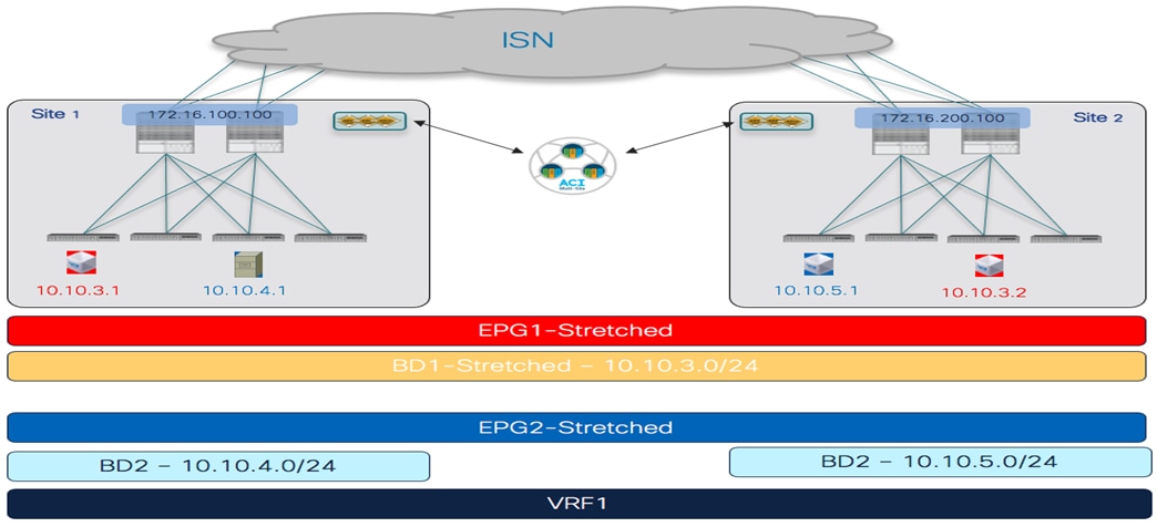
Intra-EPG Connectivity Across Sites
To establish intra-EPG connectivity across sites, it is required to define objects in the Template-Stretched, which allows to render those items in both fabrics. There are a couple of different scenarios that can be deployed. The first one is the one shown in Figure 24, where the EPG is mapped to a stretched BD and the IP subnet(s) associated to the BD is also stretched across sites. This implies that intra-subnet communication can in this case be enabled between endpoints connected to different sites.
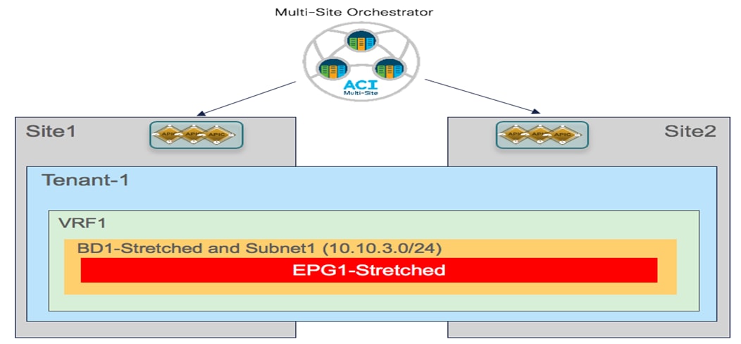
Stretched EPG, Stretched BD and Stretched Subnet
The second scenario is instead depicted in Figure 25. In this case the EPG is still stretched across site, but the BD and the subnet(s) are not stretched, which essentially implies that intra-EPG communication between endpoint connected in separate sites will be Layer 3 and not Layer 2 (as it was in the previous case).
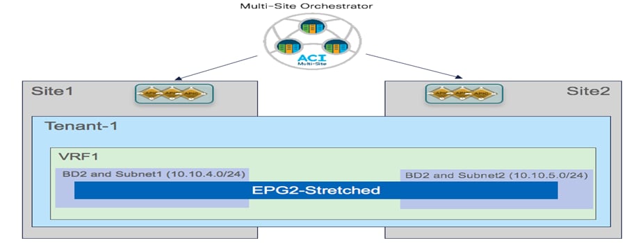
Stretching the EPG without Stretching BD and Subnet
The following sections highlight the specific configuration steps required to provision the policies required to enable the two communication patterns shown above.
Creating a Stretched VRF
The first step for enabling intra-EPG communication across sites consists in creating and deploying the VRF to which the EPG (or better its BD) is associated. This VRF must be configured as part of the Template-Stretched since its configuration must be provisioned in both ACI fabrics.

Creating a new VRF in Template-Stretched
Figure 27 highlights the various configuration parameters available when creating a new VRF on the NDO GUI.
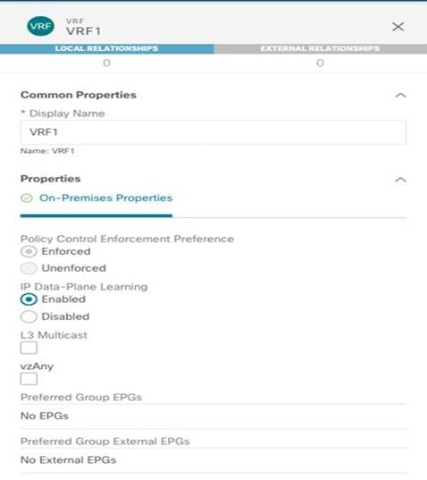
VRF Configuration Parameters
The “Policy Control Enforcement Preference” is always enforced and grayed out, as it is the only VRF configuration supported with Multi-Site. The only reason for exposing the knob is for brownfield scenario where a VRF configuration is imported from APIC into Nexus Dashboard Orchestrator; if the VRF on APIC is configured as “Unenforced”, the user can then have the capability to modify the settings to “Enforced” directly on NDO or keeping it “Unenforced” with the specific understanding that such configuration would not allow establishing intersite communication. There are other supported functionalities (i.e. use of Preferred Groups or vzAny) allowing to remove the policy enforcement for inter-EPG communication, as it will be discussed in more detail in the “Inter-EPGs Connectivity across Sites” section.
The other default setting for a newly created VRF is the enablement of “IP Data-Plane Learning”. There are only specific scenarios where this setting requires to be changed, usually related to use cases where an IP address may get associated with different MAC addresses (active/active server NIC teaming options, application clustered services, certain FW/SLB cluster options, etc.). For more information on this please refer to the ACI design guide available at the link below:
Once the VRF configuration is completed, it is possible to deploy the template to ensure that the VRF is created on both APIC domains that are associated with the Template-Stretched.
Deploying the Template-Stretched to Create the VRF on the APIC Domains
Before the configuration is pushed to the APIC domains, the NDO GUI provides a summary of the objects that will be created and where (in this case only VRF1 on both Site1 and Site2).

VRF1 being pushed to Site1 and Site2
Starting from NDO release 3.4(1), a new functionality named “Template Deployment Plan” became available. By selecting the corresponding button shown in the figure above, graphical (and XML based) information is displayed to show in detail what objects are provisioned by the Orchestrator (and in which sites) as a result of the deployment of the template. In this simple scenario, the Deployment Plan only shows that the VRF has been created in both sites (since the template that is being deployed is associated to both sites).

Template Deployment Plan (Graphical View)
Selecting the “View Payload” option shown above allows you instead to view the XML format of the REST API call that the Orchestrator will make to the APIC controllers in each site as a result of the deployment of the template.
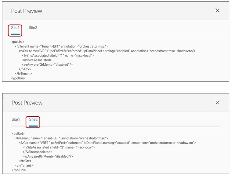
Deployment Plan (XML View)
Creating a Stretched Bridge Domain and a Stretched Subnet
The stretched BD required to implement the use case shown in previous Figure 24 must be defined inside the Template-Stretched.

Creating a Stretched BD in Template-Stretched

Stretched BD (configuration parameters)
● As noticed in Figure 33 above, the BD must be associated with the stretched VRF1 previously defined.
● The BD is stretched by setting the “L2 Stretch” knob. In most of the use cases, the recommendation is to keep the “Intersite BUM Traffic Allow” knob disabled instead, as it is strictly required only in specific scenarios where flooding should be enabled between sites. This is the case for example for legacy-to-ACI migration use cases (until the default gateway for the endpoints is migrated to ACI) or for deployment where L2 multicast stream must be sent across sites. The other knobs to control flooding can usually be kept to the default values.
● Since the BD is stretched, the BD subnet is also defined at the template level since it must also be extended across sites.
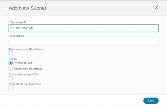
Define the BD’s Subnet IP Address
Once the BD configuration is completed, it is possible to deploy the Template-Stretched to the ACI fabrics.

Deploying the Stretched BD to Site 1 and Site2
As the end results, the BD is created on both APIC domains, with the same anycast gateway 10.10.3.254/24 defined on all the leaf nodes where VRF1 is deployed.
BD-Stretched with Stretched Subnet Created on APIC in Site1
Creating a Non-Stretched Bridge Domain with a Non-Stretched Subnet
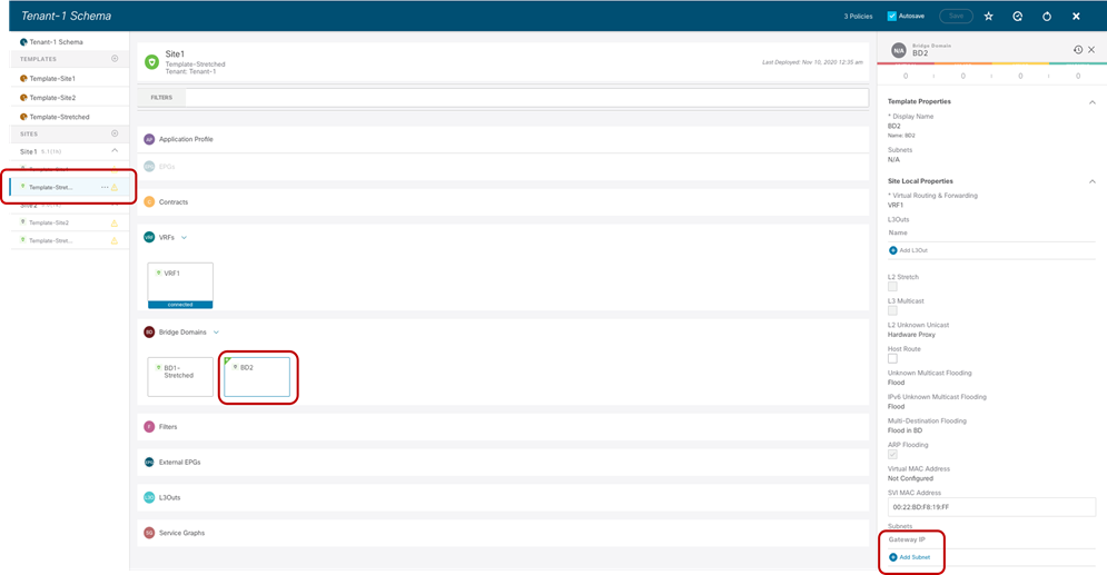
This specific configuration is required to implement the use case previously shown in Figure 25, where the EPG is stretched but the BD is not. Since an EPG can only be associated with a single BD, we need to ensure that the same BD object is created in both sites, even if the forwarding behavior of the BD is to be non-stretched. This can be achieved by deploying the BD inside the Stretched-Template and configure it as shown in Figure 37.

Non-Stretched BD2 Deployed Across Sites (Configuration Parameters)
● The BD is associated with the same stretched VRF1 previously defined.
● The BD must be configured with the “L2 Stretch” knob disabled, as we don’t want to extend the BD subnet nor allow L2 communication across sites.
● The BD’s subnet field is grayed out at the template level; this is because for this specific use case the goal is to provide a separate IP subnet to the BD deployed in each site. The subnet is hence configured at the site level (for each site to which the Template-Stretched is associated), as shown in Figure 38 and Figure 39.
Define the BD’s Subnet at the Site1 Level
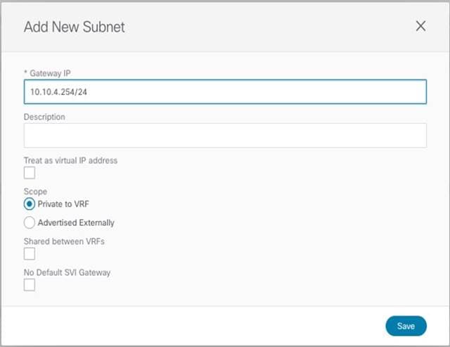
BD’s Subnet for Endpoints Connected to Site1
The same configuration should be applied for the same BD at the Site2 level, which allows to configure a separate IP subnet to be used for the endpoints that are connected to Site2 (Figure 40).
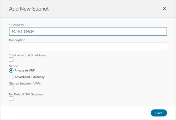
BD’s Subnet for Endpoints Connected to Site2
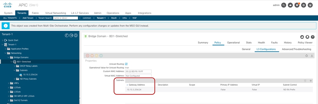
Once a specific subnet has been provisioned at the site level for each ACI fabric and the template has been deployed, it is possible to verify directly on the APIC domains what is the result of the configuration. As noticed in Figure 41, the BD in Site1 is configured with both IP subnets, but only the specific one that was configured at the Site1 level on Nexus Dashboard Orchestrator (10.10.4.0/24) is going to be used to provide default gateway services for the endpoints. The other IP subnet (10.10.5.0/24) (also referred to as “Shadow Subnet”) is automatically provisioned with the “No Default SVI Gateway” parameter since it is only installed on the leaf nodes in Site1 to allow routing to happen across the sites when endpoints part of the same EPG want to communicate (we’ll look at the leaf node routing table in the “Creating the Stretched EPGs” section).

BD’s Subnets Configured on APIC in Site 1
The exact opposite considerations are instead valid for the same BD deployed on the APIC nodes in Site2, as highlighted in Figure 42 below.

BD’s Subnets Configured on APIC in Site 1
Note: The “Shadow Subnet” is always provisioned with the “Private to VRF” scope, independently from the specific settings the same subnet had in the original site. This means that it won’t ever be possible to advertise the “Shadow Subnet” prefix out of an L3Out in the site where it is instantiated. For advertising a BD subnet out of the L3Outs of different sites it is required to deploy the BD with the “L2 Stretch” flag set.
Creating the Stretched EPGs
The last step consists in creating the two EPGs (EPG1-Stretched and EPG2-Stretched) previously shown in Figure 24 and Figure 25. Since those are stretched objects, they will be defined in the Template-Stretched and then pushed to both ACI sites.

Creating Stretched EPGs
As shown above, each EPG is mapped to the BD previously created, depending on the specific use case it needs to be implemented. Once the EPGs have been created, the next logical step is to specify what type of endpoints should become part of those EPGs. ACI allows connecting to the same EPG endpoints of different nature: bare metal servers, virtual machines, containers, etc. The type of endpoints to be used is specified by mapping the EPG to a specific domain (physical domain, VMM domain, etc.). Those domains are created at the APIC level for each fabric that is part of the Multi-Site domain, but they then get exposed to the Orchestrator Service so that the EPG-domain mappings can be provisioned directly through the Orchestrator Service (at the site-specific level, since each fabric can expose its own locally defined domains).
Note: How to create domains on APIC is out of the scope of this paper. For more information, please refer to the ACI configuration guides below:
Figure 44 shows the example of the mapping of EPG2-Stretched to a physical domain in Site1 and the corresponding static port configuration required for those physical endpoints. This configuration must be performed at the site level since it specifically references a physical domain that is locally defined in that APIC domain.
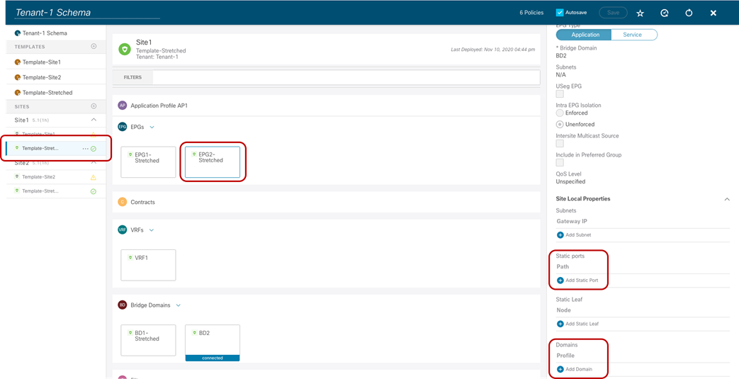
Static Port and Physical Domain Configuration for EPG2-Stretched
After selecting “Add Domain”, is it then possible to specify the specific physical domain this EPG should be mapped to. There are different options to select for what concerns the “Deployment Immediacy” and “Resolution Immediacy”. For more information on what is the meaning of those options please refer to the ACI configuration guides referenced above.
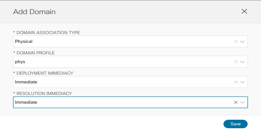
Mapping EPG2-Stretched to a Physical Domain
The static port configuration allows then to specify the specific port (vPC1) and VLAN encapsulation (VLAN 100) to be used to connect the physical endpoint to the ACI fabric and make it part of the EPG2-Stretched group.
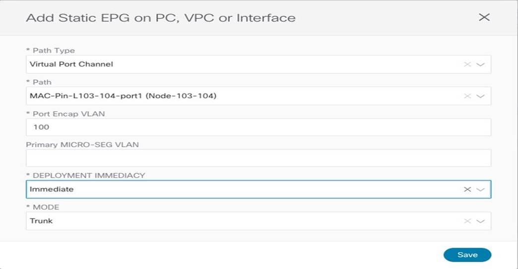
Static Port Configuration for a Physical Endpoint
Finally, before the physical domain mapping configuration is pushed to the APIC Site1, the Nexus Dashboard Orchestrator GUI displays the specific changes that will be applied when hitting “Deploy”, just to ensure the admin can verify those actions reflect the desired intent.
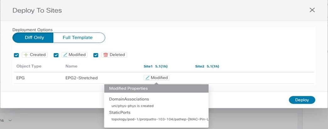
Reviewing the Changes to be Deployed to Site1
Following a similar procedure, it is possible to map EPG2-Stretched to a specific domain in Site2, for example, a VMM domain. Doing so, would then automatically provision a corresponding port-group on the ESXi hosts managed by the vSphere server that is peered with APIC so that the virtual machines that represent endpoints part of Stretched-EPG2 can be connected to it.
Verifying Intra-EPG Communication
Once the endpoints are connected, they are locally discovered by the leaf nodes.
Endpoints Connected to Stretched EPGs
This information can be retrieved directly from the APIC in each site (as part of the operational tab of the EPG), and also through the CLI on each specific leaf node, as shown below for Site1 and Site2:
Leaf 103 Site1
Leaf103-Site1# show endpoint vrf Tenant-1:VRF1
Legend:
s - arp H - vtep V - vpc-attached p - peer-aged
R - peer-attached-rl B - bounce S - static M - span
D - bounce-to-proxy O - peer-attached a - local-aged m - svc-mgr
L - local E - shared-service
+--------------------------------+---------------+-----------------+--------------+-------------+
VLAN/ Encap MAC Address MAC Info/ Interface
Domain VLAN IP Address IP Info
+--------------------------------+---------------+-----------------+--------------+-------------+
10 vlan-100 0050.56b9.3e72 LV po1
Tenant-1:VRF1 vlan-100 10.10.4.1 LV po1
Leaf 301 Site2
Leaf301-Site2# show endpoint vrf Tenant-1:VRF1
Legend:
s - arp H - vtep V - vpc-attached p - peer-aged
R - peer-attached-rl B - bounce S - static M - span
D - bounce-to-proxy O - peer-attached a - local-aged m - svc-mgr
L - local E - shared-service
+--------------------------------+---------------+-----------------+--------------+-------------+
VLAN/ Encap MAC Address MAC Info/ Interface
Domain VLAN IP Address IP Info
+--------------------------------+---------------+-----------------+--------------+-------------+
42 vlan-136 0050.5684.48b0 LpV po2
Tenant-1:VRF1 vlan-136 10.10.5.1 LpV po2
Communication between those endpoints can be freely established across sites since they are part of the same EPG2-Stretched group. When looking at the routing table of the leaf nodes where the endpoints are connected, it is possible to notice how the IP subnet for the local endpoint is locally instantiated (with the corresponding anycast gateway address) and also the IP subnet for the endpoints in the remote site is locally instantiated pointing to the proxy-VTEP address of the local spines as next-hop (10.1.112.66).
Leaf 103 Site1
Leaf103-Site1# show endpoint vrf Tenant-1:VRF1
IP Route Table for VRF "Tenant-1:VRF1"
'*' denotes best ucast next-hop
'**' denotes best mcast next-hop
'[x/y]' denotes [preference/metric]
'%<string>' in via output denotes VRF <string>
10.10.4.0/24, ubest/mbest: 1/0, attached, direct, pervasive
*via 10.1.112.66%overlay-1, [1/0], 00:09:58, static, tag 4294967294
10.10.4.254/32, ubest/mbest: 1/0, attached, pervasive
*via 10.10.4.254, vlan10, [0/0], 00:09:58, local, local
10.10.5.0/24, ubest/mbest: 1/0, attached, direct, pervasive
*via 10.1.112.66%overlay-1, [1/0], 00:09:58, static, tag 4294967294
This is the result of the configuration pushed to APIC and shown in previous Figure 41 (the opposite configuration is provisioned on the leaf nodes in Site2); the subnet entry in the routing table is used to forward routed traffic across sites until the leaf nodes can learn the specific IP address of the remote endpoints via data plane learning.
The CLI output below shows instead the endpoint tables on the leaf node in Site1 once the data plane learning of the remote endpoint in Site2 has happened (similar output would be obtained for the leaf node in Site2). The next-hop of the VXLAN tunnel to reach the remote endpoint is represented by the O-UTEP address of the remote fabric (172.16.200.100).
Leaf 103 Site1
Leaf103-Site1# show endpoint vrf Tenant-1:VRF1
Legend:
S - static s - arp L - local O - peer-attached
V - vpc-attached a - local-aged p - peer-aged M - span
B - bounce H - vtep R - peer-attached-rl D - bounce-to-proxy
E - shared-service m - svc-mgr
+-----------------------------------+---------------+-----------------+--------------+-------------+
VLAN/ Encap MAC Address MAC Info/ Interface
Domain VLAN IP Address IP Info
+-----------------------------------+---------------+-----------------+--------------+-------------+
Tenant-EFT:VRF1 10.10.5.1 tunnel39
13 vlan-883 0050.56b9.1bee LV po1
Tenant-EFT:VRF1 vlan-883 10.10.4.1 LV po1
Leaf 103 Site1
Leaf103-Site1# show interface tunnel 39
Tunnel39 is up
MTU 9000 bytes, BW 0 Kbit
Transport protocol is in VRF "overlay-1"
Tunnel protocol/transport is ivxlan
Tunnel source 10.1.0.68/32 (lo0)
Tunnel destination 172.16.200.100/32
Similarly, communication can be freely achieved between endpoints connected to the EPG1-Stretched group. The only difference is that those endpoints are part of the same IP subnet (10.10.3.254/24) that is stretched across sites. As a consequence, Layer 2 bridging and not Layer 3 routing is what allows to establish communication between them, as it can be noticed by looking at the endpoint table below:
Leaf 101 Site1
Leaf101-Site1# show endpoint vrf Tenant-1:VRF1
Legend:
s - arp H - vtep V - vpc-attached p - peer-aged
R - peer-attached-rl B - bounce S - static M - span
D - bounce-to-proxy O - peer-attached a - local-aged m - svc-mgr
L - local E - shared-service
+--------------------------------+---------------+-----------------+--------------+-------------+
VLAN/ Encap MAC Address MAC Info/ Interface
Domain VLAN IP Address IP Info
+--------------------------------+---------------+-----------------+--------------+-------------+
1/Tenant-1:VRF1 vxlan-16154555 0050.56a2.380f tunnel26
3 vlan-886 0050.56b9.54f3 LV po1
In this case, only the MAC addresses of the remote endpoint is learned on the local leaf node, together with the information that it is reachable through a VXLAN tunnel (tunnel26). Not surprisingly, the VXLAN tunnel is established also in this case between the VTEP of the local leaf node and the O-UTEP address of Site2 (172.16.200.100).
Leaf 101 Site1
Leaf101-Site1# show interface tunnel 26
Tunnel26 is up
MTU 9000 bytes, BW 0 Kbit
Transport protocol is in VRF "overlay-1"
Tunnel protocol/transport is ivxlan
Tunnel source 10.1.0.68/32 (lo0)
Tunnel destination 172.16.200.100/32
As you may have noticed, no specific security policy was required to enable communication between endpoints part of the same EPG. This is the default behavior for ACI, which will always allow free intra-EPG communication. Communication between endpoints part of EPG1-Stretched and EPG2-Stretched won’t instead be allowed by default, because of the zero-trust security approach delivered by ACI. The “Inter-EPG Connectivity across Sites” section will cover in great detail how this communication can be allowed.
Verifying Namespace Translation Information for Stretched Objects
The ACI Multi-Site architecture allows to interconnect sites representing completely different namespaces, since policies are locally instantiated by different APIC clusters. This essentially means that when specific resources (like L2VLAN IDs for BDs, L3VLAN IDs for VRFs, Class-IDs for EPGs) are assigned by each APIC controller, their values would be different in each site even if the objects are stretched across sites (and hence represent the same logical items).
Since VXLAN traffic used to establish intersite communication carries this type of information in the VXLAN header, a translation (or namespace normalization) function must be performed on the receiving spine to ensure successful end-to-end communication and consistent policy application.
Note: The namespace normalization function is not required only for stretched objects, but also when creating relationships between local objects defined in different sites. for more information, please refer to the “Cisco ACI Multi-Site architecture” section of the paper below:
For our specific scenario of inter-site intra-EPG communication, we can then verify how the translation entries are properly configured on the spine nodes receiving VXLAN traffic from the remote site. Figure 49 shows the specific values assigned to the stretched objects created in the APIC domain of Site1.

Class IDs, Segment IDs and Scopes for Objects Created on Site1
Figure 50 displays instead the values for the same objects assigned by the APIC controller in Site2.


Class IDs, Segment IDs and Scopes for Objects Created on Site2
As it can be easily noticed comparing the information in the two figures above, the values assigned to the stretched objects (EPG, BD, or VRF) in Site1 differ from the values provisioned in Site2. This is where the translation function performed by the spine comes into the picture to “normalize” those values and allow successful data plane connectivity across sites.
The outputs below show the entries on the spines of Site1 and a spine of Site 2 that allow translating the Segment ID and Scope of the BD and VRF that are stretched across sites. You can notice how translation mappings are created for VRF1 and BD1-Stretched since those are stretched objects, but not for BD2 that is not “L2 stretched” instead.
Spine 1101 Site1
Spine1101-Site1# show dcimgr repo vnid-maps
--------------------------------------------------------------
Remote | Local
site Vrf Bd | Vrf Bd Rel-state
--------------------------------------------------------------
2 2359299 | 3112963 [formed]
2 2359299 16252857 | 3112963 16154555 [formed]
Spine 401 Site2
APIC-Site2# fabric 401 show dcimgr repo vnid-maps
----------------------------------------------------------------
Node 401 (spine1-a1)
----------------------------------------------------------------
--------------------------------------------------------------
Remote | Local
site Vrf Bd | Vrf Bd Rel-state
--------------------------------------------------------------
1 3112963 | 2359299 [formed]
1 3112963 16154555 | 2359299 16252857 [formed]
The outputs below display instead the translation entries on the spine nodes in Site1 and Site2 for the policy information (i.e., class IDs) of the VRF, BDs, and EPGs. It is worth noticing how in a case (for VRF1) the local and remote class ID values are actually the same (49153). In other cases, the same class ID value is used in the two fabrics for different purposes: for example, 49154 represents the class ID of EPG2-Stretched in Site1 and also the class ID of EPG1-Stretched in Site2. This reinforces the point that each APIC domain assigns values with local significance and hence the namespace normalization function is needed to allow successful intersite communication.
Spine 1101 Site1
Spine1101-Site1# show dcimgr repo sclass-maps
----------------------------------------------------------
Remote | Local
site Vrf PcTag | Vrf PcTag Rel-state
----------------------------------------------------------
2 2916358 16386 | 2129927 32770 [formed]
2 2818056 16387 | 2916360 16386 [formed]
2 2359299 49155 | 3112963 49154 [formed]
2 2359299 49153 | 3112963 49153 [formed]
2 2359299 49154 | 3112963 16387 [formed]
Spine 401 Site2
Spine401-Site2# show dcimgr repo sclass-maps
----------------------------------------------------------
Remote | Local
site Vrf PcTag | Vrf PcTag Rel-state
----------------------------------------------------------
1 3014657 32770 | 2326532 16386 [formed]
1 2916360 16386 | 2818056 16387 [formed]
1 3112963 49154 | 2359299 49155 [formed]
1 3112963 16387 | 2359299 49154 [formed]
1 3112963 49153 | 2359299 49153 [formed]
Inter-EPG Connectivity Across Sites (Intra-VRF)
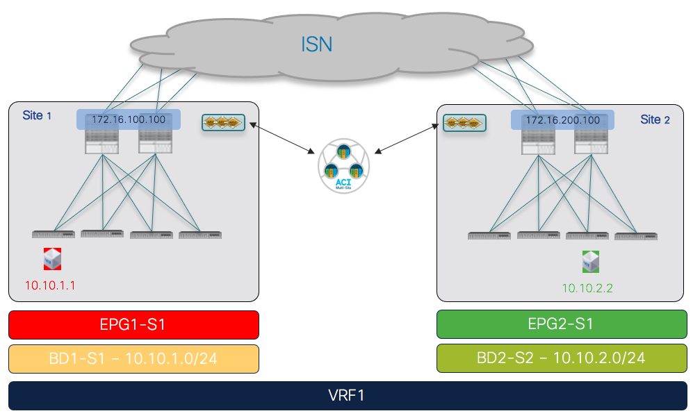
The first use case to consider for the establishment of intersite connectivity between endpoints connected to different EPGs is the one displayed in Figure 51, which applies to the intra-VRF scenario.
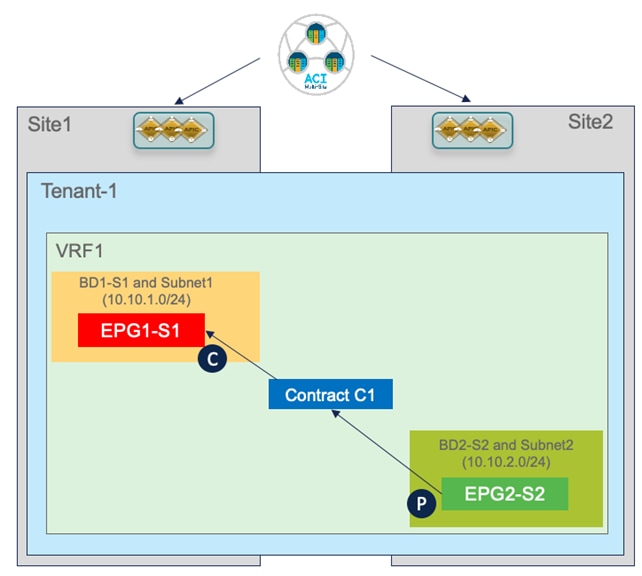
Inter-EPGs Connectivity Across Sites (Intra-VRF) Use Case
Differently from the stretched EPG use cases previously described, in this case, the EPG/BD objects are locally provisioned in each site and connectivity between them must be established by creating a specific security policy (i.e., contract) specifying what type of communication is allowed. It is worth noticing that similar considerations to what is described in the following section would apply for establishing connectivity between EPGs, independently from the fact that they are locally deployed or stretched (Figure 52).
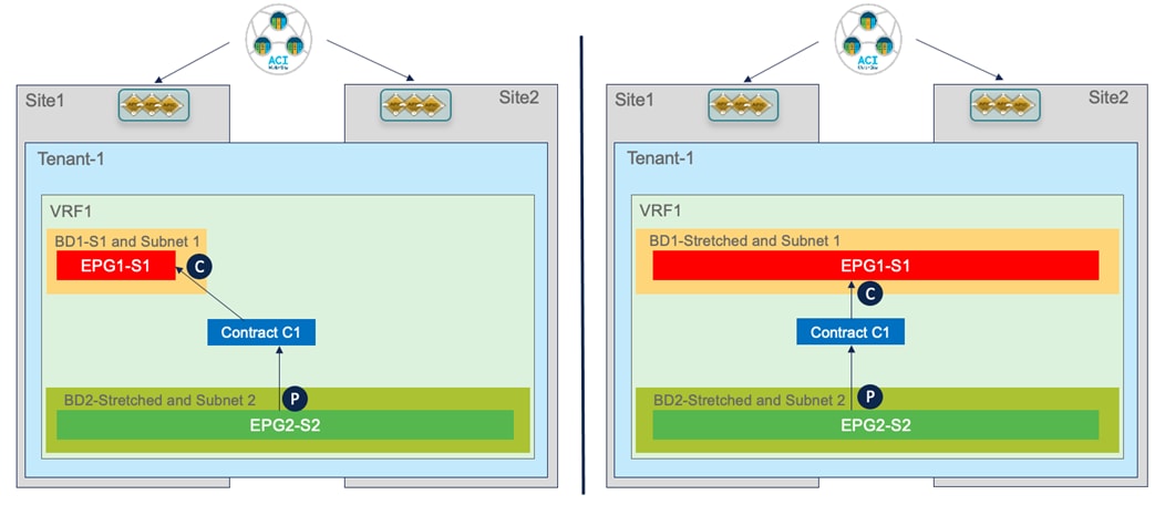
Inter-EPGs Communication Between Local and/or Stretched EPGs
Creating Site Local EPGs/BDs
The creation of site-local EPGs/BDs is similar to what is described in the stretched EPG use case. The main difference is that those objects should be defined in templates that are only associated with the specific ACI fabrics where the policies should be provisioned. Figure 53 displays the creation of EPG1-S1 and BD1-S1 that need to be only provisioned to Site1 (a similar configuration is needed in the template associated with Site2 for the local EPGs/BDs objects).
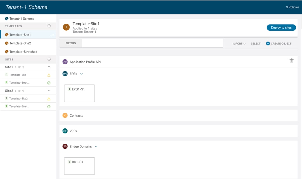
EPGs/BDs Defined in a Site-Specific Template
Notice that inter-template references would hence be needed for example to map local BDs to the previously deployed stretched VRF. Nexus Dashboard Orchestrator allows to cross-reference objects across templates defined in the same schema or even across different schemas.

Local BD and EPG Configuration
After defining the EPG and the BD local objects, it is required to perform the same site-local configuration discussed for the stretched EPG use cases: the BD subnet is assigned at the site-local level (since the BDs are localized) and there is the requirement to map the local EPG to a local domain (Physical, VMM, etc.).
Applying a Security Contract between EPGs
Once the local EPG/BD objects are created in each fabric, to establish communication between them it is required to apply a security policy (contract) allowing all traffic or specific protocols. The contract and the associated filter(s) can be defined in the Template-Stretched, so as to make it available to both fabrics.

Create a Contract in the Template-Stretched
The contract must reference one or more security filters, used to specify what traffic should be allowed. Notice how it is also possible to create a filter with a “Deny” entry (“Permit” was the only option available in older releases).

Define a Deny/Permit Filter Associated to the Contract
The last step consists in creating the specific filter’s entry used to define the traffic flows that should be permitted (or denied). In the specific example in Figure 57 below we simply use the default settings that translate to match all traffic.

Create the Filter’s Entry to Deny/Permit Traffic
Once the contract with the associated filters is ready, it is possible to define the EPG that “provides” the contract and the EPG that “consumes” it. The best practices recommendation when using contracts with ACI Multi-Site is to always clearly identify a provider and a consumer side for all the contracts that are used. This is critical especially when the goal is to attach a Service-Graph to the contract, as discussed in detail in the “Service Node Integration with ACI Multi-Site” section. For more detailed information on the use of ACI contracts, please refer to the document below:
Verifying EPG-to-EPG Intersite Communication
 Once the contract is applied, intersite connectivity between endpoints part of the different EPGs can be established. Before the endpoints start communicating with each other, they are locally learned on the leaf node they connect to, as shown in the outputs below.
Endpoints Connected to Local EPGs
Leaf 101 Site1
Leaf101-Site1# show endpoint vrf Tenant-1:VRF1
Legend:
s - arp H - vtep V - vpc-attached p - peer-aged
R - peer-attached-rl B - bounce S - static M - span
D - bounce-to-proxy O - peer-attached a - local-aged m - svc-mgr
L - local E - shared-service
+--------------------------------+---------------+-----------------+--------------+-------------+
VLAN/ Encap MAC Address MAC Info/ Interface
Domain VLAN IP Address IP Info
+--------------------------------+---------------+-----------------+--------------+-------------+
55 vlan-819 0050.56b9.1bee LpV po1
Tenant-1:VRF1 vlan-819 10.10.1.1 LpV po1
Leaf 303 Site2
Leaf303-Site2# show endpoint vrf Tenant-1:VRF1
Legend:
s - arp H - vtep V - vpc-attached p - peer-aged
R - peer-attached-rl B - bounce S - static M - span
D - bounce-to-proxy O - peer-attached a - local-aged m - svc-mgr
L - local E - shared-service
+--------------------------------+---------------+-----------------+--------------+-------------+
VLAN/ Encap MAC Address MAC Info/ Interface
Domain VLAN IP Address IP Info
+--------------------------------+---------------+-----------------+--------------+-------------+
34 vlan-118 0050.56b3.e41e LV po4
Tenant-1:VRF1 vlan-118 10.10.2.2 LV po4
On the routing table of the leaf node, as a result of the contract, it is also installed the IP subnet associated with the remote EPG pointing to the proxy-TEP address provisioned on the local spine nodes. The reverse happens on the leaf node in Site2.
Leaf 101 Site1
Leaf101-Site1# show ip route vrf Tenant-1:VRF1
IP Route Table for VRF "Tenant-1:VRF1"
'*' denotes best ucast next-hop
'**' denotes best mcast next-hop
'[x/y]' denotes [preference/metric]
'%<string>' in via output denotes VRF <string>
10.10.1.0/24, ubest/mbest: 1/0, attached, direct, pervasive
*via 10.1.112.66%overlay-1, [1/0], 01:01:38, static, tag 4294967294
10.10.1.254/32, ubest/mbest: 1/0, attached, pervasive
*via 10.10.1.254, vlan54, [0/0], 01:01:38, local, local
10.10.2.0/24, ubest/mbest: 1/0, attached, direct, pervasive
*via 10.1.112.66%overlay-1, [1/0], 00:04:51, static, tag 4294967294
Leaf 303 Site2
Leaf303-Site2# show ip route vrf Tenant-1:VRF1
IP Route Table for VRF "Tenant-1:VRF1"
'*' denotes best ucast next-hop
'**' denotes best mcast next-hop
'[x/y]' denotes [preference/metric]
'%<string>' in via output denotes VRF <string>
10.10.1.0/24, ubest/mbest: 1/0, attached, direct, pervasive
*via 10.0.136.66%overlay-1, [1/0], 00:06:47, static, tag 4294967294
10.10.2.0/24, ubest/mbest: 1/0, attached, direct, pervasive
*via 10.0.136.66%overlay-1, [1/0], 00:06:47, static, tag 4294967294
10.10.2.254/32, ubest/mbest: 1/0, attached, pervasive
*via 10.10.2.254, vlan33, [0/0], 00:06:47, local, local
Once connectivity between the endpoints is established, the leaf nodes in each site learn via data-plane activity the specific information for the remote endpoints. The output below shows for example the endpoint table for the leaf node in Site1.
Leaf 101 Site1
Leaf101-Site1# show endpoint vrf Tenant-1:VRF1
Legend:
s - arp H - vtep V - vpc-attached p - peer-aged
R - peer-attached-rl B - bounce S - static M - span
D - bounce-to-proxy O - peer-attached a - local-aged m - svc-mgr
L - local E - shared-service
+--------------------------------+---------------+-----------------+--------------+-------------+
VLAN/ Encap MAC Address MAC Info/ Interface
Domain VLAN IP Address IP Info
+--------------------------------+---------------+-----------------+--------------+-------------+
Tenant-1:VRF1 10.10.2.2 tunnel26
55 vlan-819 0050.56b9.1bee LpV po1
Tenant-1:VRF1 vlan-819 10.10.1.1 LpV po1
The remote endpoint 10.10.2.2 is learned as reachable via the VXLAN tunnel26. As expected, the destination of such a tunnel is the O-UTEP address for Site2 (172.16.200.100).
Leaf 101 Site1
Leaf101-Site1# show interface tunnel 26
Tunnel26 is up
MTU 9000 bytes, BW 0 Kbit
Transport protocol is in VRF "overlay-1"
Tunnel protocol/transport is ivxlan
Tunnel source 10.1.0.68/32 (lo0)
Tunnel destination 172.16.200.100/32
Verifying Namespace Translation Information
As discussed for the stretched EPG use cases, the creation of translation entries in the spines is required every time an intersite communication must be established using the VXLAN data path. In the specific use case of inter-EPG connectivity between EPGs/BDs that are locally deployed in each fabric, the creation of a security policy between them leads to the creation of the so-called ‘shadow objects’ (Figure 59) in the remote site’s APIC domain.
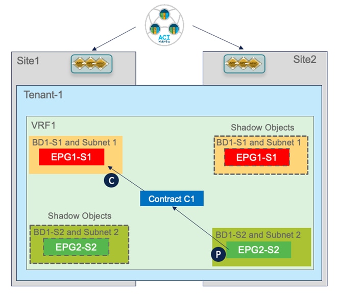
Creation of Shadow Objects
Starting from ACI release 5.0(2), the shadow objects are hidden by default on APIC. To enable their display, it is required to set check the flag for the “Show Hidden Policies” option shown in Figure 60.

Enabling the Display of Shadow Objects
The use of the “Template Deployment Plan” feature, available since Nexus Dashboard Orchestrator release 3.4(1), is quite interesting as it allows to clearly provide the information of what objects are created and where. In our example, when we configure the EPG2-S2 in Site2 to consume the contract provided by EPG1-S1 in Site1 (information provided in the “Deploy to sites” window in Figure 61), the Deployment Plan highlights the creation of those shadow objects in both sites (figure 62).
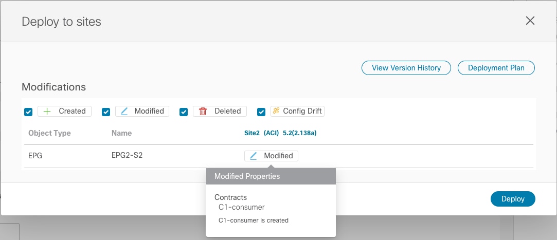
Adding a Consumed Contract to EPG2-S2
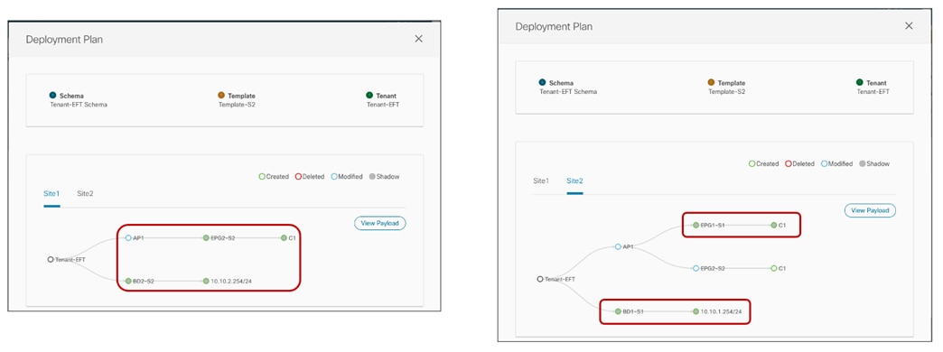
Creation of Shadow Objects Highlighted by the Deployment Plan
The creation of shadow objects is required to be able to assign them the specific resources (Segment IDs, class IDs, etc.) that must be configured in the translation tables of the spines to allow for successful intersite data plane communication.
For example, when looking at the APIC in Site2, we can notice that the EPG and BD locally defined in Site2 are appearing as shadow objects there.

Display of Shadow Objects on APIC
EPG1-S1 and BD1-S1 are objects that were locally created only in Site1 (since they represent site-local objects). However, the establishment of a security policy between EPG1-S1 and EPG2-S2 caused the creation of those objects also on the APIC managing Site2. The same behavior is exhibited for EPG2-S2 and BD2-S2. Figure 64 and Figure 65 display the specific Segment IDs and class IDs values assigned to those objects (the VRF is not shown as the entries are the same previously displayed in Figure 49 and Figure 50).

Segment IDs and Class IDs for Local and Shadow Objects in Site1

Segment IDs and Class IDs for Local and Shadow Objects in Site2
Those values are then programmed in the translation tables of the spines to ensure they can perform the proper translation functions when traffic is exchanged between endpoints in Site1 part of EPG1-S1 and endpoints in Site2 part of EPG2-S2.
For what concerns the Segment IDs, the only translation entry that is required is the one for the VRF. This is because when routing between sites, the VRF L3 VNID value is inserted in the VXLAN header to ensure that the receiving site can then perform the Layer 3 lookup in the right routing domain. There is no need of installing translation entries for the Segment IDs associated with the BDs since there will never be intersite traffic carrying those values in the VXLAN header (given that those BDs are not stretched).
Spine 1101 Site1
Spine1101-Site1# show dcimgr repo vnid-maps
--------------------------------------------------------------
Remote | Local
site Vrf Bd | Vrf Bd Rel-state
--------------------------------------------------------------
2 2359299 | 3112963 [formed]
Spine 401 Site2
Spine401-Site2# show dcimgr repo vnid-maps
--------------------------------------------------------------
Remote | Local
site Vrf Bd | Vrf Bd Rel-state
--------------------------------------------------------------
1 3112963 | 2359299 [formed]
The class IDs for the EPGs and shadow EPGs are instead displayed in the output below.
Spine 1101 Site1
Spine1101-Site1# show dcimgr repo sclass-maps
----------------------------------------------------------
Remote | Local
site Vrf PcTag | Vrf PcTag Rel-state
----------------------------------------------------------
2 2359299 32771 | 3112963 16388 [formed]
2 2359299 16390 | 3112963 32772 [formed]
Spine 401 Site2
Spine401-Site2# show dcimgr repo sclass-maps
----------------------------------------------------------
Remote | Local
site Vrf PcTag | Vrf PcTag Rel-state
----------------------------------------------------------
1 3112963 32772 | 2359299 16390 [formed
1 3112963 16388 | 2359299 32771 [formed]
In addition to the programming of the translation entries on the spine, the assignment of class IDs to the shadow EPGs is also important to be able to properly apply the security policy associated with the contract. As already discussed in the “Verifying EPG-to-EPG Intersite Communication” section, when intra-VRF intersite traffic flows are established, remote endpoint information is learned on the local leaf nodes. This ensures that the contract can always be applied at the ingress leaf node for both directions of the flow.
The output below shows the security rules programmed on leaf 101 in Site1, which is where the endpoint part of EPG1-S1 is locally connected. As you can notice, there is a permit entry associated to the contract C1 for communication between 16388 (the class ID of EPG1-S1) and 32772 (the class ID of the shadow EPG2-S2). There is also an entry for the return flow, which will be used only if for some reason the policy can’t be applied in the ingress direction on the remote leaf node in Site2.
Leaf 101 Site1
Leaf101-Site1# show zoning-rule scope 3112963
+---------+--------+--------+----------+----------------+---------+---------+-------------+----------+----------------------+
| Rule ID | SrcEPG | DstEPG | FilterID | Dir | operSt | Scope | Name | Action | Priority |
+---------+--------+--------+----------+----------------+---------+---------+-------------+----------+----------------------+
| 4151 | 0 | 0 | implicit | uni-dir | enabled | 3112963 | | deny,log | any_any_any(21) |
| 4200 | 0 | 0 | implarp | uni-dir | enabled | 3112963 | | permit | any_any_filter(17) |
| 4198 | 0 | 15 | implicit | uni-dir | enabled | 3112963 | | deny,log | any_vrf_any_deny(22) |
| 4213 | 0 | 32771 | implicit | uni-dir | enabled | 3112963 | | permit | any_dest_any(16) |
| 4219 | 16388 | 32772 | default | uni-dir-ignore | enabled | 3112963 | Tenant-1:C1 | permit | src_dst_any(9) |
| 4220 | 32772 | 16388 | default | bi-dir | enabled | 3112963 | Tenant-1:C1 | permit | src_dst_any(9) |
| 4203 | 0 | 32770 | implicit | uni-dir | enabled | 3112963 | | permit | any_dest_any(16) |
+---------+--------+--------+----------+----------------+---------+---------+-------------+----------+----------------------+
Similar output can be found on leaf 303 in Site2 where the endpoint part of EPG2-S2 is locally connected. Notice how the class IDs values used here are the ones programmed in Site2 for the shadow EPG1-S1 (32771) and local EPG2-S2 (16390).
Leaf 303 Site2
Leaf303-Site2# show zoning-rule scope 2359299
+---------+--------+--------+----------+----------------+---------+---------+-------------+----------+----------------------+
| Rule ID | SrcEPG | DstEPG | FilterID | Dir | operSt | Scope | Name | Action | Priority |
+---------+--------+--------+----------+----------------+---------+---------+-------------+----------+----------------------+
| 4183 | 0 | 0 | implicit | uni-dir | enabled | 2359299 | | deny,log | any_any_any(21) |
| 4182 | 0 | 0 | implarp | uni-dir | enabled | 2359299 | | permit | any_any_filter(17) |
| 4181 | 0 | 15 | implicit | uni-dir | enabled | 2359299 | | deny,log | any_vrf_any_deny(22) |
| 4176 | 0 | 16387 | implicit | uni-dir | enabled | 2359299 | | permit | any_dest_any(16) |
| 4190 | 0 | 16386 | implicit | uni-dir | enabled | 2359299 | | permit | any_dest_any(16) |
| 4205 | 0 | 16389 | implicit | uni-dir | enabled | 2359299 | | permit | any_dest_any(16) |
| 4207 | 16390 | 32771 | default | bi-dir | enabled | 2359299 | Tenant-1:C1 | permit | src_dst_any(9) |
| 4206 | 32771 | 16390 | default | uni-dir-ignore | enabled | 2359299 | Tenant-1:C1 | permit | src_dst_any(9) |
+---------+--------+--------+----------+----------------+---------+---------+-------------+----------+----------------------+
Use of Preferred Group for Enabling Intersite Connectivity
An alternative approach to the use of contracts to allow inter-EPG communication intra-VRF is the use of the Preferred Group functionality.
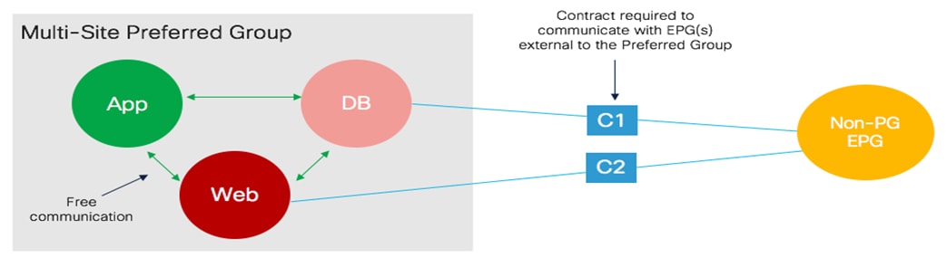
Use of Preferred Group for Free Intra-VRF Communication Between EPGs
For each defined VRF there is support for one Preferred Group and EPGs can be selectively added to it. EPGs that are part of the Preferred Group can communicate with each other without using a contract. Communication with EPGs that are not part of the Preferred Group still mandates the definition of a security policy (Figure 66).
Preferred Group on APIC must be globally enabled (at the VRF level) to ensure the functionality gets activated. As highlighted in Figure 67, by default this knob is disabled.

Global Preferred Group Knob on APIC
When the global knob is disabled, EPGs in the Preferred Group won’t be able to freely communicate with each other. However, the global VRF-level knob is not exposed on Nexus Dashboard Orchestrator and the behavior is the following if adding/removing EPGs to the Preferred Group only on the Nexus Dashboard Orchestrator:
● When adding the first EPG to the Preferred Group on NDO, NDO will also take care of enabling the global knob at the VRF level.
● When removing the last EPG from the Preferred Group on NDO, NDO will also take care of disabling the global knob at the VRF level.
The behavior is a bit different for brownfield scenarios, where Preferred Group is already globally enabled at the APIC level (for example because the Preferred Group functionality is enabled for EPGs deployed directly on APIC before NDO was integrated into the design). Under those conditions, before starting to add EPGs to the Preferred Group on NDO, it is strongly recommended to import the VRF object from APIC into NDO. Doing that provides to NDO the information that preferred group is already enabled (at the APIC level): this ensures that when removing the last EPG from the Preferred Group on NDO, NDO does not disable the global knob to avoid impacting communication between EPGs that may still be part of the Preferred Group and not managed by NDO (i.e. the EPGs that have been configured directly on APIC and not imported into NDO).
The configuration to add an EPG to the Preferred Group on NDO is quite simple and shown in Figure 68; it can be applied to EPGs that are locally defined in a site or stretched across locations.

Adding an EPG to Preferred Group on NDO
Once the configuration is deployed, translation entries and shadow objects will be automatically created to ensure intersite connectivity can be established between all the EPGs that are part of the Preferred Group. Please refer to the ACI scalability guides for more information about the maximum number of EPGs that can be deployed as part of the preferred group in a Multi-Site deployment.
The output below highlights the security rules programmed on the ACI leaf nodes as a result of the enablement.
Leaf 101 Site1
Leaf101-Site1# show zoning-rule scope 3112963
+---------+--------+--------+----------+---------+---------+---------+------+----------+----------------------+
| Rule ID | SrcEPG | DstEPG | FilterID | Dir | operSt | Scope | Name | Action | Priority |
+---------+--------+--------+----------+---------+---------+---------+------+----------+----------------------+
| 4151 | 0 | 0 | implicit | uni-dir | enabled | 3112963 | | deny,log | any_any_any(21) |
| 4200 | 0 | 0 | implarp | uni-dir | enabled | 3112963 | | permit | any_any_filter(17) |
+---------+--------+--------+----------+---------+---------+---------+------+----------+----------------------+
Note: The entries with “0” as SrcEPG and DstEPG are implicit permit rules that are added because of the Preferred Group configuration (implicit deny rules would be added if an EPG that is not in the preferred group is added). For more information on Preferred Group, please refer to the paper below:
Use of vzAny
Another interesting functionality that can be used at the VRF level for EPGs is vzAny. vzAny is a logical grouping construct representing all the EPGs that are deployed inside a given VRF (i.e. the EPGs are mapped to BDs that are part of the VRF). The use of vzAny allows simplifying the application of security policies to implement two specific use cases: the creation of many-to-one connectivity model and creation of any-to-any connectivity model.
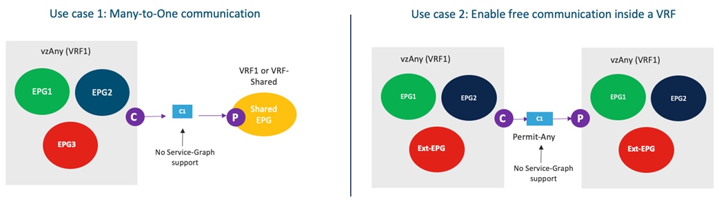
vzAny Use Cases
It is important to highlight a couple of restrictions that apply to the use of vzAny in a Multi-Site deployment:
● As of Nexus Dashboard Orchestrator 3.5(1) release, it is not possible to have vzAny consuming and/or providing a contract with an attached service graph. This requires implementation changes also at the APIC and switching level so will be supported in the future.
● As shown in the figure above, vzAny can be the consumer of a contract for a shared service scenario (i.e., the provider is an EPG in a different VRF). However, vzAny cannot be the provider of a contract if the consumer is in an EPG in a different VRF (this is a restriction that applies also to ACI single fabric designs).
The second use case represents an alternative approach to Preferred Group when the goal is to remove the application of security policies and just use ACI Multi-Site for establishing network connectivity across fabrics. From a provisioning perspective, the required configuration is quite simple and just requires defining a contract with associated a “permit all” filter (as it was shown in previous Figure 56 and Figure 57. Once the contract is created, it is possible to apply it to vzAny at the VRF level, as shown in Figure 70.

Configure vzAny to Provide/Consume a “Permit all” Contract
The result of the configuration shown above is that translation entries and shadow objects are going to be created in both APIC domains to ensure that all intra-VRF communication can happen freely. From a functional point of view, this configuration is analogous to set to “Unenforced” the policy control enforcement preference for the VRF. Notice that this “VRF unenforced” option is not supported with Multi-Site and is not considered a best practice not even with single fabric deployments. The recommendation is hence to use the vzAny configuration hereby described to achieve the same goal.
Note: As of Nexus Dashboard Orchestrator release 3.5(1), the configuration of vzAny is mutually exclusive with the use of the Preferred Group functionality. It is hence important to decide upfront what approach to take, depending on the specific requirements.
Inter-EPGs Connectivity across Sites (Inter-VRF – Shared Services)
“Shared services” represents a specific use case for establishing intersite connectivity between EPGs that are part of different VRFs. Figure 69 already introduced the concept of shared services in the context of vzAny, but the same functionality can be deployed between specific EPGs.
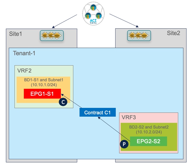
Shared Services Use Case
From a high-level point of view, the considerations are the same already discussed as part of the “Applying a Security Contract between EPGs” for the intra-VRF scenario; to establish connectivity between endpoints part of different EPGs, it is required to create a contract between them. However, few extra considerations become relevant when this connectivity must be created across VRFs, as discussed in the following section.
Provisioning the “Shared Services” configuration
The provisioning of the Shared Services use case highlighted in Figure 71 requires few specific steps.
● Defining a new VRF3 and associate BD2-S2 to that.
● Defining the right scope for the contract: a newly created contract by default has the scope of “VRF”. This means that it will be effective only when applied between EPGs that are part of the same VRF but would not allow communication in the shared services scenario. It is hence required to properly change the scope to “Tenant” or “Global” depending if the VRFs are part of the same tenant or defined across tenants.
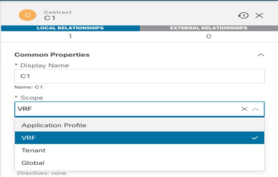
Setting the Proper Scope for the Contract
From a routing perspective, the use of different VRFs ensures logical isolation between separate routing domains. For the shared services use case, it is hence required to populate the proper prefixes information in the different VRFs to be able to establish connectivity across those different routing domains. This functionality is usually referred to as “route-leaking”. The first requisite for enabling the leaking of routes between VRFs is to set the “Shared between VRFs” option for the IP subnets associated with the BDs, as highlighted in Figure 73.

Configuring the BD Subnets for being Leaked between VRFs
In ACI, the leaking of prefixes between VRFs happens in a different way depending on the specific direction that is considered (consumer to provider or provider to consumer).
The IP subnets associated to the BD of the consumer VRF2 (BD1-S1) are leaked into the provider VRF3 based on the configuration of the contract between the EPGs. The leaking in the opposite direction (from the provider VRF3 to the consumer VRF2) is instead the result of a specific configuration applied to the provider EPG2-S2.
As displayed in Figure 74, the same prefix previously configured under BD2-S2 (the BD of the provider EPG) must be configured under the EPG2-S2 itself. The same flags applied to the BD should also be set here, with the addition of the “No Default SVI Gateway” option, which is required as there is no need to install the default gateway as a result of this config that is only needed for leaking the route and for being able to apply the security policy (as it will be clarified in the next section).
Note: The requirement of specifying the subnet’s prefix (or prefixes) under the provider EPG essentially makes it harder to provision route-leaking if multiple EPGs were defined under the same BD (associated to a given IP subnet), as it would require to somehow identify the specific endpoints deployed as part of each EPG, despite being addressed from the same IP subnet range.

Configure the Prefix Under the Provider EPG
Verifying Shared Services Intersite Communication
Figure 75 below shows the scenario that we just provisioned for the shared services use case.
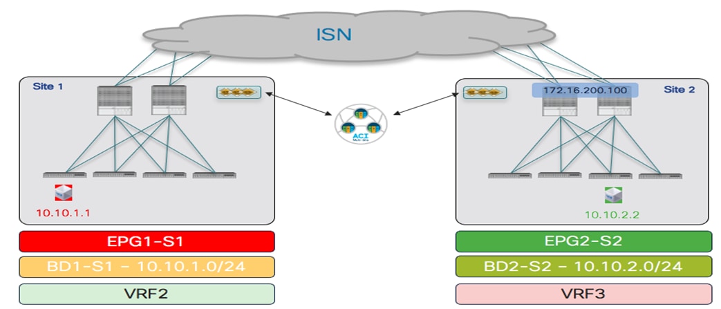
Endpoints Connected to Local EPGs in Separate VRFs (Shared Services Use Case)
The application of a contract between the EPGs locally defined in each site and part of different VRFs has the consequence of generating the creation of shadow objects in the opposite site. In addition to the EPGs and the BDs, also the VRFs are now instantiated as shadow objects.
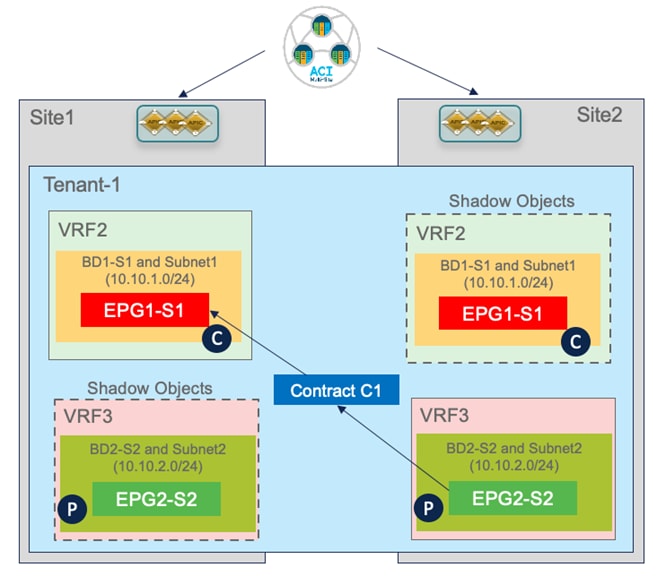
Creation of Shadow Objects for the Shared Services Use Case
This can be verified as usual on APIC and on the spines. Please refer to the previous sections for more information on how to display the shadow objects and retrieve the values configured in the translation tables on the spines. Figure 77 and 78 below highlight the segment IDs and class IDs associated with local and shadow objects in each APIC domain.
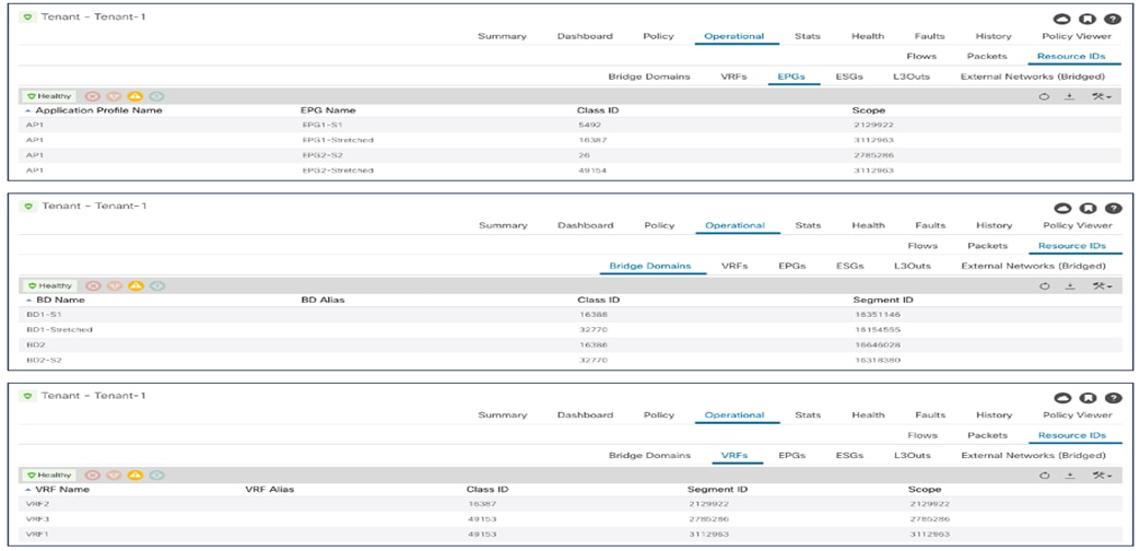
Segment IDs and Class IDs for Local and Shadow Objects in Site1 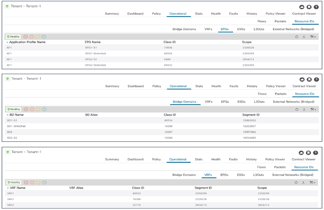
Segment IDs and Class IDs for Local and Shadow Objects in Site2
As a result of the creation of the contract and the IP prefix configuration under the provider EPG, the subnets of BD1-S1 and BD2-S2 are leaked between VRFs, as can be seen in the output below.
Leaf 101 Site1
Leaf101-S1# show ip route vrf Tenant-1:VRF2
IP Route Table for VRF "Tenant-1:VRF2"
'*' denotes best ucast next-hop
'**' denotes best mcast next-hop
'[x/y]' denotes [preference/metric]
'%<string>' in via output denotes VRF <string>
10.10.1.0/24, ubest/mbest: 1/0, attached, direct, pervasive
*via 10.1.112.66%overlay-1, [1/0], 00:08:31, static, tag 4294967294, rwVnid: vxlan-2129922
10.10.1.254/32, ubest/mbest: 1/0, attached, pervasive
*via 10.10.1.254, vlan13, [0/0], 00:08:31, local, local
10.10.2.0/24, ubest/mbest: 1/0, attached, direct, pervasive
*via 10.1.112.66%overlay-1, [1/0], 00:08:31, static, tag 4294967294, rwVnid: vxlan-2785286
Leaf 303 Site2
Leaf303-Site2# show ip route vrf Tenant-1:VRF3
IP Route Table for VRF "Tenant-1:VRF3"
'*' denotes best ucast next-hop
'**' denotes best mcast next-hop
'[x/y]' denotes [preference/metric]
'%<string>' in via output denotes VRF <string>
10.10.1.0/24, ubest/mbest: 1/0, attached, direct, pervasive
*via 10.0.136.66%overlay-1, [1/0], 00:35:33, static, tag 4294967294, rwVnid: vxlan-2326528
10.10.2.0/24, ubest/mbest: 1/0, attached, direct, pervasive
*via 10.0.136.66%overlay-1, [1/0], 00:35:33, static, tag 4294967294, rwVnid: vxlan-2654213
10.10.2.254/32, ubest/mbest: 1/0, attached, pervasive
*via 10.10.2.254, vlan49, [0/0], 00:35:33, local, local
The output above highlights how each of the leaked routes contains the specific information of the Segment ID to be used when encapsulating traffic toward the destination. In Site1, vxlan-2785286 represents the segment ID assigned to the local shadow VRF3 instance. Similarly, vxlan-2326528 in Site2 represents the segment ID assigned to the local shadow VRF2 instance. Encapsulating traffic on the ingress leaf with the Segment ID of the VRF where the remote destination is connected ensures that the receiving leaf in the remote site can properly perform the lookup in the right routing domain.
Different from the intra-VRF use case, where the security policy is always enforced on the ingress leaf node at a steady state, in the shared services scenario the security policy should always be enforced on the consumer leaf nodes. This is done to avoid scalability issues for the TCAM programming on the provider leaf assuming that many consumer EPGs try to access a common shared resource.
To ensure this is the case, two things are happening:
● Data-plane learning of endpoint information is not happening, to avoid learning the class ID information that would cause the application of the policy on the provider leaf.
● The class ID of the provider EPG is statically programmed on all the consumer leaf nodes as the result of the IP prefix configuration under the provider EPG previously discussed. For the specific scenario displayed in Figure 75, it is possible to verify with the command below that the class ID for the 10.10.2.0/24 subnet is configured on the consumer leaf in Site1:
Leaf 101 Site1
Leaf101-Site1# moquery -d sys/ipv4/inst/dom-Tenant-1:VRF2/rt-[10.10.2.0/24]
Total Objects shown: 1
# ipv4.Route
prefix : 10.10.2.0/24
childAction :
ctrl : pervasive
descr :
dn : sys/ipv4/inst/dom-Tenant-1:VRF2/rt-[10.10.2.0/24]
flushCount : 1
lcOwn : local
modTs : 2020-11-13T22:14:20.696+00:00
monPolDn :
name :
nameAlias :
pcTag : 26
pref : 1
rn : rt-[10.10.2.0/24]
sharedConsCount : 0
status :
tag : 4294967294
trackId : 0
Note: As displayed in previous Figure 77, pcTag 26 represents the class ID for shadow EPG2-S2 installed in the APIC controller for Site1.
As a result, the following security rule is installed on the consumer leaf in Site1 to ensure the policy can be applied:
Leaf 101 Site1
Leaf101-Site1# show zoning-rule scope 2129922
+---------+--------+--------+----------+----------------+---------+---------+-------------+----------+------------------------+
| Rule ID | SrcEPG | DstEPG | FilterID | Dir | operSt | Scope | Name | Action | Priority |
+---------+--------+--------+----------+----------------+---------+---------+-------------+----------+------------------------+
| 4223 | 0 | 0 | implicit | uni-dir | enabled | 2129922 | | deny,log | any_any_any(21) |
| 4224 | 0 | 0 | implarp | uni-dir | enabled | 2129922 | | permit | any_any_filter(17) |
| 4225 | 0 | 15 | implicit | uni-dir | enabled | 2129922 | | deny,log | any_vrf_any_deny(22) |
| 4228 | 0 | 16388 | implicit | uni-dir | enabled | 2129922 | | permit | any_dest_any(16) |
| 4227 | 26 | 16397 | default | uni-dir-ignore | enabled | 2129922 | Tenant-1:C1 | permit | src_dst_any(9) |
| 4226 | 26 | 0 | implicit | uni-dir | enabled | 2129922 | | deny,log | shsrc_any_any_deny(12) |
| 4213 | 16397 | 26 | default | bi-dir | enabled | 2129922 | Tenant-1:C1 | permit | src_dst_any(9) |
+---------+--------+--------+----------+----------------+---------+---------+-------------+----------+------------------------+
Notice how the Provider EPG is getting a special class ID for the shared services use case (26, in this specific example for Site1). This value is taken from a pool that has global uniqueness across all the deployed VRFs. This is different for the intra-VRF use case, where the class IDs assigned are locally significant for each VRF.
Finally, the same considerations (and provisioning steps) described above can also be applied when the goal is establishing communication between VRFs that are part of different tenants (Figure 79).
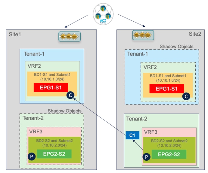
Inter-Tenant Shared Services Use Case
The only specific considerations that apply to this deployment model are the following:
● The contract must be provisioned with scope “Global” and defined in the provider tenant (Tenant-2 in the example above).
● The creation of the contract between EPGs that are part of separate VRFs and tenants would cause also the instantiation of “shadow tenants” in the scenarios where the tenants are only locally deployed in each site.
Finally, the contract defined in the provider tenant must be exported to the consumer tenant as a “contract interface”. However, this is automatically done by the Orchestrator Service when the contract is applied between EPGs that are part of different tenants (which is why the provisioning, from the Orchestrator perspective, is identical to the use case shown in Figure 76).
Connectivity to the External Layer 3 Domain
The use cases discussed in the previous sections dealt with the establishment of Layer 2 and Layer 3 connectivity between ACI sites part of the same Multi-Site domain, usually referred to as “east-west” connectivity. In this section, we are going instead to describe multiple use cases providing access to the DC resources from the external Layer 3 network domain, generically defined as “north-south” connectivity.
Use Case 1: Site-Local L3Out Connections to Communication with External Resources (Intra-VRF)
This first use case, shown in Figure 80, covers access to a common set of external resources from local L3Out connections deployed in each site.
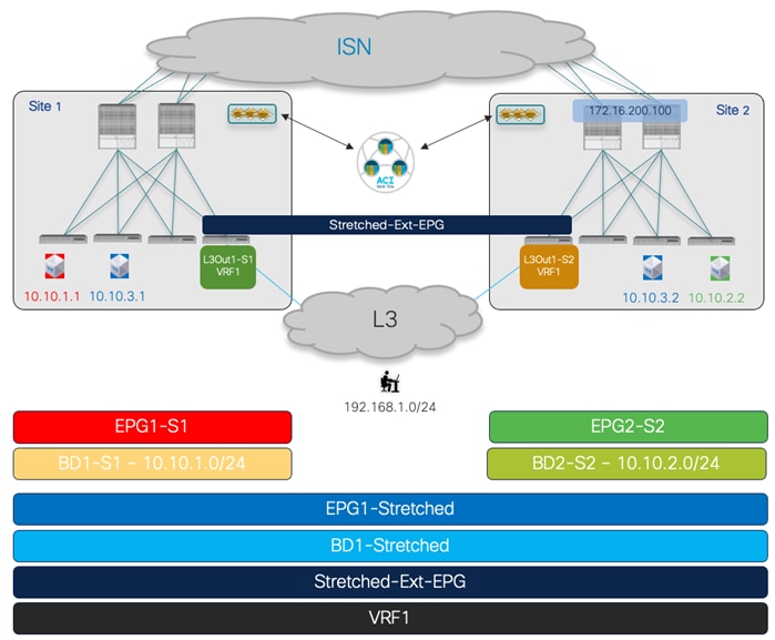
Site Local L3Outs Providing Access to a Common Set of External Resources
The EPGs and BDs (a mix of site-local and stretched objects), all part of the same VRF1 routing domain, have already been provisioned for the use cases previously described. The first required configuration step consists hence in creating the L3Outs in each local site. Figure 81 shows how to do that on Nexus Dashboard Orchestrator for L3Out1-S1 defined in fabric 1. The same can be done to define L3Out1-S2 in the template associated with Site2. It is a best practice recommendation to define L3Outs with unique names in each site, as it provides more flexibility for the provisioning of many use cases (as it will be clarified in the following sections).
Note: The diagram shown in Figure 80 is using a single BL node in each fabric and it is hence not representative of a real production environment that normally leverages at least a pair of BL nodes for the sake of redundancy.
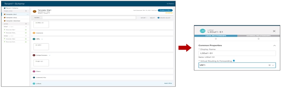
Create a Local L3Out in Site1
Notice that in the current Nexus Dashboard Orchestrator 3.5(1) release it is only possible to create the L3Out object from NDO, whereas the configuration of logical nodes, logical interfaces, routing protocol, etc. is still handled at the specific APIC domain level. Describing in detail how to create an L3Out on APIC is out of the scope of this paper, for more information please refer to the paper below:
Once the L3Outs in each site are provisioned, we can proceed with the creation of the External EPG associated with the L3Out. As a best practice recommendation, a single External EPG should be deployed when the L3Out connections provide access to a common set of external resources. The use of a ‘stretched’ External EPG, shown in Figure 82 below, simplifies the definition of the security policy required for establishing north-south connectivity.
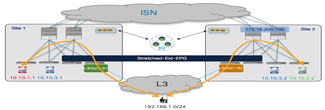
Use of a ‘Stretched’ External EPG
Since the same External EPG must be deployed in both fabrics, its configuration should be done as part of the Template-Stretched that is associated with both sites.

Creation of a ‘Stretched’ External EPG
The External EPG should then have one or more IP prefixes defined for being able to classify external resources as part of the EPG (to be able to apply security policies with internal EPGs). The example, in Figure 84 it is displayed a common approach consisting of the use of a ‘catch-all’ 0.0.0.0/0 prefix to ensure that all the external resources can be classified as part of this specific External EPG.

Define a ‘Catch-all’ Classification Subnet
Once the External EPG has been defined, it is then required to map it at the site level to the local L3Out objects previously defined for each fabric. Figure 85 shows the association of the Ext-EPG to the L3Out defined in Site1, a similar mapping is required for the L3Out in Site2.

Mapping the External EPG to the Local L3Out Connection
Note: The NDO GUI gives also the capability of mapping an External EPG to the L3Out at the global template level. However, in the scenario discussed in this use case where separate L3Out connections are created in each fabric, it is mandatory to create the mapping at the site level.
Once the External EPG has been provisioned and mapped to the local L3Outs, two final steps are required to establish the N-S connectivity shown in Figure 82:
● Establish a security policy between the internal EPGs and the External EPG: we can use the same contract C1 previously used for intra-VRF EPG-to-EPG connectivity. For what concerns the contract’s direction, it is irrelevant if the Ext-EPG is providing the contract and the internal EPGs are consuming it or vice versa.
Alternatively, it is possible to use the Preferred Group or vzAny functionality to allow free north-south connectivity, in place of applying the contract. A specific consideration applies when using Preferred Group for the Ext-EPG: 0.0.0.0/0 is not supported in that case for classifying all the traffic originated from external sources. The recommended configuration to cover the same address space consists in splitting the range into two separate parts, as shown in Figure 86.
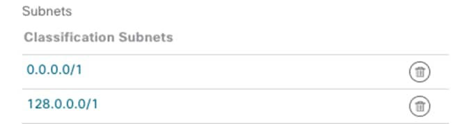
Classification Subnet when Adding the External EPG to the Preferred Group
● Announce the internal BD subnets toward the external network domain: for achieving this, first it is required to set the “Advertised Externally” flag for the IP subnet(s) associated with the BDs, as shown in Figure 87 below.

Set the “Advertised Externally” flag to announce the BD subnet toward the external network
As a second step, it is required to specify out of which L3Out the BD subnet prefixes should be advertised. This is typically achieved on Nexus Dashboard Orchestrator by associating the L3Out to the BD at the site level. Figure 88 shows the configuration required for BD1-S1 that is locally deployed in Site1. For BDs that are stretched across sites, the BD should be instead mapped in each site to the locally defined L3Out.
![]()
![]()
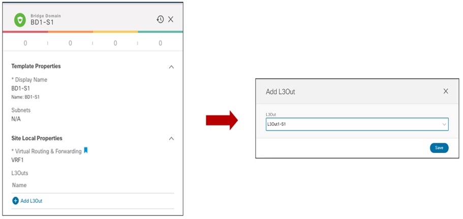
Mapping the L3Out to the BD
Note: The use of unique name L3Out connections in each site is quite important to have tight control on where to announce the BD’s subnets based on the mapping performed in the figure above.
Use Case 1 Verification
Once the configuration previously described is fully provisioned, north-south connectivity can be successfully established. Even when the internal EPGs establish a security contract with a stretched external EPG (as shown in previous Figure 82), for the intra-VRF scenario hereby discussed the prefixes information for IP subnets that are locally defined in each site will be only sent out the local L3Out connections. This ensures that inbound traffic will always be steered toward the fabric where that subnet is locally defined. For BDs that are stretched, the stretched IP subnet will instead be advertised by default out of the L3Outs defined in both sites, which essentially means that inbound traffic could be received in the ‘wrong’ site and will then need to be re-routed across the ISN (Figure 89).
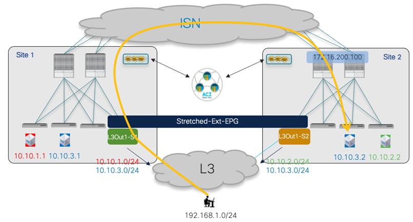
Suboptimal Inbound Traffic Path
The inbound traffic flows destined to endpoints belonging to the stretched EPG/BD can be optimized by configuring the host-based routing functionality, which allows to advertise out of each L3Out the specific /32 prefixes for the endpoints discovered in the local site.
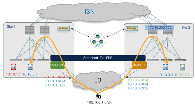
Host-based Routing Advertisement for Inbound Traffic Optimization
The advertisement of host-based routing information can be enabled on NDO for each BD and should be done only for the BDs that are stretched across sites. As highlighted in Figure 91, the “Host Route” flag is enabled for BD1-Stretched and this is done at the site level.
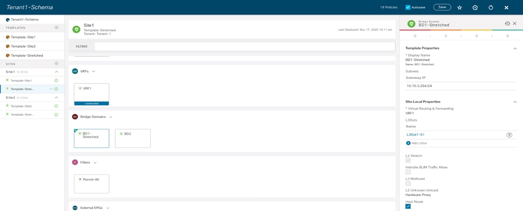
Enabling Host-based Routing on NDO
For what concerns the outbound traffic flows, from the point of view of the compute leaf nodes in each fabric the only path toward the external IP prefix 192.168.1.0/24 is always and only via the local Border Leaf (BL) node. This is because external prefixes learned on an L3Out connection in Site 1 are not advertised by default to Site 2 (and vice versa) using the MP-BGP control plane between spine nodes, unless the intersite L3Out functionality is enabled (this will be discussed in more detail in the “Deploying Intersite L3Out” section).
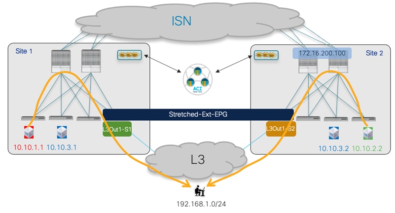
Outbound Communication always using the local L3Out
In the output below, 10.1.0.69 represents the TEP address of the Border Leaf node in site 1, whereas 10.0.224.96 is the TEP address of the Border Leaf node in Site2.
Leaf 101 Site1
Leaf101-Site1# show ip route vrf Tenant-1:VRF1
IP Route Table for VRF "Tenant-1:VRF1"
'*' denotes best ucast next-hop
'**' denotes best mcast next-hop
'[x/y]' denotes [preference/metric]
'%<string>' in via output denotes VRF <string>
10.10.1.0/24, ubest/mbest: 1/0, attached, direct, pervasive
*via 10.1.112.66%overlay-1, [1/0], 00:47:34, static
10.10.1.254/32, ubest/mbest: 1/0, attached, pervasive
*via 10.10.1.254, vlan43, [0/0], 03:04:11, local, local
10.10.2.0/24, ubest/mbest: 1/0, attached, direct, pervasive
*via 10.1.112.66%overlay-1, [1/0], 00:46:04, static
10.10.3.0/24, ubest/mbest: 1/0, attached, direct, pervasive
*via 10.1.112.66%overlay-1, [1/0], 00:47:38, static
10.10.3.254/32, ubest/mbest: 1/0, attached, pervasive
*via 10.10.3.254, vlan64, [0/0], 4d08h, local, local
192.168.1.0/24, ubest/mbest: 1/0
*via 10.1.0.69%overlay-1, [200/0], 03:02:43, bgp-65501, internal, tag 3
Leaf 303 Site2
Leaf303-Site2# show ip route vrf Tenant-1:VRF1
IP Route Table for VRF "Tenant-1:VRF1"
'*' denotes best ucast next-hop
'**' denotes best mcast next-hop
'[x/y]' denotes [preference/metric]
'%<string>' in via output denotes VRF <string>
10.10.2.0/24, ubest/mbest: 1/0, attached, direct, pervasive
*via 10.0.136.66%overlay-1, [1/0], 02:03:12, static
10.10.2.254/32, ubest/mbest: 1/0, attached, pervasive
*via 10.10.2.254, vlan16, [0/0], 04:21:10, local, local
10.10.3.0/24, ubest/mbest: 1/0, attached, direct, pervasive
*via 10.0.136.66%overlay-1, [1/0], 02:04:45, static
10.10.3.254/32, ubest/mbest: 1/0, attached, pervasive
*via 10.10.3.254, vlan25, [0/0], 5d09h, local, local
192.168.1.0/24, ubest/mbest: 1/0
*via 10.0.224.96%overlay-1, [200/0], 00:19:39, bgp-100, internal, tag 30
From a security policy point of view (unless Preferred Group is used), for intra-VRF north-south traffic flows the contract is always and only applied on the compute leaf node (and never on the border leaf nodes). This is true independently from the direction of the contract (i.e. who is the provider and who is the consumer), but under the assumption that the VRF’s “Policy Control Enforcement Direction” is always kept to the default “Ingress” value.

Default VRF’s Settings
Note: It is strongly recommended to keep this setting to its default value, as it is required for being able to apply Service Graph and PBR to north-south traffic flows. For more information, please refer to the “Service Node Integration with ACI Multi-Site” section.
The output below shows the zoning-rule configuration on the Border Leaf node for Site1. 16388 represents the class ID for the internal EPG1-S1, whereas 49153 is the Class ID for VRF1. When traffic is received on an L3Out with the External EPG configured with the 0.0.0.0/0 prefix for classification, it is assigned the class ID of the VRF (of the L3Out) instead of the specific class ID of the External EPG (you need to use a more specific classification subnet for that, as shown later in this section). By looking at the last entry in the table below (rule ID 4225), you would hence conclude that the security policy for inbound traffic can be applied on the border leaf node 104.
Leaf 104 Site1
Leaf104-Site1# show zoning-rule scope 3112963
+---------+--------+--------+----------+---------+---------+---------+-------------+----------+----------------------+
| Rule ID | SrcEPG | DstEPG | FilterID | Dir | operSt | Scope | Name | Action | Priority |
+---------+--------+--------+----------+---------+---------+---------+-------------+----------+----------------------+
| 4148 | 0 | 0 | implicit | uni-dir | enabled | 3112963 | | deny,log | any_any_any(21) |
| 4153 | 0 | 0 | implarp | uni-dir | enabled | 3112963 | | permit | any_any_filter(17) |
| 4199 | 0 | 15 | implicit | uni-dir | enabled | 3112963 | | deny,log | any_vrf_any_deny(22) |
| 4156 | 0 | 16386 | implicit | uni-dir | enabled | 3112963 | | permit | any_dest_any(16) |
| 4206 | 0 | 32770 | implicit | uni-dir | enabled | 3112963 | | permit | any_dest_any(16) |
| 4216 | 0 | 32771 | implicit | uni-dir | enabled | 3112963 | | permit | any_dest_any(16) |
| 4213 | 16387 | 15 | default | uni-dir | enabled | 3112963 | Tenant-1:C1 | permit | src_dst_any(9) |
| 4218 | 49153 | 16387 | default | uni-dir | enabled | 3112963 | Tenant-1:C1 | permit | src_dst_any(9) |
| 4145 | 16388 | 15 | default | uni-dir | enabled | 3112963 | Tenant-1:C1 | permit | src_dst_any(9) |
| 4225 | 49153 | 16388 | default | uni-dir | enabled | 3112963 | Tenant-1:C1 | permit | src_dst_any(9) |
+---------+--------+--------+----------+---------+---------+---------+-------------+----------+----------------------+
This is not the case instead, because leaf 104 does not know how to determine the class ID for the destination of the externally originated traffic flow (10.10.1.1 in our example, which represents the internal endpoint part of EPG1-S1). This is because the internal endpoint information is not learned on the BL node as a result of the north-south communication. Additionally, the specific IP subnet associated with EPG1-S1 (10.10.1.0/24) is also locally installed without any specific class ID information (see the “any” value in the “pcTag” row).
Leaf 104 Site1
Leaf104-Site1# moquery -d sys/ipv4/inst/dom-Tenant-1:VRF1/rt-[10.10.1.0/24]
Total Objects shown: 1
# ipv4.Route
prefix : 10.10.1.0/24
childAction :
ctrl : pervasive
descr :
dn : sys/ipv4/inst/dom-Tenant-1:VRF1/rt-[10.10.1.0/24]
flushCount : 0
lcOwn : local
modTs : 2020-11-16T20:24:29.023+00:00
monPolDn :
name :
nameAlias :
pcTag : any
pref : 1
rn : rt-[10.10.1.0/24]
sharedConsCount : 0
status :
tag : 0
trackId : 0
The output below shows instead the zoning-rule entries on the compute leaf where the internal endpoint 10.10.1.1 is connected that allow to apply the security policy for inbound and outbound flows with the external client 192.168.1.1.
Leaf 101 Site1
Leaf101-Site1# show zoning-rule scope 3112963
+---------+--------+--------+----------+---------+---------+---------+-------------+----------+----------------------+
| Rule ID | SrcEPG | DstEPG | FilterID | Dir | operSt | Scope | Name | Action | Priority |
+---------+--------+--------+----------+---------+---------+---------+-------------+----------+----------------------+
| 4151 | 0 | 0 | implicit | uni-dir | enabled | 3112963 | | deny,log | any_any_any(21) |
| 4200 | 0 | 0 | implarp | uni-dir | enabled | 3112963 | | permit | any_any_filter(17) |
| 4198 | 0 | 15 | implicit | uni-dir | enabled | 3112963 | | deny,log | any_vrf_any_deny(22) |
| 4203 | 0 | 32770 | implicit | uni-dir | enabled | 3112963 | | permit | any_dest_any(16) |
| 4228 | 0 | 32771 | implicit | uni-dir | enabled | 3112963 | | permit | any_dest_any(16) |
| 4210 | 16387 | 15 | default | uni-dir | enabled | 3112963 | Tenant-1:C1 | permit | src_dst_any(9) |
| 4199 | 49153 | 16387 | default | uni-dir | enabled | 3112963 | Tenant-1:C1 | permit | src_dst_any(9) |
| 4224 | 16388 | 15 | default | uni-dir | enabled | 3112963 | Tenant-1:C1 | permit | src_dst_any(9) |
| 4223 | 49153 | 16388 | default | uni-dir | enabled | 3112963 | Tenant-1:C1 | permit | src_dst_any(9) |
+---------+--------+--------+----------+---------+---------+---------+-------------+----------+----------------------+
For inbound flows, the packet carries the VRF class ID in the VXLAN header (49153), so rule 4223 above allows to apply the policy for packets destined to the locally connected endpoint part of EPG1-S1 (identified by Class ID 16388). For outbound flows, entry 4224 is applied, as all the external destinations that are reachable via an External EPG using 0.0.0.0/0 for classification are identified with the specific Class ID value of 15. Notice that the same entry is also available on the Border Leaf node, but it does not have any effect for outbound flows since the compute node set a specific bit in the VXLAN header of the packets sent toward the Border Leaf node to communicate the fact that the policy has already been applied.
If the 0.0.0.0/0 classification subnet in the External EPG was instead replaced by a more specific entry (for example 192.168.1.0/24 to match the subnet of the external clients in our specific example), the zoning-rule table in the compute leaf node would change as shown in the output below. The specific rule IDs 4194 and 4219 allow in this case to apply the security policy for respectively inbound and outbound communication between EPG1-S1 (Class ID 16388) and the External EPG (Class ID 32773).
Leaf 101 Site1
Leaf101-Site1# show zoning-rule scope 3112963
+---------+--------+--------+----------+----------------+---------+---------+-------------+----------+----------------------+
| Rule ID | SrcEPG | DstEPG | FilterID | Dir | operSt | Scope | Name | Action | Priority |
+---------+--------+--------+----------+----------------+---------+---------+-------------+----------+----------------------+
| 4151 | 0 | 0 | implicit | uni-dir | enabled | 3112963 | | deny,log | any_any_any(21) |
| 4200 | 0 | 0 | implarp | uni-dir | enabled | 3112963 | | permit | any_any_filter(17) |
| 4198 | 0 | 15 | implicit | uni-dir | enabled | 3112963 | | deny,log | any_vrf_any_deny(22) |
| 4203 | 0 | 32770 | implicit | uni-dir | enabled | 3112963 | | permit | any_dest_any(16) |
| 4228 | 0 | 32771 | implicit | uni-dir | enabled | 3112963 | | permit | any_dest_any(16) |
| 4219 | 16388 | 32773 | default | uni-dir-ignore | enabled | 3112963 | Tenant-1:C1 | permit | src_dst_any(9) |
| 4194 | 32773 | 16388 | default | bi-dir | enabled | 3112963 | Tenant-1:C1 | permit | src_dst_any(9) |
| 4225 | 16387 | 32773 | default | uni-dir-ignore | enabled | 3112963 | Tenant-1:C1 | permit | src_dst_any(9) |
| 4217 | 32773 | 16387 | default | bi-dir | enabled | 3112963 | Tenant-1:C1 | permit | src_dst_any(9) |
+---------+--------+--------+----------+----------------+---------+---------+-------------+----------+----------------------+
The second use case to consider is the one where the L3Out connections are part of a different VRF than the internal EPGs/BDs, a scenario usually referred to as “shared services”. In this use case, the L3Out VRF (VRF-Shared) is defined in the same tenant where the internal EPGs/BDs belong.
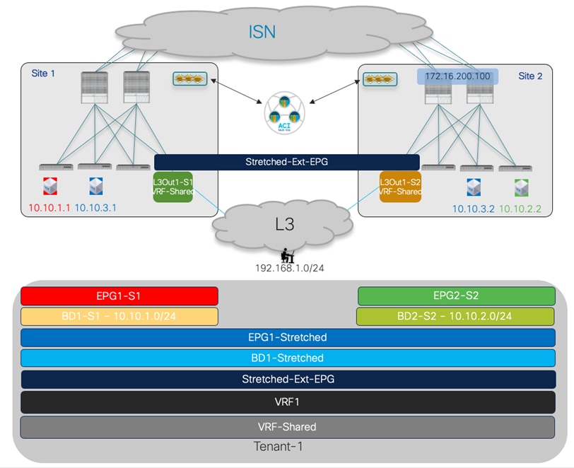
Inter-VRF North-south Connectivity
The only different provisioning steps from the intra-VRF use case previously discussed are the following:
● Configure a contract with the scope “Tenant”.
● Apply the contract between an internal EPG and the External EPG: differently from the intra-VRF use case 1, the leaf node where the security policy is applied depends on the specific provider and consumer side, as it will be clarified in the “Use Case 2 Verification” section.
● Configure the internal BD subnet to ensure it can be advertised outside of the local L3Out. For this to happen across VRFs, there is no need to map the BD to the L3Out (as done in the intra-VRF use case) but it is simply required to select the “Shared between VRFs” flag in addition to the “Advertised Externally” one, as shown in Figure 95.

Setting to Leak a BD’s Subnet into a different VRF
● If the internal EPG is the provider of the contract, the same subnet associated to the BD must also be defined under the EPG itself.
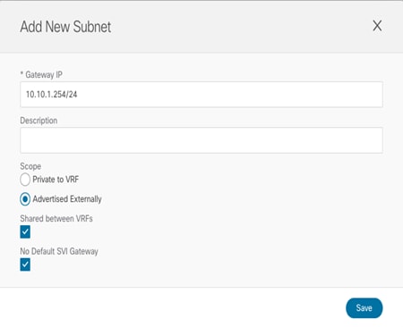
Setting of the Subnet under the Provider EPG
Notice how the same flags already used for the BD must also be set for the EPG’s subnet (Nexus Dashboard Orchestrator would prevent the deployment of the template if that is not the case). Since the configuration above is solely needed for enabling the leaking of the routes between VRFs, the “No Default SVI Gateway” flag should additionally be configured (since the default gateway is already instantiated as the result of the specific BD’s configuration).
● Properly configure the subnets associated with the External EPG to ensure inter-VRF N-S connectivity can be established. This requires performing the setting shown in Figure 97.

Required Setting of the External EPG for inter-VRF North-south Connectivity
In the example above, 0.0.0.0/0 is defined under the Ext-EPG, so the different flags set in the figure cause the following behavior:
● “External Subnets for External EPG”: map to this external EPG (i.e. associate the corresponding class ID) all the incoming traffic (whatever is its source IP address). As previously mentioned, in the specific case of 0.0.0.0/0, the class ID associated with all incoming traffic is in reality the VRF class ID (and not the External EPG class ID).
● “Shared Route Control” with “Aggregate Shared Routes”: allows to leak into the internal VRF all the prefixes that are learned from the external routers (or locally configured as static routes). Without the “Aggregate Shared Routes” flag set, only the 0.0.0.0/0 route would be leaked, if and only if it was received from the external router. The same considerations would apply when configuring a prefix different than 0.0.0.0/0.
“Shared Security Import”: this is required to ensure that the prefix 0.0.0.0/0 (catch-all) is installed on the compute leaf nodes where the internal VRF is deployed with the associated class ID. This allows the compute leaf to properly apply the security policy for flows originated by locally connected endpoints and destined to the external network domain.
Note: When specifying a more specific IP subnet ( for example 192.168.1.0/24), the use of the “Aggregate Shared Routes” is required to leak more specific prefixes part of the /24 subnets that may be learned on the L3Out. Without the flag set, only the /24 prefix would be leaked if received from the external routers.
One important consideration for the inter-VRF use case is related to how the External EPG(s) associated to the L3Out is (are) deployed. As previously mentioned, in this use case the subnet of a BD is advertised toward the external network domain based on the specific use of the flags discussed above, and there is not a need to explicitly map the BD to the L3Out. This means that when deploying a stretched External EPG (as previously shown in Figure 82), you now don’t have the capability of controlling out of which L3Out a BD’s subnet will be announced and by default the IP subnets that only exist in a site will be advertised also out of the L3Out of the remote site (Figure 98).
Advertising BD Subnets in the Shared Services Use Case
In the scenario above, it is possible to change the default behavior and ensure that the routing information advertised out of the local L3Out becomes preferable for locally defined subnets (while enabling host-based routing is still possible for the stretched subnets). Most commonly EBGP adjacencies are established with the external routers, so a simple way to achieve this is, for example, using the AS-Path prepend functionality.
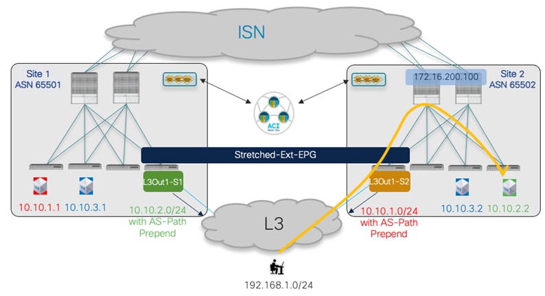
Optimizing Inbound Traffic with the Use of AS-Path Prepend
Figure 100, Figure 101, and Figure 102 highlight the steps needed for this configuration. Notice that the creation and application of a routemap to the L3Out is currently supported only on APIC and not on Nexus Dashboard Orchestrator.
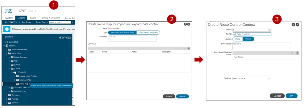
Creation of a “default-export” route-map associated to the L3Out
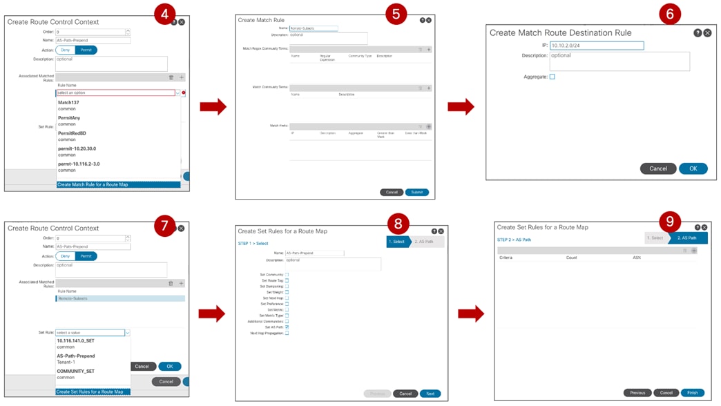
Route Control Context Configuration (Match and Set Prefixes)
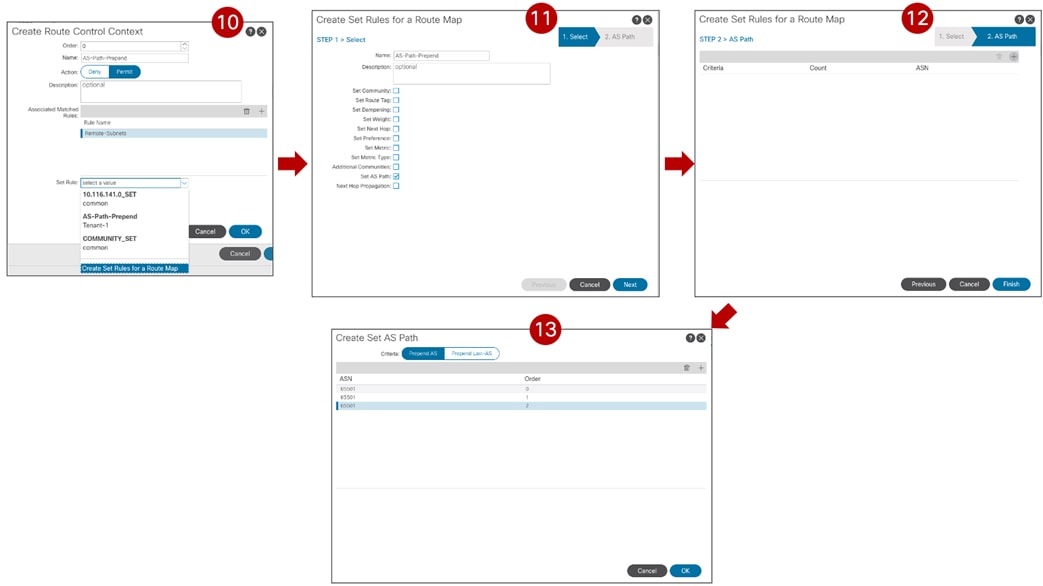
Completion of Route Control Context Set Prefix
Note: Enabling host-based routing for not stretched subnets is an alternative approach to optimize inbound traffic path, assuming there are not scalability concerns.
Use Case 2 Verification
The same considerations made in Figure 89, Figure 90, and Figure 91 for connectivity between internal EPGs/BDs and the external network domain continue to apply also in this use case. This means that optimal inbound routing can be influenced by enabling the host-based routing functionality at the specific BD level, whereas outbound communication always flows via the local L3Out connection.
Figure 100 shows the deployment of VRFs required for the specific north-south inter-VRF use case. As noticed, both VRFs are deployed on the BL node, whereas only the internal VRF is usually present on the compute leaf node.
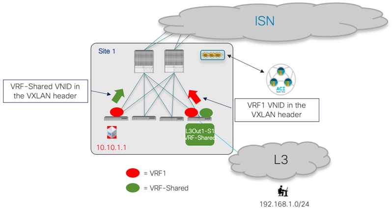
VRFs Deployment and VNIDs in VXLAN Encapsulated Traffic
Additionally, outbound traffic VXLAN encapsulated on the compute leaf uses the VRF-Shared VNID in the header, so that the BL node receiving the traffic will be able to perform the L3 lookup in the VRF-Shared domain before sending the traffic to the external domain. The outputs below show the content of the routing tables on the compute leaf node and on the BL node. On the compute leaf 101, the external prefix 192.168.1.0/24 is leaked into the VRF1 routing table, with the information of rewriting the VNID in the VXLAN header to 2293765 (representing the VNID for VRF-Shared in Site1). On the BL node 104, the internal subnet 10.10.1.0/24 is instead leaked into the VRF-Shared routing table, with the information of rewriting the VNID in the VXLAN header to 3112963 (representing the VNID for VRF1 in Site1).
Leaf 101 Site1
Leaf101-Site1# show ip route vrf Tenant-1:VRF1
IP Route Table for VRF "Tenant-1:VRF1"
'*' denotes best ucast next-hop
'**' denotes best mcast next-hop
'[x/y]' denotes [preference/metric]
'%<string>' in via output denotes VRF <string>
10.10.1.0/24, ubest/mbest: 1/0, attached, direct, pervasive
*via 10.1.112.66%overlay-1, [1/0], 00:21:25, static, rwVnid: vxlan-3112963
10.10.1.254/32, ubest/mbest: 1/0, attached, pervasive
*via 10.10.1.254, vlan43, [0/0], 3d16h, local, local
192.168.1.0/24, ubest/mbest: 1/0
*via 10.1.0.69%overlay-1, [200/0], 00:27:33, bgp-65501, internal, tag 3, rwVnid: vxlan-2293765
Leaf 104 Site1
Leaf104-Site1# show ip route vrf Tenant-1:VRF-Shared
IP Route Table for VRF "Tenant-1:VRF-Shared"
'*' denotes best ucast next-hop
'**' denotes best mcast next-hop
'[x/y]' denotes [preference/metric]
'%<string>' in via output denotes VRF <string>
10.10.1.0/24, ubest/mbest: 1/0, attached, direct, pervasive
*via 10.1.112.66%overlay-1, [1/0], 00:23:32, static, tag 4294967292, rwVnid: vxlan-3112963
192.168.1.0/24, ubest/mbest: 1/0
*via 172.16.1.1%Tenant-1:VRF-Shared, [20/0], 1d20h, bgp-65501, external, tag 3
In the inter-VRF scenario, the leaf nodes where the security policy enforcement is applied when using contracts between internal and External EPGs, depends on who is the provider and the consumer of the contract.
If the Ext-EPG is the consumer and the internal EPG is the provider of the contract (typical scenario when external clients send traffic toward the data center to “consume” a service offered by an application hosted there), the security policy is applied on the first leaf the where the traffic is received. This means on the BL node for inbound traffic and on the compute leaf for outbound traffic and this is valid independently from which site the internal endpoint is deployed.
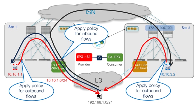
Security Policy Enforcement when the Ext-EPG is the Consumer
If instead the contract’s direction is reversed and the External EPG is configured as the provider of the contract (typically for communications initiated from the data center to connect to an external service), the security policy is consistently applied on the compute leaf node for both legs of the traffic flow.
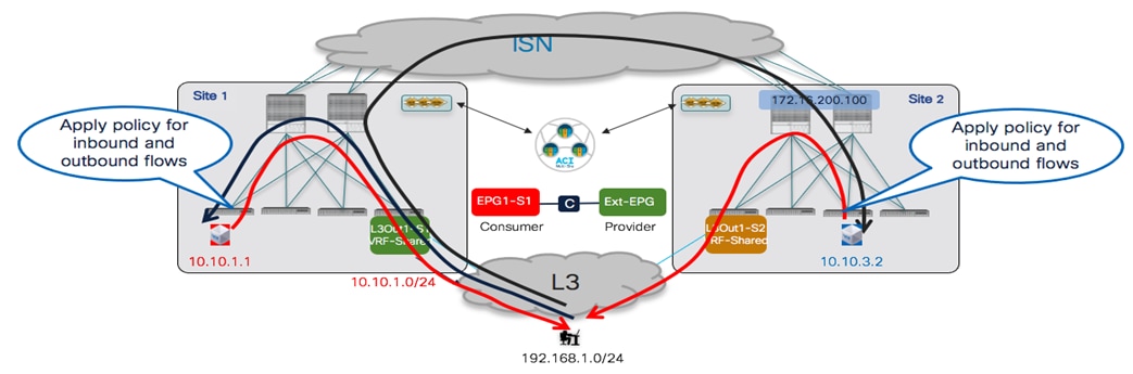
Security Policy Enforcement when the Ext-EPG is the Provider
In this shared service use case, the VRF for the internal EPGs/BDs and the VRF for the L3Out are defined in different Tenants. The configuration steps and the deployment considerations made for the previous use case continue to apply here, with only the following differences:
● The scope of the contract must now be set to “Global”.
● The contract must be defined in a template associated with the “Provider” tenant. Applying this configuration on Nexus Dashboard Orchestrator automatically ensures that on APIC the contract gets exported toward the “Consumer” tenant where it can be seen as a “Contract Interface”, as shown in Figure 106 and Figure 107.
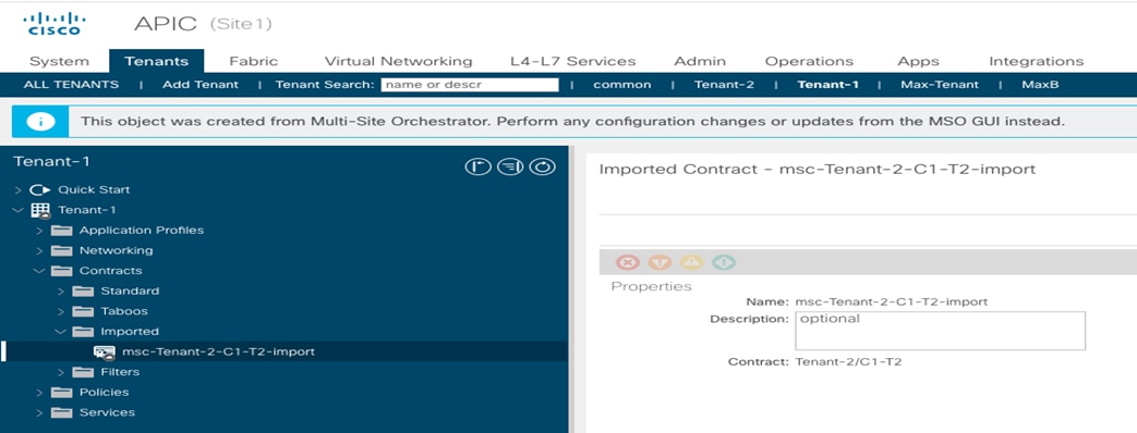
Contract Imported into the Consumer Tenant
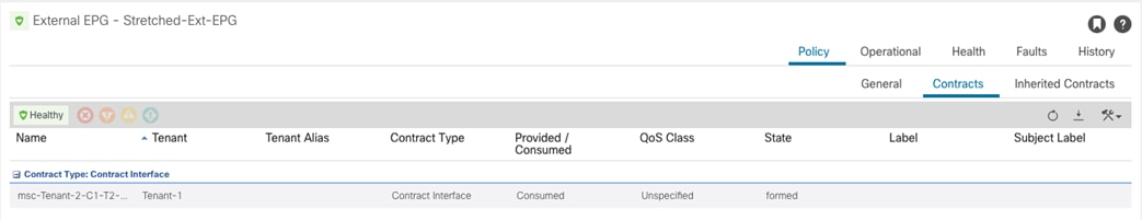
Contract Interface Created on the Consumer Tenant
All the other considerations, including the advertisement of BD subnets toward the external network, remain exactly the same as in the previous use case 2.
In all the use cases previously described, the requirement has always been to have a local L3Out connection available in each fabric part of the Multi-Site domain for outbound communication with external resources. This default behavior in an ACI Multi-Site deployment does not allow to cover a couple of specific scenarios where there may be a need to communicate with resources accessible via the L3Out connection that is only deployed in a specific fabric.
The first scenario is to establish north-south connectivity between an internal endpoint connected to a site and the L3Out connection deployed in a remote site, as shown in Figure 108.

Intersite North-south Connectivity Scenario
The second scenario is the enablement of transit routing between L3Out connections deployed in different sites, as shown in Figure 106.
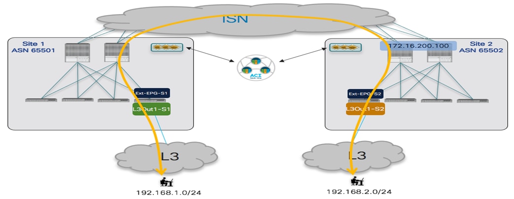
Intersite Transit Routing Scenario
ACI release 4.2(1) and MSO release 2.2(1) introduced support for the “Intersite L3Out” functionality, which allows changing the default Multi-Site behavior to be able to cover the two use cases shown in the figures above, both for intra-VRF and inter-VRF (and/or inter-tenant) deployment scenarios.
It is worth noticing that as of ACI release 5.2(3) and NDO release 3.5(1), intersite L3Out it is not supported in conjunction with the use of Preferred Groups or vzAny. It is hence required to apply specific contract between the EPGs and Ext-EPGs (or between Ext-EPGs) defined in separate sites.
Note: More details around the specific use cases requiring the deployment of the intersite L3Out functionality and the technical aspects of control and data plane behavior can be found in the ACI Multi-Site paper below (in this document the focus is mostly on how to deploy this functionality):
Intersite North-South Connectivity (Intra-VRF)
The first scenario hereby considered is the one displayed in Figure 110 for the establishment of intersite north-south connectivity intra-VRF.
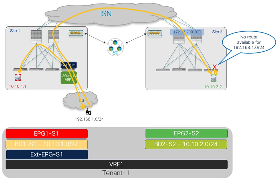
Intersite L3Out for North-south Connectivity (intra-VRF)
As shown above, once the BDs and contracts are properly configured (allowing connectivity between EPG1-S1 and Ext-EPG-S1 and between EP2-S2 and Ext-EPG-S1), two-way north-south communication can be established by default only for endpoints that are connected to the same fabric with the L3Out connection (EPG1-S1 in Site 1). Remote endpoints part of EPG2-S2 are also able to receive inbound traffic flows (leveraging the VXLAN data plane connectivity across the ISN). However, the return communication is not possible as the external prefix 192.168.1.0/24 is not advertised across sites. This default behavior of ACI Multi-Site can be modified through the enablement of the “Intersite L3Out” functionality. The following configuration steps performed on Nexus Dashboard Orchestrator are required to achieve two-way north-south communication between the endpoint in Site 2 part of EPG2-S2 and the external network 192.168.1.0/24.
1. Properly configure BD2-S2 to advertise the IP subnet out of L3Out-S1. This requires making the IP subnet “Advertised Externally” and mapping the BD to the remote L3Out, both actions done at the site level since the BD is locally defined in Site 2. Notice that to be able to associate BD2-S2 defined in SIte2 with L3Out-S1, it is mandatory to have the L3Out object defined on a NDO template. If the L3Out was initially created on APIC, it is possible to import the L3Out object into NDO.

Configuration to Advertise BD2-S2’s Subnet out of L3Out1-S1
2. Configure Ext-EPG-S1 to properly classify incoming traffic. As previously discussed in this document, the use of a “catch-all” 0.0.0.0/0 prefix is quite common when the L3Out provides access to every external destination, but in this specific use case, a more specific prefix is configured as the L3Out likely provides access to a specific set of external resources.

Classification Subnet Configured Under Ext-EPG-S1
3. As explained in greater detail in the ACI Multi-Site paper previously referred above, the Intersite L3Out connectivity is achieved by creating a VXLAN tunnel directly between the compute leaf node, where the internal endpoint is connected, and the BL node connected to the external resource. For this to be possible, it is first of all required to define an external TEP pool for the ACI fabric part of the Multi-Site domain where the L3Out is deployed. This allows to provision a TEP address (part of the specified external TEP pool) for each border leaf node in that fabric, to ensure that the direct VXLAN tunnel can be established from a remote compute leaf node (since all the TEP addresses assigned by default to the fabric leaf and spine nodes are part of the original TEP pool configured during the fabric bring up operation and such pool may not be routable between sites). Even if technically the external TEP pool is only needed for the fabric where the L3Out is deployed, it is recommended to provide one for each fabric part of the Multi-Site domain (just to ensure communication will work right away if/when a local L3Out is created at a later time).
The configuration of the external TEP pool can be done on NDO as part of the “Infra Configuration” workflow for each Pod of the fabrics part of the NDO domain, as shown in Figure 113.
Note: If a fabric part of the NDO domain is deployed as a Multi-Pod fabric, a separate external TEP pool must be specified for each Pod part of the fabric. The external TEP pool can range between a /22 and a /29 prefix.

Configuring the External TEP Pool for each Pod
Once the external TEP pool configuration is pushed to the fabrics, the first result is the provisioning of a dedicated loopback interface on the BL nodes, representing the external TEP address assigned to that node that will be used as a destination of the VXLAN tunnel initiated from the compute node in a remote site. This can be seen for example on the BL node of Site 1 in the output below:
Leaf 104 Site1
Leaf104-Site1# show ip int bri vrf overlay-1
IP Interface Status for VRF "overlay-1"(4)
Interface Address Interface Status
eth1/49 unassigned protocol-up/link-up/admin-up
eth1/49.6 unnumbered protocol-up/link-up/admin-up
(lo0)
eth1/50 unassigned protocol-up/link-up/admin-up
eth1/50.7 unnumbered protocol-up/link-up/admin-up
(lo0)
eth1/51 unassigned protocol-down/link-down/admin-up
eth1/53 unassigned protocol-down/link-down/admin-up
eth1/54 unassigned protocol-down/link-down/admin-up
vlan8 10.1.0.30/27 protocol-up/link-up/admin-up
lo0 10.1.0.69/32 protocol-up/link-up/admin-up
lo1 10.1.232.65/32 protocol-up/link-up/admin-up
lo4 192.168.101.232/32 protocol-up/link-up/admin-up
lo1023 10.1.0.32/32 protocol-up/link-up/admin-up
4. The provisioning of the external TEP pool is not sufficient to trigger the exchange of external prefixes between sites, required to ensure that the outbound flow shown in the previous Figure 110 can be sent toward the BL node in Site 1. For that to happen, it is also required to apply a contract between EPG2-S2 in Site 2 and the Ext-EPG associated to the L3Out in Site 1.

Apply a Contract between EPG2-S2 and Ext-EPG-S1
Once that contract relationship is established, a VPNv4/VPNv6 prefix exchange will be triggered between the spines allowing to advertise the external prefix 192.168.1.0/24 to Site 2 and this will allow for the successful establishment of outbound communication. This is confirmed by looking at the routing table of the compute leaf in Site 2.
Leaf 304 Site2
Leaf304-Site2# show ip route vrf Tenant-1:VRF1
IP Route Table for VRF "Tenant-1:VRF1"
'*' denotes best ucast next-hop
'**' denotes best mcast next-hop
'[x/y]' denotes [preference/metric]
'%<string>' in via output denotes VRF <string>
10.10.2.0/24, ubest/mbest: 1/0, attached, direct, pervasive
*via 10.0.136.66%overlay-1, [1/0], 03:32:38, static, rwVnid: vxlan-2359299
10.10.2.254/32, ubest/mbest: 1/0, attached, pervasive
*via 10.10.2.254, vlan41, [0/0], 1d01h, local, local
192.168.1.0/24, ubest/mbest: 1/0
*via 192.168.101.232%overlay-1, [200/0], 00:00:02, bgp-100, internal, tag 65501, rwVnid: vxlan-3112963
As seen above, the next-hop for the external prefix is the external TEP pool address assigned to the BL node in Site 1. Also, the routing table shows the information that all the traffic destined toward the external destination 192.168.1.0/24 should be encapsulated using the VXLAN ID 3112963 in the header. This value represents the VXLAN ID for the L3Out VRF (VRF1) in Site 1, as shown in the output below:
Leaf 104 Site1
Leaf104-Site1# show vrf Tenant-1:VRF1 detail
VRF-Name: Tenant-1:VRF1, VRF-ID: 41, State: Up
VPNID: unknown
RD: 103:3112963
This VXLAN ID value is added in the VXLAN header to allow the receiving BL node to derive the information of what VRF to perform the Layer 3 lookup for the destination. Since the VXLAN tunnel is directly terminated on the BL node, there is no translation happening on the spines in Site 1 and, as a consequence, the compute leaf node needs to know the correct VXLAN ID representing VRF1 in Site
This VXLAN ID value is added in the VXLAN header to allow the receiving BL node to derive the information of what VRF to perform the Layer 3 lookup for the destination. Since the VXLAN tunnel is directly terminated on the BL node, there is no translation happening on the spines in Site 1 and, as a consequence, the compute leaf node needs to know the correct VXLAN ID representing VRF1 in Site 1. This information is hence communicated from Site 1 to Site 2 as part of the EVPN control plane update, as it can be verified in the BGP routing table of the compute leaf node in Site 2.
Leaf 304 Site2
Leaf304-Site2# show ip bgp 192.168.1.0/24 vrf Tenant-1:VRF1
BGP routing table information for VRF Tenant-1:VRF1, address family IPv4 Unicast
BGP routing table entry for 192.168.1.0/24, version 30 dest ptr 0xa2262588
Paths: (1 available, best #1)
Flags: (0x08001a 00000000) on xmit-list, is in urib, is best urib route, is in HW
vpn: version 218279, (0x100002) on xmit-list
Multipath: eBGP iBGP
Advertised path-id 1, VPN AF advertised path-id 1
Path type: internal 0xc0000018 0x80040 ref 0 adv path ref 2, path is valid, is best path, remote site path
Imported from 103:19890179:192.168.1.0/24
AS-Path: 65501 3 , path sourced external to AS
192.168.101.232 (metric 63) from 10.0.0.66 (172.16.200.1)
Origin IGP, MED not set, localpref 100, weight 0 tag 0, propagate 0
Received label 0
Received path-id 2
Extcommunity:
RT:65501:19890179
SOO:65501:33554415
COST:pre-bestpath:166:2684354560
COST:pre-bestpath:168:3221225472
VNID:3112963
Intersite North-South Connectivity (Inter-VRFs)
The only difference in this scenario is that the L3Out is part of a different VRF (VRF-Shared) compared to the internal endpoint (still part of VRF1).
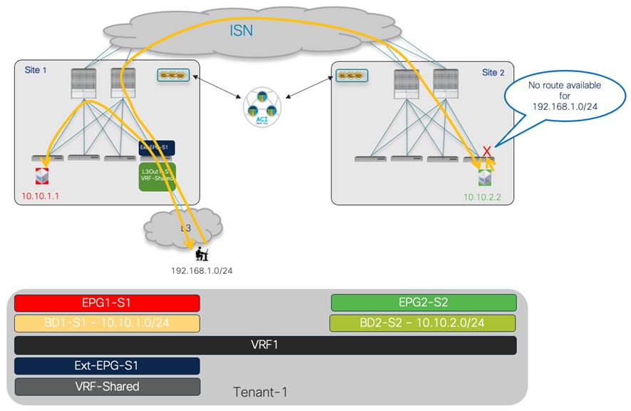
Intersite L3Out for North-South Connectivity (inter-VRF)
The configuration steps 3 and 4 described above remain identical (except the need to ensure the scope of the applied contract is now at least “Tenant”), what now is changing is the configuration required to leak routes between VRFs and be able to properly apply the policy. The same considerations made in the “Use Case 2: Site-Local L3Out Connections to Communicate with External Resources (Inter-VRF/Shared Services inside the Same Tenant)” apply here as well. Figure 116 shows the configuration required for the subnet defined under the BD and EPG (assuming EPG1-S1 is the provider of the contract, else the subnet under the EPG is not required) and the subnet configuration under Ext-EPG-S1.
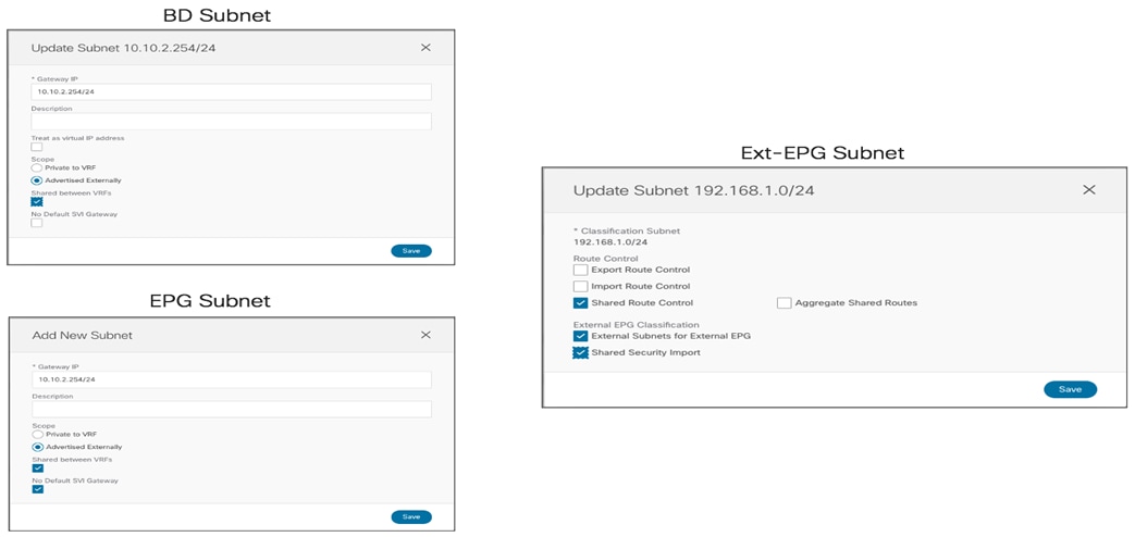
Provisioning the Configuration for the Intersite North-South inter-VRF Use Case
It is worth noticing that the same configuration must pre provisioned from NDO for the use cases previously described in this section if the VRFs are defined in separate tenants. The only difference us that in such case the scope of the contract must be “Global” and needs to be defined in the Provider Tenant. More information can be found in the “Use Case 3: Site-Local L3Out Connections to Communicate with External Resources (Inter-VRF/Shared Services between Different Tenants)” section.
Intersite Transit Routing Connectivity (Intra-VRF)
In the previous use cases, the intersite L3Out functionality was introduced to allow communication across sites between endpoints and external resources. A specific use case where intersite L3Out is handy is the one where ACI Multi-Site plays the role of a “distributed core” interconnecting separate external network domain. This deployment model is referred to as intersite transit routing and shown in Figure 115 for the use case where both L3Out connections are part of the same VRF1 routing domain.
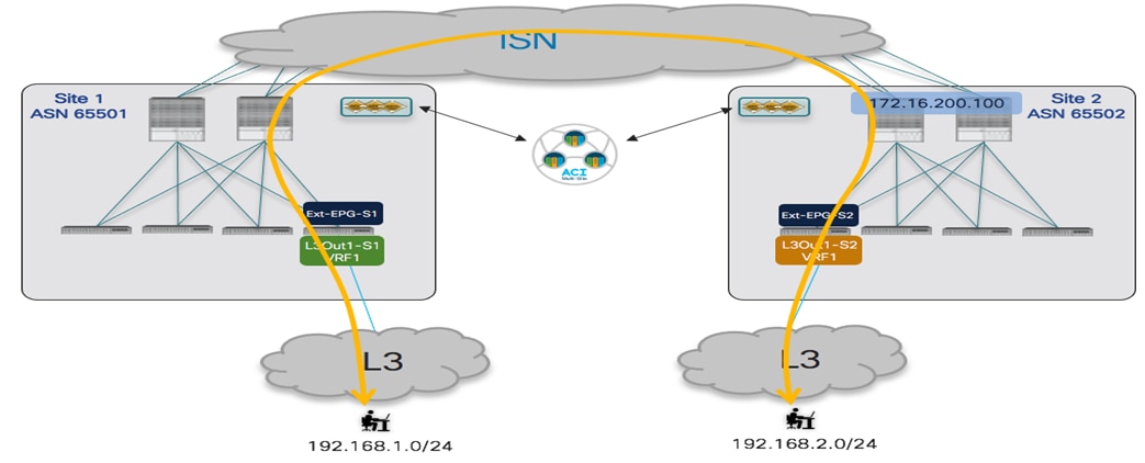
Intersite Transit Routing Connectivity (Intra-VRF)
A separate External EPG is defined for each L3Out connection in this case, as they provide connectivity to different external routed domains that require to communicate with each other. The following are the provisioning steps required to implement this scenario.
● Define one or more prefixes associated to the Ext-EPGs to ensure incoming traffic can be properly classified. If the only deployed L3Outs were the ones shown in figure above, a simple 0.0.0.0/0 prefix could be used for both of them. In a real-life scenario, however, it would be common to have different L3Out connections being used to provide access to all the other external resources, so more specific prefixes are specified for the Ext-EPGs of the L3Out connections enabling intersite transit routing.

Configuration of classification subnets on Ext-EPGs in Site 1 and 2
● Ensure that the prefixes learned on each L3Out can be advertised out of the remote L3Out. In the specific example discussed in this section, the IP prefix 192.168.1.0/24 is received on the L3Out in Site 1 and should be advertised out of the L3Out in Site 2, and vice versa for the 192.168.2.0/24 prefix.

Announcing Specific Prefixes out of the L3Out in Each Site
● The last step to be able to successfully enable intersite transit routing consists in creating a security policy between the Ext-EPGs associated to the L3Outs deployed in different sites. In the example in Figure 120, Ext-EPG-S1 in Site 1 is providing the contract C1 that is then consumed by Ext-EPG-S2 in Site 2.

Applying a Security Policy Between Ext-EPGs
Once the provisioning steps above have been deployed to the APIC domains in Site 1 and Site 2, intersite transit connectivity can be established. It is possible verify on the BL nodes in each site that the remote external prefixes are indeed received:
Leaf 104 Site1
Leaf104-Site1# show ip route vrf Tenant-1:VRF1
IP Route Table for VRF "Tenant-1:VRF1"
'*' denotes best ucast next-hop
'**' denotes best mcast next-hop
'[x/y]' denotes [preference/metric]
'%<string>' in via output denotes VRF <string>
192.168.1.0/24, ubest/mbest: 1/0
*via 172.16.1.1%Tenant-1:VRF1, [20/0], 00:35:20, bgp-65501, external, tag 3
192.168.2.0/24, ubest/mbest: 1/0
*via 192.168.103.229%overlay-1, [200/0], 00:05:33, bgp-65501, internal, tag 100, rwVnid: vxlan-2359299
Leaf 201 Site2
Leaf201-Site2# show ip route vrf Tenant-1:VRF1
IP Route Table for VRF "Tenant-1:VRF1"
'*' denotes best ucast next-hop
'**' denotes best mcast next-hop
'[x/y]' denotes [preference/metric]
'%<string>' in via output denotes VRF <string>
192.168.1.0/24, ubest/mbest: 1/0
*via 192.168.101.232%overlay-1, [200/0], 00:03:02, bgp-100, internal, tag 65501, rwVnid: vxlan-3112963
192.168.2.0/24, ubest/mbest: 1/0
*via 172.16.2.1%Tenant-1:VRF1, [20/0], 00:38:25, bgp-100, external, tag 30
As shown above, the prefix 192.168.2.0/24 is learned in Site 1 via the VPNv4 control plane sessions established between the spines and installed on the local BL node with the next-hop representing the external TEP address assigned to the BL node in Site 2 (192.168.103.229) and the specific VXLAN ID to use representing VRF1 in Site 2 (vxlan-2359299). Similar considerations apply to the 192.168.1.0/24 that is advertised from Site 1 to Site 2.
From a policy enforcement perspective, the contract is always applied inbound on the BL node where the traffic is received from the external network (Figure 121).
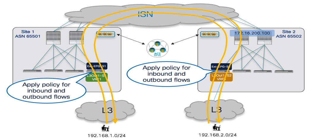
Security Policy Applied Always Inbound on the BL Nodes
For this to be possible, it is required that each BL node knows the class-ID for the local and remote external prefix, as it can be verified using the commands below.
Leaf 104 Site1
Leaf104-Site1# vsh -c 'show system internal policy-mgr prefix'
Vrf-Vni VRF-Id Table-Id Table-State VRF-Name Addr Class Shared Remote Complete
======= ====== =========== ======= ============================ ================================= ====== ====== ====== ========
3112963 41 0x29 Up Tenant-1:VRF1 192.168.1.0/24 49156 True True False
3112963 41 0x29 Up Tenant-1:VRF1 192.168.2.0/24 16392 True True False
Leaf 201 Site2
Leaf201-Site2# vsh -c 'show system internal policy-mgr prefix'
Vrf-Vni VRF-Id Table-Id Table-State VRF-Name Addr Class Shared Remote Complete
======= ====== =========== ======= ============================ ================================= ====== ====== ====== ========
2359299 31 0x1f Up Tenant-1:VRF1 192.168.2.0/24 49161 False True False
2359299 31 0x1f Up Tenant-1:VRF1
As noticed above, the Class-IDs for the prefixes are different in each site and they correspond to the values associated with the local Ext-EPG and to the shadow Ext-EPG that is created as a result of the establishment of the contractual relationship.

Class-ID Values for Local and Shadow Ext-EPGs in Each Site
As shown above, the establishment of the contract between the Ext-EPGs causes the instantiation of the whole shadow L3Out (with associated Ext-EPG) in each remote APIC domain (L3Out-S2 is the shadow object in the APIC in Site 1, whereas L3Out-S1 is the shadow object in the APIC in Site 2). The creation of those shadow EPG objects allows them to map the specific IP prefixes configured under the Ext-EPGs with the proper Class-ID values.
Being able to associate the remote external prefixes with the right Class-ID value is critical for applying the policy inbound to the BL node. This is confirmed by looking at the zoning-rule tables for the BL nodes in Site 1 and Site 2.
Leaf 104 Site1
Leaf104-Site1# show zoning-rule scope 3112963
+---------+--------+--------+----------+----------------+---------+---------+-------------+----------+----------------------+
| Rule ID | SrcEPG | DstEPG | FilterID | Dir | operSt | Scope | Name | Action | Priority |
+---------+--------+--------+----------+----------------+---------+---------+-------------+----------+----------------------+
| 4156 | 0 | 0 | implicit | uni-dir | enabled | 3112963 | | deny,log | any_any_any(21) |
| 4232 | 0 | 0 | implarp | uni-dir | enabled | 3112963 | | permit | any_any_filter(17) |
| 4127 | 0 | 15 | implicit | uni-dir | enabled | 3112963 | | deny,log | any_vrf_any_deny(22) |
| 4124 | 0 | 49154 | implicit | uni-dir | enabled | 3112963 | | permit | any_dest_any(16) |
| 4212 | 0 | 49153 | implicit | uni-dir | enabled | 3112963 | | permit | any_dest_any(16) |
| 4234 | 0 | 32771 | implicit | uni-dir | enabled | 3112963 | | permit | any_dest_any(16) |
| 4199 | 49156 | 16392 | default | uni-dir-ignore | enabled | 3112963 | Tenant-1:C1 | permit | src_dst_any(9) |
| 4213 | 16392 | 49156 | default | bi-dir | enabled | 3112963 | Tenant-1:C1 | permit | src_dst_any(9) |
+---------+--------+--------+----------+----------------+---------+---------+-------------+----------+----------------------+
Note: 3112963 is the Segment-ID value for VRF1 in Site 1 (this information can be retrieved using the “show vrf <VRF_name> detail” command).
Leaf 201 Site2
Leaf201-Site2# show zoning-rule scope 2359299
+---------+--------+--------+----------+----------------+---------+---------+-------------+----------+----------------------+
| Rule ID | SrcEPG | DstEPG | FilterID | Dir | operSt | Scope | Name | Action | Priority |
+---------+--------+--------+----------+----------------+---------+---------+-------------+----------+----------------------+
| 4183 | 0 | 0 | implicit | uni-dir | enabled | 2359299 | | deny,log | any_any_any(21) |
| 4108 | 0 | 0 | implarp | uni-dir | enabled | 2359299 | | permit | any_any_filter(17) |
| 4213 | 0 | 15 | implicit | uni-dir | enabled | 2359299 | | deny,log | any_vrf_any_deny(22) |
| 4214 | 0 | 32772 | implicit | uni-dir | enabled | 2359299 | | permit | any_dest_any(16) |
| 4212 | 0 | 32771 | implicit | uni-dir | enabled | 2359299 | | permit | any_dest_any(16) |
| 4201 | 0 | 16392 | implicit | uni-dir | enabled | 2359299 | | permit | any_dest_any(16) |
| 4109 | 49161 | 49162 | default | bi-dir | enabled | 2359299 | Tenant-1:C1 | permit | src_dst_any(9) |
| 4182 | 49162 | 49161 | default | uni-dir-ignore | enabled | 2359299 | Tenant-1:C1 | permit | src_dst_any(9) |
+---------+--------+--------+----------+----------------+---------+---------+-------------+----------+----------------------+
Note: 2359299 is the Segment-ID value for VRF1 in Site 2.
Intersite Transit Routing Connectivity (Inter-VRFs)
Intersite transit routing communication is also possible in the shared service scenario, shown in Figure 123, where the L3Outs deployed in each site are part of different VRFs.
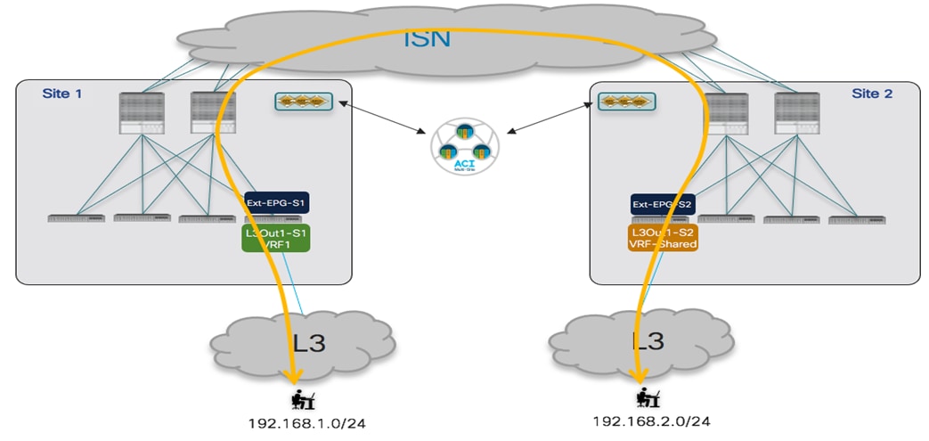
Intersite Transit Routing Connectivity (Inter-VRFs)
The required provisioning steps are very similar to the intra-VRF scenario previously discussed.
● Properly configure the flags on the Ext-EPGs associated with the IP prefixes used for classifying the traffic. The setting of those flags is required to leak the IP prefixes between VRFs and to properly install in the remote BL Nodes the Class-ID value for those prefixes.
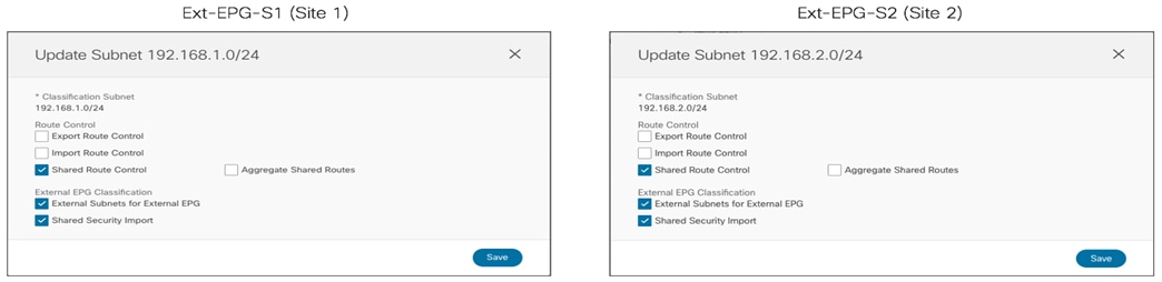
Setting the Flags for Route-leaking and Class-ID Installation
● Ensure that the prefixes learned on each L3Out can be advertised out of the remote L3Out. This requires the exact configuration previously shown in Figure 119 for the intra-VRF use case.
● Apply a security contract between the Ext-EPGs. This can be done with the same configuration shown in Figure 120, with the only difference that the scope the contract C1 must be set as “Tenant” or “Global”, depending on if the VRFs are part of the same Tenant or defined in separate Tenants.
As shown in Figure 125, the intersite transit routing communication is then established across fabrics leveraging the fact that the BL node in Site 1 would encapsulate traffic toward the remote BL node in Site 2 using the VRF Segment-ID representing the Shared-VRF in that remote fabric, and vice versa.
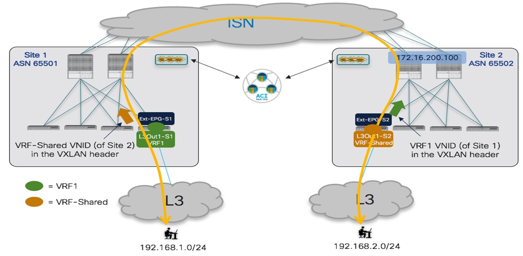
Using Remote VRF Segment-ID when Sending Traffic to the Remote Site
This can be verified by looking at the output below.
Leaf 104 Site1
Leaf104-Site1# show ip route vrf Tenant-1:VRF1
IP Route Table for VRF "Tenant-1:VRF1"
'*' denotes best ucast next-hop
'**' denotes best mcast next-hop
'[x/y]' denotes [preference/metric]
'%<string>' in via output denotes VRF <string>
192.168.1.0/24, ubest/mbest: 1/0
*via 172.16.1.1%Tenant-1:VRF1, [20/0], 07:37:22, bgp-65501, external, tag 3
192.168.2.0/24, ubest/mbest: 1/0
*via 192.168.103.229%overlay-1, [200/0], 01:12:10, bgp-65501, internal, tag 100, rwVnid: vxlan-2097156
Note: 2097156 is the Segment-ID value for VRF-Shared in Site 2 (this information can be retrieved using the “show vrf <VRF_name> detail” command).
Leaf 201 Site2
Leaf201-Site2# show ip route vrf Tenant-1:VRF-Shared
IP Route Table for VRF "Tenant-1:VRF-Shared"
'*' denotes best ucast next-hop
'**' denotes best mcast next-hop
'[x/y]' denotes [preference/metric]
'%<string>' in via output denotes VRF <string>
192.168.1.0/24, ubest/mbest: 1/0
*via 192.168.101.232%overlay-1, [200/0], 00:02:07, bgp-100, internal, tag 65501, rwVnid: vxlan-3112963
192.168.2.0/24, ubest/mbest: 1/0
*via 172.16.2.1%Tenant-1:VRF-Shared, [20/0], 01:16:31, bgp-100, external, tag 30
Note: 3112963 is the Segment-ID value for VRF1 in Site 1.
From the point of view of the policy enforcement, the same behavior previously shown in Figure 121 continues to be valid also in the inter-VRF scenario. The only difference is that the Class-ID for the remote external prefix is now installed as a result of the “Shared Security Import” flag setting shown in Figure 124 for the Ext-EPGs. This can be verified using the same commands used for the intra-VRF use case.
Leaf 104 Site1
Leaf104-Site1# vsh -c 'show system internal policy-mgr prefix'
Vrf-Vni VRF-Id Table-Id Table-State VRF-Name Addr Class Shared Remote Complete
======= ====== =========== ======= ============================ ================================= ====== ====== ====== ========
3112963 41 0x29 Up Tenant-1:VRF1 192.168.1.0/24 10930 True True False
3112963 41 0x29 Up Tenant-1:VRF1 192.168.2.0/24 10934 True True False
Leaf 201 Site2
Leaf201-Site2# vsh -c 'show system internal policy-mgr prefix'
Vrf-Vni VRF-Id Table-Id Table-State VRF-Name Addr Class Shared Remote Complete
======= ====== =========== ======= ============================ ================================= ====== ====== ====== ========
2097156 34 0x22 Up Tenant-1:VRF-Shared 192.168.1.0/24 5492 True True False
2097156 34 0x22 Up Tenant-1:VRF-Shared 192.168.2.0/24 32771 True True False
As can be seen also in Figure 126, the class-ID values assigned to the local and shadow Ext-EPGs are now different from the ones used for the intra-VRF use case, as global values must be used to ensure they are unique across VRFs.

Class-ID Values for Local and Shadow Ext-EPGs in Each Site
The configuration of the zoning-rule entries on the BL nodes allows to confirm that the security policy is always applied inbound on the BL node that is receiving the traffic flow from the external network.
Leaf 104 Site1
Leaf104-Site1# show zoning-rule scope 3112963
+---------+--------+--------+----------+----------------+---------+---------+-------------+-----------------+----------------------+
| Rule ID | SrcEPG | DstEPG | FilterID | Dir | operSt | Scope | Name | Action | Priority |
+---------+--------+--------+----------+----------------+---------+---------+-------------+-----------------+----------------------+
| 4156 | 0 | 0 | implicit | uni-dir | enabled | 3112963 | | deny,log | any_any_any(21) |
| 4232 | 0 | 0 | implarp | uni-dir | enabled | 3112963 | | permit | any_any_filter(17) |
| 4127 | 0 | 15 | implicit | uni-dir | enabled | 3112963 | | deny,log | any_vrf_any_deny(22) |
| 4124 | 0 | 49154 | implicit | uni-dir | enabled | 3112963 | | permit | any_dest_any(16) |
| 4212 | 0 | 49153 | implicit | uni-dir | enabled | 3112963 | | permit | any_dest_any(16) |
| 4234 | 0 | 32771 | implicit | uni-dir | enabled | 3112963 | | permit | any_dest_any(16) |
| 4213 | 10930 | 14 | implicit | uni-dir | enabled | 3112963 | | permit_override | src_dst_any(9) |
| 4199 | 10930 | 10934 | default | uni-dir-ignore | enabled | 3112963 | Tenant-1:C1 | permit | src_dst_any(9) |
| 4206 | 10934 | 10930 | default | bi-dir | enabled | 3112963 | Tenant-1:C1 | permit | src_dst_any(9) |
+---------+--------+--------+----------+----------------+---------+---------+-------------+-----------------+----------------------+
Note: 3112963 is the Segment-ID value for VRF1 in Site 1 (this information can be retrieved using the “show vrf <VRF_name> detail” command).
Leaf 201 Site2
Leaf201-Site2# show zoning-rule scope 2097156
+---------+--------+--------+----------+----------------+---------+---------+-------------+----------+------------------------+
| Rule ID | SrcEPG | DstEPG | FilterID | Dir | operSt | Scope | Name | Action | Priority |
+---------+--------+--------+----------+----------------+---------+---------+-------------+----------+------------------------+
| 4182 | 0 | 0 | implicit | uni-dir | enabled | 2097156 | | deny,log | any_any_any(21) |
| 4109 | 0 | 0 | implarp | uni-dir | enabled | 2097156 | | permit | any_any_filter(17) |
| 4190 | 0 | 15 | implicit | uni-dir | enabled | 2097156 | | deny,log | any_vrf_any_deny(22) |
| 4198 | 5492 | 32771 | default | uni-dir-ignore | enabled | 2097156 | Tenant-1:C1 | permit | src_dst_any(9) |
| 4176 | 32771 | 5492 | default | bi-dir | enabled | 2097156 | Tenant-1:C1 | permit | src_dst_any(9) |
| 4222 | 5492 | 0 | implicit | uni-dir | enabled | 2097156 | | deny,log | shsrc_any_any_deny(12) |
+---------+--------+--------+----------+----------------+---------+---------+-------------+----------+------------------------+
Note: 2097156 is the Segment-ID value for VRF-Shared in Site 2.
The same configuration discussed in this section would be required to establish inter-VRF transit routing connectivity when the VRFs are defined in different tenants. The only thing to ensure in that case is that the contract is defined with scope “Global” as part of the Provider tenant.
Service Node Integration with ACI Multi-Site
The basic assumption for service node integration with ACI Multi-Site is that one (or more) set of dedicated service nodes are deployed in each fabric part of the Multi-Site domain. The support of clustered services across sites is in fact limited and won’t be considered in the context of this paper, as it is not the most common nor recommended approach in a Multi-Site deployment.
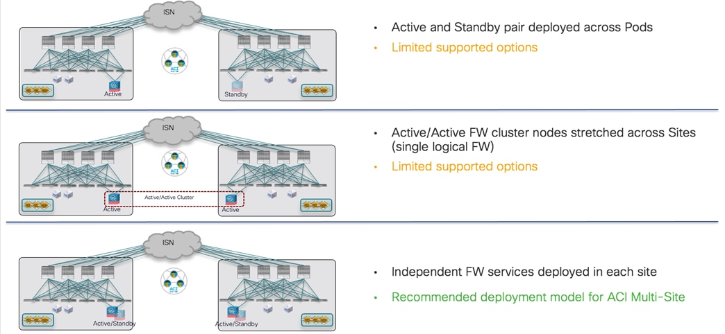
Service Node Integration with ACI Multi-Site
The first immediate consequence is that each specific service node functionality should be deployed in each fabric in the most possible resilient way. Figure 128 shows three different ways to achieve local service node resiliency inside each fabric (the specific example in the figure refers to firewalling services, but the same considerations apply to other types of service nodes):
● Deployment of an active/standby cluster: this usually implies that the whole cluster is seen as a single MAC/IP addresses pair, even if there are some specific service nodes on the market who do not preserve the active MAC address as a result of a node switchover event (we’ll discuss also this case in more details below).
● Deployment of an active/active cluster: in the specific case of a Cisco ASA/FTD deployment, the whole cluster can be referenced by a single MAC/IP addresses pair (owned by all the nodes belonging to the cluster). Other active/active implementations on the market may instead result in having each cluster node owning a dedicated and unique MAC/IP pair.
Note: The deployment of an A/A cluster in a fabric part of a Multi-Site domain requires the minimum ACI release 5.2(2e) to be used in that site.
● Deployment of multiple independent service nodes in each fabric, each one referenced by a unique MAC/IP addresses pair.
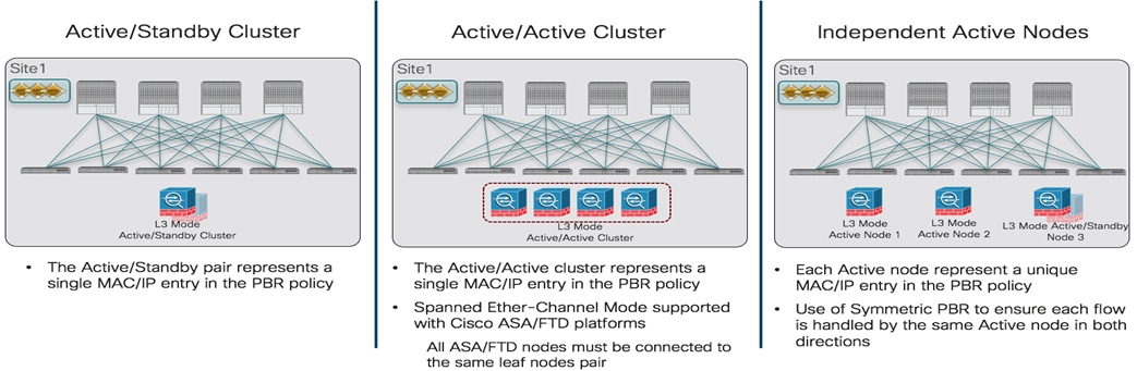
Different Options for the Resilient Deployment of a Service Node Function in an ACI Fabric
Note: The focus in this paper is the deployment of service nodes in Layer 3 mode, as it is the most common deployment scenario. Service graph configuration supports also the use of Layer 1 and Layer 2 PBR, for more information please refer to the paper below:
Independently from the specific redundancy deployment option of choice, the configuration required to define the service node and the associated PBR policy must always be performed at the APIC level, for each ACI fabric part of a Multi-Site domain. As it will be clarified better in the following sections, the different redundancy options shown in Figure 128 can be deployed based on the specific service node and PBR policy configuration that is created on APIC. This configuration also varies depending on if one or more service nodes must be inserted in the communication between EPGs, so those scenarios will be considered independently.
For a more detailed discussion of service node integration options, please refer to the paper below:
Service Graph with PBR with Multi-Site for the Insertion of a Single Service Node
The first use case to consider is the insertion of a single service node to redirecting the traffic flows established between two EPGs. Different scenarios can be deployed, depending on if the EPGs are deployed for internal endpoints or associated with L3Outs (Ext-EPG), and if they are part of the same VRF or different VRFs (and/or Tenants).
Independently from the specific use case, the first step consists in defining a logical service node for each fabric that is part of the Multi-Site domain. As shown in Figure 129 below, the creation of this single logical service node must be performed at the APIC controller level and not from NDO. In the specific example below, the configuration leverages two firewall nodes (usually referred to as “concrete devices”) in each site but similar considerations apply when deploying a different type of service node (server load balancer, etc.).

Deployment of a Single Service Node on APIC
Note: the configuration shown above must be performed on all the APIC controllers managing the fabrics that are part of the Multi-Site domain. Notice also that the service node must be configured as “unmanaged” by unchecking the “Managed” flag, which is the only possible option for integration with Multi-Site.
The two concrete firewall nodes shown above are deployed as part of a cluster (active/standby or active/active) or as independent nodes, based on the specific redundancy option of choice (one of the models shown in previous Figure 128). For more specific information on how to build a cluster configuration with Cisco ASA/FTD firewall devices, please refer to the documentation below:
Independently from the specific redundancy model of choice, each APIC controller exposes to NDO a single logical service node (in the example in the figure above named “Site1-FW”), which is connected to the fabric via a single logical one-arm interface (named “One-Arm-Site1-FW”). Those specific objects are then used when provisioning the service graph with PBR configuration on NDO, as it will be shown later in this section.
Once the logical firewall service node is defined for each fabric, the second configuration step that must be performed at the APIC level is the definition of the PBR policy. Figure 130 shows the creation of the PBR policy for the active/standby and active/active cluster options supported with Cisco firewalls: in this case, a single MAC/IP pair is specified in the policy, since it represents the entire firewall cluster (i.e. it is assigned to all the active firewall nodes in the cluster). The redirection for each fabric in this case is always performed to the specific MAC/IP value, that could be deployed on a single concrete device (active/standby cluster) or on many concrete devices (independent nodes).
Note: Starting from ACI Release 5.2(1), the configuration of the MAC address in the PBR policy is not mandatory anymore and the MAC associated to the specified IP address can instead be dynamically discovered. This new functionality requires the enablement of tracking for the PBR policy. For more information on this new PBR functionality, please refer to the paper below:
https://www.cisco.com/c/en/us/solutions/collateral/data-center-virtualization/application-centric-infrastructure/white-paper-c11-739971.html

Definition of the PBR Policy for a Firewall Cluster (single MAC/IP pair)
Figure 131 shows instead of the PBR policy that is required when the logical firewall service node is seen as separate MAC/IP addresses pairs: this is the case when deploying independent service nodes in each fabric or even with some third-party firewall cluster implementations. The redirection of traffic happens in this case to different MAC/IP addresses on a per-flow basis and functionality called “symmetric PBR” (enabled by default on ACI leaf nodes starting from EX models and newer) ensures that both legs of the same traffic flow are always redirected to the same MAC/IP pair.

Definition of the PBR Policy for Independent” Firewall Nodes (Multiple MAC/IP Pairs)
The name of the created PBR policy (“PBR-FW-Site1 in the specific examples in Figure 130 and Figure 131) is then exposed to Nexus Dashboard Orchestrator to be used for the provisioning of the service graph with PBR configuration.
Note: A similar configuration is needed on the other APIC controllers of the fabrics part of the Nexus Dashboard Orchestrator domain.
When defining the PBR policy to redirect traffic to the MAC/IP addresses pairs, and independently from the use of the new 5.2(1) dynamic MAC discovery functionality previously mentioned, it is always a best practice recommendation to create an associated “tracking” configuration, ensuring that the fabric can constantly verify the health of the service node. When multiple MAC/IP pairs are used, the importance of tracking is evident to ensure that the failed node associated with a specific MAC/IP value stops being used for traffic redirection. But there are convergence improvements in using tracking also in the scenario (as the Cisco active/active firewall cluster) where multiple nodes inside a fabric use the same MAC/IP value. For more information on how to configure service node tracking in an ACI fabric, please refer to the documentation below:
The use cases discussed in this section for insertion of a firewall service node using service graph with PBR are highlighted in Figure 132.
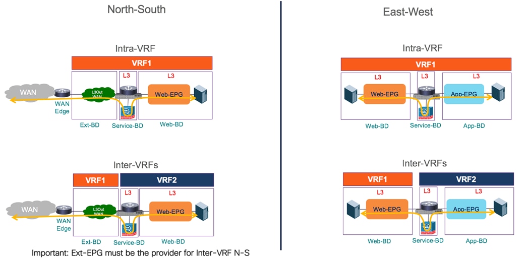
Service Graph with PBR for Insertion of Firewall Service Node
As shown above, the consumer and provider EPGs can be part of the same VRF (and tenant) or also deployed in separate VRFs (and tenants, if required). Also, in the most common deployment model the Firewall node is deployed in Layer 3 mode and connected to a Service BD in one-arm mode. Doing this simplifies the routing configuration on the Firewall (a simple static default route pointing to the Service BD IP address is required), but when preferred it is also possible to connect the inside and outside interfaces of the Firewall to separate BDs (two-arms mode).
Note: Service node insertion using service graph with PBR is not supported for the intersite transit routing use case (i.e. L3Out to L3Out communication). Hence, only a “regular” ACI contract can be applied in that case between L3Outs defined in different sites, as previously discussed in the “Intersite Transit Routing Connectivity (Intra-VRF)” and “Intersite Transit Routing Connectivity (Inter-VRFs)” sections.
Firewall Insertion for North-South Traffic Flows (Intra-VRF)
The first use case to provision is the one requiring the insertion of a firewall service for intra-VRF north-south connectivity.
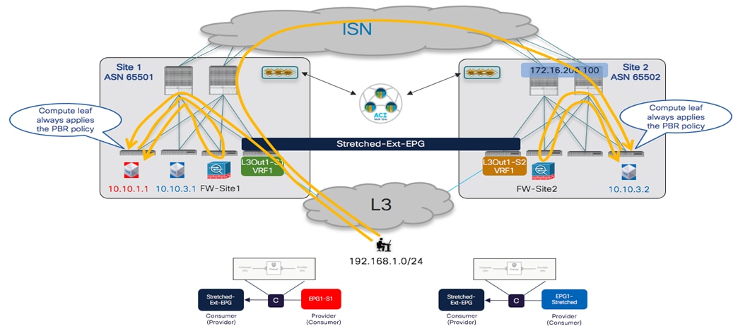
PBR Policy Applied on the Compute Leaf Nodes for Inbound Traffic Flows
Figure 133 shows how the PBR policy is always applied on the compute leaf nodes for all inbound traffic flows, no matter the specific L3Out receiving the traffic. This behavior requires the VRF to have the “Policy Control Enforcement Direction” configured as “Ingress”, which is the default value for all the VRFs created on APIC or NDO.

Default VRF Setting for Policy Control Enforcement Direction
The same behavior applies to the outbound traffic flow, and this is the key functionality that ensures that redirection happens to the same firewall services node already used for the inbound flow (the leveraged firewall services are always in the same fabric where the internal endpoint is connected).
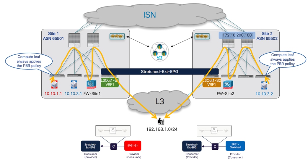
PBR Policy applied on the Compute Leaf Nodes for Outbound Traffic Flows
Notice that this is always the case independently from the specific L3Out connection that is used to communicate with the external devices: the outbound traffic from endpoint 10.10.3.2 normally leverages the local L3Out, even if the inbound flows may have been received on the L3Out of Site1 (as shown in previous Figure 133).
The provisioning steps to be performed on NDO to integrate the firewall for north-south traffic flows (intra-VRF) are described below.
● Configure the subnet of the consumer and provider BDs to ensure they can be advertised out of the L3Out in each site. This requires configuring the BD subnets as “Advertised Externally” and mapping the BDs to the specific L3Outs where the prefix should be advertised, as described in the previous “Connectivity to the External Layer 3 Domain” section.
● Configure the External EPG to properly classify incoming traffic. Assuming a stretched Ext-EPG is deployed, it is common to specify a “catch-all” 0.0.0.0/0 prefix with the associated “External Subnets for External EPGs” flag set.
● Define the “service BD” used to connect the firewall nodes deployed in each fabric. This BD must be provisioned from NDO in a template associated with all the sites. The BD is configured as a Layer 2 stretched object, but there is no need to enable BUM traffic forwarding (which allows preventing cross-site traffic flooding for this specific BD). There is also not a requirement to configure an EPG for the firewall nodes connected to this BD, as that will be automatically created when deploying the service graph.

Provisioning of the Firewall “Service BD”
Note: A single “Service BD” is deployed in this example, as the firewall is configured in “one-arm” mode (as previously shown in Figure 130). If the firewall was instead deployed in “two-arms” mode, two separate “service BDs” would be provisioned, one for each firewall interface. Also, at the time of writing this paper, it is not supported to insert in a service graph a service node that is connected to the fabric via an L3Out connection.
● Create the service graph on the Nexus Dashboard Orchestrator for firewall insertion: assuming that the service node needs to be inserted for communication between endpoints connected to different fabrics, the service graph should be defined in the template associated with all the sites part of the Multi-Site domain (i.e. the service graph is provisioned as a ‘stretched’ object). As shown in Figure 137, the configuration for the service graph is provisioned in two parts: first, at the global template level to specify which service node should be inserted (a firewall in this specific example). Second, at the site level to map the specific logical firewall device that has been defined on APIC and it is now exposed to Nexus Dashboard Orchestrator (see previous Figure 129).

Definition of the Service Graph on NDO
● Define a contract and associate to it the service graph. The contract is usually defined in a template mapped to all the sites and in the example in Figure 138, a “Permit-All” filter is associated with the contract to ensure that all traffic is redirected to the firewall. It is possible to change this behavior and make the filter more specific, if the goal is instead to redirect to the firewall only specific traffic flows.

Define a Contract with Associated Service Graph (Global Template Level)
Also, once the service graph is associated with the contract, it is then required to specify the BD(s) where the firewall logical node is connected. In our specific example the firewall is connected in one-arm mode, hence it is possible to specify the same “Service-BD” for both consumer and provider firewall connectors (interfaces). Notice also that the “Service-BD” must be associated with the connectors at the global template level, which is the main reason why that BD must be provisioned as a stretched object available in all the sites.
It is also required to apply a configuration at the site-local level, to be able to associate the PBR policy to each service node interface (consumer and provider connectors). As shown in Figure 139, in our specific example where the service nodes are connected in one-arm mode, the same PBR policy is applied for both connectors, but that would not be the case when the firewall is connected in two-arms mode. Also, in specific service-graph deployments, there may be needed to apply the PBR policy only for one interface (i.e. for one specific direction of traffic) and not for both (for example for SLB deployments where only return traffic originated from the server farm must be redirected to the SLB node).

Associate the PBR Policy to the Service Node’s Interfaces
● The last provisioning step consists in applying the previously defined contract between the internal EPGs and the external EPG. As previously discussed in the “Connectivity to the External Layer 3 Domain” section, the definition of a stretched external EPG is recommended for the L3Outs deployed across sites that provide access to the same set of external resources, as it simplifies the application of the security policy.
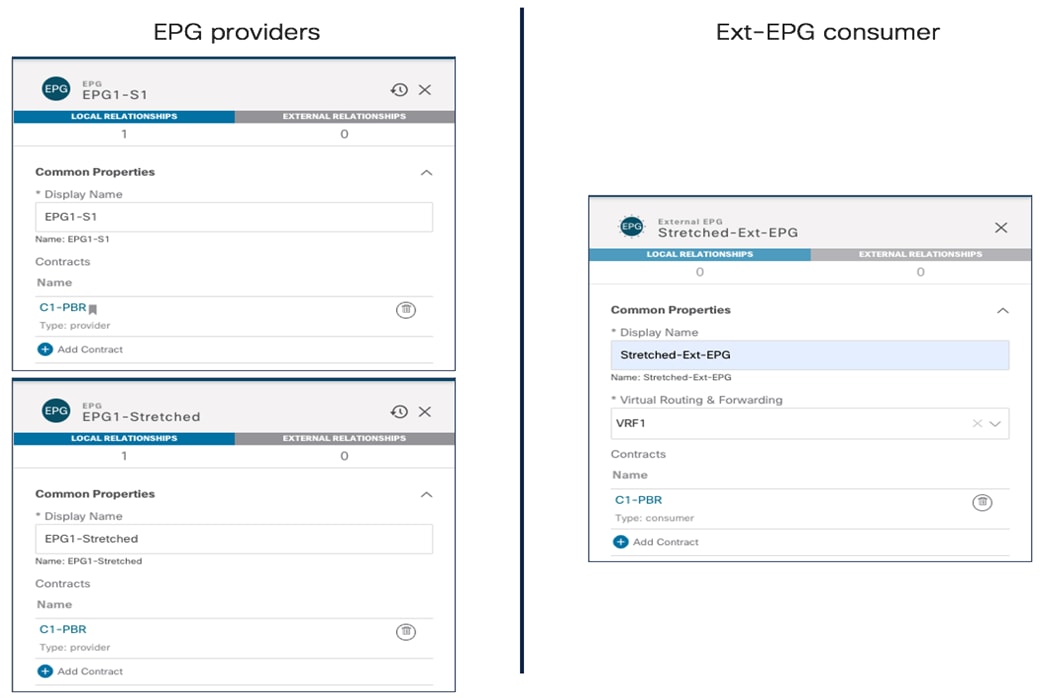
Applying the Contract to Consumer and Provider EPGs
In the infra-VRF scenario discussed in this section, it does not matter which side is the provider or the consumer, the PBR policy is always applied on the compute leaf node anyway, as long as the VRF has the “Policy Control Enforcement Direction” set as “Ingress” (default configuration).
Note: As of NDO release 3.1(1), vzAny cannot be used in conjunction with a contract that has associated a service graph. The only option to apply a PBR policy between two EPGs (internal and/or external) consists hence in creating a specific contract, as in the example above.
Once the provisioning steps described above are completed, a separate service graph is deployed in each APIC domain and north-south traffic flows start getting redirected through the firewall nodes. Figure 141 below shows how to verify that the service graphs have been successfully rendered on APIC (verify there are no faults highlighting deployment issues).

Rendering of the Service Graph on the APIC Controller
It is also possible to verify on the compute node that the traffic is properly redirected to the firewall node, as highlighted in the output below.
Leaf 101 Site1
Leaf101-Site1# show zoning-rule scope 3112963
+---------+--------+--------+----------+----------------+---------+---------+------+------------------+----------------------+
| Rule ID | SrcEPG | DstEPG | FilterID | Dir | operSt | Scope | Name | Action | Priority |
+---------+--------+--------+----------+----------------+---------+---------+------+------------------+----------------------+
| 4194 | 0 | 0 | implicit | uni-dir | enabled | 3112963 | | deny,log | any_any_any(21) |
| 4203 | 0 | 0 | implarp | uni-dir | enabled | 3112963 | | permit | any_any_filter(17) |
| 4227 | 0 | 15 | implicit | uni-dir | enabled | 3112963 | | deny,log | any_vrf_any_deny(22) |
| 4217 | 0 | 32771 | implicit | uni-dir | enabled | 3112963 | | permit | any_dest_any(16) |
| 4197 | 0 | 49153 | implicit | uni-dir | enabled | 3112963 | | permit | any_dest_any(16) |
| 4200 | 32773 | 16391 | default | uni-dir | enabled | 3112963 | | permit | src_dst_any(9) |
| 4223 | 32773 | 16388 | default | uni-dir | enabled | 3112963 | | permit | src_dst_any(9) |
| 4181 | 0 | 49157 | implicit | uni-dir | enabled | 3112963 | | permit | any_dest_any(16) |
| 4109 | 16388 | 49158 | default | uni-dir-ignore | enabled | 3112963 | | redir(destgrp-4) | src_dst_any(9) |
| 4228 | 49158 | 16391 | default | bi-dir | enabled | 3112963 | | redir(destgrp-4) | src_dst_any(9) |
| 4170 | 16391 | 49158 | default | uni-dir-ignore | enabled | 3112963 | | redir(destgrp-4) | src_dst_any(9) |
| 4198 | 49158 | 16388 | default | bi-dir | enabled | 3112963 | | redir(destgrp-4) | src_dst_any(9) |
| 4208 | 32773 | 49158 | default | uni-dir | enabled | 3112963 | | permit | src_dst_any(9) |
+---------+--------+--------+----------+----------------+---------+---------+------+------------------+----------------------+
Regarding the topology shown in Figure 133 and Figure 135, 16388 represents in Site1 the class-ID of EPG1-S1 (where the endpoint 10.10.1.1 is connected), whereas 49158 is the class-ID for the Stretched-Ext-EPG. At the same time, 16391 represents instead the class-ID of EPG1-Stretched inside Site1. The output above shows how a redirection policy is applied to both legs of the communication between the internal EPGs and the external EPG. The following command points out the specific node (50.50.50.10 is the IP of the firewall in Site1) to which the traffic is being redirected.
Leaf101-Site1# show service redir info group 4
=======================================================================================================================================
LEGEND
TL: Threshold(Low) | TH: Threshold(High) | HP: HashProfile | HG: HealthGrp | BAC: Backup-Dest | TRA: Tracking | RES: Resiliency
=======================================================================================================================================
GrpID Name destination HG-name BAC operSt operStQual TL TH HP TRAC RES
===== ==== =========== ============== === ======= ============ === === === === ===
4 destgrp-4 dest-[50.50.50.10]-[vxlan-3112963] Not attached N enabled no-oper-
grp 0 0 sym no no
Note: If multiple independent concrete devices were used to build the logical firewall service node, the redirection policy would show multiple IP destinations (one for each concrete device).
One last consideration applies to the specific scenario where a local L3Out connection is not deployed (or becomes unavailable because of a failure scenario). In this case, the intersite L3Out functionality can be used to ensure that inbound and outbound traffic flows can leverage the L3Out in Site1 also for communication with endpoints connected to Site2, as discussed in the “Deploying Intersite L3Out” section. Intersite L3Out can be combined with a service graph with PBR; the two functionalities work independently from each other, but because of internal validation, the behavior shown in Figure 142 below is only supported when the fabrics run ACI 4.2(5) (or any later release part of the 4.2(x) train) or 5.1(1) and any later releases.
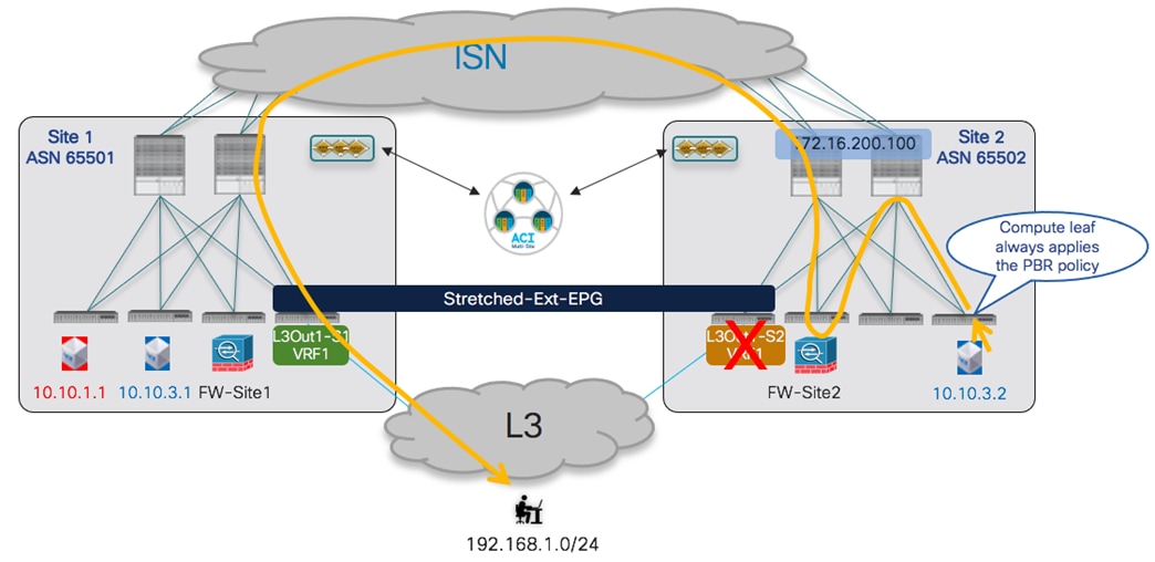
Intersite L3Out and Service Graph with PBR
Firewall Insertion for North-South Traffic Flows (Inter-VRFs)
Starting from ACI release 4.2(5) and 5.1(1), service insertion for north-south traffic flow is supported also for the inter-VRF use case where the L3Out and the internal EPGs are mapped to different VRFs (that can be deployed in the same tenant or in different tenants). The functional behavior in this case is the same already shown previous Figure 133 and Figure 135 for the intra-VRF scenario. Also, in this case, the PBR policy is always applied to the compute leaf nodes to avoid the creation of asymmetric traffic across the independent service node functions deployed in separate ACI fabrics.
From a provisioning perspective, the following specific considerations apply in the inter-VRFs use case:
● The internal consumer BD subnets and Ext-EPG prefixes must be properly configured to ensure route-leaking happens and the BD subnets are advertised toward the external network. For more configuration information on how to achieve this, please refer to the previous “Connectivity to the External Layer 3 Domain” section.
● For intra-tenant deployments, the “Service-BD” can be configured as part of either VRFs, as long as it is a stretched object. For inter-tenant scenarios, the “Service-BD” must instead be part to the VRF defined in the provider Tenant.
● The contract with the associated service graph must have a scope of “Tenant” (if the VRFs are part of the same tenant) or “Global” (if the VRFs are part of different tenants). In the inter-tenant scenario, the contract must be defined in a template (usually a stretched template) associated with the provider Tenant.
● For ensuring that the application of the PBR policy is always happening on the compute leaf nodes, the Ext-EPG is always defined as the provider of the contract whereas the internal EPGs are the consumer.
Once the provisioning steps above are completed, the north-south traffic flows would behave exactly like in the intra-VRF use case. This applies also to the scenario where the service graph is combined with intersite L3Out, similarly to what shown in Figure 142 for the intra-VRF case.
From a verification perspective, the first thing to check is that the routes are properly leaked between the VRFs, The output below shows the specific example where the external prefix 192.168.1.0/24 is leaked into VRF1 on the compute leaf node, whereas the subnet for BD1-S1 (10.10.1.0/24) is leaked into VRF-Shared on the border leaf node.
Leaf 101 Site1
Leaf101-Site1# show ip route vrf Tenant-1:VRF1
IP Route Table for VRF "Tenant-1:VRF1"
'*' denotes best ucast next-hop
'**' denotes best mcast next-hop
'[x/y]' denotes [preference/metric]
'%<string>' in via output denotes VRF <string>
10.10.1.0/24, ubest/mbest: 1/0, attached, direct, pervasive
*via 10.1.112.66%overlay-1, [1/0], 12:48:25, static
10.10.1.254/32, ubest/mbest: 1/0, attached, pervasive
*via 10.10.1.254, vlan57, [0/0], 00:29:17, local, local
192.168.1.0/24, ubest/mbest: 1/0
*via 10.1.0.69%overlay-1, [200/0], 01:18:33, bgp-65501, internal, tag 3, rwVnid: vxlan-2293765
Leaf 104 Site1
Leaf104-Site1# show ip route vrf Tenant-1:VRF-Shared
IP Route Table for VRF "Tenant-1:VRF-Shared"
'*' denotes best ucast next-hop
'**' denotes best mcast next-hop
'[x/y]' denotes [preference/metric]
'%<string>' in via output denotes VRF <string>
10.10.1.0/24, ubest/mbest: 1/0, attached, direct, pervasive
*via 10.1.112.66%overlay-1, [1/0], 00:31:30, static, tag 4294967292, rwVnid: vxlan-3112963
192.168.1.0/24, ubest/mbest: 1/0
*via 172.16.1.1%Tenant-1:VRF-Shared, [20/0], 21:11:40, bgp-65501, external, tag 3
Notice how associated to the leaked prefixes is the info of the specific Segment ID to insert in the VXLAN header when sending the traffic to the other leaf node (vxlan-2293765 is assigned to VRF-Shared, whereas vxlan-3112963 is assigned to VRF1). This ensures that the receiving leaf node can perform the Layer 3 lookup in the right VRF.
From a security policy perspective, traffic received on the BL node from the external network is associated with the Ext-EPG (based on matching the prefix configured for classification under the Ext-EPG) and assigned a corresponding class-ID (5493 in the specific example below). Internal endpoints part of the consumer VRF are instead classified with a “special” Class-ID value 14 so that the rule installed in the HW ensures that the inbound flow is forwarded into the fabric.
Leaf 104 Site1
Leaf104-Site1# show zoning-rule scope 2293765
+---------+--------+--------+----------+---------+---------+---------+------+-----------------+----------------------+
| Rule ID | SrcEPG | DstEPG | FilterID | Dir | operSt | Scope | Name | Action | Priority |
+---------+--------+--------+----------+---------+---------+---------+------+-----------------+----------------------+
| 4217 | 0 | 0 | implicit | uni-dir | enabled | 2293765 | | deny,log | any_any_any(21) |
| 4181 | 0 | 0 | implarp | uni-dir | enabled | 2293765 | | permit | any_any_filter(17) |
| 4233 | 0 | 15 | implicit | uni-dir | enabled | 2293765 | | deny,log | any_vrf_any_deny(22) |
| 4153 | 5493 | 14 | implicit | uni-dir | enabled | 2293765 | | permit_override | src_dst_any(9) |
| 4203 | 0 | 16390 | implicit | uni-dir | enabled | 2293765 | | permit | any_dest_any(16) |
| 4242 | 29 | 5493 | default | uni-dir | enabled | 2293765 | | permit | src_dst_any(9) |
| 4207 | 29 | 14 | implicit | uni-dir | enabled | 2293765 | | permit_override | src_dst_any(9) |
+---------+--------+--------+----------+---------+---------+---------+------+-----------------+----------------------+
Once the traffic gets to the compute leaf, the PBR policy kicks in and causes the redirection of traffic to the service node. This is highlighted in the line below (source class-ID 5493, destination class-ID 16391 that represents EPG1-S1). Notice also the presence of the redirection rule for the reverse traffic originated from EPG1-S1 and destined to the external network domain.
Leaf 101 Site1
Leaf101-Site1# show zoning-rule scope 3112963
+---------+--------+--------+----------+----------------+---------+---------+------+------------------+------------------------+
| Rule ID | SrcEPG | DstEPG | FilterID | Dir | operSt | Scope | Name | Action | Priority |
+---------+--------+--------+----------+----------------+---------+---------+------+------------------+------------------------+
| 4194 | 0 | 0 | implicit | uni-dir | enabled | 3112963 | | deny,log | any_any_any(21) |
| 4203 | 0 | 0 | implarp | uni-dir | enabled | 3112963 | | permit | any_any_filter(17) |
| 4227 | 0 | 15 | implicit | uni-dir | enabled | 3112963 | | deny,log | any_vrf_any_deny(22) |
| 4180 | 5493 | 16391 | default | uni-dir-ignore | enabled | 3112963 | | redir(destgrp-5) | src_dst_any(9) |
| 4235 | 16391 | 5493 | default | bi-dir | enabled | 3112963 | | redir(destgrp-5) | src_dst_any(9) |
+---------+--------+--------+----------+----------------+---------+---------+------+------------------+------------------------+
It is worth noticing that the compute leaf can derive the right class-ID for traffic destined to the external destination 192.168.1.0/24, based on the fact that this information is programmed on the compute leaf node as a result of the setting of the “Shared Security Import” flag associated to the subnet configured under the Ext-EPG. This information can be retrieved using the command below:
Leaf 101 Site1
Leaf101-Site1# vsh -c 'show system internal policy-mgr prefix'
Requested prefix data
Vrf-Vni VRF-Id Table-Id Table-State VRF-Name Addr Class Shared Remote Complete
======= ====== =========== ======= ============================ ================================= ====== ====== ====== ========
3112963 42 0x2a Up Tenant-1:VRF1 192.168.1.0/24 5493 True True False
Firewall Insertion for East-West Traffic Flows (Intra-VRF)
When the service node must be inserted for intra-VRF communication between two internal EPGs (also referred to as “east-west” use case), a different mechanism than the one used for north-south (i.e. always applying the PBR policy on the compute leaf node) must be used to avoid the creation of asymmetric traffic across independent service nodes.
In the current implementation, it is leveraging the fact that every contract relationship between EPGs always defines a “consumer” and a “provider” side. Starting from ACI release 4.0(1), the application of the PBR policy is hence anchored always on the compute leaf where the provider endpoint is connected, usually referred to as the “provider leaf”.
Figure 143 shows the PBR policy in action when the communication is initiated from the consumer endpoint, which represents the most common scenario. The traffic is forwarded by Multi-Site to the provider leaf, where the PBR policy is applied redirecting the traffic to the service node. Once the service node has applied the policy, the traffic is then delivered to the provider endpoint.
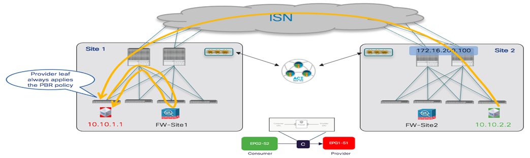
PBR for Communication between Consumer and Provider EPGs
As a result of the communication flow above, the specific consumer endpoint information is learned on the provider leaf node. This implies that when the provider endpoint replies, the PBR policy can be applied again on the provider leaf, allowing to redirect the traffic to the same service node that handled the first leg of the communication (Figure 144). Once the service node has applied the policy, the traffic can then be forwarded across the ISN toward the consumer endpoint.
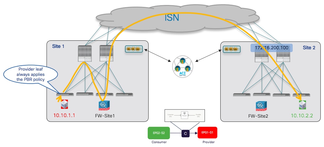
PBR for Communication between Provider and Consumer EPGs
The conclusion that can be drawn from the figures above is that for every east-west communication between endpoints connected to the fabrics, the traffic is always going to be redirected to the service node in the site where the provider endpoint is located.
It is critical to ensure that it is always possible to identify a consumer and a provider side in zoning rules for each given contract relationship between EPGs. This means that the same EPG should never consume and provide the same contract and the definition of different contracts may be needed depending on the specific deployment scenario.
Also, if two different contracts were applied between the same pair of EPGs (as to be able to differentiate the provider and consumer EPG for each of them), it is critical to ensure that the zoning rules created by those two contracts don’t have overlapping rules with same contract and filter priorities. Defining zoning rules with the same priority that identify the same type of traffic could lead to a not deterministic forwarding behavior (creating asymmetric traffic through different firewalls).
As a typical example, it would not work to create two contracts both using a “permit any” rule to redirect all the traffic. If one contract is “permit any” and the other contract is “permit ICMP only”, the zoning-rules created by the contract with “permit ICMP only” would have higher priority.
One last important consideration: we need to ensure that the PBR policy can be applied on the provider leaf even in the specific scenario where the communication may be initiated by the provider endpoint. In such scenario, there may not be yet consumer endpoint information available on the provider leaf (learned via data-plane communication, as explained above), so a different mechanism is required to derive the destination class-ID of the consumer EPG and apply the policy. In the current implementation this is achieved based on a “static” approach consisting in configuring a subnet prefix under the consumer EPG. This information is then propagated from NDO to the APIC domain on the provider site and allows APIC to install that prefix on the provider leaf node, with the associated class-ID identifying the consumer EPG.
It is hence critical to ensure that the prefix configured under the consumer EPG includes all the IP addresses of the endpoints part of that EPG. In a “network-centric” ACI deployment (where a single EPG is defined in a BD), this is easily achievable by associating to the EPG the same IP subnet configured for the BD. In “application-centric” use cases, where multiple EPGs may be defined under the same BD, it may become much more challenging being able to identify a prefix including only the endpoints connected to a specific EPG and the only solution may be to use specific /32 prefixes for every endpoint that is connected to the EPG. This last approach does not represent a viable option in real-life deployments, so the use of service-graph with PBR for east-west communication is usually recommended and restricted only to “network-centric” configurations.
For what concerns the provisioning of the configuration required for achieving the behavior described above, the assumption is that the tenant EPGs/BDs are already deployed, and endpoints are connected to them (EPGs can either be locally defined in each site or stretched across sites). Also, the logical firewall service nodes and PBR policies have been deployed in each site, as described in the “Service Graph with PBR with Multi-Site for the Insertion of a Single Service Node” section. Once those pre-requisite steps are done, it is possible to follow pretty much identically the steps already described as part of the “Firewall Insertion for North-South Traffic Flows (Intra-VRF)”:
● Define a stretched service BD where the firewall nodes should be connected.
● Create the service graph (also as a stretched object). Notice that the same service graph used for north-south communication could also be used for east-west traffic flows.
● Create a contract (with scope VRF) and associate the service graph to it.
● Specify a prefix under the consumer EPG allowing to match the IP addresses of all the consumer endpoints that are part of the EPG. The same flags used for the subnet under the BD should be configured for this prefix, with the addition of the “No Default SVI Gateway” flag.
Apply the contract between the consumer and provider EPGs.
Once the contract is applied, east-west communication is successfully established with proper redirection to the service node.
Looking at the endpoint table on the provider leaf, it is possible to verify how the consumer endpoint is indeed learned. The consumer endpoint is remotely located, hence reachable via a VXLAN tunnel (tunnel26) established between the provider leaf and the O-UTEP address of the spines in the remote site.
Leaf 101 Site1
Leaf101-Site1# show endpoint vrf Tenant-1:VRF1
Legend:
s - arp H - vtep V - vpc-attached p - peer-aged
R - peer-attached-rl B - bounce S - static M - span
D - bounce-to-proxy O - peer-attached a - local-aged m - svc-mgr
L - local E - shared-service
+-----------------------------------+---------------+-----------------+--------------+-------------+
VLAN/ Encap MAC Address MAC Info/ Interface
Domain VLAN IP Address IP Info
+-----------------------------------+---------------+-----------------+--------------+-------------+
Tenant-1:VRF1 10.10.2.2 tunnel26
60 vlan-819 0050.56b9.1bee LV po1
Tenant-1:VRF1 vlan-819 10.10.1.1 LV po1
As a result of the prefix configuration under the consumer EPG, the prefix is installed on the provider leaf with the associated class-ID (49163).
Leaf 101 Site1
Leaf101-Site1# cat /mit/sys/ipv4/inst/dom-Tenant-1:VRF1/rt-\[10.10.2.0--24\]/summary
# IPv4 Static Route
prefix : 10.10.2.0/24
childAction :
ctrl : pervasive
descr :
dn : sys/ipv4/inst/dom-Tenant-1:VRF1/rt-[10.10.2.0/24]
flushCount : 0
lcOwn : local
modTs : 2020-12-16T13:27:29.275+00:00
monPolDn :
name :
nameAlias :
pcTag : 49163
pref : 1
rn : rt-[10.10.2.0/24]
sharedConsCount : 0
status :
tag : 0
trackId : 0
This ensures that the PBR policy can always be applied on the provider leaf, even in cases where the specific consumer endpoint information is not yet learned. In the output below, 16388 is the class-ID for the local provider EPG1-S1, so it is possible to see how redirection to the service node is applied for both directions of the traffic (consumer to provider and vice versa).
Leaf 101 Site1
Leaf101-Site1# show zoning-rule scope 3112963
+---------+--------+--------+----------+----------------+---------+---------+------+------------------+----------------------+
| Rule ID | SrcEPG | DstEPG | FilterID | Dir | operSt | Scope | Name | Action | Priority |
+---------+--------+--------+----------+----------------+---------+---------+------+------------------+----------------------+
| 4194 | 0 | 0 | implicit | uni-dir | enabled | 3112963 | | deny,log | any_any_any(21) |
| 4203 | 0 | 0 | implarp | uni-dir | enabled | 3112963 | | permit | any_any_filter(17) |
| 4227 | 0 | 15 | implicit | uni-dir | enabled | 3112963 | | deny,log | any_vrf_any_deny(22) |
| 4197 | 0 | 49153 | implicit | uni-dir | enabled | 3112963 | | permit | any_dest_any(16) |
| 4138 | 0 | 16393 | implicit | uni-dir | enabled | 3112963 | | permit | any_dest_any(16) |
| 4217 | 0 | 32771 | implicit | uni-dir | enabled | 3112963 | | permit | any_dest_any(16) |
| 4222 | 0 | 49162 | implicit | uni-dir | enabled | 3112963 | | permit | any_dest_any(16) |
| 4230 | 49163 | 16388 | default | bi-dir | enabled | 3112963 | | redir(destgrp-6) | src_dst_any(9) |
| 4170 | 16388 | 49163 | default | uni-dir-ignore | enabled | 3112963 | | redir(destgrp-6) | src_dst_any(9) |
| 4202 | 16394 | 16388 | default | uni-dir | enabled | 3112963 | | permit | src_dst_any(9) |
| 4174 | 16394 | 49163 | default | uni-dir | enabled | 3112963 | | permit | src_dst_any(9) |
+---------+--------+--------+----------+----------------+---------+---------+------+------------------+----------------------+
Firewall Insertion for East-West Traffic Flows (Inter-VRFs)
The service node integration for east-west communication between EPGs that are part of different VRFs works essentially like the intra-VRF scenario just discussed. The PBR policy is always applied on the provider leaf node and the only specific considerations for this scenario in terms of provisioning are detailed below.
● Enable the “Shared between VRFs” flag for both the consumer and provider BDs.
● Ensure that the same flag is also configured for the prefix configured under the consumer EPG (Nexus Dashboard Orchestrator would prevent to deploying the configuration if that was not the case).
● To leak the BD subnet from the provider to the consumer VRF, the subnet prefix associated to the provider BD must also be configured under the provider EPG.
Note: The same considerations around “network-centric” and “application-centric” deployments apply also when configuring the prefix under the provider EPG to trigger the route leaking functionality.
● The scope of the contract with the associated service graph should be changed to “Tenant” (if the VRFs are deployed in the same Tenant) or to “Global” (if the VRFs are deployed in different Tenants).
● For inter-tenant deployments, the service BD, the service graph and the contract should all be deployed as part of the provider Tenant.
As it was the case for intra-VRF, also in the inter-VRFs east-west service-graph the application of the PBR policy is possible thanks to the configuration of the prefix under the consumer EPG that triggers the provisioning of that prefix, and the associated class-ID, on the provider leaf node:
Leaf 101 Site1
Leaf101-Site1# cat /mit/sys/ipv4/inst/dom-Tenant-1:VRF-Shared/rt-\[10.10.2.0--24\]/summary
# IPv4 Static Route
prefix : 10.10.2.0/24
childAction :
ctrl : pervasive
descr :
dn : sys/ipv4/inst/dom-Tenant-1:VRF-Shared/rt-[10.10.2.0/24]
flushCount : 1
lcOwn : local
modTs : 2020-12-16T14:30:51.006+00:00
monPolDn :
name :
nameAlias :
pcTag : 10936
pref : 1
rn : rt-[10.10.2.0/24]
sharedConsCount : 0
status :
tag : 4294967292
trackId : 0
It is worth noticing how the consumer prefix is now assigned a class-ID value (10936) taken from the global range that is unique across all the VRFs. The same applies to the class-ID for the provider EPG, which now gets the value of 32 as shown in the output below pointing out the rules used to redirect the traffic flows to the service node.
Leaf 101 Site1
Leaf101-Site1# show zoning-rule scope 2293765
+---------+--------+--------+----------+----------------+---------+---------+------+------------------+----------------------+
| Rule ID | SrcEPG | DstEPG | FilterID | Dir | operSt | Scope | Name | Action | Priority |
+---------+--------+--------+----------+----------------+---------+---------+------+------------------+----------------------+
| 4230 | 0 | 0 | implicit | uni-dir | enabled | 2293765 | | deny,log | any_any_any(21) |
| 4200 | 0 | 0 | implarp | uni-dir | enabled | 2293765 | | permit | any_any_filter(17) |
| 4234 | 0 | 15 | implicit | uni-dir | enabled | 2293765 | | deny,log | any_vrf_any_deny(22) |
| 4222 | 10936 | 32 | default | bi-dir | enabled | 2293765 | | redir(destgrp-6) | src_dst_any(9) |
| 4191 | 32 | 10936 | default | uni-dir-ignore | enabled | 2293765 | | redir(destgrp-6) | src_dst_any(9) |
| 4236 | 0 | 49154 | implicit | uni-dir | enabled | 2293765 | | permit | any_dest_any(16) |
+---------+--------+--------+----------+----------------+---------+---------+------+------------------+----------------------+
Service Graph with PBR with Multi-Site for the Insertion of Two (or more) Service Nodes
The use of service graph and PBR allows also to chain together two (or more) service node functions so that communication between endpoints part of two EPGs can allow only after the traffic is gone through the operation performed by each service node. This can apply to north-south and east-west traffic flows, as highlighted in Figure 145.
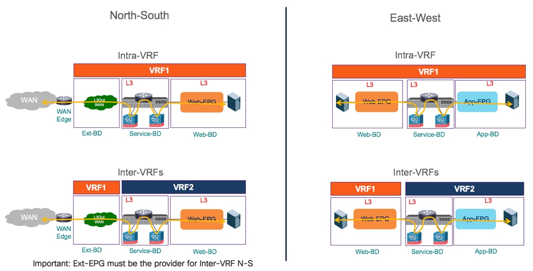
Two Nodes Service Graph with PBR
The provisioning of a multi-node service-graph function with PBR is similar to what was previously discussed for a single node use case. The first step consists in defining the multiple service node logical functions that should be offered by each fabric part of the Multi-Site domain. Figure 146 shows the creation of two logical L4/L7 devices performed at the APIC level. Each logical device will then be implemented with one, two, or more concrete service nodes, depending on the specific deployment/redundancy model of choice, as shown in previous Figure 128.
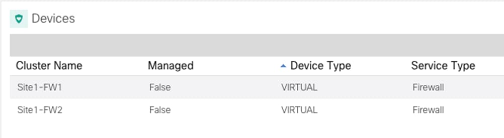
Definition of two Logical Firewall Nodes on the APIC of Site1
The second provisioning step performed on APIC consists in defining the PBR policies allowing to redirect the traffic through the service nodes. Since we have defined two service nodes, it is hence required to define two separate PBR policies as well. As shown in Figure 147, each policy redirects traffic to a specific MAC/IP pair, identifying each specific service node function.
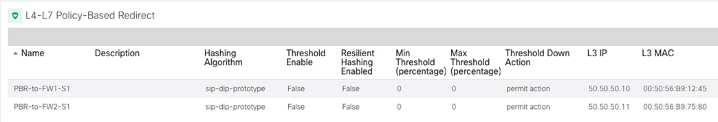
PBR Policies for a Two Service nodes Redirection
Note: A similar configuration must be performed for all the fabrics part of the Multi-Site domain.
At this point, it is possible to provide the specific configuration allowing to stitch the two service nodes in the middle of communications between EPGs for both north-south and east-west traffic flows
As for the single service node use case, the PBR policy for north-south communication must always be applied on the compute leaf nodes. This is always the case for intra-VRF use cases as long as the VRF remains configured with the default ingress policy enforcement direction; in the inter-VRF scenario, it is instead mandatory to ensure that the Ext-EPG is always configured as the provider of the contract that has associated the service graph.
Nodes Insertion for North-South Traffic Flows
Figure 148 highlights how the PBR redirection for north-south flows always ensures that the service nodes that are utilized are the ones located in the same site with the internal endpoint.
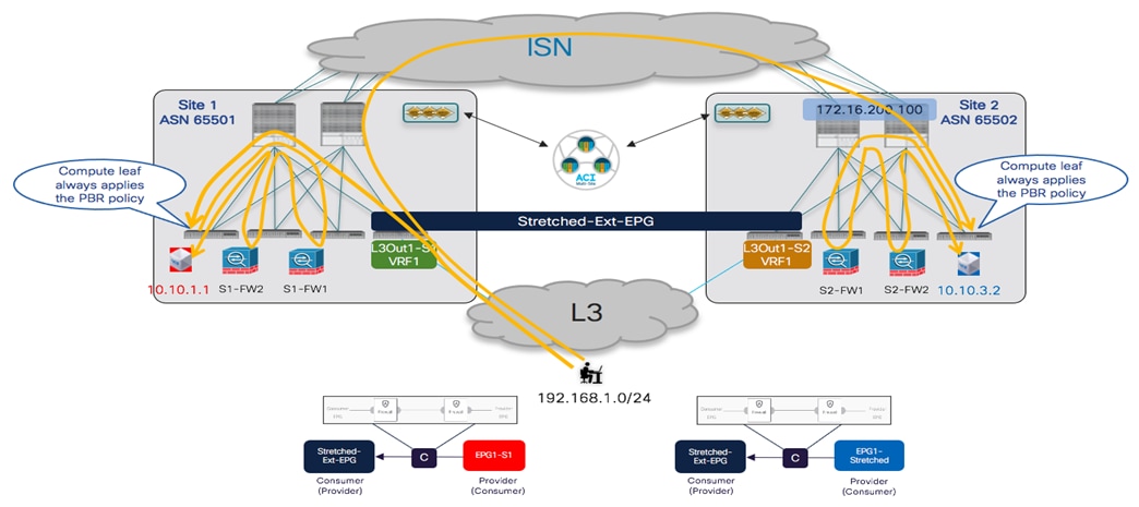
PBR Redirection for North-South Traffic Flows
The provisioning steps to be performed on NDO to integrate the firewall for north-south traffic flows (intra-VRF) are described below.
● Configure the subnet of the consumer and provider BDs to ensure they can be advertised out of the L3Out in each site. This requires configuring the BD subnets as “Advertised Externally” and to map the BDs to the specific L3Outs where the prefix should be advertised, as described in the previous “Connectivity to the External Layer 3 Domain” section.
● Configure the External EPG to properly classify incoming traffic. Assuming a stretched Ext-EPG is deployed, it is common to specify a “catch-all” 0.0.0.0/0 prefix with the associated “External Subnets for External EPGs” flag set.
● Define the “service BD” used to connect the firewall nodes deployed in each fabric. This BD must be provisioned from the Nexus Dashboard Orchestrator in a template associated with all the sites. The Service-BD is provisioned identically as shown in Figure 136 for the single service node insertion use case.
● Create the service graph on the Orchestrator for the insertion of the two service nodes: this should also be done on the template associated to all the sites part of the Multi-Site domain (i.e. the service graph is provisioned as a ‘stretched’ object). As shown in Figure 149, the configuration for the service graph is provisioned in two parts: first, at the global template level to specify which service nodes should be inserted (two firewalls in this specific example). Second, at the site level to map the specific the logic firewall devices that have been defined on APIC and are now exposed to Nexus Dashboard Orchestrator (see previous Figure 146).
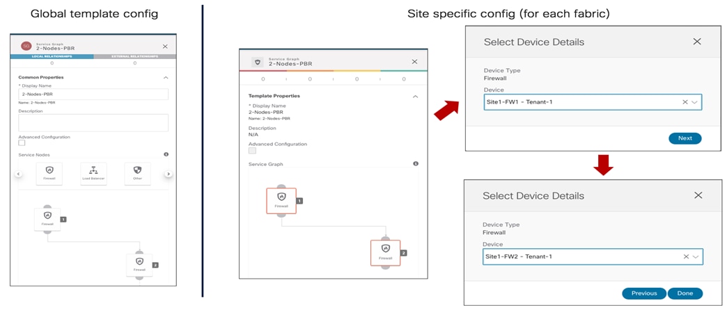
Definition of the Two-Nodes Service Graph on NDO
● Define a contract and associate to it the service graph. The contract is usually defined in a template associated with all the sites and in the example in Figure 150, a “Permit-All” filter is associated with the contract to ensure that all traffic is redirected to the firewall. It is possible to change this behavior and make the filter more specific if the goal is instead to redirect to the firewall only specific traffic flows.
As shown in the following two figures, once the service graph is associated with the contract, it is then required to perform a two steps configuration: at the global template level, we need to specify the BD where the firewall logical nodes are connected (Figure 150). In our specific example, the firewalls are connected in one-arm mode, hence it is possible to specify the same “Service-BD” for both consumer and provider firewall connectors (interfaces). Notice also that the “Service-BD” must be associated with the connectors at the global template level, which is the main reason why that BD must be provisioned as a stretched object in all the sites.
Also, at the site level, it is required instead to associate the PBR policy to each service node (Figure 151). The redirection policy is associated with each interface of the service node (consumer and provider connectors). In our specific example where the service nodes are connected in one-arm mode, the same PBR policy is applied for each connector, but that would not for example be the case when the firewall is connected in two-arms mode. Also, in specific service-graph deployments, there may be needed to apply the PBR policy only for one interface (i.e., for one specific direction of traffic)
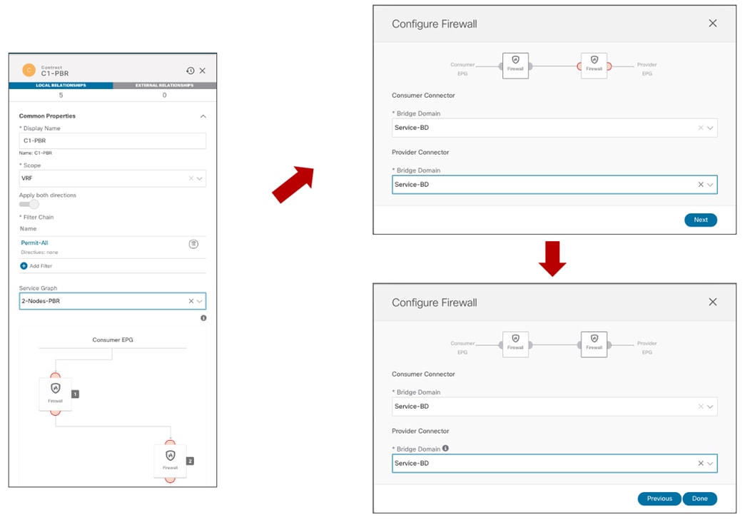
Definition of the Contract with Associated Service Graph (Global Template Level)
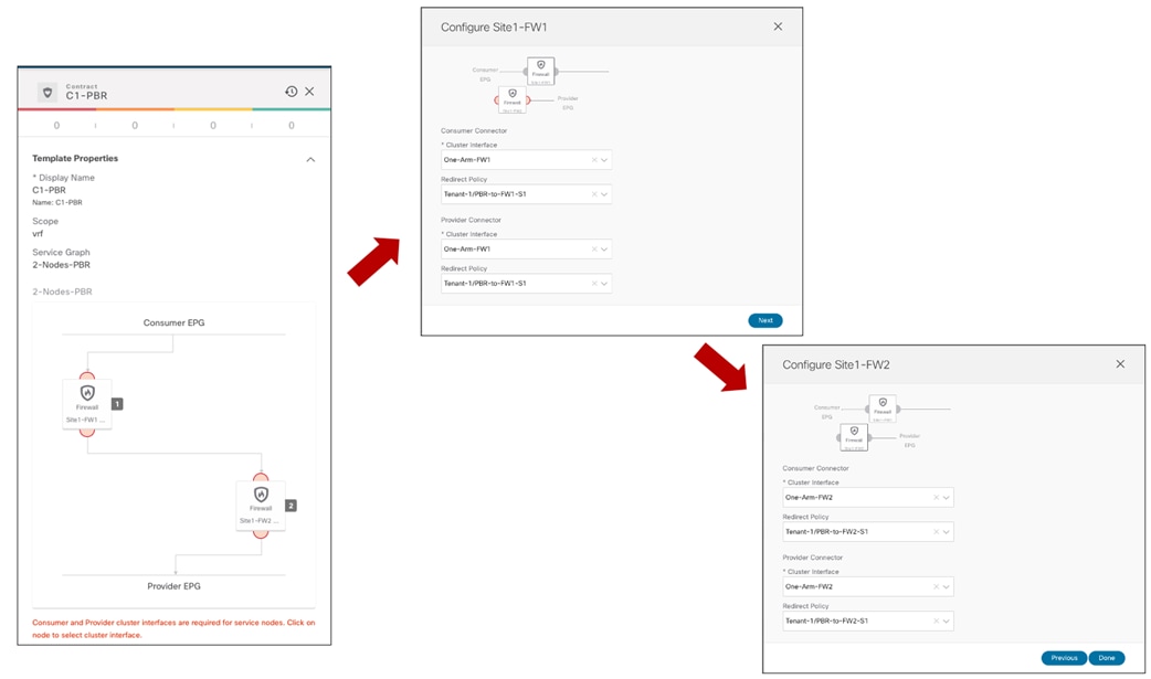
Association of the PBR Policy to Each Service Node Interface (Site Local Level)
● The last provisioning step consists in applying the previously defined contract between the internal EPGs and the external EPG. As previously discussed in the “Connectivity to the External Layer 3 Domain” section, the definition of a stretched external EPG is recommended for the L3Outs deployed across sites that provide access to the same set of external resources, as it simplifies the application of the security policy.

Applying the Contract to Consumer and Provider EPGs
In the infra-VRF scenario discussed in this section, it does not matter which side is the provider or the consumer, the PBR policy is always applied on the compute leaf node anyway.
Note: As of NDO release 3.5(1), vzAny cannot be used in conjunction with a contract that has associated a service graph. The only option to apply a PBR policy between two EPGs (internal and/or external) consists hence in creating a specific contract, as in the example above.
Once the provisioning steps described above are completed, a separate service graph is deployed in each APIC domain and north-south traffic flows start getting redirected through the firewall nodes. Please refer to the “Firewall Insertion for North-South Traffic Flows (Intra-VRF)” for more information on how to verify the correct behavior of the redirection.
Very similar provisioning steps are needed for the inter-VRF (and/or inter-tenant) use case. You can find more info on how to deploy this scenario in the previous “Firewall Insertion for North-South Traffic Flows (Inter-VRFs)” section.
Two Service Nodes Insertion for East-West Traffic Flows
The same two nodes service graph provisioned for the north-south use case can also be re-utilized for the east-west scenario shown in Figure 153 and Figure 154.
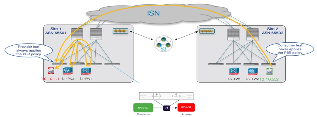
2-Nodes PBR for Communication between Consumer and Provider EPGs
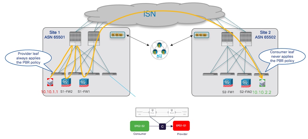
2-Nodes PBR for Communication between Provider and Consumer EPGs
The same considerations discussed in the “Firewall Insertion for East-West Traffic Flows (Intra-VRF)” and “Firewall Insertion for East-West Traffic Flows (Inter-VRFs)” sections continue to apply also for the 2-nodes scenario. This means that the only additional configuration step that is required to “anchor” the application of the PBR policy on the provider leaf node consists in configuring the prefix under the consumer EPG.
Integrating ACI Multi-Pod and ACI Multi-Site
In many real-life deployment scenarios, customers have the need to integrate the ACI Multi-Pod and Multi-Site architecture to be able to tackle the specific requirements that can be satisfied by deploying tightly coupled ACI DCs (Multi-Pod) with loosely coupled ACI DCs (Multi-Site).
Figure 155 below shows an example of a topology where an ACI Multi-Pod fabric and a single Pod ACI fabric are deployed as part of the same Multi-Site domain.
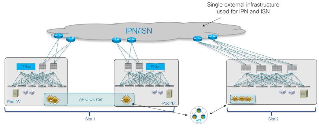
Integration between ACI Multi-Pod and ACI Multi-Site
More details about the specific deployment considerations to integrate those architecture can be found in the CI Multi-Site white paper. The next two sections highlight what are the required configuration steps to deploy the architecture shown above, taking into consideration two specific use cases:
● Adding a Multi-Pod fabric and single Pod Fabric to the same Multi-Site domain.
● Converting a single Pod fabric (already part of a Multi-Site domain) to a Multi-Pod fabric.
Adding a Multi-Pod fabric and single Pod Fabric to the same Multi-Site domain
This use case is typical of a scenario where a Multi-Pod fabric has already been deployed to bundle together as part of the same “logical DC” different ACI islands (representing rooms, halls, buildings ot even specific DC locations) and it is then required to add it to the same Multi-Site domain with a separate single Pod fabric (representing for example a Disaster Recovery site).
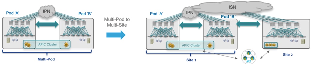
Adding a Multi-Pod fabric and single Pod Fabric to the same Multi-Site domain
The initial assumptions are the following:
● The Multi-Pod fabric is already up and running, so that the spine nodes in different Pods are peering EVPN across an IPN infrastructure interconnecting the Pods (i.e., the required L3Out in the “infra” tenant has already been created, either manually or by leveraging the APIC Multi-Pod wizard).
Note: For more details on how to bring up a Multi-Pod fabric, please refer to the configuration document below:
● The NDO 3.5(1) service has been enabled on the Nexus Dashboard compute cluster.
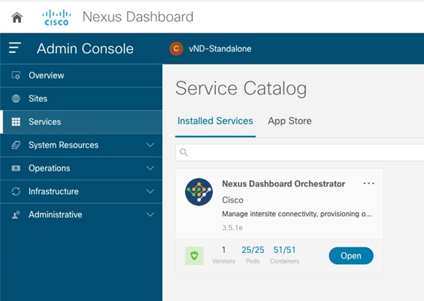
NDO Service Enabled on Nexus Dashboard
Note: The use of a vND standalone node shown above is only supported for lab or Proof oc Concept (PoC) activities and not for real life production deployments.
· The ACI Multi-Pod fabric has been onboarded to the Nexus Dashboard platform.
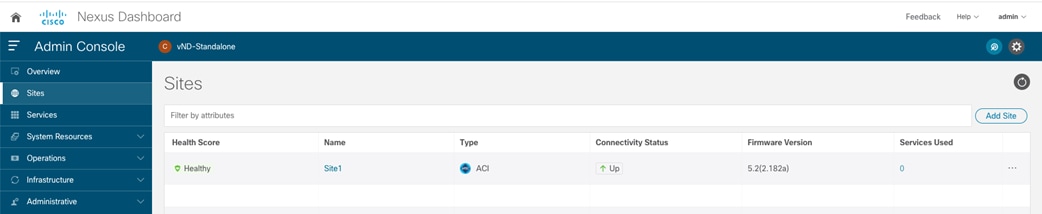
Site1 (ACI Multi-Pod Fabric) Onboarded on Nexus Dashboard
The first step to add the ACI Multi-Pod fabric to the Multi-Site domain consists in setting the state of the fabric as “Managed” on the Nexus Dashboard Orchestrator UI and assigning it a unique Site ID.

Set the Fabric State to “Managed” and Assign It a Unique Site ID
At this point, it is possible to access the “Configure Infra” section to start the required provisioning to add the fabric to the Multi-Site domain (as shown in the inital section “Nexus Dashboard Orchestrator Sites Infra Configuration”. You will notice several differences compared to the scenario of adding a new single Pod fabric, due to the fact that an L3Out part of the Infra Tenant already exists on APIC (as it was created during the provisioning of the Multi-Pod fabric) and that same L3Out must be used also for Multi-Site. Hence, NDO takes ownership of the Infra L3Out and automatically imports several configuration parameters from APIC, leaving to the user only the responsibility of configuring the remaining items:
● Site level configuration as shown in the figure below, the BGP and OSPF related fields are automatically provisioned based on the information retrieved from the Infra L3Out on APIC. The only configuration required at the site level consists in enabling the “ACI Multi-Site” knob and specify the “Overlay Multicast TEP” address used to receive L2 BUM and L3 Multicast traffic. As mentioned at the beginning of this paper, for the O-MTEP you should provision an IP address that is routable across the ISN infrastructure connecting the ACI fabrics.
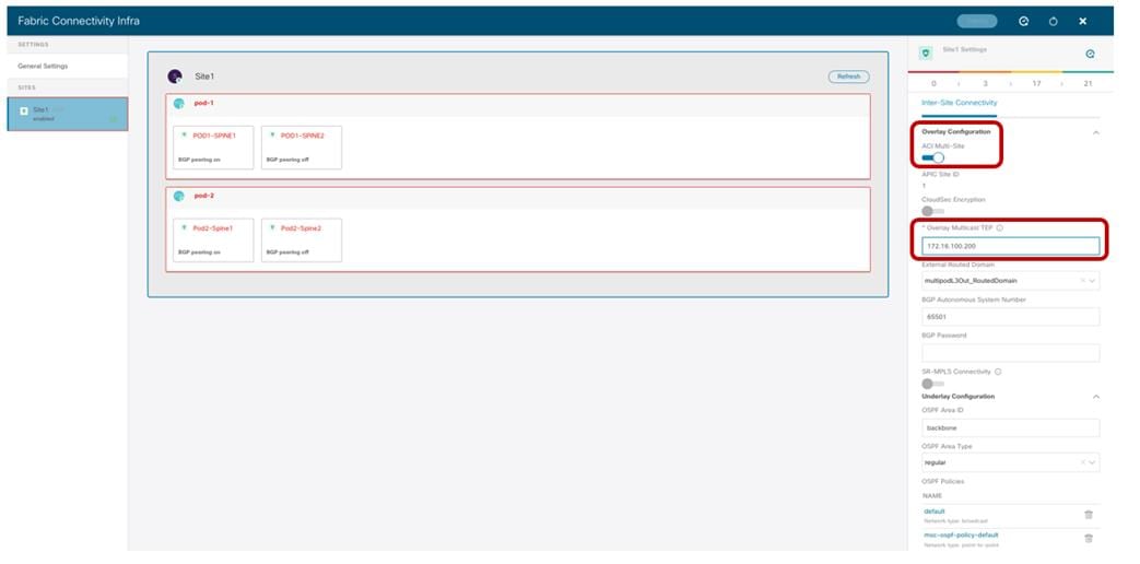
Fabric Level Configuration
● Pod Level Configuration: the only parameter that needs to be provisioned for each Pod is the Overlay Unicast TEP address, used to send and receive intersite VXLAN traffic for unicast Layer 2 and Layer 3 communication.
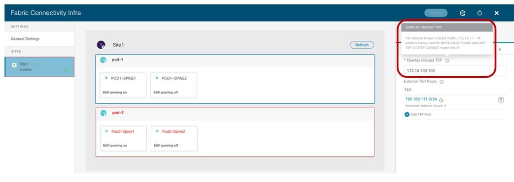
Pod Level Configuration
As described by the information shown when hovering with the mouse over the “i” icon, the provisioned O-UTEP address must be different from the Data Plane TEP address that was configured on APIC during the ACI Multi-Pod fabric configuration (172.16.1.1). As it is the case for the O-MTEP address, also the O-UTEP address must be routable across the ISN to ensure that the VXLAN data plane communication between sites can be successfully established.
Note: In case Remote-Leaf nodes were added to the Multi-Pod fabric, a separate Anycast TEP address would have also been assigned to the spines of each Pod for establishing VXLAN communication between each Pod and the RL nodes: the O-UTEP used in each Pod for Multi-Site must also be different from the Anycast TEP address used for RL deployment.
As noticed in figure 160 above, External TEP Pools already defined on APIC will also be automatically inherited by NDO (192.168.111.0/24 in this specific example). As described in the “Deploying Intersite L3Out” section, the use of External TEP Pools is required to enable Intersite L3Out communication.
● Spine Level Configuration: for each spine, the interfaces part of the infra L3Out (and used for Multi-Pod) are automatically retrieved from APIC and shown (interfaces 1/63 and 1/64 in the example below). The only required configuration is enabling BGP on the subset of spines that need to function as BGP Speakers (i.e., creating BGP EVPN adjacencies with the BGP speakers in remote sites) and specify the BGP-EVPN Router-ID representing the IP address of the loopback interfaces used to establish those remote adjacencies. As shown below, it is possible in this case to re-use the same address that was already assigned to the spine for establishing the EVPN adjacencies between Pods required by Multi-Pod.

Spine Level Configuration
It is recommended to deploy a pair of BGP speakers per fabric to provide redundant EVPN adjacencies with the remote sites. If the fabric is Multi-Pod, one spine in two separate Pods should be provisioned as Speaker (Pod1-Spine 1 and Pod2-Spine1 in the specific example above). The spines that are not Speakers become Forwarders by default and establish only EVPN peerings with the local Speakers. For more information on the role of BGP speakers and forwarders and how control and data planes work when integrating Multi-Pod and Multi-Site, please refer to the ACI Multi-Site paper below:
Once the Multi-Pod fabric is successfully added to the Multi-Site domain, it is then possible to add the single Pod fabric that in our example represents the DR site. How to achieve this task has already been covered as part of the “Adding the ACI Fabrics to the Multi-Site Domain” section.
Converting a single Pod fabric (already part of a Multi-Site domain) to a Multi-Pod fabric
This second scenario is simpler, since the starting point is the one where two single-Pod fabrics are already added as part of the Multi-Site domain. The goal is then to expand one of the two fabrics by adding a second Pod.
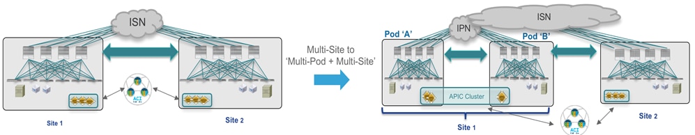
Converting a single Pod fabric (already part of a Multi-Site domain) to a Multi-Pod fabric
Figure 164 below highlights the two single-Pod fabrics initially part of the Multi-Site domain. As noticed, both spines in each Pod are deployed as BGP speakers (“BGP peering on”) for the sake of fabric-level resiliency.
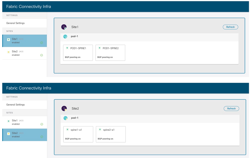
Two Single-Pod Fabrics Part of the Multi-Site Domain
The first step consists in running the ACI Multi-Pod wizard on APIC for Site1 to add a second Pod and build a Multi-Pod fabric. Detailed information on how to build a Multi-Pod fabric can be found in the paper below:
Important Note
Please be aware of a specific software defect impacting this specific use case (CSCvu76783). The issue happens only when running the Multi-Pod wizard on APIC to add a second Pod to a fabric that is already part of a Multi-Site domain. Given the presence of the infra L3Out created for Multi-Site, the Multi-Pod wizard skips completing some specific settings for the nodes in Pod-1. When running pre-5.2(1) ACI code, a possible workaround consists in manually setting the parameters below once the Multi-Pod wizard is completed:
1. Under tn-infra > networking > L3Outs > "intersite" > Logical Node Profile > “Profile" > Configured Nodes > each spine "Node" is missing 2 items. One, the checkbox "Use Router as loopback address" is unchecked. 2nd, the checkbox called "External remote Peering" is unchecked when it should be checked.
Once the second Pod has been successfully added to the Multi-Pod fabric, it is possible to trigger an infra rediscovery on NDO to ensure the Pod can be added to Site1 and displayed on the UI.

Refreshing the Inra View to Display the Newly Added Pod
At this point it is possible to complete the configuration of Pod2, by provisioning the required parameters both at the Pod level and at the Spine level.
● Pod Level Configuration: The only parameter that needs to be provisioned for each Pod is the Overlay Unicast TEP address (172.16.200.100 in this example). The External TEP Pool is automatically inherited from APIC, as it was configured as part of the Multi-Pod wizard workflow.
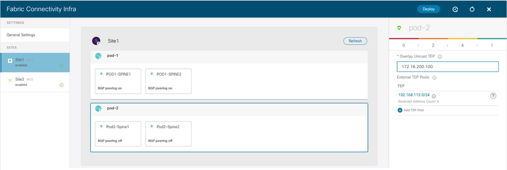
Pod Level Configuration for the Newly Added Pod
● Spine Level Configuration: The configuration for the interfaces defined in the infra L3Out is automatically inherited from APIC, as the same interfaces must also be used to send and receive Multi-Site traffic. The only required configuration in the new Pod is defining one of the two spines as BGP Speaker (turning on the “BGP peering” knob), so that it can establish BGP EVPN adjacencies with the spines in the remote Site2.
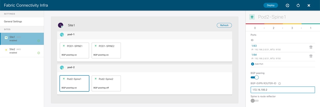
Spine Level Configuration for the Newly Added Pod
Since having two spines configured as BGP Speakers is sufficient for each fabric, after enabling BGP for Pod2-Spine the recommendation is to disable it for Pod1-Spine 2, making this spine simply a Forwarder.
Once the “Deploy” button is hit, the infra configuration is provisioned and the Multi-Pod fabric is successfully added to the Multi-Site domain.
![]()