-
Dial Configuration Guide, Cisco IOS Release 15M&T
- Part 1: Dial Interfaces, Controllers, and Lines
-
Part 2: Modem Configuration and Management
-
Overview of Modem Interfaces
-
Configuring and Managing Integrated Modems
-
1- and 2-Port V.90 Modem WICs for Cisco 2600 and Cisco 3600 Series Multiservice Platforms
-
Call Tracker show Commands Extensions
-
Cisco NM-8AM-V2 and NM-16AM-V2 Analog Modem Network Modules with V.92
-
MICA and NextPort Modem Tech-Support Command Additions
-
PIAFS Wireless Data Protocol Version 2.1 for Cisco MICA Modems
-
V.92 and V.44 Support for Digital Modems
-
V.92 Modem on Hold for Cisco AS5300 and Cisco AS5800 Universal Access Servers
-
V.92 Modem on Hold for Cisco AS5350, Cisco AS5400, and Cisco AS5850 Universal Gateways and Cisco AS5800 Universal Access Servers
-
V.92 Quick Connect for Cisco AS5300 and Cisco AS5800 Universal Access Servers
-
V.92 Quick Connect for Cisco AS5350, Cisco AS5400, and Cisco AS5850 Universal Gateways and Cisco AS5800 Universal Access Servers
-
V.92 Reporting Using RADIUS Attribute v.92-info
-
Configuring and Managing Cisco Access Servers and Dial Shelves
-
Configuring and Managing External Modems
-
Modem Signal and Line States
-
Creating and Using Modem Chat Scripts
-
Cisco Modem User Interface
-
Modem Script and System Script Support in Large-Scale Dial-Out
-
-
Part 3: ISDN Configuration
-
Configuring ISDN BRI
-
Leased and Switched BRI Interface for ETSI NET3
-
ISDN BCAC and Round-Robin Channel Selection Enhancements
-
Configuring Virtual Asynchronous Traffic over ISDN
-
Configuring Modem Use over ISDN BRI
-
Configuring X.25 on ISDN
-
Configuring X.25 on ISDN Using AO/DI
-
Configuring ISDN on Cisco 800 Series Routers
-
- Part 4: Signaling Configuration
-
Part 5: Dial-on-Demand Routing Configuration
-
Preparing to Configure DDR
-
Configuring Legacy DDR Spokes
-
Configuring Legacy DDR Hubs
-
Configuring Peer-to-Peer DDR with Dialer Profiles
-
Dialer Map VRF-Aware for an MPLS VPN
-
Dialer Persistent
-
PPPoE Client DDR Idle-Timer
-
Redial Enhancements
-
Rotating Through Dial Strings
-
Configuring Dialer CEF
-
CEF Support for Dialer Profiles on Cisco 7500 Routers
-
IPv6 Cisco Express Forwarding Switching on Dialer Interfaces
-
Configuring Snapshot Routing
-
- Part 6: Dial-Backup Configuration
- Part 7: Dial-Related Addressing Services
- Part 8: Virtual Templates and Profiles
-
Part 9: PPP Configuration
-
Configuring Asynchronous SLIP and PPP
-
Optimized PPP Negotiation
-
Customer Profile Idle Timer Enhancements for Interesting Traffic
-
Multilink PPP Minimum Links Mandatory
-
Configuring Media-Independent PPP and Multilink PPP
-
PPP/MLP MRRU Negotiation Configuration
-
Troubleshooting Enhancements for Multilink PPP over ATM Link Fragmentation and Interleaving
-
Multichassis Multilink PPP
-
- Part 10: Callback and Bandwidth Allocation Configuration
- Configuring Large-Scale Dial-Out
- Part 11: Dial Access Specialized Features
- Part 12: Dial Access Scenarios
 Feedback
Table Of Contents
Implementing Multichassis Multilink PPP
Prerequisites for Implementing Multichassis Multilink PPP
Restrictions for Implementing Multichassis Multilink PPP
Information About Multichassis Multilink PPP
Stack Groups with an Offload Server
Layer 2 Tunnel Protocols Used with MMP
How to Implement Multichassis Multilink PPP
Verifying and Troubleshooting Stack Group Configuration
Configuring MMP on a Nondialer Interface
Configuring MMP on an Explicitly Defined Dialer Interface with a T1 Controller
Configuring MMP on an Explicitly Defined Dialer Interface with an E1 Controller
Configuring MMP on a Native Dialer Interface
Verifying and Troubleshooting MMP Configurations
Verifying the LCP and NCP States
Debugging Layer 2 Tunnel Protocols Used with MMP
Configuration Examples for Multichassis Multilink PPP
Configuring a Basic Stack Group: Example
Configuring an L2TP Stack Group with an Offload Server: Example
Configuring MMP on a Nondialer Interface: Example
Configuring MMP on an Explicitly Defined Dialer Interface with a T1 Controller: Example
Configuring MMP on an Explicitly Defined Dialer Interface with an E1 Controller: Example
Configuring MMP on a Native Dialer Interface: Example
Feature Information for Multichassis Multilink PPP
Implementing Multichassis Multilink PPP
Multilink PPP (MLP) provides the capability of splitting and recombining packets to a single end system across a logical pipe formed by multiple links. MLP provides bandwidth on demand, reduces transmission latency across WAN links, and provides a method of increasing the size of the maximum receive unit. Multichassis Multilink PPP (MMP) provides the additional capability for links to terminate at multiple routers with different remote addresses. MMP allows network access servers and routers to be stacked together and to appear as a single network access server chassis. MMP handles both analog and digital traffic. MMP allows for easy expansion and scalability and for assured fault tolerance and redundancy.
Module History
This module was first published on May 2, 2005, and last updated on September 26, 2005.
Finding Feature Information in This Module
Your Cisco IOS software release may not support all features. To find information about feature support and configuration, use the "Feature Information for Multichassis Multilink PPP" section.
Contents
•
Prerequisites for Implementing Multichassis Multilink PPP
•
•
•
•
•
Prerequisites for Implementing Multichassis Multilink PPP
Note
MMP support on a group of routers requires that each router be configured to support the following:
•
•
Restrictions for Implementing Multichassis Multilink PPP
•
•
•
Information About Multichassis Multilink PPP
To configure MLP you should understand the following concepts:
•
•
Multichassis Multilink PPP
Multilink PPP (MLP) provides the capability of splitting and recombining packets to a single end system across a logical pipe (also called a bundle) formed by multiple links. MLP provides bandwidth on demand and reduces transmission latency across WAN links, and provides a method of increasing the size of the maximum receive unit.
Multichassis Multilink PPP (MMP) provides the additional capability for links to terminate at multiple routers with different remote addresses. MMP can handle both analog and digital traffic. MMP allows for easy expansion and scalability and for assured fault tolerance and redundancy.
MMP is intended for use in networks that have large pools of dial-in users, where a single chassis cannot provide enough dial ports. MMP allows companies to provide a single dialup number to its users and to apply the same solution to analog and digital calls. This feature allows Internet service providers (ISPs), for example, to allocate a single ISDN rotary number to several ISDN PRIs across several routers. This capability allows for easy expansion and scalability and for assured fault tolerance and redundancy.
MMP allows network access servers to be stacked together and to appear as a single network access server chassis so that if one network access server fails, another network access server in the stack can accept calls.
With large-scale dial-out, these features are available for both outgoing and incoming calls.
Stack Group Operation
Routers or access servers are configured to belong to groups of peers called stack groups. All members of the stack group are peers; stack groups do not need a permanent lead router. Any stack group member can answer calls coming from a single access number, which can be an E1 or T1 hunt group. Calls can come in from remote user devices, such as routers, modems, ISDN terminal adapters, and PC cards.
Once a connection is established with one member of a stack group, that member owns the call. If a second call comes in from the same client and a different router answers the call, the router establishes a tunnel and forwards all packets that belong to the call to the router that owns the call.
If a more powerful router is available, it can be configured as an offload server for the stack group. The other stack group members forward all calls to the offload server.
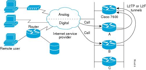
Figure 1 shows a basic stack group scenario.
Figure 1 Basic Stack Group
In this scenario, the first call coming in to the stack group is answered by router A. Router A wins the bidding because it already has the call. When the remote device that initiated the call needs more bandwidth it makes a second call to the stack group. Router D answers the second call, but router A wins the bidding because it is already handling a session with that remote device. Router D then establishes a tunnel to router A and forwards the raw PPP data to router A, which reassembles and resequences the packets. If router D receives more calls from that remote device, it enlarges the tunnel to router A to handle the additional traffic. Router D will not establish an additional tunnel to router A. If more calls come in from that remote device and they are answered by any other router in the stack, that router also establishes a tunnel to router A and forwards the raw PPP data. Router A reassembles the data from all calls from that remote device and passes it to the corporate network as if it had all come through on a single link.
Note
Stack Groups with an Offload Server
Routers or access servers can be configured to belong to groups of peers called stack groups. Any stack group member can answer calls coming from a single access number, which can be an E1 or T1 hunt group. Calls can come in from remote user devices, such as routers, modems, ISDN terminal adapters, and PC cards.
When a more powerful router is available, it can be configured as an offload server for the stack group. The offload server automatically wins the bid for any call. Other members of the stack group answer calls and forward all traffic to the offload server.
Figure 2 shows a stack group scenario with an offload server configured.
Figure 2 Stack Group with an Offload Server
In this scenario, the Cisco 7200 is configured as an offload server. The platform that is configured as an offload server automatically wins the bidding for any call. Other members of the stack group answer calls, establish tunnels, and forward all raw PPP data to the offload server. The offload server reassembles and resequences all the packets that arrive through the stack group and passes it to the corporate network as if it had all come through on a single link.
Note
Stack Group Bidding Protocol
Stack group bidding protocol (SGBP) arbitrates between members of a stack group to establish ownership of a call by evaluating the bids that each platform makes for that call. If all members of a stack group present the same bid, the router or access server that accepted the call will win the bid. In practice, SGBP is usually more complex. The SGBP bid from a stack group member is a function of locality, a configurable weighted metric, CPU type, and the number of existing MLP bundles. For more information about manually configuring SGBP bidding, refer to the "Usage Guidelines" section of the sgbp seed-bid command in the Cisco IOS VPDN Command Reference, Release 12.4.
Layer 2 Tunnel Protocols Used with MMP
Note
When a call must be forwarded from one member of the stack group to the member that owns the call, Layer 2 Forwarding (L2F) or Layer 2 Tunneling Protocol (L2TP) is used. L2F or L2TP performs standard PPP operations up to the authentication phase, but the authentication phase is not completed locally. L2F or L2TP projects the link to the target stack member (the owner of the call), where the authentication phase is resumed and completed.
For more information on the L2TP and L2F protocols, refer to the "VPDN Technology Overview" module in the Cisco IOS VPDN Configuration Guide, Release 12.4.
How to Implement Multichassis Multilink PPP
Note
This section contains the following tasks:
•
•
•
•
Configuring a Stack Group
To configure MMP, you must first configure a stack group. Perform the task in this section to configure a stack group.
Restrictions
•
•
•
–
–
•
SUMMARY STEPS
1.
2.
3.
4.
5.
6.
7.
DETAILED STEPS
What to Do Next
•
•
Verifying and Troubleshooting Stack Group Configuration
To ensure that your stack group is configured and running correctly, perform the following optional task.
SUMMARY STEPS
1.
2.
3.
4.
DETAILED STEPS
Step 1
Enter this command to enable privileged EXEC mode. Enter your password if prompted:
Routera> enableStep 2
Enter this command to display the status of the stack group members.
The following is sample output from the show sgbp command issued on Router A of a four member stack:
Routera# show sgbpGroup Name: stack State: 0 Ref: 0xC07B060Member Name: routerb State: ACTIVE Id: 1Ref: 0xC14256FAddress: 10.1.1.2 Tcb: 0x60B34538Member Name: routerc State: ACTIVE Id: 2Ref: 0xA24256DAddress: 10.1.1.3 Tcb: 0x60B34439Member Name: routerd State: IDLE Id: 3Ref: 0x0Address: 10.1.1.4 Tcb: 0x0The State field displays the status of the member. The State is 0 for the stack group itself, and should be ACTIVE for each of the members of the group. IDLE is a valid state for remote stack members that are intentionally inactive.Step 3
Enter this command to enable the display of debug messages for authentication between stack members.
The following output displays successful authentication between two stack members:
Routera# debug sgbp hellos%SGBP-7-CHALLENGE: Send Hello Challenge to routerb group stack1%SGBP-7-CHALLENGED: Hello Challenge message from member routerb (10.1.1.2)%SGBP-7-RESPONSE: Send Hello Response to routerb group stack1%SGBP-7-CHALLENGE: Send Hello Challenge to routerb group stack1%SGBP-7-RESPONDED: Hello Response message from member routerb (10.1.1.2)%SGBP-7-AUTHOK: Send Hello Authentication OK to member routerb (10.1.1.2)%SGBP-7-INFO: Addr = 10.1.1.2 Reference = 0xC347DF7%SGBP-5-ARRIVING: New peer event for member routerbThis output shows Router A sending a successful Challenge Handshake Authentication Protocol (CHAP) challenge to and receiving a response from routerb. Similarly, Router B sends out a challenge and receives a response from routera.
If authentication fails, you may see one of the following messages in your debug output:
Routera# debug sgbp hellos%SGBP-7-AUTHFAILED - Member routerb failed authenticationThis error message means that the remote Router B password for the stack group does not match the password defined on Router A. To correct this error, make sure that both Router A and Router B have the same password defined.
Routera# debug sgbp hellos%SGBP-7-NORESP -Fail to respond to routerb group stack1, may not have passwordThis error message means that Router A does not have a username or password defined. To correct this error, define a common password across all stack members.
Step 4
Enter this command to enable the display of debug messages about routing problems between members of a stack group.
One common configuration error is setting a source IP address for a stack member that does not match the locally defined IP address for the same stack member. The following debug output shows the error message that results from this misconfiguration:
Routera# debug sgbp error%SGBP-7-DIFFERENT - routerb's addr 10.1.1.2 is different from hello's addr 10.3.4.5This error message means that the source IP address of the SGBP hello received from Router B does not match the IP address configured locally for Router B (through the sgbp member command). Correct this configuration error by going to Router B and checking for multiple interfaces by which the SGBP hello can transmit the message.
Another common error message is:
Routera# debug sgbp error%SGBP-7-MISCONF, Possible misconfigured member routerk (10.1.1.6)This error message means that you do not have Router K defined locally, but another stack member does. Correct this configuration error by defining Router K across all members of the stack group.
The following error message indicates that an SGBP peer is leaving the stack group:
Routera# debug sgbp error%SGBP-7-LEAVING:Member routerc leaving group stack1This error message indicates that the peer Router C is leaving the stack group. Router C could be leaving the stack group intentionally, or a connectivity problem may exist.
The following error message indicates that an SGBP event was detected from an unknown peer:
Routera# debug sgbp error%SGBP-7-UNKNOWPEER:Event 0x10 from peer at 172.21.54.3An SGBP event came from a network host that was not recognizable as an SGBP peer. Check to see if a network media error could have corrupted the address, or if peer equipment is malfunctioning to generate corrupted packets. Depending on the network topology and firewall, SGBP packets from a nonpeer host could indicate probing and attempts to breach security. If there is a chance your network is under attack, obtain knowledgeable assistance.
What to Do Next
Once your stack group has been configured, proceed to the "Configuring MMP" section.
Configuring MMP
Once a stack group has been configured, you must configure MMP on the members of the stack group. The MMP configuration of the stack group members depends on the type of interfaces you have. You must choose the configuration task that matches the type of interface you are configuring.
If you are configuring MMP on asynchronous, serial, or other nondialer interfaces, you may choose to support MMP without any dialer configuration on those interfaces. In this case, you must define a virtual template to serve as the source of configuration information for the virtual access interfaces. Virtual access interfaces serve as both bundle interfaces and projected PPP links. These interfaces are dynamically created on demand.
If dialers are configured on physical interfaces, or the interface is a native dialer such as ISDN PRIs and BRIs, no virtual template needs to be defined. The virtual access interface acts as a passive interface, buttressed between the dialer interface and the physical interfaces associated with the dialer interface. Only the PPP commands from the dialer interface configuration will be applied to the bundle interface and projected PPP links.
Perform one of the following tasks depending on the type of interface you are configuring:
•
•
•
•
This section also contains an optional Troubleshooting Tips section, which applies to MMP configurations on all types of interfaces.
•
Configuring MMP on a Nondialer Interface
Perform this task if you are configuring MMP on a physical interface that is not configured as a dialer.
Prerequisites
A stack group must be configured before MMP is implemented. To configure a stack group, perform the task in the "Configuring a Stack Group" section.
SUMMARY STEPS
1.
2.
3.
4.
5.
6.
7.
8.
9.
10.
DETAILED STEPS
What to Do Next
You may perform the optional tasks in the "Verifying and Troubleshooting MMP Configurations" section.
Configuring MMP on an Explicitly Defined Dialer Interface with a T1 Controller
Perform this task to configure a physical interface as a dialer interface and enable MMP. Perform this task if you are configuring MMP on a dialer interface that is not a native dialer and you have a T1 PRI controller.
Prerequisites
A stack group must be configured before MMP is implemented. To configure a stack group, perform the task in the "Configuring a Stack Group" section.
SUMMARY STEPS
1.
2.
3.
4.
5.
6.
7.
8.
9.
10.
11.
12.
13.
14.
15.
16.
17.
18.
19.
20.
21.
22.
23.
DETAILED STEPS
Step 1
enable
Example:Router> enable
Enables privileged EXEC mode.
•
Step 2
configure terminal
Example:Router# configure terminal
Enters global configuration mode.
Step 3
interface dialer dialer-rotary-group-number
Example:Router(config)# interface dialer 1
Defines a dialer rotary group and enters interface configuration mode.
Step 4
ip unnumbered type number
Example:Router(config-if)# ip unnumbered ethernet 0
Enables IP processing on a serial interface without assigning an explicit IP address to the interface.
Note
Step 5
dialer in-band [no-parity | odd-parity]
Example:Router(config-if)# dialer in-band
(Optional) Specifies that dial-on-demand routing (DDR) is to be supported.
Step 6
dialer-group group-number
Example:Router(config-if)# dialer group 1
Controls access by configuring an interface to belong to a specific dialing group.
Step 7
dialer idle-timeout seconds [inbound | either]
Example:Router(config-if)# dialer idle timeout 400
(Optional) Specifies the duration of idle time before a line is disconnected.
Note
Note
Step 8
encapsulation type
Example:Router(config-if)# encapsulation ppp
Sets the encapsulation method used by the interface.
Step 9
ppp multilink [bap]
Example:Router(config-if)# ppp multilink
Enables MLP on an interface and, optionally, enables BACP and its BAP subset for dynamic bandwidth allocation.
Step 10
ppp authentication protocol1 [protocol2...] [if-needed] [list-name | default] [callin] [one-time] [optional]
Example:Router(config-if)# ppp authentication chap
Enables CHAP or PAP or both and specifies the order in which CHAP and PAP authentication is selected on the interface.
Step 11
exit
Example:Router(config-if)# exit
Exits interface configuration mode.
Step 12
controller t1 number
Example:Router(config)# controller t1 0
Configures a T1 controller and enters controller configuration mode.
Note
Step 13
framing {sf | esf}
Example:Router(config-controller)# framing esf
Selects the frame type for the T1 data line.
Step 14
linecode {ami | b8zs}
Example:Router(config-controller)# linecode b8zs
Selects the line-code type for T1 lines.
Step 15
pri-group timeslots timeslot-range [nfas_d {backup | none | primary {nfas_int number | nfas_group number | rlm-group number}} | service]
Example:Router(config-controller)# pri-group timeslots 1-24
Specifies an ISDN PRI group on a channelized T1 or E1 controller and to releases the ISDN PRI signaling time slot.
Step 16
exit
Example:Router(config-controller)# exit
Exits controller configuration mode.
Step 17
interface serial controller-number:timeslot
Example:Router(config)# interface serial 0:23
Specifies a serial interface created on a channelized E1 or channelized T1 controller (for ISDN PRI, channel-associated signaling, or robbed-bit signaling) and enters interface configuration mode.
Note
Step 18
no ip address
Example:Router(config-if)# no ip address
Disables IP processing on an interface.
Step 19
encapsulation type
Example:Router(config-if)# encapsulation ppp
Sets the encapsulation method used by the interface.
Step 20
ppp multilink [bap]
Example:Router(config-if)# ppp multilink
Enables MLP on an interface and, optionally, enables BACP and its BAP subset for dynamic bandwidth allocation.
Step 21
ppp authentication protocol1 [protocol2...] [if-needed] [list-name | default] [callin] [one-time] [optional]
Example:Router(config-if)# ppp authentication chap
Enables CHAP or PAP or both and specifies the order in which CHAP and PAP authentication is selected on the interface.
Step 22
dialer rotary-group interface-number
Example:Router(config-if)# dialer rotary-group 1
Includes a specified interface in a dialer rotary group.
Step 23
dialer-group group-number
Example:Router(config-if)# dialer-group 1
(Optional) Controls access by configuring an interface to belong to a specific dialing group.
What to Do Next
You may perform the optional tasks in the "Verifying and Troubleshooting MMP Configurations" section.
Configuring MMP on an Explicitly Defined Dialer Interface with an E1 Controller
Perform this task to configure a physical interface as a dialer interface and enable MMP. Perform this task if you are configuring MMP on a dialer interface that is not a native dialer and you have an E1 PRI controller.
Prerequisites
A stack group must be configured before MMP is implemented. To configure a stack group, perform the task in the "Configuring a Stack Group" section.
SUMMARY STEPS
1.
2.
3.
4.
5.
6.
7.
8.
9.
10.
11.
12.
13.
14.
15.
16.
17.
18.
19.
20.
21.
22.
23.
DETAILED STEPS
Step 1
enable
Example:Router> enable
Enables privileged EXEC mode.
•
Step 2
configure terminal
Example:Router# configure terminal
Enters global configuration mode.
Step 3
interface dialer dialer-rotary-group-number
Example:Router(config)# interface dialer 1
Defines a dialer rotary group and enters interface configuration mode.
Step 4
ip unnumbered type number
Example:Router(config-if)# ip unnumbered ethernet 0
Enables IP processing on a serial interface without assigning an explicit IP address to the interface.
Note
Step 5
dialer in-band [no-parity | odd-parity]
Example:Router(config-if)# dialer in-band
(Optional) Specifies that dial-on-demand routing (DDR) is to be supported.
Step 6
dialer-group group-number
Example:Router(config-if)# dialer group 1
Controls access by configuring an interface to belong to a specific dialing group.
Step 7
dialer idle-timeout seconds [inbound | either]
Example:Router(config-if)# dialer idle timeout 400
(Optional) Specifies the duration of idle time before a line is disconnected.
Note
Note
Step 8
encapsulation type
Example:Router(config-if)# encapsulation ppp
Sets the encapsulation method used by the interface.
Step 9
ppp multilink [bap]
Example:Router(config-if)# ppp multilink
Enables MLP on an interface and, optionally, enables BACP and its BAP subset for dynamic bandwidth allocation.
Step 10
ppp authentication protocol1 [protocol2...] [if-needed] [list-name | default] [callin] [one-time] [optional]
Example:Router(config-if)# ppp authentication chap
Enables CHAP or PAP or both and specifies the order in which CHAP and PAP authentication is selected on the interface.
Step 11
exit
Example:Router(config-if)# exit
Exits interface configuration mode.
Step 12
controller e1 number
Example:Router(config)# controller e1 0
Configures an E1 controller and enters controller configuration mode.
Note
Step 13
framing {crc4 | no-crc4} [australia]
Example:Router(config-controller)# framing sfadm
Selects the frame type for the E1 data line.
Step 14
linecode {ami | hdb3}
Example:Router(config-controller)# linecode ami
Selects the line-code type for E1 lines.
Step 15
pri-group timeslots timeslot-range [nfas_d {backup | none | primary {nfas_int number | nfas_group number | rlm-group number}} | service]
Example:Router(config-controller)# pri-group timeslots 1-31
Specifies an ISDN PRI group on a channelized T1 or E1 controller and to releases the ISDN PRI signaling time slot.
Step 16
exit
Example:Router(config-controller)# exit
Exits controller configuration mode.
Step 17
interface serial controller-number:timeslot
Example:Router(config)# interface serial 0:15
Specifies a serial interface created on a channelized E1 or channelized T1 controller (for ISDN PRI, channel-associated signaling, or robbed-bit signaling) and enters interface configuration mode.
Note
Step 18
no ip address
Example:Router(config-if)# no ip address
Disables IP processing on an interface.
Step 19
encapsulation type
Example:Router(config-if)# encapsulation ppp
Sets the encapsulation method used by the interface.
Step 20
ppp multilink [bap]
Example:Router(config-if)# ppp multilink
Enables MLP on an interface and, optionally, enables BACP and its BAP subset for dynamic bandwidth allocation.
Step 21
ppp authentication protocol1 [protocol2...] [if-needed] [list-name | default] [callin] [one-time] [optional]
Example:Router(config-if)# ppp authentication chap
Enables CHAP or PAP or both and specifies the order in which CHAP and PAP authentication is selected on the interface.
Step 22
dialer rotary-group interface-number
Example:Router(config-if)# dialer rotary-group 1
Includes a specified interface in a dialer rotary group.
Step 23
dialer-group group-number
Example:Router(config-if)# dialer-group 1
(Optional) Controls access by configuring an interface to belong to a specific dialing group.
What to Do Next
You may perform the optional tasks in the "Verifying and Troubleshooting MMP Configurations" section.
Configuring MMP on a Native Dialer Interface
Perform this task to configure MMP on a native dialer interface (ISDN PRI or BRI).
Prerequisites
A stack group must be configured before MMP is implemented. To configure a stack group, perform the task in the "Configuring a Stack Group" section.
SUMMARY STEPS
1.
2.
3.
4.
5.
6.
7.
8.
9.
DETAILED STEPS
Step 1
enable
Example:Router> enable
Enables privileged EXEC mode.
•
Step 2
configure terminal
Example:Router# configure terminal
Enters global configuration mode.
Step 3
interface serial number
Example:Router(config)# interface serial 0:23
Specifies a serial interface created on a channelized E1 or channelized T1 controller (for ISDN PRI, channel-associated signaling, or robbed-bit signaling) and enters interface configuration mode.
Note
Step 4
ip unnumbered type number
Example:Router(config-if)# ip unnumbered ethernet 0
Enables IP processing on a serial interface without assigning an explicit IP address to the interface.
Step 5
dialer-group group-number
Example:Router(config-if)# dialer-group 1
Controls access by configuring an interface to belong to a specific dialing group.
Step 6
dialer rotary-group interface-number
Example:Router(config-if)# dialer rotary-group 1
Includes a specified interface in a dialer rotary group.
Step 7
encapsulation type
Example:Router(config-if)# encapsulation ppp
Sets the encapsulation method used by the interface.
Step 8
ppp multilink [bap]
Example:Router(config-if)# ppp multilink
Enables MLP on an interface and, optionally, enables BACP and its BAP subset for dynamic bandwidth allocation.
Step 9
ppp authentication protocol1 [protocol2...] [if-needed] [list-name | default] [callin] [one-time] [optional]
Example:Router(config-if)# ppp authentication chap
Enables CHAP or PAP or both and specifies the order in which CHAP and PAP authentication is selected on the interface.
What to Do Next
You may perform the optional tasks in the "Verifying and Troubleshooting MMP Configurations" section.
Verifying and Troubleshooting MMP Configurations
To troubleshoot problems with MMP, perform the following optional tasks:
•
•
Verifying the LCP and NCP States
Perform this task to verify the link control protocol (LCP) and Network Control Protocol (NCP) states on the bundle interface.
SUMMARY STEPS
1.
2.
3.
DETAILED STEPS
Step 1
Enter this command to enable privileged EXEC mode. Enter your password if prompted:
Router> enableStep 2
Enter this command to display status, traffic data, and configuration information about a specified virtual access interface.
The LCP state and IP Control Protocol (IPCP), the NCP for PPP, should be in the Open state. The following output displays the LCP and NCP states for a functional bundle interface:
Router# show interfaces virtual-access 1Virtual-Access1 is up, line protocol is up:LCP Open, Multilink OpenOpen: ipcpStep 3
Enter this command to display statistics for all interfaces configured on the router or access server.
To verify the LCP and NCP states on the stack group member interfaces, issue the show interface command. The LCP state should be open on all member interfaces, but IPCP should be closed. The following output displays the LCP and NCP states for a functional interface on a stack group member:
Router# show interfaces Serial 0:4Serial0:4 is up, line protocol is up:LCP Open, Multilink OpenClosed: ipcp
Debugging Layer 2 Tunnel Protocols Used with MMP
Perform this optional task to verify that the Layer 2 protocol is forwarding projected links properly.
SUMMARY STEPS
1.
2.
3.
4.
DETAILED STEPS
Step 1
Enter this command to enable privileged EXEC mode. Enter your password if prompted:
Router> enableStep 2
Enter this command to display L2TP errors and events that are a part of normal tunnel establishment or shutdown for VPDNs.
Router# debug vpdn eventStep 3
Enter this command to turn on VPDN error debug messages.
Router# debug vpdn errorThe following debug output shows an incoming call being successfully forwarded to the target stack member from the router that accepted the call:
Serial0:21 VPN ForwardingSerial0:21 VPN vpn_forward_user userx is forwardedThe following debug output shows the target stack member successfully receiving the projected link:
Virtual-Access1 VPN PPP LCP accepted sent & rcv CONFACKIf you see the following debug output on the target stack member, verify the definitions of your virtual template interface. The virtual template interface must match the PPP interface parameters of the physical interface that accepted the call.
Virtual-Access1 VPN PPP LCP not accepting rcv CONFACKVirtual-Access1 VPN PPP LCP not accepting sent CONFACKStep 4
Note
Enter this command to enable the display of debug messages used to troubleshoot L2TPv3 and the surrounding Layer 2 tunneling infrastructure.
If you see the following debug output on a stack member, the stack group name and password may not match across all stack members:
Router# debug vpdn l2f-errorL2F Tunnel authentication failed for stackq
Configuration Examples for Multichassis Multilink PPP
This section contains the following configuration examples:
•
•
•
•
•
•
Configuring a Basic Stack Group: Example
The following configuration example creates a basic stack group with three members:
Router A Configuration
username user1 password mypasswordsgbp group stack1sgbp member routerb 10.1.1.2sgbp member routerc 10.1.1.3Router B Configuration
username user1 password mypasswordsgbp group stack1sgbp member routera 10.1.1.1sgbp member routerc 10.1.1.3Router C Configuration
username user1 password mypasswordsgbp group stack1sgbp member routera 10.1.1.1sgbp member routerb 10.1.1.2Configuring an L2TP Stack Group with an Offload Server: Example
The following configuration example creates a stack group with four members, including an offload server. The stack group is configured to use only the L2TP protocol.
Router A Configuration
username user1 password mypasswordsgbp group stack1sgbp member routerb 10.1.1.2sgbp member routerc 10.1.1.3sgbp member routerd 10.1.1.4sgbp protocol l2tpRouter B Configuration
username user1 password mypasswordsgbp group stack1sgbp member routera 10.1.1.1sgbp member routerc 10.1.1.3sgbp member routerd 10.1.1.4sgbp protocol l2tpRouter C Configuration
username user1 password mypasswordsgbp group stack1sgbp member routera 10.1.1.1sgbp member routerb 10.1.1.2sgbp member routerd 10.1.1.4sgbp protocol l2tpRouter D (Offload Server) Configuration
username user1 password mypasswordsgbp group stack1sgbp member routera 10.1.1.1sgbp member routerb 10.1.1.2sgbp member routerc 10.1.1.3sgbp protocol l2tpsgbp seed-bid offloadConfiguring MMP on a Nondialer Interface: Example
The following example configures MMP on a physical interface that is not configured as a dialer:
multilink virtual-template 1ip local pool default 10.10.1.1 10.10.1.100interface virtual-template 1ip unnumbered ethernet 0no ip route-cacheencapsulation pppppp multilinkppp authentication chapConfiguring MMP on an Explicitly Defined Dialer Interface with a T1 Controller: Example
The following example configures MMP on a physical interface that is configured as a dialer:
interface dialer 1ip unnumbered ethernet 0dialer in-banddialer group 1dialer idle-timeout 400encapsulation pppppp multilinkppp authentication chap!controller t1 0framing esflinecode b8zspri-group timeslots 1-24!interface serial 0:23no ip addressencapsulation pppppp multilinkppp authentication chapdialer rotary-group 1dialer-group 1Configuring MMP on an Explicitly Defined Dialer Interface with an E1 Controller: Example
The following example configures MMP on a physical interface that is configured as a dialer:
interface dialer 1ip unnumbered ethernet 0dialer in-banddialer group 1dialer idle-timeout 400encapsulation pppppp multilinkppp authentication chap!controller e1 0framing crc4linecode amipri-group timeslots 1-31!interface serial 0:15no ip addressencapsulation pppppp multilinkppp authentication chapdialer rotary-group 1dialer-group 1Configuring MMP on a Native Dialer Interface: Example
The following example configures MMP on a native dialer interface (ISDN PRI or BRI):
interface serial 0:23ip unnumbered ethernet 0dialer-group 1dialer rotary-group 1encapsulation pppppp multilinkppp authentication chapWhere to Go Next
MMP stack groups that receive calls over L2TP VPDN tunnels can be configured to perform L2TP redirect. Enabling L2TP redirect allows a tunnel server in a stack group to send a redirect message to the NAS if it receives a link that belongs to another tunnel server in the stack group. L2TP redirect increases the scalability of VPDN MMP deployments, and can also be used to load balance calls across a stack group.
For more information about configuring L2TP redirect functionality, refer to the "Configuring Multihop VPDN" module in the Cisco IOS VPDN Configuration Guide, Release 12.4.
Additional References
The following sections provide references related to Multichassis Multilink PPP.
Related Documents
Information about Multilink PPP
"Configuring Media-Independent PPP and Multilink PPP" chapter of the Cisco IOS Dial Technologies Configuration Guide, Release 12.4
Information about virtual templates
The "Configuring Virtual Template Interfaces" chapter of the Cisco IOS Dial Technologies Configuration Guide, Release 12.4
Information about L2F and L2TP
"VPDN Technology Overview" module in the Cisco IOS VPDN Configuration Guide, Release 12.4
Information on multihop VPDN and L2TP redirect
"Configuring Multihop VPDN" module in the Cisco IOS VPDN Configuration Guide, Release 12.4
VPDN commands: complete command syntax, command mode, defaults, usage guidelines, and examples
Cisco IOS VPDN Command Reference, Release 12.4
Dial Technologies commands: complete command syntax, command mode, defaults, usage guidelines, and examples
Cisco IOS Dial Technologies Command Reference, Release 12.4
Standards
MIBs
None
To locate and download MIBs for selected platforms, Cisco IOS releases, and feature sets, use Cisco MIB Locator found at the following URL:
RFCs
Technical Assistance
Feature Information for Multichassis Multilink PPP
Table 1 lists the features in this module and provides links to specific configuration information. Only features that were introduced or modified in Cisco IOS Release 12.2(1) or a later release appear in the table.
Not all commands may be available in your Cisco IOS software release. For details on when support for a specific command was introduced, see the command reference documentation.
Cisco IOS software images are specific to a Cisco IOS software release, a feature set, and a platform. Use Cisco Feature Navigator to find information about platform support and Cisco IOS software image support. Access Cisco Feature Navigator at http://www.cisco.com/go/fn. You must have an account on Cisco.com. If you do not have an account or have forgotten your username or password, click Cancel at the login dialog box and follow the instructions that appear.
Note
Cisco and the Cisco Logo are trademarks of Cisco Systems, Inc. and/or its affiliates in the U.S. and other countries. A listing of Cisco's trademarks can be found at www.cisco.com/go/trademarks. Third party trademarks mentioned are the property of their respective owners. The use of the word partner does not imply a partnership relationship between Cisco and any other company. (1005R)
Any Internet Protocol (IP) addresses and phone numbers used in this document are not intended to be actual addresses and phone numbers. Any examples, command display output, network topology diagrams, and other figures included in the document are shown for illustrative purposes only. Any use of actual IP addresses or phone numbers in illustrative content is unintentional and coincidental.
© 2001--2009 Cisco Systems, Inc. All rights reserved.