-
Dial Configuration Guide, Cisco IOS Release 15M&T
- Part 1: Dial Interfaces, Controllers, and Lines
-
Part 2: Modem Configuration and Management
-
Overview of Modem Interfaces
-
Configuring and Managing Integrated Modems
-
1- and 2-Port V.90 Modem WICs for Cisco 2600 and Cisco 3600 Series Multiservice Platforms
-
Call Tracker show Commands Extensions
-
Cisco NM-8AM-V2 and NM-16AM-V2 Analog Modem Network Modules with V.92
-
MICA and NextPort Modem Tech-Support Command Additions
-
PIAFS Wireless Data Protocol Version 2.1 for Cisco MICA Modems
-
V.92 and V.44 Support for Digital Modems
-
V.92 Modem on Hold for Cisco AS5300 and Cisco AS5800 Universal Access Servers
-
V.92 Modem on Hold for Cisco AS5350, Cisco AS5400, and Cisco AS5850 Universal Gateways and Cisco AS5800 Universal Access Servers
-
V.92 Quick Connect for Cisco AS5300 and Cisco AS5800 Universal Access Servers
-
V.92 Quick Connect for Cisco AS5350, Cisco AS5400, and Cisco AS5850 Universal Gateways and Cisco AS5800 Universal Access Servers
-
V.92 Reporting Using RADIUS Attribute v.92-info
-
Configuring and Managing Cisco Access Servers and Dial Shelves
-
Configuring and Managing External Modems
-
Modem Signal and Line States
-
Creating and Using Modem Chat Scripts
-
Cisco Modem User Interface
-
Modem Script and System Script Support in Large-Scale Dial-Out
-
-
Part 3: ISDN Configuration
-
Configuring ISDN BRI
-
Leased and Switched BRI Interface for ETSI NET3
-
ISDN BCAC and Round-Robin Channel Selection Enhancements
-
Configuring Virtual Asynchronous Traffic over ISDN
-
Configuring Modem Use over ISDN BRI
-
Configuring X.25 on ISDN
-
Configuring X.25 on ISDN Using AO/DI
-
Configuring ISDN on Cisco 800 Series Routers
-
- Part 4: Signaling Configuration
-
Part 5: Dial-on-Demand Routing Configuration
-
Preparing to Configure DDR
-
Configuring Legacy DDR Spokes
-
Configuring Legacy DDR Hubs
-
Configuring Peer-to-Peer DDR with Dialer Profiles
-
Dialer Map VRF-Aware for an MPLS VPN
-
Dialer Persistent
-
PPPoE Client DDR Idle-Timer
-
Redial Enhancements
-
Rotating Through Dial Strings
-
Configuring Dialer CEF
-
CEF Support for Dialer Profiles on Cisco 7500 Routers
-
IPv6 Cisco Express Forwarding Switching on Dialer Interfaces
-
Configuring Snapshot Routing
-
- Part 6: Dial-Backup Configuration
- Part 7: Dial-Related Addressing Services
- Part 8: Virtual Templates and Profiles
-
Part 9: PPP Configuration
-
Configuring Asynchronous SLIP and PPP
-
Optimized PPP Negotiation
-
Customer Profile Idle Timer Enhancements for Interesting Traffic
-
Multilink PPP Minimum Links Mandatory
-
Configuring Media-Independent PPP and Multilink PPP
-
PPP/MLP MRRU Negotiation Configuration
-
Troubleshooting Enhancements for Multilink PPP over ATM Link Fragmentation and Interleaving
-
Multichassis Multilink PPP
-
- Part 10: Callback and Bandwidth Allocation Configuration
- Configuring Large-Scale Dial-Out
- Part 11: Dial Access Specialized Features
- Part 12: Dial Access Scenarios
 Feedback
Table Of Contents
Cisco Modems and Cisco IOS Modem Features
Logical Constructs in Modem Configurations
Modem Lines and Asynchronous Interfaces
Asynchronous Line Configuration
Absolute Versus Relative Line Numbers
Line and Modem Numbering Issues
Decimal TCP Port Numbers for Line Connections
Signal and Flow Control Overview
Overview of Modem Interfaces
This chapter describes modem interfaces in the following sections:
•
Cisco Modems and Cisco IOS Modem Features
•
To identify the hardware platform or software image information associated with a feature, use the Feature Navigator on Cisco.com to search for information about the feature or refer to the software release notes for a specific release. For more information, see the "Identifying Supported Platforms" section in the "Using Cisco IOS Software" chapter.
For a complete description of the modem support commands in this chapter, refer to the Cisco IOS Modem Command Reference. To locate documentation of other commands that appear in this chapter, use the command reference master index or search online.
Cisco Modems and Cisco IOS Modem Features
Deciding which asynchronous features to use, to some degree, depends on your hardware configuration. All Cisco access servers must have their asynchronous interfaces and lines configured for network protocol support. Commands entered in asynchronous interface mode configure protocol-specific parameters for asynchronous interfaces, whereas commands entered in line configuration mode configure the physical and logical aspects for the same port.
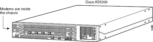
Modems inside high-end access servers need a localized modem country code. This code is projected from the Cisco IOS software to the onboard modems using the modem country {mica | microcom_hdms} country command. The following are high-end access servers: Cisco AS5800, Cisco AccessPath, Cisco AS5300, and the Cisco AS5200.
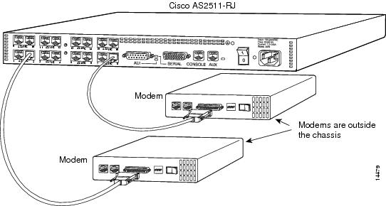
Modems externally attached to low-end access servers need to receive initialization strings from the modem autoconfigure discovery command.
Figure 1 shows a Cisco AS2511-RJ access server. Figure 2 shows a Cisco AS5300 access server. Notice that modems are either inside or outside the chassis, depending on the product model.
Figure 1 Cisco AS2511-RJ Access Server
Figure 2 Cisco AS5300 Access Server
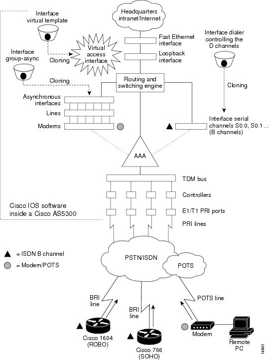
Cisco IOS Modem Components
Different components inside Cisco IOS software work together to enable remote clients to dial in and send packets. Figure 3 shows one Cisco AS5300 access server that is receiving calls from a remote office, branch office (ROBO); small office, home office (SOHO); and modem client.
Depending on your network scenario, you may encounter all of the components in Figure 3. For example, you might decide to create a virtual IP subnet by using a loopback interface. This step saves address space. Virtual subnets can exist inside devices that you advertise to your backbone. In turn, IP packets get relayed to remote PCs, which route back to the central site.
Figure 3 Cisco IOS Modem Concepts
Logical Constructs in Modem Configurations
A logical construct stores core protocol characteristics to assign to physical interfaces. No data packets are forwarded to a logical construct. Cisco uses three types of logical constructs in its access servers and routers. These constructs are described in the following sections:
•
•
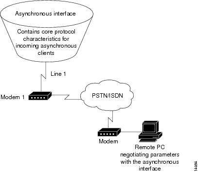
Asynchronous Interfaces
An asynchronous interface assigns network protocol characteristics to remote asynchronous clients that are dialing in through physical terminal lines and modems. (See Figure 4.)
Use the interface async command to create and configure an asynchronous interface.
Figure 4 Logical Construct for an Asynchronous Interface
To enable clients to dial in, you must configure two asynchronous components: asynchronous lines and asynchronous interfaces. Asynchronous interfaces correspond to physical terminal lines. For example, asynchronous interface 1 corresponds to tty line 1.
Commands entered in asynchronous interface mode configure protocol-specific parameters for asynchronous interfaces, whereas commands entered in line configuration mode configure the physical aspects for the same port.
Specifically, you configure asynchronous interfaces to support PPP connections. An asynchronous interface on an access server or router can be configured to support the following functions:
•
•
•
•
•
•
Group Asynchronous Interfaces
A group asynchronous interface is a parent interface that stores core protocol characteristics and projects them to a specified range of asynchronous interfaces. Asynchronous interfaces clone protocol information from group asynchronous interfaces. No data packets arrive in a group asynchronous interface.
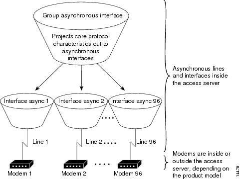
By setting up a group asynchronous interface, you also eliminate the need to repeatedly configure identical configuration information across several asynchronous interfaces. For example, on a Cisco AS5300 one group asynchronous interface is used instead of 96 individual asynchronous interfaces. (See Figure 5.)
The following example shows a group asynchronous configuration for a Cisco AS5300 access server loaded with one 4-port ISDN PRI card and 96 MICA modems:
Router(config)# interface group-async 1Router(config-if)# ip unnumbered loopback 0Router(config-if)# encapsulation pppRouter(config-if)# async mode interactiveRouter(config-if)# peer default ip address pool dialin_poolRouter(config-if)# no cdp enableRouter(config-if)# ppp authentication chap pap dialinRouter(config-if)# group-range 1 96To configure multiple asynchronous interfaces at the same time (with the same parameters), you can assign each asynchronous interface to a group and then configure the group. Configurations throughout this guide configure group asynchronous interfaces, rather than each interface separately.
If you want to configure different attributes on different asynchronous interfaces, do not assign them to the group or assign different interfaces to different groups. After assigning asynchronous interfaces to a group, you cannot configure these interfaces separately. For example, on a Cisco AS5300 access server in a T1 configuration, you could assign asynchronous interfaces 1 to 48 as part of one group (such as group-async1) and asynchronous interfaces 49 to 96 as part of another group (group-async2). You can also use the member command to perform a similar grouping function.
Modem Lines and Asynchronous Interfaces
Modems attach to asynchronous lines, which in turn attach to asynchronous interfaces. Depending on the type of access server you have, these components appear outside or inside the physical chassis. Figure 5 shows the logical relationships among modems, asynchronous lines, asynchronous interfaces, and group asynchronous interfaces. All these components work together to deliver packets as follows:
•
•
•
Note
Figure 5 Modems, Lines, and Asynchronous Interfaces
Use the interface group-async command to create and configure a group asynchronous interface. The following example shows a group asynchronous configuration for a Cisco AS5300 access server loaded with one 4-port ISDN PRI card and 96 MICA modems:
Router(config)# interface group-async 1Router(config-if)# ip unnumbered loopback 0Router(config-if)# encapsulation pppRouter(config-if)# async mode interactiveRouter(config-if)# peer default ip address pool dialin_poolRouter(config-if)# no cdp enableRouter(config-if)# ppp authentication chap pap dialinRouter(config-if)# group-range 1 96Modem Calls
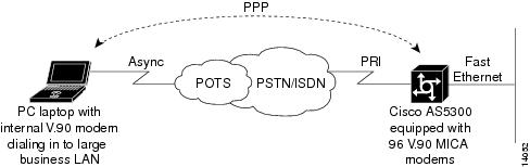
Modem calls travel through traditional telephone and ISDN lines. Regardless of the media used, these calls are initiated by a modem and terminate on another modem at the remote end.
Figure 6 shows a remote laptop using a V.90 internal modem to dial in to a Cisco AS5300 access server, which is loaded with 96 internal V.90 MICA technologies modems.
Figure 6 Remote Node Dialing In to a Cisco AS5300 Access Server
Asynchronous Line Configuration
Asynchronous line configuration commands configure ports for the following options:
•
•
•
•
To enter line configuration mode, first connect to the console port of the access server and enter privileged EXEC mode. Then enter global configuration mode and finally enter line configuration mode for the asynchronous lines that you want to configure. The following example shows how you enter line configuration mode for lines 1 through 16:
Router> enableRouter# configure terminalRouter(config)# line 1 16Router(config-line)#Absolute Versus Relative Line Numbers
When you enter line configuration mode, you can specify an absolute line number or a relative line number. For example, absolute line number 20 is vty 2 (line 18 is vty 0). Referring to lines in a relative format is often easier than attempting to recall the absolute number of a line on a large system. Internally, the router uses absolute line numbers.
On all routers except the Cisco AS5350, AS5400, AS5800, AS5850 access servers, you can view all of the absolute and relative line numbers using the show users all EXEC command.
In the following sample display, absolute line numbers are listed at the far left. Relative line numbers are in the third column, after the line type. The second virtual terminal line, vty 1, is absolute line number 3. Compare the line numbers in this sample display to the output from the show line command.
Line User Host(s) Idle Location0 con 01 aux 02 vty 0 incoming 0 SERVER.COMPANY.COM3 vty 14 vty 25 vty 36 vty 4On the Cisco AS5350, AS5400, AS5800, AS5850 access servers, you can view the absolute and relative line numbers with the following commands:
•
•
The following example shows the information displayed with the show users all | exclude tty|Interface command:
Router# show users all | exclude tty | InterfaceLine User Host(s) Idle Location* 0 con 0 idle 00:00:001 aux 0 00:00:002 vty 0 00:00:003 vty 1 00:00:004 vty 2 00:00:005 vty 3 00:00:006 vty 4 00:00:00The following example shows the information displayed with the show controller async | include tty command:
Router# show controller async | include tty
Controller information for Async2/00 (tty324)Controller information for Async2/01 (tty325)Controller information for Async2/02 (tty326)...Compare the line numbers in this sample display to the output from the show line command.
Line and Modem Numbering Issues
The tty line numbering scheme used by your access server or router is specific to your product and its hardware configuration. Refer to the product-specific documentation that came with your product for line numbering scheme information.
For example, the Cisco AS5200 access server has tty lines that map directly to integrated modems, as shown in Table 1. Depending on the shelf, slot, and port physical architecture of the access server, the modem and tty line number schemes will change.
As shown in Table 1, physical terminal lines 1 through 24 directly connect to modems 1/0 through 1/23, which are installed in the first chassis slot in this example. Physical terminal lines 25 through 48 directly connect to modems 2/0 through 2/23, which are installed in the second slot.
Decimal TCP Port Numbers for Line Connections
Connections to an individual line are most useful when a dial-out modem, parallel printer, or serial printer is attached to that line. To connect to an individual line, the remote host or terminal must specify a particular TCP port on the router.
If reverse XRemote is required, the port is 9000 (decimal) plus the decimal value of the line number.
If a raw TCP stream is required, the port is 4000 (decimal) plus the decimal line number. The raw TCP stream is usually the required mode for sending data to a printer.
If Telnet protocols are required, the port is 2000 (decimal) plus the decimal value of the line number. The Telnet protocol might require that Return characters be translated into Return and line-feed character pairs. You can turn off this translation by specifying the Telnet binary mode option. To specify this option, connect to port 6000 (decimal) plus the decimal line number.
For example, a laser printer is attached to line 10 of a Cisco 2511 router. Such a printer usually uses XON/XOFF software flow control. Because the Cisco IOS software cannot receive an incoming connection if the line already has a process, you must ensure that an EXEC session is not accidentally started. You must, therefore, configure it as follows:
line 10flowcontrol softwareno execA host that wants to send data to the printer would connect to the router on TCP port 4008, send the data, and then close the connection. (Remember that line number 10 octal equals 8 decimal.)
Signal and Flow Control Overview
The EIA/TIA-232 output signals are Transmit Data (TXDATA), Data Terminal Ready (DTR), and Ready To Send (RTS—Cisco 2500 routers only). The input signals are Receive Data (RXDATA), Clear to Send (CTS), and RING. The sixth signal is ground. Depending on the type of modem control your modem uses, these names may or may not correspond to the standard EIA/TIA-232 signals.
Dialup modems that operate over normal telephone lines at speeds of 28800 bps use hardware flow control to stop the data from reaching the host by toggling an EIA/TIA-232 signal when their limit is reached.
In addition to hardware flow control, modems require special software configuring. For example, they must be configured to create an EXEC session when a user dials in and to hang up when the user exits the EXEC. These modems also must be configured to close any existing network connections if the telephone line hangs up in the middle of a session.
Cisco and the Cisco Logo are trademarks of Cisco Systems, Inc. and/or its affiliates in the U.S. and other countries. A listing of Cisco's trademarks can be found at www.cisco.com/go/trademarks. Third party trademarks mentioned are the property of their respective owners. The use of the word partner does not imply a partnership relationship between Cisco and any other company. (1005R)
Any Internet Protocol (IP) addresses and phone numbers used in this document are not intended to be actual addresses and phone numbers. Any examples, command display output, network topology diagrams, and other figures included in the document are shown for illustrative purposes only. Any use of actual IP addresses or phone numbers in illustrative content is unintentional and coincidental.
2001-2009 Cisco Systems, Inc. All rights reserved.