-
Dial Configuration Guide, Cisco IOS Release 15M&T
- Part 1: Dial Interfaces, Controllers, and Lines
-
Part 2: Modem Configuration and Management
-
Overview of Modem Interfaces
-
Configuring and Managing Integrated Modems
-
1- and 2-Port V.90 Modem WICs for Cisco 2600 and Cisco 3600 Series Multiservice Platforms
-
Call Tracker show Commands Extensions
-
Cisco NM-8AM-V2 and NM-16AM-V2 Analog Modem Network Modules with V.92
-
MICA and NextPort Modem Tech-Support Command Additions
-
PIAFS Wireless Data Protocol Version 2.1 for Cisco MICA Modems
-
V.92 and V.44 Support for Digital Modems
-
V.92 Modem on Hold for Cisco AS5300 and Cisco AS5800 Universal Access Servers
-
V.92 Modem on Hold for Cisco AS5350, Cisco AS5400, and Cisco AS5850 Universal Gateways and Cisco AS5800 Universal Access Servers
-
V.92 Quick Connect for Cisco AS5300 and Cisco AS5800 Universal Access Servers
-
V.92 Quick Connect for Cisco AS5350, Cisco AS5400, and Cisco AS5850 Universal Gateways and Cisco AS5800 Universal Access Servers
-
V.92 Reporting Using RADIUS Attribute v.92-info
-
Configuring and Managing Cisco Access Servers and Dial Shelves
-
Configuring and Managing External Modems
-
Modem Signal and Line States
-
Creating and Using Modem Chat Scripts
-
Cisco Modem User Interface
-
Modem Script and System Script Support in Large-Scale Dial-Out
-
-
Part 3: ISDN Configuration
-
Configuring ISDN BRI
-
Leased and Switched BRI Interface for ETSI NET3
-
ISDN BCAC and Round-Robin Channel Selection Enhancements
-
Configuring Virtual Asynchronous Traffic over ISDN
-
Configuring Modem Use over ISDN BRI
-
Configuring X.25 on ISDN
-
Configuring X.25 on ISDN Using AO/DI
-
Configuring ISDN on Cisco 800 Series Routers
-
- Part 4: Signaling Configuration
-
Part 5: Dial-on-Demand Routing Configuration
-
Preparing to Configure DDR
-
Configuring Legacy DDR Spokes
-
Configuring Legacy DDR Hubs
-
Configuring Peer-to-Peer DDR with Dialer Profiles
-
Dialer Map VRF-Aware for an MPLS VPN
-
Dialer Persistent
-
PPPoE Client DDR Idle-Timer
-
Redial Enhancements
-
Rotating Through Dial Strings
-
Configuring Dialer CEF
-
CEF Support for Dialer Profiles on Cisco 7500 Routers
-
IPv6 Cisco Express Forwarding Switching on Dialer Interfaces
-
Configuring Snapshot Routing
-
- Part 6: Dial-Backup Configuration
- Part 7: Dial-Related Addressing Services
- Part 8: Virtual Templates and Profiles
-
Part 9: PPP Configuration
-
Configuring Asynchronous SLIP and PPP
-
Optimized PPP Negotiation
-
Customer Profile Idle Timer Enhancements for Interesting Traffic
-
Multilink PPP Minimum Links Mandatory
-
Configuring Media-Independent PPP and Multilink PPP
-
PPP/MLP MRRU Negotiation Configuration
-
Troubleshooting Enhancements for Multilink PPP over ATM Link Fragmentation and Interleaving
-
Multichassis Multilink PPP
-
- Part 10: Callback and Bandwidth Allocation Configuration
- Configuring Large-Scale Dial-Out
- Part 11: Dial Access Specialized Features
- Part 12: Dial Access Scenarios
 Feedback
Table Of Contents
Configuring Modem Use over ISDN BRI
How to Configure Modem over ISDN BRI
Verifying ISDN BRI Interface Configuration
Configuration Examples for Modem over ISDN BRI
BRI Interface Configuration Example
Complete Configuration Examples
Configuring Modem Use over ISDN BRI
This chapter describes how to configure the Modem over ISDN BRI feature. It includes the following main sections:
•
How to Configure Modem over ISDN BRI
•
•
Before beginning the tasks in this chapter, check your system for the following hardware and software:
•
–
–
–
–
–
These digital modem network modules do not have their own network connections, but instead handle analog calls passing through other router interfaces. BRI modules can provide their ISDN connectivity. Other modules, such as Ethernet, can provide connectivity to the LAN. The digital modem module acts as a pool of available modems that can be used for both incoming and outgoing calls. Digital modem network modules do not support BRI voice interface cards or wide-area network (WAN) interface cards.
•
–
–
–
–
The version level is available from the show diag command, which displays the version number as the part number.
If your BRI network module is a version lower than those cited or you need more details, refer to the Cisco.com Field Notice titled Using Digital Modems with the Cisco 3600 Basic Rate Interface (BRI) Network Module Upgrade in the Access Products index. If your existing Cisco BRI network module is one of those listed and does not support the Modem over ISDN BRI feature, Cisco will upgrade the module at no charge.
•
Before you can configure a Cisco 3640 router to provide Modem over ISDN BRI connectivity, you must also perform the following tasks:
•
•
•
•
For more information about the physical characteristics of the BRI network modules and their digital modem support, or instructions on how to install the network or modem modules, either refer to the Cisco 3600 series Network Module Hardware Installation Guide that came with your BRI network module or view the up-to-date information on CCO.
To identify the hardware platform or software image information associated with a feature, use the Feature Navigator on Cisco.com to search for information about the feature or refer to the software release notes for a specific release. For more information, see the "Identifying Supported Platforms" section in the "Using Cisco IOS Software" chapter.
For a complete description of the Modem over ISDN BRI commands in this chapter, refer to the Cisco IOS Dial Technologies Command Reference. To locate documentation of other commands that appear in this chapter, use the command reference master index or search online.
Modem over ISDN BRI Overview
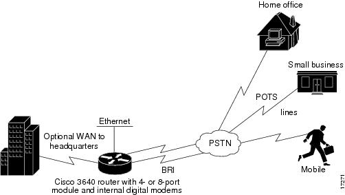
The Modem over ISDN BRI feature for the Cisco 3640 modular access router lowers the cost of remote access by offering high-speed modem and ISDN connectivity for mobile customers, offices, and other remote-access users. Branch offices and enterprises can support analog modem users who call over the Public Switched Telephone Network (PSTN) into BRI interfaces in Cisco 3640 routers.
The digital modem in the router accepts the modem calls at connection speeds as fast as 56 kbps, adhering to the V.90 standard. As shown in Figure 1, the Cisco 3640 router in this way provides rapid access to E-mail and other network services.
Figure 1 Modem over ISDN BRI Feature
The following are benefits of using the Modem over ISDN BRI feature:
•
•
•
How to Configure Modem over ISDN BRI
The Modem over ISDN BRI feature is part of interface configuration for BRI. You configure the BRI interface after you have configured the ISDN global characteristics, which are switch type and TEI negotiation timing. These characteristics can also be defined for each BRI interface, as shown in the following task table.
To set up the BRI interface characteristics, set the global parameters and then configure each interface separately by using the following commands beginning in global configuration mode:
Step 1
Router(config)# isdn switch-type switch-type
Configures the global ISDN switch type to match the service provider switch type. For a list of keywords, see Table 1.
Step 2
Router(config)# isdn tei [first-call | powerup]
Configures when the ISDN TEI negotiation occurs. If this command is not used, negotiation occurs when the router is powered up.
The first-call option is primarily used in European ISDN switch types, such as NET3 networks. The powerup option should be used in most other locations.
Step 3
Router(config)# interface bri slot/port
Begins interface configuration mode to configure parameters for the specified interface.
slot is the location of the BRI module. Valid values are from 0 to 3.
port is an interface number. Valid values are from 0 to 7 if the module is an 8-port BRI network module, or from 0 to 4 if the module is a 4-port BRI network module.
Step 4
Router(config-if)# ip address ip-address mask
Specifies an IP address and subnet for the interface. You can also specify that there is no IP address. For information about IP addressing, see the Release 12.2 Cisco IOS IP Configuration Guide publication.
Step 5
Router(config-if)# encapsulation ppp
Enables PPP encapsulation on the BRI interface. PPP encapsulation is configured for most ISDN communication.
If the router needs to communicate with devices that require a different encapsulation protocol, needs to detect encapsulation on incoming calls automatically, or needs to send traffic over a Frame Relay or X.25 network, see the chapter "Configuring X.25 on ISDN" later in this part, and the chapters in the Dial-on-Demand Routing Configuration part of this publication for information.
Step 6
Router(config-if)# dialer map protocol next-hop-address name hostname speed 56|64 dial-string[:isdn-subaddress]
or
Router(config-if)# dialer map protocol next-hop-address name hostname spc [speed 56 | 64] [broadcast] dial-string[:isdn-subaddress]
(Most locations) Defines the remote protocol address of the recipient, host name, and dialing string; optionally, provide the ISDN subaddress; set the dialer speed to 56 or 64 kbps, as needed.
(Germany) Use the spc keyword to enable ISDN semipermanent connections.
Step 7
Router(config-if)# dialer-group group-number
Assigns the interface to a dialer group to control access to the interface.
Step 8
Router(config-if)# dialer-list dialer-group list access-list-number
Associates the dialer group number with an access list number.
Step 9
Router(config-if)# access-list access-list-number {deny | permit} protocol source address source-mask destination destination-mask
Defines an access list permitting or denying access to specified protocols, sources, or destinations. Permitted packets cause the router to place a call to the destination protocol address.
Step 10
Router(config-if)# no ip-directed broadcast
(Optional) Disables the translation of directed broadcast to physical broadcasts.
Step 11
Router(config-if)# isdn switch-type switch-type
(Optional) Configures the interface ISDN switch type to match the service provider switch type. The interface ISDN switch type overrides the global ISDN switch type on the interface.
For a list of keywords, refer to Table 1.
Step 12
Router(config-if)# isdn tei [first-call | powerup]
(Optional) Determines when ISDN TEI negotiation occurs for an individual interface. This overrides the global configuration command.
Step 13
Router(config-if)# isdn spid1 spid-number [ldn]
Specifies a service profile identifier (SPID) and local directory number for the B1 channel. Currently, only the DMS-100 and NI-1 switch types require SPIDs. Although the Lucent 5ESS switch type might support a SPID, we recommend that you set up that ISDN service without SPIDs.
Step 14
Router(config-if)# isdn spid2 spid-number [ldn]
Specifies a SPID and local directory number for the B2 channel.
Step 15
Router(config-if)# isdn caller number
(Optional) Configure caller ID screening.
Step 16
Router(config-if)# isdn answer1 [called-party-number][:subaddress]
(Optional) Configures called-party number verification for a called-party number or subaddress number in the incoming setup message.
Step 17
Router(config-if)# isdn calling-number calling-number
(Optional) Specifies the calling-party number.
Step 18
Router(config-if)# isdn not-end-to-end [56 | 64]
(Optional) Configures the speed for incoming calls recognized as not ISDN end-to-end.
Step 19
Router(config-if)# isdn incoming-voice modem
Routes incoming voice calls to the modem and treats them as analog data. This step is required for the Modem over ISDN BRI feature.
Step 20
Router(config-if)# isdn disconnect-cause {cause-code-number | busy | not available}
Overrides specific cause codes such as modem availability and resource pooling that are sent to the switch by ISDN applications. When the isdn disconnect-cause command is implemented, the configured cause codes are sent to the switch; otherwise, the default cause codes of the application are sent.
The cause-code-number argument sends a cause code number (submitted as integer 1 through 127) to the switch.
The busy keyword sends the USER BUSY code to the switch.
The not available keyword sends the CHANNEL NOT AVAILABLE code to the switch.
Step 21
Router(config-if)# isdn fast-rollover-delay seconds
(Optional) Configures a delay between fast rollover dials.
Step 22
Router(config-if)# isdn sending-complete
(Optional) Configures the BRI interface to include the Sending Complete information element in the outgoing call Setup message. Used in some geographic locations, such as Hong Kong and Taiwan, where the sending complete information element is required in the outgoing call setup message.
See the section "Configuration Examples for Modem over ISDN BRI" at the end of this chapter for configuration examples.
Verifying ISDN BRI Interface Configuration
Use the show running-config command in EXEC mode to verify the current configuration that is running on the terminal.
Note
The following example shows some of the command output that is relevant to BRI configuration tasks. The bold text in the example are the results of configuration steps such as those shown in the section "How to Configure Modem over ISDN BRI" earlier in this chapter.
Building configuration...Current configuration:!version 12.0no service udp-small-serversservice tcp-small-servers!hostname Router!enable secret 5 $1$c8xi$tObplXsIS.jDeo43yZgq50enable password xxx!username xxxx password x 11x5xx07no ip domain-lookupip host Labhost 172.17.12.1ip host Labhost2 172.17.12.2ip name-server 172.19.169.21!interface Ethernet0ip address 172.17.12.100 255.255.255.192no ip mroute-cacheno ip route-cacheno mop enabled...interface BRI1/7description (408) 555-3777ip address 10.1.1.26 255.255.255.1no ip directed-broadcastencapsulation pppno ip route-cacheno ip mroute-cacheno keepaliveshutdowndialer idle-timeout 180dialer map ip 10.1.1.9 name MDial1 14085550715dialer map ip 10.1.1.14 name MDial2 14085553775dialer-group 1isdn switch-type basic-5essisdn incoming-voice modemisdn disconnect-cause busyno fair-queueno cdp enableppp authentication chapppp multilink...!interface Group-Async1ip unnumbered Loopback0no ip directed-broadcastip tcp header-compression passiveasync mode interactivepeer default ip address pool defaultno fair-queuegroup-range 65 70hold-queue 10 in!router igrp 109network 172.21.0.0!ip local pool local 172.21.50.85 172.21.50.89ip local pool default 10.1.1.1 10.1.1.253ip classlessip route 0.0.0.0 0.0.0.0 172.21.48.1!!map-class dialer VOICEdialer voice-call!map-class dialer DATAdialer-list 1 protocol ip list 101tacacs-server host 172.19.2.74tacacs-server host 192.168.15.197snmp-server community isdn RWsnmp-server enable traps isdn call-informationsnmp-server host 172.25.3.154 traps isdnUse the show interfaces bri number command to verify information about the physical attributes of the ISDN BRI B and D channels. The number argument is the slot location of the BRI module. Valid values are from 0 to 3.
BRI0:1 is down, line protocol is downHardware is BRIMTU 1500 bytes, BW 64 Kbit, DLY 20000 usec, rely 255/255, load 1/255Internet address is 10.1.1.3/27Encapsulation PPP, loopback not set, keepalive not setLCP ClosedClosed: IPCPLast input never, output never, output hang neverLast clearing of "show interface" counters neverQueueing strategy: fifoOutput queue 0/40, 0 drops; input queue 0/75, 0 drops5 minute input rate 0 bits/sec, 0 packets/sec5 minute output rate 0 bits/sec, 0 packets/sec0 packets input, 0 bytes, 0 no bufferReceived 0 broadcasts, 0 runts, 0 giants0 input errors, 0 CRC, 0 frame, 0 overrun, 0 ignored, 0 abort0 packets output, 0 bytes, 0 underruns0 output errors, 0 collisions, 7 interface resets0 output buffer failures, 0 output buffers swapped out0 carrier transitionsConfiguration Examples for Modem over ISDN BRI
This section provides the following examples:
•
•
These examples show configuration of just the Modem over ISDN BRI feature using the interface configuration commands for each interface and a complete configuration showing global configuration, BRI interfaces, and modem configuration.
BRI Interface Configuration Example
The following example shows how to configure each BRI interface on a Cisco 3640 router for the Modem over ISDN BRI feature:
interface BRI0/0no ip addressno ip directed-broadcastencapsulation pppisdn switch-type basic-niisdn spid1 0444000101 9194440001isdn spid2 0444001101 9194440011isdn incoming-voice modem!interface BRI0/1no ip addressno ip directed-broadcastencapsulation pppisdn switch-type basic-niisdn spid1 0444000201 9194440002isdn spid2 0444001201 9194440012isdn incoming-voice modem!interface BRI0/2no ip addressno ip directed-broadcastencapsulation pppisdn switch-type basic-niisdn spid1 0444000301 9194440003isdn spid2 0444001301 9194440013isdn incoming-voice modem!interface BRI0/3no ip addressno ip directed-broadcastencapsulation pppisdn switch-type basic-niisdn spid1 0444000401 9194440004isdn spid2 0444001401 9194440014isdn incoming-voice modem!interface BRI0/4no ip addressno ip directed-broadcastencapsulation pppisdn switch-type basic-niisdn spid1 0444000501 9194440005isdn spid2 0444001501 9194440015isdn incoming-voice modem!interface BRI0/5no ip addressno ip directed-broadcastencapsulation pppisdn switch-type basic-niisdn spid1 0444000601 9194440006isdn spid2 0444001601 9194440016isdn incoming-voice modem!interface BRI0/6no ip addressno ip directed-broadcastencapsulation pppisdn switch-type basic-niisdn spid1 0444000701 9194440007isdn spid2 0444001701 9194440017isdn incoming-voice modem!interface BRI0/7no ip addressno ip directed-broadcastencapsulation pppisdn switch-type basic-niisdn spid1 0444000801 9194440008isdn spid2 0444001801 9194440018isdn incoming-voice modem!interface BRI2/0no ip addressno ip directed-broadcastencapsulation pppisdn switch-type basic-niisdn spid1 0555000101 9195550001isdn spid2 0555001101 9195550011isdn incoming-voice modem!interface BRI2/1no ip addressno ip directed-broadcastencapsulation pppisdn switch-type basic-niisdn spid1 0555000201 9195550002isdn spid2 0555001201 9195550012isdn incoming-voice modem!interface BRI2/2no ip addressno ip directed-broadcastencapsulation pppisdn switch-type basic-niisdn spid1 0555000301 9195550003isdn spid2 0555001301 9195550013isdn incoming-voice modem!interface BRI2/3no ip addressno ip directed-broadcastencapsulation pppisdn switch-type basic-niisdn spid1 0555000401 9195550004isdn spid2 0555001401 9195550014isdn incoming-voice modem!interface BRI2/4no ip addressno ip directed-broadcastencapsulation pppisdn switch-type basic-niisdn spid1 0555000501 9195550005isdn spid2 0555001501 9195550015isdn incoming-voice modem!interface BRI2/5no ip addressno ip directed-broadcastencapsulation pppisdn switch-type basic-niisdn spid1 0555000601 9195550006isdn spid2 0555001601 9195550016isdn incoming-voice modem!interface BRI2/6no ip addressno ip directed-broadcastencapsulation pppisdn switch-type basic-niisdn spid1 0555000701 9195550007isdn spid2 0555001701 9195550017isdn incoming-voice modem!interface BRI2/7no ip addressno ip directed-broadcastencapsulation pppisdn switch-type basic-niisdn spid1 0555000801 9195550008isdn spid2 0555001801 9195550018isdn incoming-voice modem!Complete Configuration Examples
The following example shows a complete configuration for a dial-in router, including a global command, BRI interface configuration, and modem configuration including group-async and dialer commands.
version 12.0service timestamps debug datetime localtimeservice timestamps log uptimeno service password-encryptionservice udp-small-serversservice tcp-small-servers!hostname MBRI_IN!no logging bufferedenable password xxxThe following lines are used for PPP CHAP authentication. Each username and password is associated with one dialer interface.
username async1 password devtestusername async2 password devtestusername async3 password devtestusername async4 password devtestusername async5 password devtestusername async6 password devtestusername async7 password devtestusername async8 password devtestusername async9 password devtestusername async10 password devtestusername async11 password devtestusername async12 password devtestusername async13 password devtestusername async14 password devtestusername async15 password devtestusername async16 password devtestusername async17 password devtestusername async18 password devtestusername async19 password devtestusername async20 password devtestusername async21 password devtestusername async22 password devtestusername async23 password devtestusername async24 password devtestusername async25 password devtestusername async26 password devtestusername async27 password devtestusername async28 password devtestusername async29 password devtestusername async30 password devtestusername FLOYD password devtestusername MBRI_OUT password devtestip subnet-zerono ip domain-lookup!isdn switch-type basic-5essinterface BRI0/0no ip addressno ip directed-broadcastencapsulation pppisdn switch-type basic-niisdn spid1 0444000101 9194440001isdn spid2 0444001101 9194440011isdn incoming-voice modem!interface BRI0/1no ip addressno ip directed-broadcastencapsulation pppisdn switch-type basic-niisdn spid1 0444000201 9194440002isdn spid2 0444001201 9194440012isdn incoming-voice modem!interface BRI0/2no ip addressno ip directed-broadcastencapsulation pppisdn switch-type basic-niisdn spid1 0444000301 9194440003isdn spid2 0444001301 9194440013isdn incoming-voice modem!interface BRI0/3no ip addressno ip directed-broadcastencapsulation pppisdn switch-type basic-niisdn spid1 0444000401 9194440004isdn spid2 0444001401 9194440014isdn incoming-voice modem!interface BRI0/4no ip addressno ip directed-broadcastencapsulation pppisdn switch-type basic-niisdn spid1 0444000501 9194440005isdn spid2 0444001501 9194440015isdn incoming-voice modemno shut!interface BRI0/5no ip addressno ip directed-broadcastencapsulation pppisdn switch-type basic-niisdn spid1 0444000601 9194440006isdn spid2 0444001601 9194440016isdn incoming-voice modem!interface BRI0/6no ip addressno ip directed-broadcastencapsulation pppisdn switch-type basic-niisdn spid1 0444000701 9194440007isdn spid2 0444001701 9194440017isdn incoming-voice modem!interface BRI0/7no ip addressno ip directed-broadcastencapsulation pppisdn switch-type basic-niisdn spid1 0444000801 9194440008isdn spid2 0444001801 9194440018isdn incoming-voice modem!interface BRI2/0no ip addressno ip directed-broadcastencapsulation pppisdn switch-type basic-niisdn spid1 0555000101 9195550001isdn spid2 0555001101 9195550011isdn incoming-voice modem!interface BRI2/1no ip addressno ip directed-broadcastencapsulation pppisdn switch-type basic-niisdn spid1 0555000201 9195550002isdn spid2 0555001201 9195550012isdn incoming-voice modem!interface BRI2/2no ip addressno ip directed-broadcastencapsulation pppisdn switch-type basic-niisdn spid1 0555000301 9195550003isdn spid2 0555001301 9195550013isdn incoming-voice modem!interface BRI2/3no ip addressno ip directed-broadcastencapsulation pppisdn switch-type basic-niisdn spid1 0555000401 9195550004isdn spid2 0555001401 9195550014isdn incoming-voice modem!interface BRI2/4no ip addressno ip directed-broadcastencapsulation pppisdn switch-type basic-niisdn spid1 0555000501 9195550005isdn spid2 0555001501 9195550015isdn incoming-voice modem!interface BRI2/5no ip addressno ip directed-broadcastencapsulation pppisdn switch-type basic-niisdn spid1 0555000601 9195550006isdn spid2 0555001601 9195550016isdn incoming-voice modem!interface BRI2/6no ip addressno ip directed-broadcastencapsulation pppisdn switch-type basic-niisdn spid1 0555000701 9195550007isdn spid2 0555001701 9195550017isdn incoming-voice modem!interface BRI2/7no ip addressno ip directed-broadcastencapsulation pppisdn switch-type basic-niisdn spid1 0555000801 9195550008isdn spid2 0555001801 9195550018isdn incoming-voice modem!interface Ethernet1/0ip address 172.18.16.123 255.255.255.192no ip directed-broadcast!The following example defines a group-async interface for grouping all the digital modems and configuring them together. Group-async configuration is much easier than configuring all 30 digital modems individually.
interface Group-Async1ip unnumbered Ethernet3/1no ip directed-broadcastencapsulation pppload-interval 30dialer in-banddialer pool-member 1async default routingasync mode dedicatedno peer default ip addressno cdp enableppp authentication chapgroup-range 96 125hold-queue 10 inThe following example defines dialer interfaces, associates IP addresses, and sets all the authentication parameters required during the call establishment.
interface Dialer1ip address 10.1.0.1 255.255.0.0no ip directed-broadcastencapsulation pppdialer remote-name async1dialer pool 1dialer-group 1no cdp enableppp authentication chap callinppp chap hostname async1ppp chap password devtest!interface Dialer2ip address 10.2.0.1 255.255.0.0no ip directed-broadcastencapsulation pppdialer remote-name async2dialer pool 1dialer-group 1no cdp enableppp authentication chap callinppp chap hostname async2ppp chap password devtest!interface Dialer3ip address 10.3.0.1 255.255.0.0no ip directed-broadcastencapsulation pppdialer remote-name async3dialer pool 1dialer-group 1no cdp enableppp authentication chap callinppp chap hostname async3ppp chap password devtest!interface Dialer4ip address 10.4.0.1 255.255.0.0no ip directed-broadcastencapsulation pppdialer remote-name async4dialer pool 1dialer-group 1no cdp enableppp authentication chap callinppp chap hostname async4ppp chap password devtest!interface Dialer5ip address 10.5.0.1 255.255.0.0no ip directed-broadcastencapsulation pppdialer remote-name async5dialer pool 1dialer-group 1no cdp enableppp authentication chap callinppp chap hostname async5ppp chap password devtest!interface Dialer6ip address 10.6.0.1 255.255.0.0no ip directed-broadcastencapsulation pppdialer remote-name async6dialer pool 1dialer-group 1no cdp enableppp authentication chap callinppp chap hostname async6ppp chap password devtest!interface Dialer7ip address 10.7.0.1 255.255.0.0no ip directed-broadcastencapsulation pppdialer remote-name async7dialer pool 1dialer-group 1no cdp enableppp authentication chap callinppp chap hostname async7ppp chap password devtest!interface Dialer8ip address 10.8.0.1 255.255.0.0no ip directed-broadcastencapsulation pppdialer remote-name async8dialer pool 1dialer-group 1no cdp enableppp authentication chap callinppp chap hostname async8ppp chap password devtest!interface Dialer9ip address 10.9.0.1 255.255.0.0no ip directed-broadcastencapsulation pppdialer remote-name async9dialer pool 1dialer-group 1no cdp enableppp authentication chap callinppp chap hostname async9ppp chap password devtest!interface Dialer10ip address 10.10.0.1 255.255.0.0no ip directed-broadcastencapsulation pppdialer remote-name async10dialer pool 1dialer-group 1no cdp enableppp authentication chap callinppp chap hostname async10ppp chap password devtest!interface Dialer11ip address 10.11.0.1 255.255.0.0no ip directed-broadcastencapsulation pppdialer remote-name async11dialer pool 1dialer-group 1no cdp enableppp authentication chap callinppp chap hostname async11ppp chap password devtest!interface Dialer12ip address 10.12.0.1 255.255.0.0no ip directed-broadcastencapsulation pppdialer remote-name async12dialer pool 1dialer-group 1no cdp enableppp authentication chap callinppp chap hostname async12ppp chap password devtest!interface Dialer13ip address 10.13.0.1 255.255.0.0no ip directed-broadcastencapsulation pppdialer remote-name async13dialer pool 1dialer-group 1no cdp enableppp authentication chap callinppp chap hostname async13ppp chap password devtest!interface Dialer14ip address 10.14.0.1 255.255.0.0no ip directed-broadcastencapsulation pppdialer remote-name async14dialer pool 1dialer-group 1no cdp enableppp authentication chap callinppp chap hostname async14ppp chap password devtest!interface Dialer15ip address 10.15.0.1 255.255.0.0no ip directed-broadcastencapsulation pppdialer remote-name async15dialer pool 1dialer-group 1no cdp enableppp authentication chap callinppp chap hostname async15ppp chap password devtest!interface Dialer16ip address 10.16.0.1 255.255.0.0no ip directed-broadcastencapsulation pppdialer remote-name async16dialer pool 1dialer-group 1no cdp enableppp authentication chap callinppp chap hostname async16ppp chap password devtest!interface Dialer17ip address 10.17.0.1 255.255.0.0no ip directed-broadcastencapsulation pppdialer remote-name async17dialer pool 1dialer-group 1no cdp enableppp authentication chap callinppp chap hostname async17ppp chap password devtest!interface Dialer18ip address 10.18.0.1 255.255.0.0no ip directed-broadcastencapsulation pppdialer remote-name async18dialer pool 1dialer-group 1no cdp enableppp authentication chap callinppp chap hostname async18ppp chap password devtest!interface Dialer19ip address 10.19.0.1 255.255.0.0no ip directed-broadcastencapsulation pppdialer remote-name async19dialer pool 1dialer-group 1no cdp enableppp authentication chap callinppp chap hostname async19ppp chap password devtest!interface Dialer20ip address 10.20.0.1 255.255.0.0no ip directed-broadcastencapsulation pppdialer remote-name async20dialer pool 1dialer-group 1no cdp enableppp authentication chap callinppp chap hostname async20ppp chap password devtest!interface Dialer21ip address 10.21.0.1 255.255.0.0no ip directed-broadcastencapsulation pppdialer remote-name async21dialer pool 1dialer-group 1no cdp enableppp authentication chap callinppp chap hostname async21ppp chap password devtest!interface Dialer22ip address 10.22.0.1 255.255.0.0no ip directed-broadcastencapsulation pppdialer remote-name async22dialer pool 1dialer-group 1no cdp enableppp authentication chap callinppp chap hostname async22ppp chap password devtest!interface Dialer23ip address 10.23.0.1 255.255.0.0no ip directed-broadcastencapsulation pppdialer remote-name async23dialer pool 1dialer-group 1no cdp enableppp authentication chap callinppp chap hostname async23ppp chap password devtest!interface Dialer24ip address 10.24.0.1 255.255.0.0no ip directed-broadcastencapsulation pppdialer remote-name async24dialer pool 1dialer-group 1no cdp enableppp authentication chap callinppp chap hostname async24ppp chap password devtest!interface Dialer25ip address 10.25.0.1 255.255.0.0no ip directed-broadcastencapsulation pppdialer remote-name async25dialer pool 1dialer-group 1no cdp enableppp authentication chap callinppp chap hostname async25ppp chap password devtest!interface Dialer26ip address 10.26.0.1 255.255.0.0no ip directed-broadcastencapsulation pppdialer remote-name async26dialer pool 1dialer-group 1no cdp enableppp authentication chap callinppp chap hostname async26ppp chap password devtest!interface Dialer27ip address 10.27.0.1 255.255.0.0no ip directed-broadcastencapsulation pppdialer remote-name async27dialer pool 1dialer-group 1no cdp enableppp authentication chap callinppp chap hostname async27ppp chap password devtest!interface Dialer28ip address 10.28.0.1 255.255.0.0no ip directed-broadcastencapsulation pppdialer remote-name async28dialer pool 1dialer-group 1no cdp enableppp authentication chap callinppp chap hostname async28ppp chap password devtest!interface Dialer29ip address 10.29.0.1 255.255.0.0no ip directed-broadcastencapsulation pppdialer remote-name async29dialer pool 1dialer-group 1no cdp enableppp authentication chap callinppp chap hostname async29ppp chap password devtest!interface Dialer30ip address 10.30.0.1 255.255.0.0no ip directed-broadcastencapsulation pppdialer remote-name async30dialer pool 1dialer-group 1no cdp enableppp authentication chap callinppp chap hostname async30ppp chap password devtest!no ip classlessThe following lines define routes that send incoming packets out via specific interfaces:
ip route 0.0.0.0 0.0.0.0 172.18.16.193ip route 10.91.0.1 255.255.255.255 1.1.0.2ip route 10.91.0.2 255.255.255.255 1.2.0.2ip route 10.91.0.3 255.255.255.255 1.3.0.2ip route 10.91.0.4 255.255.255.255 1.4.0.2ip route 10.91.0.5 255.255.255.255 1.5.0.2ip route 10.91.0.6 255.255.255.255 1.6.0.2ip route 10.91.0.7 255.255.255.255 1.7.0.2ip route 10.91.0.8 255.255.255.255 1.8.0.2ip route 10.91.0.9 255.255.255.255 1.9.0.2ip route 10.91.0.10 255.255.255.255 1.10.0.2ip route 10.91.0.11 255.255.255.255 1.11.0.2ip route 10.91.0.12 255.255.255.255 1.12.0.2ip route 10.91.0.13 255.255.255.255 1.13.0.2ip route 10.91.0.14 255.255.255.255 1.14.0.2ip route 10.91.0.15 255.255.255.255 1.15.0.2ip route 10.91.0.16 255.255.255.255 1.16.0.2ip route 10.91.0.17 255.255.255.255 1.17.0.2ip route 10.91.0.18 255.255.255.255 1.18.0.2ip route 10.91.0.19 255.255.255.255 1.19.0.2ip route 10.91.0.20 255.255.255.255 1.20.0.2ip route 10.91.0.21 255.255.255.255 1.21.0.2ip route 10.91.0.22 255.255.255.255 1.22.0.2ip route 10.91.0.23 255.255.255.255 1.23.0.2ip route 10.91.0.24 255.255.255.255 1.24.0.2ip route 10.91.0.25 255.255.255.255 1.25.0.2ip route 10.91.0.26 255.255.255.255 1.26.0.2ip route 10.91.0.27 255.255.255.255 1.27.0.2ip route 10.91.0.28 255.255.255.255 1.28.0.2ip route 10.91.0.29 255.255.255.255 1.29.0.2ip route 10.91.0.30 255.255.255.255 1.30.0.2ip route 172.18.0.0 255.255.0.0 Ethernet3/1!dialer-list 1 protocol ip permit!line con 0exec-timeout 0 0transport input noneThe following example configures the lines associated with the digital modems:
line 96 125exec-timeout 0 0modem InOuttransport input allstopbits 1flowcontrol hardwareline aux 0exec-timeout 0 0line vty 0 4exec-timeout 0 0password labloginline vty 5 60exec-timeout 0 0password labCisco and the Cisco Logo are trademarks of Cisco Systems, Inc. and/or its affiliates in the U.S. and other countries. A listing of Cisco's trademarks can be found at www.cisco.com/go/trademarks. Third party trademarks mentioned are the property of their respective owners. The use of the word partner does not imply a partnership relationship between Cisco and any other company. (1005R)
Any Internet Protocol (IP) addresses and phone numbers used in this document are not intended to be actual addresses and phone numbers. Any examples, command display output, network topology diagrams, and other figures included in the document are shown for illustrative purposes only. Any use of actual IP addresses or phone numbers in illustrative content is unintentional and coincidental.
© 2007-2009 Cisco Systems, Inc. All rights reserved