-
Dial Configuration Guide, Cisco IOS Release 15M&T
- Part 1: Dial Interfaces, Controllers, and Lines
-
Part 2: Modem Configuration and Management
-
Overview of Modem Interfaces
-
Configuring and Managing Integrated Modems
-
1- and 2-Port V.90 Modem WICs for Cisco 2600 and Cisco 3600 Series Multiservice Platforms
-
Call Tracker show Commands Extensions
-
Cisco NM-8AM-V2 and NM-16AM-V2 Analog Modem Network Modules with V.92
-
MICA and NextPort Modem Tech-Support Command Additions
-
PIAFS Wireless Data Protocol Version 2.1 for Cisco MICA Modems
-
V.92 and V.44 Support for Digital Modems
-
V.92 Modem on Hold for Cisco AS5300 and Cisco AS5800 Universal Access Servers
-
V.92 Modem on Hold for Cisco AS5350, Cisco AS5400, and Cisco AS5850 Universal Gateways and Cisco AS5800 Universal Access Servers
-
V.92 Quick Connect for Cisco AS5300 and Cisco AS5800 Universal Access Servers
-
V.92 Quick Connect for Cisco AS5350, Cisco AS5400, and Cisco AS5850 Universal Gateways and Cisco AS5800 Universal Access Servers
-
V.92 Reporting Using RADIUS Attribute v.92-info
-
Configuring and Managing Cisco Access Servers and Dial Shelves
-
Configuring and Managing External Modems
-
Modem Signal and Line States
-
Creating and Using Modem Chat Scripts
-
Cisco Modem User Interface
-
Modem Script and System Script Support in Large-Scale Dial-Out
-
-
Part 3: ISDN Configuration
-
Configuring ISDN BRI
-
Leased and Switched BRI Interface for ETSI NET3
-
ISDN BCAC and Round-Robin Channel Selection Enhancements
-
Configuring Virtual Asynchronous Traffic over ISDN
-
Configuring Modem Use over ISDN BRI
-
Configuring X.25 on ISDN
-
Configuring X.25 on ISDN Using AO/DI
-
Configuring ISDN on Cisco 800 Series Routers
-
- Part 4: Signaling Configuration
-
Part 5: Dial-on-Demand Routing Configuration
-
Preparing to Configure DDR
-
Configuring Legacy DDR Spokes
-
Configuring Legacy DDR Hubs
-
Configuring Peer-to-Peer DDR with Dialer Profiles
-
Dialer Map VRF-Aware for an MPLS VPN
-
Dialer Persistent
-
PPPoE Client DDR Idle-Timer
-
Redial Enhancements
-
Rotating Through Dial Strings
-
Configuring Dialer CEF
-
CEF Support for Dialer Profiles on Cisco 7500 Routers
-
IPv6 Cisco Express Forwarding Switching on Dialer Interfaces
-
Configuring Snapshot Routing
-
- Part 6: Dial-Backup Configuration
- Part 7: Dial-Related Addressing Services
- Part 8: Virtual Templates and Profiles
-
Part 9: PPP Configuration
-
Configuring Asynchronous SLIP and PPP
-
Optimized PPP Negotiation
-
Customer Profile Idle Timer Enhancements for Interesting Traffic
-
Multilink PPP Minimum Links Mandatory
-
Configuring Media-Independent PPP and Multilink PPP
-
PPP/MLP MRRU Negotiation Configuration
-
Troubleshooting Enhancements for Multilink PPP over ATM Link Fragmentation and Interleaving
-
Multichassis Multilink PPP
-
- Part 10: Callback and Bandwidth Allocation Configuration
- Configuring Large-Scale Dial-Out
- Part 11: Dial Access Specialized Features
- Part 12: Dial Access Scenarios
 Feedback
Table Of Contents
Configuring per-User Configuration
Per-User Configuration Overview
Operational Processes with IP Address Pooling
Supported Attributes for AV Pairs
How to Configure a AAA Server for Per-User Configuration
Configuring a Freeware TACACS Server for Per-User Configuration
Configuring a CiscoSecure TACACS Server for Per-User Configuration
Configuring a RADIUS Server for Per-User Configuration
Monitoring and Debugging Per-User Configuration Settings
Configuration Examples for Per-User Configuration
IP Access Lists and Static Routes Using Virtual Profiles over ISDN BRI
IPX Per-User SAP Filters Using IPXWAN and Virtual Profiles by a Synchronous Interface
IP Access Lists and Static Routes Using Virtual Profiles over ISDN BRI
IPX Per-User SAP Filters Using IPXWAN and Virtual Profiles by a Synchronous Interface
Configuring per-User Configuration
This chapter describes per-user configuration, a large-scale dial solution. It includes the following main sections:
•
Per-User Configuration Overview
•
•
•
This set of features is supported on all platforms that support Multilink PPP (MLP).
A virtual access interface created dynamically for any user dial-in session is deleted when the session ends. The resources used during the session are returned for other dial-in uses.
When a specific user dials in to a router, the use of a per-user configuration from an authentication, authorization, and accounting (AAA) server requires that AAA is configured on the router and that a configuration for that user exists on the AAA server.
To identify the hardware platform or software image information associated with a feature, use the Feature Navigator on Cisco.com to search for information about the feature or refer to the software release notes for a specific release. For more information, see the "Identifying Supported Platforms" section in the "Using Cisco IOS Software" chapter.
For a complete description of the commands mentioned in this chapter, refer to the Cisco IOS Dial Technologies Command Reference, Release 12.2 and the Cisco IOS Security Command Reference, Release 12.2. To locate documentation of other commands that appear in this chapter, use the command reference master index or search online.
Per-User Configuration Overview
Per-user configuration provides a flexible, scalable, easily maintained solution for customers with a large number of dial-in users. This solution can tie together the following dial-in features:
•
•
•
The per-user configuration feature provides these benefits:
•
•
General Operational Processes
In general, the per-user configuration process on the Cisco router or network access server proceeds as follows:
1.
2.
a.
b.
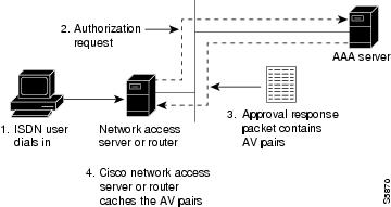
Figure 1 illustrates the request and response part of the process that happens when a user dials in, given that AAA is configured and that the AAA server has per-user configuration information for the dial-in user.
c.
d.
Note
Figure 1 Per-User Configuration Authentication and Authorization
3.
a.
b.
c.
The result of this process is a virtual access interface configured uniquely for the dial-in user.
When the user ends the call, the virtual access interface is deleted and its resources are returned for other dial-in uses.
Note
Operational Processes with IP Address Pooling
During IP Control Protocol (IPCP) address negotiation, if an IP pool name is specified for a user, the network access server checks whether the named pool is defined locally. If it is, no special action is required and the pool is consulted for an IP address.
If the required pool is not present (either in the local configuration or as a result of a previous download operation), an authorization call to obtain it is made using the special username:
pools-nas-namewhere nas-name is the configured name of the network access server. In response, the AAA server downloads the configuration of the required pool.
This pool username can be changed using Cisco IOS configuration, for example:
aaa configuration config-name nas1-pools-definition.cisco.usThis command has the effect of changing the username that is used to download the pool definitions from the default name "pools-nas-name" to "nas1-pools-definition.cisco.com."
On a TACACS+ server, the entries for an IP address pool and a user of the pool might be as follows:
user = nas1-pools {service = ppp protocol = ip {pool-def#1 = "aaa 10.0.0.1 10.0.0.3"pool-def#2 = "bbb 10.1.0.1 10.1.0.10"pool-def#3 = "ccc 10.2.0.1 10.2.0.20"pool-timeout=60}}user = georgia {login = cleartext labservice = ppp protocol = ip {addr-pool=bbb}}On a RADIUS server, the entries for the same IP address pool and user would be as follows:
nas1-pools Password = "cisco" User-Service-Type=Outbound-Usercisco-avpair = "ip:pool-def#1=aaa 10.0.0.1 10.0.0.3",cisco-avpair = "ip:pool-def#2=bbb 10.1.0.1 10.1.0.10",cisco-avpair = "ip:pool-def#3=ccc 10.2.0.1 10.2.0.20",cisco-avpair = "ip:pool-timeout=60"georgia Password = "lab"User-Service-Type = Framed-User,Framed-Protocol = PPP,cisco-avpair = "ip:addr-pool=bbb"
Note
Pools downloaded to a Cisco network access server are not retained in nonvolatile memory and automatically disappear whenever the access server or router restarts. Downloaded pools can also be made to time out automatically by adding a suitable AV pair. For more information, see the section "Supported Attrubutes for AV Pairs" and the pool-timeout attribute in Table 1. Downloaded pools are marked as dynamic in the output of the show ip local pool command.
Deleting Downloaded Pools
To delete downloaded pools, you can do either of the following:
•
Deleting a pool definition does not interrupt service for current users. If a pool is deleted and then redefined to include a pool address that is currently allocated, the new pool understands and tracks the address as expected.
•
The pool-timeout AV pair starts a timer when the pool is downloaded. Once the timer expires, the pools are deleted. The next reference to the pools again causes an authorization call to be made, and the pool definition is downloaded again. This method allows definitions to be made and changed on the AAA server and propagated to network access servers.
Supported Attributes for AV Pairs
Table 1 provides a partial list of the Cisco-specific supported attributes for AV pairs that can be used for per-user virtual interface configuration. For complete lists of Cisco-specific, vendor-specific, and TACACS+ supported attributes, see the Cisco IOS Security Configuration Guide and Cisco IOS Security Command Reference.
Table 1 Partial List of Cisco-Specific Supported AV Pair Attributes
inacl#
An input access list definition. For IP, standard or extended access list syntax can be used, although you cannot mix them within a single list. For Internet Protocol Exchange (IPX), only extended syntax is recognized. The value of this attribute is the text that comprises the body of a named access list definition.
outacl#1
An output access list definition. For IP, standard or extended access list syntax can be used. For IPX, only extended syntax is recognized. The value of this attribute is the text that comprises the body of a named access list definition.
rte-fltr-in#
An input route filter. For IP, standard or extended access list syntax can be used, although you cannot mix them within a single list. For IPX, only extended syntax is recognized. The first line of this filter must specify a routing process. Subsequent lines comprise the body of a named access list.
rte-fltr-out#
An output route filter. For IP, standard or extended access list syntax can be used, although you cannot mix them within a single list. For IPX, only extended syntax is recognized. The first line of this filter must specify a routing process. Subsequent lines comprise the body of a named access list.
route#2
Static routes, for IP and IPX.
The value is text of the form destination-address mask [gateway].
sap#
IPX static Service Advertising Protocol (SAP). The value is text from the body of an ipx sap configuration command.
sap-fltr-in#
IPX input SAP filter. Only extended access list syntax is recognized. The value is text from the body of an extended IPX access-list configuration command. (The Novell socket number for SAP filtering is 452.)
sap-fltr-out#
IPX output SAP filter. Only extended access-list command syntax is recognized. The value is text from the body of an extended IPX access-list configuration command.
pool-def#
An IP pool definition. The value is text from the body of an ip local pool configuration command.
pool-timeout
An IP pool definition. The body is an integer representing a timeout, in minutes.
1 The "outacl" attribute still exists and retains its old meaning.
2 The "route" attribute, without a trailing #, is still recognized for backward compatibility with the TACACS+ protocol specification, but if multiple static routes are required in TACACS+, full "route#" names will need to be employed.
Table 2 provides examples for each attribute on an AAA TACACS+ server.
Table 3 provides examples for each attribute on an AAA RADIUS server.
Table 3 RADIUS Server AV Pair Examples for Each Attribute
lcp:interface-config1
inacl#
outacl#
rte-fltr-in#
rte-fltr-out#
route#
sap#
sap-fltr-in#
sap-fltr-out#
pool-def#
pool-timeout
1 This attribute is specific to RADIUS servers. It can be used to add Cisco IOS interface configuration commands to specific user configuration information.
How to Configure a AAA Server for Per-User Configuration
The configuration requirements and the structure of per-user configuration information is set by the specifications of each type of AAA server. Refer to your server documentation for more detailed information. The following sections about TACACS and RADIUS servers are specific to per-user configuration:
•
•
•
See the section "Monitoring and Debugging Per-User Configuration Settings" later in this chapter for tips on troubleshooting per-user configuration settings. See the section "Configuration Examples for Per-User Configuration" at the end of this chapter for examples of configuring RADIUS and TACACS servers.
Configuring a Freeware TACACS Server for Per-User Configuration
On a TACACS server, the entry in the user file takes a standard form. In the freeware version of TACACS+, the following lines appear in order:
•
•
•
•
•
The general form of a freeware TACACS user entry is shown in the following example:
user = username {authentication parameters go hereauthorization parameters go here}The freeware TACACS user entry form is also shown by the following examples for specific users:
user= Router1Password= cleartext welcomeService= PPP protocol= ip {ip:route=10.0.0.0 255.0.0.0ip:route=10.1.0.0 255.0.0.0ip:route=10.2.0.0 255.0.0.0ip:inacl#5=deny 10.5.0.1}user= Router2Password= cleartext labService= PPP protocol= ip {ip:addr-pool=bbb}For more requirements and detailed information, refer to your AAA server documentation.
Configuring a CiscoSecure TACACS Server for Per-User Configuration
The format of an entry in the user file in the AAA database is generally name = value. Some values allow additional subparameters to be specified and, in these cases, the subparameters are enclosed in braces ({}). The following simple example depicts an AAA database showing the default user, one group, two users that belong to the group, and one user that does not:
# Sample AA Database 1unknown_user = {password = system #Use the system's password file (/etc/passwd)}group = staff {# Password for staff who do not have their own.password = des "sefjkAlM7zybE"service = shell {# Allow any commands with any attributes.default cmd = permitdefault attribute = permit}}user = joe { # joe uses the group password.member = "staff"}user = pete { # pete has his own password.member = "staff"password = des "alkd9Ujiqp2y"}user = anita {# Use the "default" user password mechanism defined above.service = shell {cmd = telnet { # Allow Telnet to any destination}}}For more information about the requirements and details of configuring the CiscoSecure server, see the CiscoSecure UNIX Server User Guide.
Configuring a RADIUS Server for Per-User Configuration
On a RADIUS server, the format of an entry in the users file includes the following lines in order:
•
•
•
•
Note
The structure of an AV pair for Cisco platforms starts with cisco-avpair followed by a space, an equal sign, and another space. The rest of the line is within double quotation marks and, for all lines but the last, ends with a comma. Inside the double quotation marks is a phrase indicating the supported attribute, another equal sign, and a Cisco IOS command. The following examples show two different partial user configurations on a RADIUS server.
Router1
Password = "welcome"User-Service-Type = Framed-User,Framed-Protocol = PPP,cisco-avpair = "ip:route=10.0.0.0 255.0.0.0",cisco-avpair = "ip:route=10.1.0.0 255.0.0.0",cisco-avpair = "ip:route=10.2.0.0 255.0.0.0",cisco-avpair = "ip:inacl#5=deny 10.5.0.1"Router2
Password = "lab"User-Service-Type = Framed-User,Framed-Protocol = PPP,cisco-avpair = "ip:addr-pool=bbb"Monitoring and Debugging Per-User Configuration Settings
Per-user configuration information exists on AAA servers only and is configured there, as described in the "How to Configure a AAA Server for Per-User Configuration" section.
For more information about configuring an application that can tie AAA per-user configuration information to generic interface and router configuration, see the chapter "Configuring Virtual Profiles" in this publication. Virtual profiles are required for combining per-user configuration information and generic interface and router configuration information to create virtual access interfaces for individual ISDN B channels.
However, you can monitor and debug the per-user configuration settings on the router or access server that are set from an AAA server. Table 4 indicates some of the commands to use for each attribute.
Configuration Examples for Per-User Configuration
The following sections provide two comprehensive examples:
These examples show router or access server configuration and AV pair configuration on an AAA server.
TACACS+ Freeware Examples
This section provides the TACACS+ freeware versions of the following examples:
•
•
IP Access Lists and Static Routes Using Virtual Profiles over ISDN BRI
The following example provides configurations for the TACACS+ freeware daemon, the network access server, and the peer router named Router1. On the TACACS+ AAA server, peer router Router1 has a configuration that includes static routes and IP access lists.
TACACS+ Freeware Daemon Configuration File
key = tac123user = Router1 {global = cleartext welcomeservice = ppp protocol = ip {route#1="10.0.0.0 255.0.0.0"route#2="10.1.0.0 255.0.0.0"route#3="10.2.0.0 255.0.0.0"inacl#1="deny 10.5.0.1"}}Current Network Access Server Configuration
version 11.3service timestamps debug datetime localtimeservice udp-small-serversservice tcp-small-servers!hostname Router2!aaa new-modelaaa authentication ppp default tacacs+aaa authorization network tacacs+enable secret 5 $1$koOn$/1QAylov6JFAElxRCrL.o/enable password lab!username Router1 password 7 15050E0007252621ip host Router2 172.21.114.132ip domain-name cisco.comip name-server 172.19.2.132ip name-server 192.168.30.32isdn switch-type basic-5essinterface Ethernet 0ip address 172.21.114.132 255.255.255.224no ip mroute-cachemedia-type 10BaseT!interface Virtual-Template1ip unnumbered Ethernet0no cdp enable!!interface BRI0ip unnumbered Ethernet0no ip mroute-cacheencapsulation pppno ip route-cachedialer idle-timeout 300dialer map ip 10.5.0.1 name Router1 broadcast 61482dialer-group 1no fair-queueppp authentication chap!!ip default-gateway 172.21.114.129no ip classlessip route 0.0.0.0 0.0.0.0 172.21.114.129!virtual-profile virtual-template 1dialer-list 1 protocol ip permittacacs-server host 172.21.114.130tacacs-server key tac123Current Peer Configuration for Router1
version 11.3no service pad!hostname Router1!enable secret 5 $1$m1WK$RsjborN1Z.XZuFqsrtSnp/enable password lab!username Router2 password 7 051C03032243430Cip host Router1 172.21.114.134ip domain-name cisco.comip name-server 172.19.2.132ip name-server 192.168.30.32isdn switch-type basic-5ess!interface Ethernet0ip address 172.21.114.134 255.255.255.224no ip route-cacheshutdown!interface BRI0ip address 10.5.0.1 255.0.0.0encapsulation pppdialer map ip 172.21.114.132 name Router2 broadcast 61483dialer-group 1no fair-queue!ip default-gateway 172.21.114.129no ip classlessip route 172.21.0.0 255.255.0.0 BRI0dialer-list 1 protocol ip permit!line con 0exec-timeout 0 0line vty 0 4password labloginendIPX Per-User SAP Filters Using IPXWAN and Virtual Profiles by a Synchronous Interface
The following example provides configurations for the TACACS+ daemon and the peer router named Router1. On the TACACS+ AAA server, user ny has a configuration that includes inbound and outbound SAP filters.
TACACS+ Freeware Daemon Configuration File for User
key = tac123user = Router1 {global = cleartext welcomeservice = ppp protocol = ipx {sap="101 CYBER-01 40.0000.0000.0001 400 10"sap="202 CYBER-02 40.0000.0000.0001 401 10"sap="303 CYBER-03 40.0000.0000.0001 402 10"sap-fltr-out#1="deny 40 101"sap-fltr-out#2="deny 40 202"sap-fltr-out#3="permit -1"sap-fltr-in#1="permit 30 444"sap-fltr-in#2="deny -1"Current Remote Peer (Router1) Configuration
version 11.3!hostname Router1!enable password lab!username Router2 password 7 140017070F0B272Eip host Router1 172.21.114.131ip name-server 172.19.2.132ip name-server 192.168.30.32ipx routing 0000.0c47.090dipx internal-network 30!interface Ethernet0ip address 172.21.114.131 255.255.255.224!interface Serial1no ip addressencapsulation pppipx ipxwan 0 unnumbered peer-Router1clockrate 4000000!ipx sap 444 ZEON-4 30.0000.0000.0001 444 10ipx sap 555 ZEON-5 30.0000.0000.0001 555 10ipx sap 666 ZEON-6 30.0000.0000.0001 666 10!Current Network Access Server (Router2) Configurationversion 11.3service timestamps debug uptime!hostname Router2!aaa new-modelaaa authentication ppp default tacacs+aaa authorization network tacacs+enable password lab!username Router1 password 7 044C0E0A0C2E414Bip host LA 172.21.114.133ip name-server 192.168.30.32ip name-server 172.19.2.132ipx routing 0000.0c47.12d3ipx internal-network 40!interface Ethernet0ip address 172.21.114.133 255.255.255.224!interface Virtual-Template1no ip addressipx ipxwan 0 unnumbered nas-Router2no cdp enable!interface Serial1ip unnumbered Ethernet0encapsulation pppipx ipxwan 0 unnumbered nas-Router2ppp authentication chap!ipx sap 333 DEEP9 40.0000.0000.0001 999 10!virtual-profile virtual-template 1tacacs-server host 172.21.114.130tacacs-server key tac123RADIUS Examples
This section provides the RADIUS versions of the following examples:
•
•
IP Access Lists and Static Routes Using Virtual Profiles over ISDN BRI
The following example shows a remote peer (Router1) configured to dial in to a BRI on a Cisco network access server (Router2), which requests user configuration information from an AAA server (radiusd):
RADIUS User File (Router1)
Password = "welcome"User-Service-Type = Framed-User,Framed-Protocol = PPP,cisco-avpair = "ip:route=10.1.0.0 255.0.0.0",cisco-avpair = "ip:route=10.2.0.0 255.0.0.0",cisco-avpair = "ip:route=10.3.0.0 255.0.0.0",cisco-avpair = "ip:inacl#5=deny 10.0.0.1"Current Network Access Server Configuration
version 11.3service timestamps debug datetime localtimeservice udp-small-serversservice tcp-small-servers!hostname Router2!aaa new-modelaaa authentication ppp default radiusaaa authorization network radiusenable secret 5 $1$koOn$/1QAylov6JFAElxRCrL.o/enable password lab!username Router1 password 7 15050E0007252621ip host Router2 172.21.114.132ip domain-name cisco.comip name-server 172.19.2.132ip name-server 192.168.30.32isdn switch-type basic-5essinterface Ethernet0ip address 172.21.114.132 255.255.255.224no ip mroute-cachemedia-type 10BaseT!interface Virtual-Template1ip unnumbered Ethernet0no cdp enable!interface BRI0ip unnumbered Ethernet0no ip mroute-cacheencapsulation pppno ip route-cachedialer idle-timeout 300dialer map ip 10.5.0.1 name Router1 broadcast 61482dialer-group 1no fair-queueppp authentication chap!ip default-gateway 172.21.114.129no ip classlessip route 0.0.0.0 0.0.0.0 172.21.114.129!virtual-profile vtemplate 1dialer-list 1 protocol ip permitradius-server host 172.21.114.130radius-server key rad123Current Peer Configuration for Router1
version 11.3no service pad!hostname Router1!enable secret 5 $1$m1WK$RsjborN1Z.XZuFqsrtSnp/enable password lab!username Router2 password 7 051C03032243430Cip host Router1 172.21.114.134ip domain-name cisco.comip name-server 172.19.2.132ip name-server 192.168.30.32isdn switch-type basic-5ess!interface Ethernet0ip address 172.21.114.134 255.255.255.224no ip route-cacheshutdown!interface BRI0ip address 10.5.0.1 255.0.0.0encapsulation pppdialer map ip 172.21.114.132 name Router2 broadcast 61483dialer-group 1no fair-queue!ip default-gateway 172.21.114.129no ip classlessip route 172.21.0.0 255.255.0.0 BRI0dialer-list 1 protocol ip permit!line con 0exec-timeout 0 0line vty 0 4password lablogin!endOutput of ping Command from Router1
Router1# ping 172.21.114.132Type escape sequence to abort.Sending 5, 100-byte ICMP Echos to 172.21.114.132, timeout is 2 seconds:U.U.USuccess rate is 0 percent (0/5)(fails due to access list deny)RADIUS Debug Output
radrecv: Request from host ac157284 code=1, id=46, length=67Client-Id = 172.21.114.132Client-Port-Id = 1112670208User-Name = "Router1"CHAP-Password = "\037\317\213\326*\236)#+\266\243\255x\331\370v\334"User-Service-Type = Framed-UserFramed-Protocol = PPPSending Ack of id 46 to ac157284 (172.21.114.132)User-Service-Type = Framed-UserFramed-Protocol = PPP[Vendor 9] cisco-avpair = "ip:route=10.0.0.0 255.0.0.0"[Vendor 9] cisco-avpair = "ip:route=10.1.0.0 255.0.0.0"[Vendor 9] cisco-avpair = "ip:route=10.2.0.0 255.0.0.0"[Vendor 9] cisco-avpair = "ip:inacl#5=deny 10.0.0.1"Network Access Server (Router2) show and debug Command Output
Router2# show debugGeneral OS:AAA Authorization debugging is onPPP:PPP authentication debugging is onMultilink activity debugging is onISDN:ISDN events debugging is onDial on demand:Dial on demand events debugging is onVTEMPLATE:Virtual Template debugging is onpr 4 08:30:09: ISDN BR0: received HOST_INCOMING_CALLBearer Capability i = 0x080010*Apr 4 08:30:09: -------------------Channel ID i = 0x0101*Apr 4 08:30:09: IE out of order or end of `private' IEs --Bearer Capability i = 0x8890*Apr 4 08:30:09: Channel ID i = 0x89*Apr 4 08:30:09: Called Party Number i = 0xC1, `61483'*Apr 4 08:30:09: ISDN BR0: Event: Received a call from <unknown> on B1 at 64 Kb/s*Apr 4 08:30:09: ISDN BR0: Event: Accepting the call%LINK-3-UPDOWN: Interface BRI0:1, changed state to up*Apr 4 08:30:09: ISDN BR0: received HOST_CONNECTChannel ID i = 0x0101*Apr 4 08:30:09: -------------------Channel ID i = 0x89*Apr 4 08:30:09: ISDN BR0: Event: Connected to <unknown> on B1 at 64 Kb/s*Apr 4 08:30:09: PPP BRI0:1: Send CHAP challenge id=30 to remote*Apr 4 08:30:10: PPP BRI0:1: CHAP response received from Router1*Apr 4 08:30:10: PPP BRI0:1: CHAP response id=30 received from Router1*Apr 4 08:30:10: AAA/AUTHOR/LCP: authorize LCP*Apr 4 08:30:10: AAA/AUTHOR/LCP: BRI0:1: (0): user='Router1'*Apr 4 08:30:10: AAA/AUTHOR/LCP: BRI0:1: (0): send AV service=ppp*Apr 4 08:30:10: AAA/AUTHOR/LCP: BRI0:1: (0): send AV protocol=lcp*Apr 4 08:30:10: AAA/AUTHOR/LCP: BRI0:1: (2084553184): Method=RADIUS*Apr 4 08:30:10: AAA/AUTHOR (2084553184): Post authorization status = PASS_ADD*Apr 4 08:30:10: PPP BRI0:1: Send CHAP success id=30 to remote*Apr 4 08:30:10: PPP BRI0:1: remote passed CHAP authentication.*Apr 4 08:30:10: VTEMPLATE Reuse vaccess1, New Recycle queue size:0*Apr 4 08:30:10: VTEMPLATE set default vaccess1 with no ip address*Apr 4 08:30:10: Virtual-Access1 VTEMPLATE hardware address 0000.0c46.154a*Apr 4 08:30:10: VTEMPLATE vaccess1 has a new cloneblk vtemplate, now it has vtemplate*Apr 4 08:30:10: VTEMPLATE undo default settings vaccess1*Apr 4 08:30:10: VTEMPLATE ************* CLONE VACCESS1 ******************Apr 4 08:30:10: VTEMPLATE Clone from vtemplate1 to vaccess1interface Virtual-Access1no ip addressencap pppip unnumbered ethernet 0end%LINK-3-UPDOWN: Interface Virtual-Access1, changed state to up*Apr 4 08:30:10: AAA/AUTHOR/LCP: authorize LCP*Apr 4 08:30:10: AAA/AUTHOR/LCP: Virtual-Access1: (0): user='Router1'*Apr 4 08:30:10: AAA/AUTHOR/LCP: Virtual-Access1: (0): send AV service=ppp*Apr 4 08:30:10: AAA/AUTHOR/LCP: Virtual-Access1: (0): send AV protocol=lcp*Apr 4 08:30:10: AAA/AUTHOR/LCP: Virtual-Access1: (1338953760): Method=RADIUS*Apr 4 08:30:10: AAA/AUTHOR (1338953760): Post authorization status = PASS_ADD*Apr 4 08:30:10: AAA/AUTHOR/FSM: Virtual-Access1: (0): can we start IPCP?*Apr 4 08:30:10: AAA/AUTHOR/FSM: Virtual-Access1: (0): user='Router1'*Apr 4 08:30:10: AAA/AUTHOR/FSM: Virtual-Access1: (0): send AV service=ppp*Apr 4 08:30:10: AAA/AUTHOR/FSM: Virtual-Access1: (0): send AV protocol=ip*Apr 4 08:30:10: AAA/AUTHOR/FSM: Virtual-Access1: (1716082074): Method=RADIUS*Apr 4 08:30:10: AAA/AUTHOR (1716082074): Post authorization status = PASS_ADD*Apr 4 08:30:10: AAA/AUTHOR/FSM: Virtual-Access1: we can start IPCP (0x8021)*Apr 4 08:30:10: MLP Bad link Virtual-Access1*Apr 4 08:30:10: AAA/AUTHOR/FSM: Virtual-Access1: (0): can we start UNKNOWN?*Apr 4 08:30:10: AAA/AUTHOR/FSM: Virtual-Access1: (0): user='Router1'*Apr 4 08:30:10: AAA/AUTHOR/FSM: Virtual-Access1: (0): send AV service=ppp*Apr 4 08:30:10: AAA/AUTHOR/FSM: Virtual-Access1: (0): send AV protocol=unknown*Apr 4 08:30:10: AAA/AUTHOR/FSM: Virtual-Access1: (2526612868): Method=RADIUS*Apr 4 08:30:10: AAA/AUTHOR (2526612868): Post authorization status = PASS_ADD*Apr 4 08:30:10: AAA/AUTHOR/FSM: Virtual-Access1: we can start UNKNOWN (0x8207)*Apr 4 08:30:10: MLP Bad link Virtual-Access1*Apr 4 08:30:10: BRI0:1: Vaccess started from dialer_remote_name*Apr 4 08:30:10: AAA/AUTHOR/FSM: BRI0:1: (0): can we start IPCP?*Apr 4 08:30:10: AAA/AUTHOR/FSM: BRI0:1: (0): user='Router1'*Apr 4 08:30:10: AAA/AUTHOR/FSM: BRI0:1: (0): send AV service=ppp*Apr 4 08:30:10: AAA/AUTHOR/FSM: BRI0:1: (0): send AV protocol=ip*Apr 4 08:30:10: AAA/AUTHOR/FSM: BRI0:1: (3920403585): Method=RADIUS*Apr 4 08:30:10: AAA/AUTHOR (3920403585): Post authorization status = PASS_ADD*Apr 4 08:30:10: AAA/AUTHOR/FSM: BRI0:1: we can start IPCP (0x8021)*Apr 4 08:30:10: AAA/AUTHOR/FSM: BRI0:1: (0): can we start UNKNOWN?*Apr 4 08:30:10: AAA/AUTHOR/FSM: BRI0:1: (0): user='Router1'*Apr 4 08:30:10: AAA/AUTHOR/FSM: BRI0:1: (0): send AV service=ppp*Apr 4 08:30:10: AAA/AUTHOR/FSM: BRI0:1: (0): send AV protocol=unknown*Apr 4 08:30:10: AAA/AUTHOR/FSM: BRI0:1: (3439943223): Method=RADIUS*Apr 4 08:30:10: AAA/AUTHOR (3439943223): Post authorization status = PASS_ADD*Apr 4 08:30:10: AAA/AUTHOR/FSM: BRI0:1: we can start UNKNOWN (0x8207)%LINEPROTO-5-UPDOWN: Line protocol on Interface BRI0:1, changed state to up%LINEPROTO-5-UPDOWN: Line protocol on Interface Virtual-Access1, changed state to up*Apr 4 08:30:13: AAA/AUTHOR/IPCP: Virtual-Access1: start: her address 10.0.0.1, we want 0.0.0.0*Apr 4 08:30:13: AAA/AUTHOR/IPCP: Virtual-Access1: (0): user='Router1'*Apr 4 08:30:13: AAA/AUTHOR/IPCP: Virtual-Access1: (0): send AV servi*Apr 4 08:30:13: AAA/AUTHOR/IPCP: Virtual-Access1: (0): send AV service=ppp*Apr 4 08:30:13: AAA/AUTHOR/IPCP: Virtual-Access1: (0): send AV protocol=ip*Apr 4 08:30:13: AAA/AUTHOR/IPCP: Virtual-Access1: (0): send AV addr*10.0.0.1*Apr 4 08:30:13: AAA/AUTHOR/IPCP: Virtual-Access1: (3215797579): Method=RADIUS*Apr 4 08:30:13: AAA/AUTHOR (3215797579): Post authorization status = PASS_ADD*Apr 4 08:30:13: AAA/AUTHOR/IPCP: Virtual-Access1: Processing AV service=ppp*Apr 4 08:30:13: AAA/AUTHOR/IPCP: Virtual-Access1: Processing AV protocol=ip*Apr 4 08:30:13: AAA/AUTHOR/IPCP: Virtual-Access1: Processing AV addr*10.0.0.1*Apr 4 08:30:13: AAA/AUTHOR/IPCP: Virtual-Access1: Processing AV route=10.1.0.0 255.0.0.0*Apr 4 08:30:13: AAA/AUTHOR/IPCP: Virtual-Access1: Processing AV route=10.2.0.0 255.0.0.0*Apr 4 08:30:13: AAA/AUTHOR/IPCP: Virtual-Access1: Processing AV route=10.3.0.0 255.0.0.0*Apr 4 08:30:13: AAA/AUTHOR/IPCP: Virtual-Access1: Processing AV inacl#5=deny 10.0.0.1*Apr 4 08:30:13: AAA/AUTHOR/IPCP: Virtual-Access1: authorization succeeded*Apr 4 08:30:13: AAA/AUTHOR/IPCP: Virtual-Access1: done: her address 10.0.0.1, we want 10.0.0.1*Apr 4 08:30:13: AAA/AUTHOR/IPCP: Virtual-Access1: authorization succeeded*Apr 4 08:30:13: AAA/AUTHOR: Virtual-Access1: parse_cmd `ip route 10.0.0.0 255.0.0.0 10.0.0.1' ok (0)*Apr 4 08:30:13: AAA/AUTHOR: Virtual-Access1: enqueue peruser IP txt=no ip route 10.0.0.0 255.0.0.0 10.0.0.1*Apr 4 08:30:13: AAA/AUTHOR: Virtual-Access1: parse_cmd `ip route 11.0.0.0 255.0.0.0 10.0.0.1' ok (0)*Apr 4 08:30:13: AAA/AUTHOR: Virtual-Access1: enqueue peruser IP txt=no ip route 11.0.0.0 255.0.0.0 10.0.0.1*Apr 4 08:30:13: AAA/AUTHOR: Virtual-Access1: parse_cmd `ip route 12.0.0.0 255.0.0.0 10.0.0.1' ok (0)*Apr 4 08:30:13: AAA/AUTHOR: Virtual-Access1: enqueue peruser IP txt=no ip route 12.0.0.0 255.0.0.0 10.0.0.1*Apr 4 08:30:13: AAA/AUTHOR: parse `ip access-list standard Virtual-Access1#1' ok (0)*Apr 4 08:30:13: AAA/AUTHOR: parse `deny 10.0.0.1' ok (0)*Apr 4 08:30:13: AAA/AUTHOR: Virtual-Access1: enqueue peruser IP txt=no ip access-list standard Virtual-Access1#1*Apr 4 08:30:13: VTEMPLATE vaccess1 has a new cloneblk AAA, now it has vtemplate/AAA*Apr 4 08:30:13: VTEMPLATE ************* CLONE VACCESS1 ******************Apr 4 08:30:13: VTEMPLATE Clone from AAA to vaccess1interface Virtual-Access1ip access-group Virtual-Access1#1 in*Apr 4 08:30:13: AAA/AUTHOR: Virtual-Access1: vaccess parse `interface Virtual-Access1ip access-group Virtual-Access1#1 in` ok (0)*Apr 4 08:30:13: AAA/AUTHOR/FSM: Check for unauthorized mandatory AV's*Apr 4 08:30:13: AAA/AUTHOR/FSM: Processing AV service=ppp*Apr 4 08:30:13: AAA/AUTHOR/FSM: Processing AV protocol=unknown*Apr 4 08:30:13: AAA/AUTHOR/FSM: succeeded%ISDN-6-CONNECT: Interface BRI0:1 is now connected to Router1Router2# show ip access-listStandard IP access list Virtual-Access1#1 (per-user)deny 10.0.0.1Router2# show ip routeCodes: C - connected, S - static, I - IGRP, R - RIP, M - mobile, B - BGPD - EIGRP, EX - EIGRP external, O - OSPF, IA - OSPF inter areaN1 - OSPF NSSA external type 1, N2 - OSPF NSSA external type 2E1 - OSPF external type 1, E2 - OSPF external type 2, E - EGPi - IS-IS, L1 - IS-IS level-1, L2 - IS-IS level-2, * - candidate defaultU - per-user static route, o - ODRGateway of last resort is 172.21.114.129 to network 0.0.0.0U 10.0.0.0/8 [1/0] via 10.3.0.1U 10.1.0.0/8 [1/0] via 10.3.0.1U 10.2.0.0/8 [1/0] via 10.3.0.110.3.0.0/8 is subnetted, 1 subnetsC 10.3.0.1 is directly connected, Virtual-Access1172.21.0.0/16 is subnetted, 1 subnetsC 172.21.114.128 is directly connected, Ethernet0S* 0.0.0.0/0 [1/0] via 172.21.114.129Router2# show interfaces virtual-access 1Virtual-Access1 is up, line protocol is upHardware is Virtual Access interfaceInterface is unnumbered. Using address of Ethernet0 (172.21.114.132)MTU 1500 bytes, BW 64 Kbit, DLY 100000 usec, rely 255/255, load 1/255Encapsulation PPP, loopback not set, keepalive set (10 sec)DTR is pulsed for 5 seconds on resetLCP Open, multilink ClosedOpen: IPCP, CDPLast input 5d04h, output never, output hang neverLast clearing of "show interface" counters 00:06:42Queueing strategy: fifoOutput queue 0/40, 0 drops; input queue 0/75, 0 drops5 minute input rate 0 bits/sec, 0 packets/sec5 minute output rate 0 bits/sec, 0 packets/sec76 packets input, 3658 bytes, 0 no bufferReceived 0 broadcasts, 0 runts, 0 giants0 input errors, 0 CRC, 0 frame, 0 overrun, 0 ignored, 0 abort141 packets output, 2909 bytes, 0 underruns0 output errors, 0 collisions, 0 interface resets0 output buffer failures, 0 output buffers swapped out0 carrier transitionsRouter2# show ip interface virtual-access 1Virtual-Access1 is up, line protocol is upInterface is unnumbered. Using address of Ethernet0 (172.21.114.132)Broadcast address is 255.255.255.255Peer address is 10.0.0.1MTU is 1500 bytesHelper address is not setDirected broadcast forwarding is enabledOutgoing access list is not setInbound access list is Virtual-Access1#1Proxy ARP is enabledSecurity level is defaultSplit horizon is enabledICMP redirects are always sentICMP unreachables are always sentICMP mask replies are never sentIP fast switching is disabledRouter2# debug ip packetIP packet debugging is onRouter2#*Apr 4 08:30:42: IP: s=172.21.114.129 (Ethernet0), d=255.255.255.255, len 186, rcvd 2*Apr 4 08:30:42: IP: s=10.0.0.1 (Virtual-Access1), d=172.21.114.132, len 104, a*Apr 4 08:30:42: IP: s=10.0.0.1 (Virtual-Access1), d=172.21.114.132, len 104, access denied*Apr 4 08:30:42: IP: s=172.21.114.132 (local), d=10.0.0.1 (Virtual-Access1), len 4, sending*Apr 4 08:30:42: IP: s=10.0.0.1 (Virtual-Access1), d=172.21.114.132, len 104, access denied*Apr 4 08:30:44: IP: s=10.0.0.1 (Virtual-Access1), d=172.21.114.132, len 104, access denied*Apr 4 08:30:44: IP: s=172.21.114.132 (local), d=10.0.0.1 (Virtual-Access1), len 16, sending*Apr 4 08:30:44: IP: s=10.0.0.1 (Virtual-Access1), d=172.21.114.132, len 104, access deniedIPX Per-User SAP Filters Using IPXWAN and Virtual Profiles by a Synchronous Interface
The following examples show a remote peer (Router1) configured to dial in to a synchronous interface on a Cisco network access server (Router2), which requests user configuration information from an AAA server (radiusd):
RADIUS User File (Router 1)
Password = "welcome"User-Service-Type = Framed-User,Framed-Protocol = PPP,cisco-avpair = "ipx:sap=101 CYBER-01 40.0000.0000.0001 400 10",cisco-avpair = "ipx:sap=202 CYBER-02 40.0000.0000.0001 401 10",cisco-avpair = "ipx:sap=303 CYBER-03 40.0000.0000.0001 402 10",cisco-avpair = "ipx:sap-fltr-out#20=deny 40 101",cisco-avpair = "ipx:sap-fltr-out#21=deny 40 202",cisco-avpair = "ipx:sap-fltr-out#22=permit -1",cisco-avpair = "ipx:sap-fltr-in#23=permit 30 444",cisco-avpair = "ipx:sap-fltr-in#23=deny -1"Current Remote Peer (Router 1) Configuration
hostname Router1!enable password lab!username Router2 password 7 140017070F0B272Eip host Router1 172.21.114.131ip name-server 172.19.2.132ip name-server 192.168.30.32ipx routing 0000.0c47.090dipx internal-network 30!interface Ethernet0ip address 172.21.114.131 255.255.255.224!interface Serial1no ip addressencapsulation pppipx ipxwan 0 unnumbered peer-Router1clockrate 4000000!ipx sap 444 ZEON-4 30.0000.0000.0001 444 10ipx sap 555 ZEON-5 30.0000.0000.0001 555 10ipx sap 666 ZEON-6 30.0000.0000.0001 666 10!...version 12.1service timestamps debug uptime!hostname Router2!aaa new-modelaaa authentication ppp default radiusaaa authorization network radiusenable password lab!username Router1 password 7 044C0E0A0C2E414Bip host Router2 172.21.114.133ip name-server 172.22.30.32ip name-server 192.168.2.132ipx routing 0000.0c47.12d3ipx internal-network 40!interface Ethernet0ip address 172.21.114.133 255.255.255.224!interface Virtual-Template1no ip addressipx ipxwan 0 unnumbered nas-Router2no cdp enable!interface Serial1ip unnumbered Ethernet0encapsulation pppipx ipxwan 0 unnumbered nas-Router2ppp authentication chap!ipx sap 333 DEEP9 40.0000.0000.0001 999 10!virtual-profile vtemplate 1radius-server host 172.21.114.130radius-server key rad123RADIUS debug Output
radrecv: Request from host ac157285 code=1, id=23, length=67Client-Id = 172.21.114.133Client-Port-Id = 1399128065User-Name = "Router1"CHAP-Password = "%"(\012I$\262\352\031\276\024\302\277\225\347z\274"User-Service-Type = Framed-UserFramed-Protocol = PPPSending Ack of id 23 to ac157285 (172.21.114.133)User-Service-Type = Framed-UserFramed-Protocol = PPP[Vendor 9] cisco-avpair = "ipx:sap=101 CYBER-01 40.0000.0000.0001 400 10"[Vendor 9] cisco-avpair = "ipx:sap=202 CYBER-02 40.0000.0000.0001 401 10"[Vendor 9] cisco-avpair = "ipx:sap=303 CYBER-03 40.0000.0000.0001 402 10"[Vendor 9] cisco-avpair = "ipx:sap-fltr-out#20=deny1 40 101"[Vendor 9] cisco-avpair = "ipx:sap-fltr-out#21=deny 40 202"[Vendor 9] cisco-avpair = "ipx:sap-fltr-out#22=permit -1"[Vendor 9] cisco-avpair = "ipx:sap-fltr-in#23=permit 30 444"[Vendor 9] cisco-avpair = "ipx:sap-fltr-in#23=deny -1"Network Access Server show Command Output
Router2# show ipx serversCodes: S - Static, P - Periodic, E - EIGRP, N - NLSP, H - Holddown, + = detail5 Total IPX ServersTable ordering is based on routing and server infoType Name Net Address Port Route Hops Itfs 101 CYBER-01 40.0000.0000.0001:0400 conn 10 Ints 202 CYBER-02 40.0000.0000.0001:0401 conn 10 Ints 303 CYBER-03 40.0000.0000.0001:0402 conn 10 IntS 333 DEEP9 40.0000.0000.0001:0999 conn 10 IntP 444 ZEON-4 30.0000.0000.0001:0444 7/01 11 Vi1Router1# show ipx serversCodes: S - Static, P - Periodic, E - EIGRP, N - NLSP, H - Holddown, + = detail5 Total IPX ServersTable ordering is based on routing and server infoType Name Net Address Port Route Hops ItfP 303 CYBER-03 40.0000.0000.0001:0402 7/01 11 Se1P 333 DEEP9 40.0000.0000.0001:0999 7/01 11 Se1S 444 ZEON-4 30.0000.0000.0001:0444 conn 10 IntS 555 ZEON-5 30.0000.0000.0001:0555 conn 10 IntS 666 ZEON-6 30.0000.0000.0001:0666 conn 10 IntRouter2# show ipx access-listIPX sap access list Virtual-Access1#2Cisco and the Cisco Logo are trademarks of Cisco Systems, Inc. and/or its affiliates in the U.S. and other countries. A listing of Cisco's trademarks can be found at www.cisco.com/go/trademarks. Third party trademarks mentioned are the property of their respective owners. The use of the word partner does not imply a partnership relationship between Cisco and any other company. (1005R)
Any Internet Protocol (IP) addresses and phone numbers used in this document are not intended to be actual addresses and phone numbers. Any
examples, command display output, network topology diagrams, and other figures included in the document are shown for illustrative purposes
only. Any use of actual IP addresses or phone numbers in illustrative content is unintentional and coincidental.

© 2001-2009 Cisco Systems, Inc. All rights reserved.