-
Dial Configuration Guide, Cisco IOS Release 15M&T
- Part 1: Dial Interfaces, Controllers, and Lines
-
Part 2: Modem Configuration and Management
-
Overview of Modem Interfaces
-
Configuring and Managing Integrated Modems
-
1- and 2-Port V.90 Modem WICs for Cisco 2600 and Cisco 3600 Series Multiservice Platforms
-
Call Tracker show Commands Extensions
-
Cisco NM-8AM-V2 and NM-16AM-V2 Analog Modem Network Modules with V.92
-
MICA and NextPort Modem Tech-Support Command Additions
-
PIAFS Wireless Data Protocol Version 2.1 for Cisco MICA Modems
-
V.92 and V.44 Support for Digital Modems
-
V.92 Modem on Hold for Cisco AS5300 and Cisco AS5800 Universal Access Servers
-
V.92 Modem on Hold for Cisco AS5350, Cisco AS5400, and Cisco AS5850 Universal Gateways and Cisco AS5800 Universal Access Servers
-
V.92 Quick Connect for Cisco AS5300 and Cisco AS5800 Universal Access Servers
-
V.92 Quick Connect for Cisco AS5350, Cisco AS5400, and Cisco AS5850 Universal Gateways and Cisco AS5800 Universal Access Servers
-
V.92 Reporting Using RADIUS Attribute v.92-info
-
Configuring and Managing Cisco Access Servers and Dial Shelves
-
Configuring and Managing External Modems
-
Modem Signal and Line States
-
Creating and Using Modem Chat Scripts
-
Cisco Modem User Interface
-
Modem Script and System Script Support in Large-Scale Dial-Out
-
-
Part 3: ISDN Configuration
-
Configuring ISDN BRI
-
Leased and Switched BRI Interface for ETSI NET3
-
ISDN BCAC and Round-Robin Channel Selection Enhancements
-
Configuring Virtual Asynchronous Traffic over ISDN
-
Configuring Modem Use over ISDN BRI
-
Configuring X.25 on ISDN
-
Configuring X.25 on ISDN Using AO/DI
-
Configuring ISDN on Cisco 800 Series Routers
-
- Part 4: Signaling Configuration
-
Part 5: Dial-on-Demand Routing Configuration
-
Preparing to Configure DDR
-
Configuring Legacy DDR Spokes
-
Configuring Legacy DDR Hubs
-
Configuring Peer-to-Peer DDR with Dialer Profiles
-
Dialer Map VRF-Aware for an MPLS VPN
-
Dialer Persistent
-
PPPoE Client DDR Idle-Timer
-
Redial Enhancements
-
Rotating Through Dial Strings
-
Configuring Dialer CEF
-
CEF Support for Dialer Profiles on Cisco 7500 Routers
-
IPv6 Cisco Express Forwarding Switching on Dialer Interfaces
-
Configuring Snapshot Routing
-
- Part 6: Dial-Backup Configuration
- Part 7: Dial-Related Addressing Services
- Part 8: Virtual Templates and Profiles
-
Part 9: PPP Configuration
-
Configuring Asynchronous SLIP and PPP
-
Optimized PPP Negotiation
-
Customer Profile Idle Timer Enhancements for Interesting Traffic
-
Multilink PPP Minimum Links Mandatory
-
Configuring Media-Independent PPP and Multilink PPP
-
PPP/MLP MRRU Negotiation Configuration
-
Troubleshooting Enhancements for Multilink PPP over ATM Link Fragmentation and Interleaving
-
Multichassis Multilink PPP
-
- Part 10: Callback and Bandwidth Allocation Configuration
- Configuring Large-Scale Dial-Out
- Part 11: Dial Access Specialized Features
- Part 12: Dial Access Scenarios
 Feedback
Table Of Contents
Dial-Out DS0 Level Trunk Group
Prerequisites for Dial-Out DS0 Level Trunk Groups
Restrictions for Dial-Out DS0 Level Trunk Groups
Information About Dial-Out DS0 Level Trunk Groups
Dial-Out DS0 Level Trunk Group Outbound Call Control
Dial-Out DS0 Level Trunk Group Aggregation Requirement
Structure and Relationship of a Dial-Out DS0 Level Trunk Group
How to Configure Dial-Out DS0 Level Trunk Groups and Enable for DDR
Configuring Dial-Out DS0 Level Trunk Groups on a DS1 Configured for CAS Signaling
Configuring Dial-Out DS0 Level Trunk Groups on an NFAS Member
Configuring Dial-Out DS0 Level Trunk Groups on DS1 Configured for ISDN PRI
Associating DS0 Trunk Groups with Dialer
Configuration Examples for Dial-Out DS0 Level Trunk Groups
Configure a Dial-Out DS0 Level Trunk Group on a DS1 Configured for CAS: Example
Configure Multiple Dial-Out DS0 Level Trunk Groups on a PRI Trunk: Example
Configure Dial-Out DS0 Level Trunk Groups on an NFAS Group: Example
Configure Dial-Out DS0 Level Trunk Groups in a Dialer Rotary Group: Examples
Associating a DS0 Trunk Group with a Dialer for DDR: Example
Dial-Out DS0 Level Trunk Group
The Dial-Out DS0 Level Trunk Group feature directs an outbound synchronous or asynchronous call initiated by dial-on-demand routing (DDR) to use a specific channel of a T1 or E1 circuit.
Feature History for Dial-Out DS0 Level Trunk Group
Finding Support Information for Platforms and Cisco IOS Software Images
Use Cisco Feature Navigator to find information about platform support and Cisco IOS software image support. Access Cisco Feature Navigator at http://www.cisco.com/go/fn. You must have an account on Cisco.com. If you do not have an account or have forgotten your username or password, click Cancel at the login dialog box and follow the instructions that appear.
Contents
•
Prerequisites for Dial-Out DS0 Level Trunk Groups
•
•
•
•
Prerequisites for Dial-Out DS0 Level Trunk Groups
You must be familiar with the Large-Scale Dial-Out feature before setting up and configuring dial-out trunk groups. See the "Related Documents" section for information about large-scale dial-out.
The Dial-Out DS0 Level Trunk Group feature has been tested for use on only the Cisco AS5800 series access servers.
Restrictions for Dial-Out DS0 Level Trunk Groups
•
•
•
•
–
–
–
–
–
Information About Dial-Out DS0 Level Trunk Groups
You need to be familiar with the following concepts to use the Dial-Out DS0 Level Trunk Group feature:
•
•
•
Dial-Out DS0 Level Trunk Group Outbound Call Control
In Cisco IOS software prior to Release 12.3(11)T, when a Cisco access gateway initiated a call (dial out triggered by interesting traffic), software controlled the DS1 link over which the call was placed for synchronous or asynchronous interfaces that used an appropriate dialer or a dial-out controller configuration, respectively.
Each DS1 has 24 DS0 channels framed together that can transfer data at 1.544 Mbps. DS0, also known as T1, is a digital interface that occurs as a single time slot on a DS1 and provides a 64-kbps, synchronous, full-duplex data channel.
The Dial-Out DS0 Level Trunk Group feature adds functionality that enhances outbound call routing by giving the user control over individual DS0s for outbound calls. Previous to this feature, outbound DS0s could not be configured separately from DS1s. The dial-out capabilities of a DS1 applied to all DS0s under that DS1.
Currently, the aggregation of DS1s into trunk groups is done using the Trunk Group Resource Manager (TGRM). The Dial-Out DS0 Level Trunk Group feature enables the TGRM subsystem to aggregate DS0s into trunk groups also. The dial-out capabilities of these DS0 trunk groups can then be configured directly at the DS0 level, using TGRM commands and by setting authentication, authorization, and accounting (AAA) attributes.
The configuration of DS0s for outbound calls enables the dial-on-demand feature to initiate outbound calls over a set of DS0s. DS0 is referred to as a B channel for ISDN Non-Facility Associated Signaling (NFAS) circuits and as a Circuit Identification Code (CIC) for Signaling System 7 (SS7).
Dial-out trunk groups are configured on an NAS. The feature provides the ability to direct an outbound synchronous or asynchronous call initiated by DDR to use a specific DS0 on one of the following circuits:
•
•
•
•
Note
Dial-Out DS0 Level Trunk Group Aggregation Requirement
The Dial-Out DS0 Level Trunk Group feature requires a scalable framework that can aggregate individual DS0s and make the groups available per user on dial out. Dial-out scalability was addressed by the framework of the Large-Scale Dial-Out feature, with a limitation that it was not possible to designate certain DS0s for dial out. This limitation became apparent for dial out over asynchronous lines that required a time-division multiplexing (TDM) cross-connect between an asynchronous device and the DS0 over which the call was finally placed.
The requirement to aggregate DS1s into trunk groups was met by the TGRM feature. TGRM now groups DS0s from various DS1s (which can be either T1 or E1 circuits). These DS0 trunk groups can then be used by DDR to control dial-out call capabilities at the DS0 level.
Dial-out trunk groups are actually an extension of the original TGRM framework, which had allowed a logical grouping of DS1s, but are enhanced in the Dial-Out DS0 Level Trunk Group feature to include individual DS0s from various DS1s. The main difference between the existing trunk groups and this enhancement is the manner by which trunk groups are used as targets by different applications. Voice applications use a trunk group that is a pool of DS1s, whereas DDR uses a dial-out trunk group that is a pool of DS0s or DS1s, or a mix of both.
The configuration by which DS0s are made part of a dial-out trunk group can be different for different signaling types. TGRM allocates the DS0s it manages using a hunt scheme such as round robin or least used. ISDN PRI interfaces can be configured to make the outgoing call selection in ascending or descending order. However, this configurable ISDN interface channel allocation scheme is overridden for DS0s that are managed by TGRM.
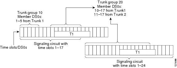
Structure and Relationship of a Dial-Out DS0 Level Trunk Group
Figure 1 shows the structure of a dial-out trunk group. Each trunk group can consist of DS0s from various signaling circuits, but with the restriction that a single DS0 can belong to only one trunk group.
Figure 1 Dial-Out DS0 Level Trunk Group Structure
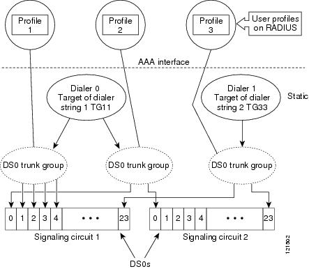
Each dial-out trunk group is typically associated with one or more dial-out user profiles. Figure 2 shows various DS0s aggregated into trunk groups, which are referenced by dial-out profiles that reside on a AAA server.
Figure 2 Relationship of Dial-Out DS0 Level Trunk Groups to RADIUS Profiles
The dial-out trunk group configuration must be explicitly defined on the NAS and cannot be set up using other external components such as AAA, because they represent static functional configurations or configurable system resources on the NAS.
How to Configure Dial-Out DS0 Level Trunk Groups and Enable for DDR
This section contains tasks for configuring dial-out trunk groups and enabling them on DDR. Your network configuration will determine which of the following tasks you require:
•
•
•
•
Configuring Dial-Out DS0 Level Trunk Groups on a DS1 Configured for CAS Signaling
You can configure single or multiple dial-out trunk groups on CAS. The following task shows how to configure a single dial-out trunk group. Repeat steps 4 through 6 to configure additional DS0 groups.
SUMMARY STEPS
1.
2.
3.
4.
5.
6.
7.
DETAILED STEPS
Configuring Dial-Out DS0 Level Trunk Groups on an NFAS Member
When NFAS or SS7 is used, signaling can take place over a circuit different than the one over which the data is being transported. The dial-out trunk group configuration is done in controller configuration mode. If a trunk groups is configured under an NFAS primary serial interface, all NFAS group interface member DS0s are added into the trunk groups. The NFAS primary serial interface will not have the time slot option enabled under its configuration mode.
SUMMARY STEPS
1.
2.
3.
4.
5.
6.
DETAILED STEPS
Configuring Dial-Out DS0 Level Trunk Groups on DS1 Configured for ISDN PRI
The task in this section configures a dial-out trunk group on a PRI.
SUMMARY STEPS
1.
2.
3.
4.
5.
6.
7.
8.
DETAILED STEPS
Associating DS0 Trunk Groups with Dialer
The large-scale dial-out framework that governs dial-out trunk groups enables the provisioning of dial-out configurations on a AAA server. A trunk group label can also be configured as part of a dialer string command, or the large-scale dial-out framework can be used to download the trunk group identifier along with the dialer string. The task in this section shows how to set up a static dial-out configuration for DDR over DS0 trunk groups, and is done by configuring a dialer interface, setting up a profile on the AAA server, and applying a static dial-out trunk configuration on an NAS.
SUMMARY STEPS
1.
2.
3.
4.
5.
6.
7.
8.
9.
10.
11.
12.
DETAILED STEPS
What to Do Next
Use the following dial-out trunk group statements in the profile file that sets up the AAA server to apply a static dial-out DS0 trunk configuration on an NAS.
Note
Configuration Examples for Dial-Out DS0 Level Trunk Groups
This section contains the following configuration examples:
•
•
•
•
•
Configure a Dial-Out DS0 Level Trunk Group on a DS1 Configured for CAS: Example
The following example shows how to configure a single DS0 group on a CAS:
controller t1 0
ds0-group 2 timeslots 1-24
cas-custom 2
trunk-group label3 timeslots 1-12
trunk-group label4 timeslots 13-24 preference 2
controller t1 2
ds0-group 4 timeslots 1-24
cas-custom 4
trunk-group label5 timeslots 1-24 preference
Configure Multiple Dial-Out DS0 Level Trunk Groups on a PRI Trunk: Example
The following example shows how to configure B channels from a PRI channel into a DS0 trunk group:
controller T1 0
pri-group timeslots 1-24
trunk-group L1 timeslots 1-5 preference 10
!
The following example shows how to include all the B channels of the PRI channel into a trunk group:
interface serial 0:23
trunk-group L2 20
Note
Configure Dial-Out DS0 Level Trunk Groups on an NFAS Group: Example
The following example shows how to configure NFAS/SS7 circuits. With these circuits, signaling can take place over a circuit different than the one over which the data is being transported. The DS0 dial-out trunk group configuration is done in controller configuration mode. Because the trunk group is configured under the NFAS primary serial interface, all the NFAS group interface member DS0s are added into the trunk group. The NFAS primary serial interface will not have the timeslots keyword enabled under its configuration mode. The timeslots option is not available in the serial interface configuration mode, because a serial interface may represent an NFAS serial interface.
controller T1 0pri-group timeslots 1-24 nfas_d primary nfas_int 0 nfas_group 0trunk-group L1 timeslots 1-5 preference 1trunk-group L2 timeslots 12-14 preference 2!controller T1 1pri-group timeslots 1-24 nfas_d backup nfas_int 1 nfas_group 0trunk-group L3 timeslots 1-5trunk-group L4 timeslots 12-14 preference 4!controller T1 3pri-group timeslots 1-24 nfas_d none nfas_int 2 nfas_group 0trunk-group L5 timeslots 7,9,11trunk-group L6 timeslots 2,4,6,14-16 preference 6The following example shows how to include all the B channels of the PRI channel into a trunk group:
interface serial 0:23trunk-group trunk5 20
Note
Configure Dial-Out DS0 Level Trunk Groups in a Dialer Rotary Group: Examples
In the following examples, dial-out trunk groups 15 and 16 have DS0s from PRI interfaces 0:23 and 6:23. These interfaces are also rotary members of dialer interface 0. The AAA profile named dialout-out refers to trunk group 16, implying that a DS0 from trunk group 16 will be assigned for the outgoing call for this user using the dialout-out profile.
AAA Server Configuration
dialout-out Password="cisco"Cisco-AVPair = "outbound:trunkgroup=16"Service-Type = Outbound,Cisco-AVPair = "outbound:addr*10.121.94.254",Cisco-AVPair = "Outbound:dial-number=5550101",RAS-5400-1 Password="cisco"Service-Type = Outbound,Framed-Route="10.121.94.254/32 Dialer0 200 name dialout"Framed-Route="10.121.94.0/24 10.121.94.254 200"Dial-Out DS0 Level Trunk Group Configuration on the NAS
controller T1 0pri-group timeslots 1-24trunk-group 16 timeslots 1,21-22 preference 1trunk-group 15 timeslots 18-19...interface serial 0:23dialer rotary-group 0controller T1 6pri-group timeslots 1-24trunk-group 16 timeslots 21-22trunk-group 15 timeslots 18-19 preference 2...interface serial 6:23dialer rotary-group 0interface dialer 0dialer aaaIn the following examples, trunk group 15 has member DS0s from PRI interfaces 0:23, 6:23, and 7:23. PRI interfaces 6:23, and 7:23 are assigned to the same rotary group. When an outgoing call is placed through interface dialer 0, TGRM could return a DS0 that belongs to PRI interfaces 6:23, 7:23, or 0:23. But because PRI interfaces 0:23 are not rotary members of interface dialer 0, the call would fail.
Incorrect AAA Server Configuration
dialout-out Password="cisco"Cisco-AVPair = "outbound:trunkgroup=16"Service-Type = Outbound,Cisco-AVPair = "outbound:addr*10.121.94.254",Cisco-AVPair = "Outbound:dial-number=5550101",RAS-5400-1 Password="cisco"Service-Type = Outbound,Framed-Route="10.121.94.254/32 Dialer0 200 name dialout"Framed-Route="10.121.94.0/24 10.121.94.254 200"...Incorrect Static Dial-Out DS0 Level Trunk Group Configuration on the NAS
controller t1 0pri-group timeslots 1-24trunk-group 15 timeslots 1,21-22 preference 1trunk-group 16 timeslots 18-19interface serial 0:23dialer rotary-group 0controller t1 6pri-group timeslots 1-24trunk-group 15 timeslots 21-22trunk-group 16 timeslots 18-19 preference 2interface serial 6:23dialer rotary-group 1controller t1 7pri-group timeslots 1-24trunk-group 15 timeslots 18-19interface serial 7:23dialer rotary-group 1interface dialer 0dialer aaaAssociating a DS0 Trunk Group with a Dialer for DDR: Example
The following example shows the configurations needed to apply a static dial-out trunk group:
Dialer Interface Configuration:
interface dialer 0dialer string 5550101 trunkgroup 16Static Dial-Out Trunk Group Configuration on the NAS
controller T1 6/1framing esflinecode b8zspri-group timeslots 1-24trunk-group 16 timeslots 1,21-22 preference 1trunk-group 15 timeslots 18-19Additional References
The following sections provide references related to dial-out trunk groups.
Related Documents
Large-scale dial-out
"Configuring Large-Scale Dial-Out" chapter in the Cisco IOS Dial Technologies Configuration Guide, Release 12.3
ISDN signaling circuits
"Signaling Configuration" part in the Cisco IOS Dial Technologies Configuration Guide, Release 12.3
ISDN signaling circuit and large-scale dial-out commands, including syntax and examples
Cisco IOS Dial Technologies Command Reference, Release 12.3
Standards
MIBs
None
To locate and download MIBs for selected platforms, Cisco IOS releases, and feature sets, use Cisco MIB Locator found at the following URL:
RFCs
Technical Assistance
Command Reference
The following commands are introduced or modified in the feature or features documented in this module. For information about these commands, see the Cisco IOS Dial Technologies Command Reference at http://www.cisco.com/en/US/docs/ios/dial/command/reference/dia_book.html. For information about all Cisco IOS commands, go to the Command Lookup Tool at http://tools.cisco.com/Support/CLILookup or to the Cisco IOS Master Commands List.
New Commands
•
•
Modified Command
•
Cisco and the Cisco Logo are trademarks of Cisco Systems, Inc. and/or its affiliates in the U.S. and other countries. A listing of Cisco's trademarks can be found at www.cisco.com/go/trademarks. Third party trademarks mentioned are the property of their respective owners. The use of the word partner does not imply a partnership relationship between Cisco and any other company. (1005R)
Any Internet Protocol (IP) addresses and phone numbers used in this document are not intended to be actual addresses and phone numbers. Any examples, command display output, network topology diagrams, and other figures included in the document are shown for illustrative purposes only. Any use of actual IP addresses or phone numbers in illustrative content is unintentional and coincidental.
© 2007-2009 Cisco Systems, Inc. All rights reserved.