-
Dial Configuration Guide, Cisco IOS Release 15M&T
- Part 1: Dial Interfaces, Controllers, and Lines
-
Part 2: Modem Configuration and Management
-
Overview of Modem Interfaces
-
Configuring and Managing Integrated Modems
-
1- and 2-Port V.90 Modem WICs for Cisco 2600 and Cisco 3600 Series Multiservice Platforms
-
Call Tracker show Commands Extensions
-
Cisco NM-8AM-V2 and NM-16AM-V2 Analog Modem Network Modules with V.92
-
MICA and NextPort Modem Tech-Support Command Additions
-
PIAFS Wireless Data Protocol Version 2.1 for Cisco MICA Modems
-
V.92 and V.44 Support for Digital Modems
-
V.92 Modem on Hold for Cisco AS5300 and Cisco AS5800 Universal Access Servers
-
V.92 Modem on Hold for Cisco AS5350, Cisco AS5400, and Cisco AS5850 Universal Gateways and Cisco AS5800 Universal Access Servers
-
V.92 Quick Connect for Cisco AS5300 and Cisco AS5800 Universal Access Servers
-
V.92 Quick Connect for Cisco AS5350, Cisco AS5400, and Cisco AS5850 Universal Gateways and Cisco AS5800 Universal Access Servers
-
V.92 Reporting Using RADIUS Attribute v.92-info
-
Configuring and Managing Cisco Access Servers and Dial Shelves
-
Configuring and Managing External Modems
-
Modem Signal and Line States
-
Creating and Using Modem Chat Scripts
-
Cisco Modem User Interface
-
Modem Script and System Script Support in Large-Scale Dial-Out
-
-
Part 3: ISDN Configuration
-
Configuring ISDN BRI
-
Leased and Switched BRI Interface for ETSI NET3
-
ISDN BCAC and Round-Robin Channel Selection Enhancements
-
Configuring Virtual Asynchronous Traffic over ISDN
-
Configuring Modem Use over ISDN BRI
-
Configuring X.25 on ISDN
-
Configuring X.25 on ISDN Using AO/DI
-
Configuring ISDN on Cisco 800 Series Routers
-
- Part 4: Signaling Configuration
-
Part 5: Dial-on-Demand Routing Configuration
-
Preparing to Configure DDR
-
Configuring Legacy DDR Spokes
-
Configuring Legacy DDR Hubs
-
Configuring Peer-to-Peer DDR with Dialer Profiles
-
Dialer Map VRF-Aware for an MPLS VPN
-
Dialer Persistent
-
PPPoE Client DDR Idle-Timer
-
Redial Enhancements
-
Rotating Through Dial Strings
-
Configuring Dialer CEF
-
CEF Support for Dialer Profiles on Cisco 7500 Routers
-
IPv6 Cisco Express Forwarding Switching on Dialer Interfaces
-
Configuring Snapshot Routing
-
- Part 6: Dial-Backup Configuration
- Part 7: Dial-Related Addressing Services
- Part 8: Virtual Templates and Profiles
-
Part 9: PPP Configuration
-
Configuring Asynchronous SLIP and PPP
-
Optimized PPP Negotiation
-
Customer Profile Idle Timer Enhancements for Interesting Traffic
-
Multilink PPP Minimum Links Mandatory
-
Configuring Media-Independent PPP and Multilink PPP
-
PPP/MLP MRRU Negotiation Configuration
-
Troubleshooting Enhancements for Multilink PPP over ATM Link Fragmentation and Interleaving
-
Multichassis Multilink PPP
-
- Part 10: Callback and Bandwidth Allocation Configuration
- Configuring Large-Scale Dial-Out
- Part 11: Dial Access Specialized Features
- Part 12: Dial Access Scenarios
 Feedback
Table Of Contents
Enterprise Dial Scenarios and Configurations
Remote Offices and Telecommuters Dialing In to a Central Site
Cisco 1604 Remote Office Router Dialing In to a Cisco 3620 Access Router
Remote Office Router Dialing In to a Cisco 3620 Router
Cisco 700 Series Router Using Port Address Translation to Dial In to a Cisco AS5300 Access Server
Cisco 3640 Central Site Router Configuration to Support ISDN and Modem Calls
Cisco AS5300 Central Site Configuration Using Remote Security
Bidirectional Dial Between Central Sites and Remote Offices
Dial-In and Dial-Out Network Topology
Dialer Profiles and Virtual Profiles
Running Access Server Configurations
Cisco AS5300 Access Server Configuration with Dialer Profiles
Cisco 1604 ISDN Router Configuration with Dialer Profiles
Cisco 1604 Router Asynchronous Configuration with Dialer Profiles
Cisco AS5300 Access Server Configuration Without Dialer Profiles
Cisco 1604 ISDN Router Configuration Without Dialer Profiles
Cisco 1604 Router Asynchronous Configuration Without Dialer Profiles
Large-Scale Dial-In Configuration Using Virtual Profiles
Telecommuters Dialing In to a Mixed Protocol Environment
Mixed Protocol Dial-In Scenarios
Cisco AS5300 Universal Access Server
Enterprise Dial Scenarios and Configurations
This chapter provides sample configurations for specific dial scenarios used by enterprise networks (not telephone companies or Internet service providers). Each configuration is designed to support IP network traffic with basic security for the specified scenario.
The following scenarios are described:
•
Scenario 1—Remote Offices and Telecommuters Dialing In to a Central Site
•
•
Note
Remote User Demographics
Employees stationed in remote offices or disparate locations often dial in to central sites or headquarter offices to download or upload files and check e-mail. These employees often dial in to the corporate network from a remote office LAN using ISDN or from another location such as a hotel room using a modem.
The following remote enterprise users typically dial in to enterprise networks:
•
•
•
Demand and Scalability
You need to evaluate scalability and design issues before you build a dial enterprise network. As the number of company employees increases, the number of remote users who need to dial in increases. A good dial solution scales upward as the demand for dial-in ports grows. For example, it is not uncommon for a fast-growing enterprise to grow from a demand of 100 modems to 250 modems in less than one year.
You should always maintain a surplus of dial-in ports to accommodate company growth and occasional increases in access demand. In the early stages of a fast-growing company that has 100 modems installed for 6000 registered remote users, only 50 to 60 modems might be active at the same time. As demand grows over one year, 250 modems might be installed to support 10,000 registered token card holders.
During special company occasions, such as worldwide conventions, demand for remote access can also increase significantly. During such activities, dial-in lines are used heavily throughout the day and evening by remote sales people using laptops to access E-mail and share files. This behavior is indicative of sales people working away from their home territories or sales offices. Network administrators need to prepare for these remote access bursts, which cause significant increases for remote access demand.
Remote Offices and Telecommuters Dialing In to a Central Site
Remote office LANs typically dial in to other networks using ISDN. Remote offices that use Frame Relay require a more costly dedicated link.
Connections initiated by remote offices and telecommuters are brought up on an as-needed basis, which results in substantial cost savings for the company. In dial-on-demand scenarios, users are not connected for long periods of time. The number of remote nodes requiring access is relatively low, and the completion time for the dial-in task is short.
Central sites typically do not dial out to the remote LANs. Instead, central sites respond to calls. Remote sites initiate calls. For example, a field sales office might use ISDN to dial in to and browse a central site's intranet. Additionally a warehouse comprising five employees can use ISDN to log in to a remote network server to download or upload product order information. For an example of bidirectional dialing, see the section "Bidirectional Dial Between Central Sites and Remote Offices" later in this chapter.
Note
Network Topologies
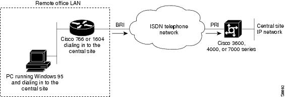
Figure 1 shows an example of a remote office that places digital calls in to a central site network. The remote office router can be any Cisco router with a BRI physical interface, such as a Cisco 766 or Cisco 1604 router. The central office gateway router can be any Cisco router that supports PRI connections, such as a Cisco 3600 series, Cisco 4000 series, or Cisco 7000 series router.
Figure 1 Remote Office Dialing In to a Central Site
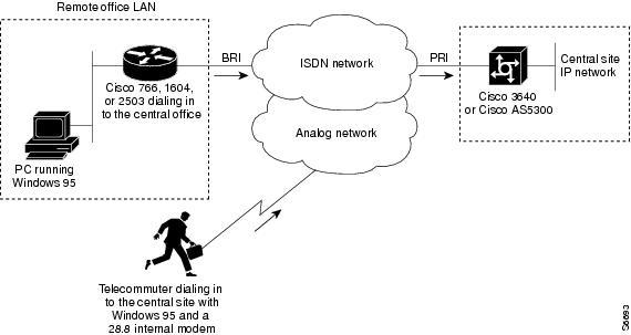
Figure 2 shows an example of a remote office and telecommuter dialing in to a central site. The remote office places digital calls. The telecommuter places analog calls. The remote office router can be any Cisco router with a BRI interface, such as a Cisco 766, Cisco 1604, or Cisco 2503 router. The central office gateway router is a Cisco AS5300 series access server or a Cisco 3640 router, which supports both PRI and analog connections.
Figure 2 Remote Office and Telecommuter Dialing In to a Central Site
Dial-In Scenarios
The configuration examples in the following sections provide different combinations of dial-in scenarios, which can be derived from Figure 1 and Figure 2:
•
•
•
•
•
Note
Cisco 1604 Remote Office Router Dialing In to a Cisco 3620 Access Router
This section provides a common configuration for a Cisco 1604 remote office router dialing in to a Cisco 3620 access router positioned at a central enterprise site. Only ISDN digital calls are supported in this scenario. No analog modem calls are supported. All calls are initiated by the remote router on an as-needed basis. The Cisco 3620 router is not set up to dial out to the Cisco 1604 router. (Refer to Figure 1.)
The Cisco 1604 and Cisco 3620 routers use the IP unnumbered address configurations, MLP, and the dial-load threshold feature, which brings up the second B channel when the first B channel exceeds a certain limit. Because static routes are used, a routing protocol is not configured. A default static route is configured on the Cisco 1604 router, which points back to the central site. The central site also has a static route that points back to the remote LAN. Static route configurations assume that you have only one LAN segment at each remote office.
Cisco 1604 Router Configuration
The following configuration runs on the Cisco 1604 router, shown in Figure 1. This SOHO router places digital calls in to the Cisco 3620 central site access router. See the next example for the running configuration of the Cisco 3620 router.
version xx.xservice timestamps debug datetime msecservice timestamps log datetime msecservice password-encryptionno service udp-small-serversno service tcp-small-servers!hostname remotelan1!enable secret cisco!username NAS password dialpassusername admin password ciscoisdn switch-type basic-5ess!interface Ethernet0ip address 10.2.1.1 255.255.255.0!interface BRI0ip unnumbered Ethernet0encapsulation pppdialer map ip 10.1.1.10 name NAS 5551234dialer load-threshold 100 eitherdialer-group 1no fair-queueppp authentication chap pap callinppp multilink!ip classlessip route 0.0.0.0 0.0.0.0 10.1.1.10ip route 10.1.1.10 255.255.255.255 BRI0dialer-list 1 protocol ip permit!line con 0line vty 0 4login local!endCisco 3620 Router Configuration
The following sample configuration runs on the Cisco 3620 router shown in Figure 1. This modular access router has one 2-port PRI network module installed in slot 1 and one 1-port Ethernet network module installed in slot 0. The router receives only digital ISDN calls from the Cisco 1604 router. The configuration for the Cisco 1604 router was provided in the previous example.
version xx.xservice timestamps debug datetime msecservice timestamps log datetime msecservice password-encryptionno service udp-small-serversno service tcp-small-servers!hostname NAS!aaa new-modelaaa authentication login default localaaa authentication login console enableaaa authentication login vty localaaa authentication login dialin localaaa authentication ppp default localaaa authentication ppp dialin if-needed localenable secret cisco!username admin password ciscousername remotelan1 password dialpassasync-bootp dns-server 10.1.3.1 10.1.3.2isdn switch-type primary-5ess!controller T1 1/0framing esfclock source linelinecode b8zspri-group timeslots 1-24!controller T1 1/1framing esfclock source linelinecode b8zspri-group timeslots 1-24!interface Loopback0ip address 10.1.2.254 255.255.255.0!interface Ethernet 0/0ip address 10.1.1.10 255.255.255.0ip summary address eigrp 10 10.1.2.0 255.255.255.0!interface Serial 1/0:23no ip addressencapsulation pppisdn incoming-voice modemdialer rotary-group 0dialer-group 1no fair-queueno cdp enable!interface Serial 1/1:23no ip addressencapsulation pppisdn incoming-voice modemdialer rotary-group 0dialer-group 1no fair-queueno cdp enable!interface Dialer0ip unnumbered Loopback0no ip mroute-cacheencapsulation ppppeer default ip address pool dialin_pooldialer in-banddialer-group 1no fair-queueno cdp enableppp authentication chap pap dialinppp multilink!router eigrp 10network 10.0.0.0passive-interface Dialer0default-metric 64 100 250 100 1500redistribute staticno auto-summary!ip local pool dialin_pool 10.1.2.1 10.1.2.50ip default-gateway 10.1.1.1ip route 10.2.1.1 255.255.255.255 Dialer0ip route 10.2.1.0 255.255.255.0 10.2.1.1ip classless!dialer-list 1 protocol ip permit!line con 0login authentication consoleline aux 0login authentication consoleline vty 0 4login authentication vtytransport input telnet rlogin!endRemote Office Router Dialing In to a Cisco 3620 Router
This section provides a common configuration for a Cisco 700 or 800 series remote office router placing digital calls in to a Cisco 3620 router positioned at a central enterprise site. All calls are initiated by the remote router on an as-needed basis. The Cisco 3620 router is not set up to dial out to the remote office router. (See Figure 1.)
Cisco 700 Series Router Configuration
The following configuration task is for a Cisco 700 series ISDN router placing digital calls in to a central site router that supports ISDN PRI, such as the Cisco 3620 router. In this scenario, ISDN unnumbered interfaces with static routes are pointing back to the Cisco 3620.
To configure the router, use the following commands in EXEC mode. However, this configuration assumes that you are starting from the router's default configuration. To return the router to its default configuration, issue the set default command.
After you configure the Cisco 760 or Cisco 770 series router, the final configuration should resemble the following:
set systemname remotelan1set ppp secret clientset encapsulation pppset ppp multilink oncd lanset bridging offset ip routing onset ip 10.2.1.1set subnet 255.255.255.0set user nasset bridging offset ip 0.0.0.0set ip netmask 0.0.0.0set ip framing noneset ip route destination 0.0.0.0 gateway 10.1.1.10set timeout 300set 1 number 5551234set 2 number 5551234The previous software configuration does not provide for any access security. To provide access security, use the following optional commands in EXEC mode:
Cisco 3620 Router Configuration
The following example provides a sample configuration for the Cisco 3620 router. This modular access router has one 2-port PRI network module installed in slot 1 and one 1-port Ethernet network module installed in slot 0. The router receives only digital ISDN calls over T1 lines from the Cisco 700 series remote office router, which was described in the previous example.
version xx.xservice timestamps debug datetime msecservice timestamps log datetime msecservice password-encryptionno service udp-small-serversno service tcp-small-servershostname NAS!aaa new-modelaaa authentication login default localaaa authentication login console enableaaa authentication login vty localaaa authentication login dialin localaaa authentication ppp default localaaa authentication ppp dialin if-needed localenable secret cisco!username admin password ciscousername remotelan1 password dialpass!async-bootp dns-server 10.1.3.1 10.1.3.2isdn switch-type primary-5ess!controller T1 1/0framing esfclock source linelinecode b8zspri-group timeslots 1-24!controller T1 1/1framing esfclock source linelinecode b8zspri-group timeslots 1-24!interface Loopback0ip address 10.1.2.254 255.255.255.0!interface Ethernet 0/0ip address 10.1.1.10 255.255.255.0ip summary address eigrp 10 10.1.2.0 255.255.255.0!interface Serial 1/0:23no ip addressencapsulation pppisdn incoming-voice modemdialer rotary-group 0dialer-group 1no fair-queueno cdp enable!interface Serial 1/1:23no ip addressencapsulation pppisdn incoming-voice modemdialer rotary-group 0dialer-group 1no fair-queueno cdp enable!interface Dialer0ip unnumbered Loopback0no ip mroute-cacheencapsulation ppppeer default ip address pool dialin_pooldialer in-banddialer-group 1no fair-queueno cdp enableppp authentication chap pap dialinppp multilink!router eigrp 10network 10.0.0.0passive-interface Dialer0default-metric 64 100 250 100 1500redistribute staticno auto-summary!ip local pool dialin_pool 10.1.2.1 10.1.2.50ip default-gateway 10.1.1.1ip route 10.2.1.1 255.255.255.255 Dialer0ip route 10.2.1.0 255.255.255.0 10.2.1.1ip classless!dialer-list 1 protocol ip permit!line con 0login authentication consoleline aux 0login authentication consoleline vty 0 4login authentication vtytransport input telnet rlogin!endCisco 700 Series Router Using Port Address Translation to Dial In to a Cisco AS5300 Access Server
This section shows a Cisco 700 series router using the port address translation (PAT) feature to dial in to a Cisco AS5300 central site access server. IP addresses are assigned from the central site, which leverages the PAT feature to streamline multiple devices at the remote site through a single assigned address. In this example, the Cisco 700 series router has a private range of IP addresses used on the Ethernet side. However, the router is able to translate between the local private addresses and the dynamically registered address on the WAN interface. (See Figure 1.)
Cisco 700 Series Configuration
The sample configuration in this section allows PCs on a LAN to boot up and acquire their IP address dynamically from a Cisco 700 series router, which in turn translates the private addresses into a single IP address assigned from a Cisco AS5300 central site router. The Cisco 700 series router also passes information via DHCP regarding the Domain Name System (DNS) server (in this example, 10.2.10.1) and the Windows Internet naming service (WINS) server (in this example, 10.2.11.1) along with the domain name.
A possible sequence of events would be a remote PC running Windows 95 boots up on the Ethernet segment and gets its IP address and network information from the Cisco 700 series router. The PC then opens up Netscape and attempts to view a web page at the central site, which causes the router to dial in to the central site. The router dynamically obtains its address from the central site pool of addresses and uses it to translate between the private address on the local Ethernet segment and the registered IP address borrowed from the central site router.
To configure a remote router, use the following commands beginning in EXEC mode:
After you configure the router, the configuration should resemble the following:
set systemname remotelan1set encapsulation pppset ppp secret clientset ppp multilink onset dhcp serverset dhcp dns primary 10.2.10.1set dhcp wins 10.2.11.1set dhcp domain nas.comset user nasset bridging offset ip routing onset ip framing noneset ip pat onset ip route destination 0.0.0.0 gateway 10.1.1.0set 1 number 5551234set 2 number 5551234Cisco AS5300 Router Configuration
The following example configures a Cisco AS5300 router for receiving calls from the router in the previous example.
Note
!version xx.xservice timestamps debug datetime msecservice timestamps log datetime msecservice password-encryptionno service udp-small-serversno service tcp-small-servers!hostname NAS!aaa new-modelaaa authentication login default localaaa authentication login console enableaaa authentication login vty localaaa authentication login dialin localaaa authentication ppp default localaaa authentication ppp dialin if-needed localenable secret cisco!username admin password ciscousername remotelan1 password dialpass!async-bootp dns-server 10.1.3.1 10.1.3.2isdn switch-type primary-5ess!controller T1 0framing esfclock source line primarylinecode b8zspri-group timeslots 1-24!controller T1 1framing esfclock source line secondarylinecode b8zspri-group timeslots 1-24!interface Loopback0ip address 10.1.2.254 255.255.255.0!interface Ethernet0ip address 10.1.1.10 255.255.255.0ip summary address eigrp 10 10.1.2.0 255.255.255.0!interface Serial0no ip addressshutdown!interface Serial1no ip addressshutdown!interface Serial0:23no ip addressencapsulation pppisdn incoming-voice modemdialer rotary-group 0dialer-group 1no fair-queueno cdp enable!interface Serial1:23no ip addressencapsulation pppisdn incoming-voice modemdialer rotary-group 0dialer-group 1no fair-queueno cdp enable!interface Dialer0ip unnumbered Loopback0no ip mroute-cacheencapsulation ppppeer default ip address pool dialin_pooldialer in-banddialer-group 1no fair-queueno cdp enableppp authentication chap pap dialinppp multilink!router eigrp 10network 10.0.0.0passive-interface Dialer0default-metric 64 100 250 100 1500redistribute staticno auto-summary!ip local pool dialin_pool 10.1.2.1 10.1.2.50ip default-gateway 10.1.1.1ip route 10.2.1.1 255.255.255.255 Dialer0ip route 10.2.1.0 255.255.255.0 10.2.1.1ip classless!dialer-list 1 protocol ip permit!line con 0login authentication consoleline aux 0login authentication consoleline vty 0 4login authentication vtytransport input telnet rlogin!endIn this configuration, the local pool is using a range of unused addresses on the same subnet on which the Ethernet interface is configured. The addresses will be used for the remote devices dialing in to the Cisco AS5300 access server.
Cisco 3640 Central Site Router Configuration to Support ISDN and Modem Calls
The following configuration allows remote LANs and standalone remote users with modems to dial in to a central site. Figure 2 shows the network topology.
The Cisco 3640 router has the following hardware configuration for this scenario:
•
•
•
Note
version xx.xservice timestamps debug datetime msecservice timestamps log datetime msecservice password-encryptionno service udp-small-serversno service tcp-small-servers!hostname NAS!aaa new-modelaaa authentication login default localaaa authentication login console enableaaa authentication login vty localaaa authentication login dialin localaaa authentication ppp default localaaa authentication ppp dialin if-needed localenable secret cisco!username admin password ciscousername remotelan1 password dialpass1username remotelan2 password dialpass2username PCuser1 password dialpass3username PCuser2 password dialpass4!async-bootp dns-server 10.1.3.1 10.1.3.2isdn switch-type primary-5ess!controller T1 1/0framing esfclock source linelinecode b8zspri-group timeslots 1-24!controller T1 1/1framing esfclock source linelinecode b8zspri-group timeslots 1-24!interface Loopback0ip address 10.1.2.254 255.255.255.0!interface Ethernet0/0ip address 10.1.1.10 255.255.255.0ip summary address eigrp 10 10.1.2.0 255.255.255.0!interface Serial 1/0:23no ip addressencapsulation pppisdn incoming-voice modemdialer rotary-group 0dialer-group 1no fair-queueno cdp enable!interface Serial 1/1:23no ip addressencapsulation pppisdn incoming-voice modemdialer rotary-group 0dialer-group 1no fair-queueno cdp enable!interface Group-Async1ip unnumbered Loopback0encapsulation pppasync mode interactivepeer default ip address pool dialin_poolno cdp enableppp authentication chap pap dialingroup-range 65 88!interface Group-Async2ip unnumbered Loopback0encapsulation pppasync mode interactivepeer default ip address pool dialin_poolno cdp enableppp authentication chap pap dialingroup-range 97 120!interface Dialer0ip unnumbered Loopback0no ip mroute-cacheencapsulation ppppeer default ip address pool dialin_pooldialer in-banddialer-group 1no fair-queueno cdp enableppp authentication chap pap dialinppp multilink!router eigrp 10network 10.0.0.0passive-interface Dialer0no auto-summary!ip local pool dialin_pool 10.1.2.1 10.1.2.50ip default-gateway 10.1.1.1ip classless!dialer-list 1 protocol ip permit!line con 0login authentication consoleline 65 88autoselect pppautoselect during-loginlogin authentication dialinmodem DialInline 97 120autoselect pppautoselect during-loginlogin authentication dialinmodem DialInline aux 0login authentication consoleline vty 0 4login authentication vtytransport input telnet rlogin!endCisco AS5300 Central Site Configuration Using Remote Security
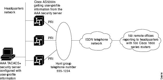
The previous examples in this section configured static CHAP authentication on the central router using the username command. A more common configuration to support modem and ISDN calls on a single chassis is to use the AAA security model and an external security server at the central site. We recommend that you have a solid understanding of basic security principles and the AAA model before you set up this configuration. For more information about security, see the Cisco IOS Security Configuration Guide.
Central Site Cisco AS5300 Configuration Using TACACS+ Authentication
The following example assumes that you are running TACACS+ on the remote security server:
version xx.xservice timestamps debug datetime msecservice timestamps log datetime msecservice password-encryptionno service udp-small-serversno service tcp-small-servers!hostname NAS!aaa new-modelaaa authentication login console enableaaa authentication login vty tacacs+aaa authentication login dialin tacacs+aaa authentication ppp default tacacs+aaa authentication ppp dialin if-needed tacacs+enable secret cisco!async-bootp dns-server 10.1.3.1 10.1.3.2isdn switch-type primary-5ess!controller T1 0framing esfclock source line primarylinecode b8zspri-group timeslots 1-24!controller T1 1framing esfclock source line secondarylinecode b8zspri-group timeslots 1-24!interface Loopback0ip address 10.1.2.254 255.255.255.0!interface Ethernet0ip address 10.1.1.10 255.255.255.0ip summary address eigrp 10 10.1.2.0 255.255.255.0!interface Serial0no ip addressshutdown!interface Serial1no ip addressshutdown!interface Serial0:23no ip addressencapsulation pppisdn incoming-voice modemdialer rotary-group 0dialer-group 1no fair-queueno cdp enable!interface Serial1:23no ip addressencapsulation pppisdn incoming-voice modemdialer rotary-group 0dialer-group 1no fair-queueno cdp enable!interface Group-Async1ip unnumbered Loopback0encapsulation pppasync mode interactivepeer default ip address pool dialin_poolno cdp enableppp authentication chap pap dialingroup-range 1 48!interface Dialer0ip unnumbered Loopback0no ip mroute-cacheencapsulation ppppeer default ip address pool dialin_pooldialer in-banddialer-group 1no fair-queueno cdp enableppp authentication chap pap dialinppp multilink!router eigrp 10network 10.0.0.0passive-interface Dialer0redistribute staticdefault-metric 64 100 250 100 1500no auto-summary!ip local pool dialin_pool 10.1.2.1 10.1.2.50ip default-gateway 10.1.1.1ip classless!dialer-list 1 protocol ip permit!line con 0login authentication consoleline 1 48autoselect pppautoselect during-loginlogin authentication dialinmodem DialInline aux 0login authentication consoleline vty 0 4login authentication vtytransport input telnet rloginendTACACS+ Security Server Entry
The following example can be configured on a remote TACACS+ security server, which complements the Cisco AS5300 access server configuration listed in the previous example:
user = remotelan1 {chap = cleartext "dialpass1"service = ppp protocol = ip {addr = 10.2.1.1route = "10.2.1.0 255.255.255.0"}}user = PCuser1 {login = cleartext "dialpass2"chap = cleartext "dialpass2"service = ppp protocol = ip {addr-pool = dialin_pool}service = exec {autocmd = "ppp negotiate"}}user = PCuser2 {login = cleartext "dialpass3"chap = cleartext "dialpass3"service = ppp protocol = ip {addr-pool = dialin_pool}service = exec {autocmd = "ppp negotiate"}Bidirectional Dial Between Central Sites and Remote Offices
Sometimes a gateway access server at headquarters is required to dial out to a remote site while simultaneously receiving incoming calls. This type of network is designed around a specific business support model.
Dial-In and Dial-Out Network Topology
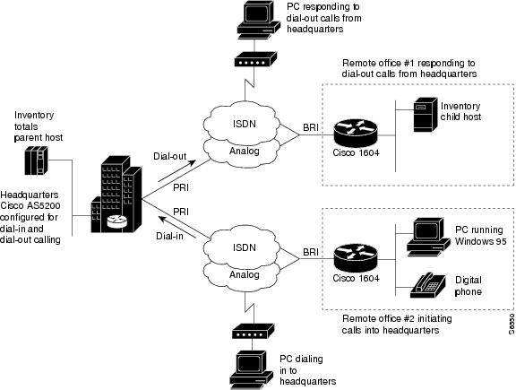
Figure 3 shows a typical dial-in and dial-out network scenario, which amounts to only 25 percent of all dial topologies. The Cisco AS5300 access server at headquarters initiates a connection with a Cisco 1604 router at remote office 1. After a connection is established, the file server at the remote site (shown as Inventory child host) runs a batch processing application with the mainframe at headquarters (shown as Inventory totals parent host). While files are being transferred between remote office 1 and headquarters, remote office 2 is successfully dialing in to headquarters.
Figure 3 Headquarters Configured for Dial-In and Dial-out Networking
There are some restrictions for dial-out calling. Dial-out analog and digital calls are commonly made to remote ISDN routers, such as the Cisco 1604 router. On the whole, dial out calls are not made from a central site router to a remote PC but rather from a remote PC in to the central site. However, central site post offices often call remote office routers on demand to deliver E-mail. Callback is enabled on dial-in scenarios only. The majority of a dial out software configuration is setup on the router at headquarters, not the remote office router. Dialing out to a stack group of multiple chassis is not supported by Cisco IOS software. Note that Multichassis Multilink PPP (MMP) and virtual private dialup networks (VPDNs) are dial-in only solutions.
Dialer Profiles and Virtual Profiles
Profiles are set up to discriminate access on a user-specific basis. For example, if the chief network administrator is dialing in to the enterprise, a unique user profile can be created with an idle timeout of one year, and universal access privileges to all networks in the company. For less fortunate users, access can be restricted to an idle timeout of 10 seconds and network connections setup for only a few addresses.
Depending on the size and scope of your dial solution, you can set up two different types of profiles: dialer profiles or virtual profiles. Dialer profiles are individual user profiles set up on routers or access servers in a small-scale dial solution. This type of profile is configured locally on the router and is limited by the number of interfaces that exist on the router. When an incoming call comes into the dial pool, the dialer interface binds the caller to a dialer profile via the caller ID or the caller name.
Figure 4 shows an example of how dialer profiles can be used when:
•
•
•
Note
Figure 4 Dial-In Scenario for Dialer Profiles
Virtual profiles are user-specific profiles for large-scale dial solutions; however, these profiles are not manually configured on each router or access server. A virtual profile is a unique PPP application that can create and configure a virtual access interface dynamically when a dial-in call is received, and tear down the interface dynamically when the call ends.
The configuration information for a virtual access interface in a virtual profile can come from the virtual template interface, or from user-specific configuration information stored on an AAA server, or both. The virtual profile user-specific configuration stored on the AAA server is identified by the authentication name for the call-in user. (That is, if the AAA server authenticates the user as samson, the user-specific configuration is listed under samson in the AAA user file.) The virtual profile user-specific configuration should include only the configuration that is not shared by multiple users. Shared configuration should be placed in the virtual template interface, where it can be cloned on many virtual access interfaces as needed.
AAA configurations are much easier to manage for large numbers of dial-in users. Virtual profiles can span across a group of access servers, but a AAA server is required. Virtual profiles are set up independently of which access server, interface, or port number users connect to. For users that share duplicate configuration information, it is best to enclose the configuration in a virtual template. This requirement eliminates the duplication of commands in each of the user records on the AAA server.
The user-specific AAA configuration used by virtual profiles is interface configuration information and downloaded during link control protocol (LCP) negotiations. Another feature, called per-user configuration, also uses configuration information gained from a AAA server. However, per-user configuration uses network configuration (such as access lists and route filters) downloaded during NCP negotiations.
Figure 5 shows an example of how virtual profiles are used:
•
•
•
•
Note
Figure 5 Dial-In Scenario for Virtual Profiles
Running Access Server Configurations
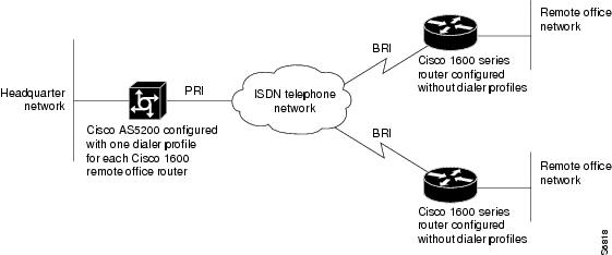
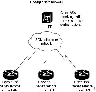
In most cases, dialer profiles are configured on access servers or routers that receive calls and must discriminate between users, such as many different remote routers dialing in. (See Figure 6.)
Figure 6 Remote Cisco 1600s Dialing In to a Cisco AS5300 at the Central Site
Access servers or routers that only place calls (not receive calls) do not need any awareness of configured dialer profiles. Remote routers do not need to discriminate on the basis of which device they are calling in to. For example, if multiple Cisco 1600 series routers are dialing in to one Cisco AS5300 access server, the Cisco 1600 series routers should not be configured with dialer profiles. The Cisco AS5300 access server should be configured with dialer profiles. Do not configure dialer profiles on devices that only make calls.
The configurations examples in the following section are provided for different types of dial scenarios, which can be derived from Figure 3 through Figure 6:
•
–
–
–
•
–
–
–
•
Note
Cisco AS5300 Access Server Configuration with Dialer Profiles
The following bidirectional dial configuration runs on the Cisco AS5300 access server at headquarters in Figure 3. This configuration enables calls to be sent to the SOHO router and received from remote hosts and clients. The calling is bidirectional.
version xx.xservice udp-small-serversservice tcp-small-servers!hostname 5300!aaa new-modelaaa authentication login default localaaa authentication login console enableaaa authentication login vty localaaa authentication login dialin localaaa authentication ppp default localaaa authentication ppp dialin if-needed localenable secret cisco!username async1 password ciscousername async2 password ciscousername async3 password ciscousername async4 password ciscousername async5 password ciscousername async6 password ciscousername async7 password ciscousername async8 password ciscousername isdn1 password ciscousername isdn2 password ciscousername isdn3 password ciscousername isdn4 password ciscousername isdn5 password ciscousername isdn6 password ciscousername isdn7 password ciscousername isdn8 password ciscousername DialupAdmin password cisco!isdn switch-type primary-dms100chat-script cisco-default ABORT ERROR "" "AT" OK "ATDT\T" TIMEOUT 60 CONNECT!controller T1 0framing esfclock source line primarylinecode b8zspri-group timeslots 1-24!controller T1 1framing esfclock source line secondarylinecode b8zspri-group timeslots 1-24!interface loopback 1ip address 172.18.38.40 255.255.255.128!interface loopback 2ip address 172.18.38.130 255.255.255.128!interface Ethernet0ip address 172.18.39.40 255.255.255.0no ip mroute-cacheip ospf priority 0!interface Serial0:23no ip addressno ip mroute-cacheencapsulation pppisdn incoming-voice modemdialer pool-member 2!interface Serial1:23no ip addressno ip mroute-cacheencapsulation pppisdn incoming-voice modemdialer pool-member 2!interface Group-Async1no ip addressno ip mroute-cacheencapsulation pppasync mode interactivedialer in-banddialer pool-member 1ppp authentication chap papgroup-range 1 48!interface Dialer10ip unnumbered loopback 1encapsulation ppppeer default ip address dialin_pooldialer remote-name async1dialer string 14085268983dialer hold-queue 10dialer pool 1dialer-group 1ppp authentication pap chap callinppp pap sent-username DialupAdmin password 7 07063D11542!interface Dialer11ip unnumbered loopback 1encapsulation pppno peer default ip address pooldialer remote-name async2dialer string 14085262012dialer hold-queue 10dialer pool 1dialer-group 1ppp authentication pap chap callinppp pap sent-username DialupAdmin password 7 07063D11542!interface Dialer12ip unnumbered loopback 1encapsulation pppno peer default ip address pooldialer remote-name async3dialer string 14085260706dialer hold-queue 10dialer pool 1dialer-group 1ppp authentication pap chap callinppp pap sent-username DialupAdmin password 7 07063D11542!interface Dialer13ip unnumbered loopback 1encapsulation pppno peer default ip address pooldialer remote-name async4dialer string 14085262731dialer hold-queue 10dialer pool 1dialer-group 1ppp authentication pap chap callinppp pap sent-username DialupAdmin password 7 07063D11542!interface Dialer14ip unnumbered loopback 1encapsulation pppno peer default ip address pooldialer remote-name async5dialer string 14085264431dialer hold-queue 10dialer pool 1dialer-group 1ppp authentication pap chap callinppp pap sent-username DialupAdmin password 7 07063D11542!interface Dialer15ip unnumbered loopback 1encapsulation pppno peer default ip address pooldialer remote-name async6dialer string 14085261933dialer hold-queue 10dialer pool 1dialer-group 1ppp authentication pap chap callinppp pap sent-username DialupAdmin password 7 07063D11542!interface Dialer16ip unnumbered loopback 1encapsulation pppno peer default ip address pooldialer remote-name async7dialer string 14085267631dialer hold-queue 10dialer pool 1dialer-group 1ppp authentication pap chap callinppp pap sent-username DialupAdmin password 7 07063D11542!interface Dialer17ip unnumbered loopback 2encapsulation pppno peer default ip address pooldialer remote-name async8dialer string 14085265153dialer hold-queue 10dialer pool 2dialer-group 1ppp authentication chap pap!interface Dialer18ip unnumbered loopback 2encapsulation pppno peer default ip address pooldialer remote-name isdn1dialer string 14085267887dialer hold-queue 10dialer pool 2dialer-group 1ppp authentication chap pap!interface Dialer19ip unnumbered loopback 2encapsulation pppno peer default ip address pooldialer remote-name isdn2dialer string 14085261591dialer hold-queue 10dialer pool 2dialer-group 1ppp authentication chap pap!interface Dialer20ip unnumbered loopback 2encapsulation pppno peer default ip address pooldialer remote-name isdn3dialer string 14085262118dialer hold-queue 10dialer pool 2dialer-group 1ppp authentication chap pap!interface Dialer21ip unnumbered loopback 2encapsulation pppno peer default ip address pooldialer remote-name isdn4dialer string 14085263757dialer hold-queue 10dialer pool 2dialer-group 1ppp authentication chap pap!interface Dialer22ip unnumbered loopback 2encapsulation pppno peer default ip address pooldialer remote-name isdn5dialer string 14085263769dialer hold-queue 10dialer pool 2dialer-group 1ppp authentication chap pap!interface Dialer23ip unnumbered loopback 2encapsulation pppno peer default ip address pooldialer remote-name isdn6dialer string 14085267884dialer hold-queue 10dialer pool 2dialer-group 1ppp authentication chap pap!interface Dialer24ip unnumbered loopback 2encapsulation pppno peer default ip address pooldialer remote-name isdn7dialer string 14085267360dialer hold-queue 10dialer pool 2dialer-group 1ppp authentication chap pap!interface Dialer25ip unnumbered loopback 2encapsulation pppno peer default ip address pooldialer remote-name isdn8dialer string 14085260361dialer hold-queue 10dialer pool 2dialer-group 1ppp authentication chap pap!router ospf 1redistribute static subnetspassive-interface Dialer1passive-interface Dialer2network 172.18.0.0 0.0.255.255 area 0!ip local pool dialin_pool 10.1.2.1 10.1.2.50ip domain-name cisco.comip classless!dialer-list 1 protocol ip permit!line con 0exec-timeout 0 0line 1 24no execexec-timeout 0 0autoselect during-loginautoselect pppscript dialer cisco-defaultlogin localmodem InOutmodem autoconfigure type microcom_hdmstransport input telnetline aux 0line vty 0 1exec-timeout 60 0password ciscologinline vty 2 5exec-timeout 5 0password ciscologin!endCisco 1604 ISDN Router Configuration with Dialer Profiles
The following configuration runs on the remote office Cisco 1604 router, which receives calls from the Cisco AS5300 central site access server. (See Figure 3.)
version xx.xservice udp-small-serversservice tcp-small-servers!hostname isdn1!enable password cisco!username 5300 password ciscousername isdn1 password ciscoisdn switch-type basic-5ess!interface Ethernet0ip address 172.18.40.1 255.255.255.0!interface BRI0no ip addressencapsulation pppdialer pool-member 1ppp authentication chap pap!interface Dialer1ip address 172.18.38.131 255.255.255.128encapsulation pppno peer default ip address pooldialer remote-name 5300dialer string 14085269328dialer hold-queue 10dialer pool 2dialer-group 1ppp authentication chap pap!ip classlessip route 0.0.0.0 0.0.0.0 172.18.38.130dialer-list 1 protocol ip permit!line con 0line vty 0 4password ciscologinpassword ciscologin!endCisco 1604 Router Asynchronous Configuration with Dialer Profiles
The following asynchronous configuration runs on the remote office Cisco 1604 router, which receives calls from the Cisco AS5300 central site access server. (See Figure 3.)
version xx.xservice udp-small-serversservice tcp-small-servers!hostname async1!enable password cisco!username 5300 password ciscousername async1 password ciscochat script dial_out "" "ATDT\T" timeout 60 connect \c!interface Ethernet0ip address 172.18.41.1 255.255.255.0!interface serial 0physical-layer asyncno ip addressencapsulation pppdialer pool-member 1ppp authentication chap pap!interface Dialer10ip address 172.18.38.41 255.255.255.128encapsulation pppno peer default ip address pooldialer remote-name 5300dialer string 14085269328dialer hold-queue 10dialer pool 1dialer-group 1ppp authentication chap pap!ip classlessip route 0.0.0.0 0.0.0.0 172.18.38.40dialer-list 1 protocol ip permit!line con 0line 1password ciscologinscript modem dial_out!endCisco AS5300 Access Server Configuration Without Dialer Profiles
The following bidirectional dial configuration runs on the Cisco AS5300 access server at headquarters in Figure 3. This configuration enables calls to be sent to the SOHO router and received from remote hosts and clients. The calling is bidirectional.
version xx.xservice udp-small-serversservice tcp-small-servers!hostname 5300!aaa new-modelaaa authentication login default localaaa authentication login console enableaaa authentication login vty localaaa authentication login dialin localaaa authentication ppp default localaaa authentication ppp dialin if-needed localenable secret cisco!username async1 password ciscousername async2 password ciscousername async3 password ciscousername async4 password ciscousername async5 password ciscousername async6 password ciscousername async7 password ciscousername async8 password ciscousername isdn1 password ciscousername isdn2 password ciscousername isdn3 password ciscousername isdn4 password ciscousername isdn5 password ciscousername isdn6 password ciscousername isdn7 password ciscousername isdn8 password ciscousername DialupAdmin password cisco!isdn switch-type primary-dms100chat-script cisco-default ABORT ERROR "" "AT" OK "ATDT\T" TIMEOUT 60 CONNECT!controller T1 0framing esfclock source line primarylinecode b8zspri-group timeslots 1-24description ISDN Controller 0!controller T1 1framing esfclock source line secondarylinecode b8zspri-group timeslots 1-24description ISDN Controller 1!interface Ethernet0ip address 172.18.39.40 255.255.255.0no ip mroute-cacheip ospf priority 0!interface Serial0:23no ip addressno ip mroute-cacheencapsulation pppisdn incoming-voice modemdialer rotary-group 2!interface Serial1:23no ip addressno ip mroute-cacheencapsulation pppisdn incoming-voice modemdialer rotary-group 2!interface Group-Async1no ip addressno ip mroute-cacheencapsulation pppasync dynamic addressasync mode interactivedialer in-banddialer rotary-group 1ppp authentication pap callinppp pap sent-username HQ5300 password 7 09434678520Agroup-range 1 24!interface Dialer1ip address 172.18.38.40 255.255.255.128encapsulation pppno peer default ip address pooldialer in-banddialer map ip 172.18.38.41 name async1 14445558983dialer map ip 172.18.38.42 name async2 14445552012dialer map ip 172.18.38.43 name async3 14445550706dialer map ip 172.18.38.44 name async4 14445552731dialer map ip 172.18.38.45 name async5 14445554431dialer map ip 172.18.38.46 name async6 14445551933dialer map ip 172.18.38.47 name async7 14445557631dialer map ip 172.18.38.48 name async8 14445555153dialer hold-queue 10dialer-group 1ppp authentication pap chap callinppp pap sent-username DialupAdmin password 7 07063D11542!interface Dialer2ip address 172.18.38.130 255.255.255.128encapsulation pppno peer default ip address pooldialer in-banddialer map ip 172.18.38.131 name isdn1 14445557887dialer map ip 172.18.38.132 name isdn2 14445551591dialer map ip 172.18.38.133 name isdn3 14445552118dialer map ip 172.18.38.134 name isdn4 14445553757dialer map ip 172.18.38.135 name isdn5 14445553769dialer map ip 172.18.38.136 name isdn6 14445557884dialer map ip 172.18.38.137 name isdn7 14445557360dialer map ip 172.18.38.138 name isdn8 14445550361dialer hold-queue 10dialer-group 1ppp authentication chap papppp multilink!router ospf 1redistribute static subnetspassive-interface Dialer1passive-interface Dialer2network 172.18.0.0 0.0.255.255 area 0!ip domain-name cisco.comip classless!dialer-list 1 protocol ip permit!line con 0exec-timeout 0 0line 1 24no execexec-timeout 0 0autoselect during-loginautoselect pppscript dialer cisco-defaultlogin localmodem InOutmodem autoconfigure type microcom_hdmstransport input telnetline aux 0line vty 0 1exec-timeout 60 0password ciscologinline vty 2 5exec-timeout 5 0password ciscologin!endCisco 1604 ISDN Router Configuration Without Dialer Profiles
The following configuration runs on the remote office Cisco 1604 router, which dials in to the Cisco AS5300 access server at headquarters in Figure 3. This configuration does not receive calls from the Cisco AS5300 access server.
!version 11.1service udp-small-serversservice tcp-small-servers!hostname isdn1!enable password cisco!username 5300 password ciscousername isdn1 password ciscoisdn switch-type basic-5ess!interface Ethernet0ip address 172.18.40.1 255.255.255.0!interface BRI0ip address 172.18.38.131 255.255.255.128encapsulation pppdialer map ip 172.18.38.130 name 5300 14085269328dialer-group 1ppp authentication chap pap!ip classlessip route 0.0.0.0 0.0.0.0 172.18.38.130dialer-list 1 protocol ip permit!line con 0line vty 0 4password ciscologinpassword ciscologin!endCisco 1604 Router Asynchronous Configuration Without Dialer Profiles
The following asynchronous configuration runs on the remote office Cisco 1604 router, which dials in to the Cisco AS5300 access server at headquarters in Figure 3. This configuration does not receive calls from the Cisco AS5300 access server.
version xx.xservice udp-small-serversservice tcp-small-servers!hostname async1!enable password cisco!username 5300 password ciscousername async1 password ciscochat script dial_out "" "ATDT\T" timeout 60 connect \c!interface Ethernet0ip address 172.18.41.1 255.255.255.0!interface serial 0physical-layer asyncip address 172.18.38.41 255.255.255.128encapsulation pppdialer in-banddialer map ip 172.18.38.40 name 5300 modem-script dial_out 14085559328dialer-group 1ppp authentication chap pap!ip classlessip route 0.0.0.0 0.0.0.0 172.18.38.40dialer-list 1 protocol ip permit!line con 0line 1password ciscologinpassword ciscologin!endLarge-Scale Dial-In Configuration Using Virtual Profiles
The following example is used on each central site stack member shown in Figure 5. This configuration is for a large-scale dial-in scenario.
aaa new-modelaaa authentication login default noneaaa authentication ppp default radiusaaa authentication ppp admin localaaa authorization network radiusisdn switch-type primary-5ess!interface Serial0:23no ip addressno ip mroute-cacheno cdp enableppp authentication chap!tacacs-server host 172.18.203.45virtual-profile aaaThe following example configures an entry running on a RADIUS security server, which is queried by each central site stack member when a call comes in. This entry includes the virtual profile configuration information for remote users dialing in to the central site stack solution.
In this example, virtual profiles are configured by both virtual templates and AAA configuration. John and Rick can dial in from anywhere and have their same keepalive settings and their own IP addresses.
The remaining attribute-value pair settings are not used by virtual profiles. They are the network-protocol access lists and route filters used by AAA-based per-user configuration.
In the AAA configuration cisco-avpair lines, "\n" is used to indicate the start of a new Cisco IOS command line.
john Password = "welcome"User-Service-Type = Framed-User,Framed-Protocol = PPP,cisco-avpair = "lcp:interface-config=keepalive 75\nip address 100.100.100.100 255.255.255.0",cisco-avpair = "ip:rte-fltr-out#0=router igrp 60",cisco-avpair = "ip:rte-fltr-out#3=deny 171.0.0.0 0.255.255.255",cisco-avpair = "ip:rte-fltr-out#4=deny 172.0.0.0 0.255.255.255",cisco-avpair = "ip:rte-fltr-out#5=permit any"rick Password = "emoclew"User-Service-Type = Framed-User,Framed-Protocol = PPP,cisco-avpair = "lcp:interface-config=keepalive 100\nip address 200.200.200.200 255.255.255.0",cisco-avpair = "ip:inacl#3=permit ip any any precedence immediate",cisco-avpair = "ip:inacl#4=deny igrp 0.0.1.2 255.255.0.0 any",cisco-avpair = "ip:outacl#2=permit ip any any precedence immediate",cisco-avpair = "ip:outacl#3=deny igrp 0.0.9.10 255.255.0.0 any"Telecommuters Dialing In to a Mixed Protocol Environment
The scenario in this section describes how to provide remote access to employees who dial in to a mixed protocol enterprise network. The sample configurations provided in this section assume that enterprise telecommuters are dialing in with modems or terminal adapters from outside the LAN at headquarters.
The following sections are provided:
•
Description
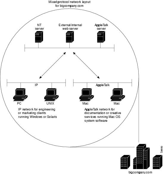
Sometimes an enterprise conducts its daily business operations across internal mixed protocol environments. (See Figure 7 and Table 1.) For example, an enterprise might deploy an IP base across the entire intranet while still allowing file sharing with other protocols such as AppleTalk and AppleTalk Remote Access (ARA).
Figure 7 Large Enterprise with a Multiprotocol Network
Enterprise Network Topology
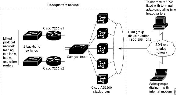
Figure 8 shows a sample enterprise network, which supports 10,000 registered token card holders. Some registered users might use their access privileges each day, while others might use their access privileges very infrequently, such as only on business trips. The dial-in access provisioned for outsiders, such as partners or vendors, is supported separately in a firewalled setup.
Five Cisco AS5300 access servers are positioned to provide 250 dial-in ports for incoming modem calls. A Catalyst 1900 is used as a standalone switch to provide Ethernet switching between the Cisco AS5300 access servers and the 100BASET interfaces on the backbone routers. Two Cisco 7200 series routers are used to reduce the processing workload on the access servers and provide access to the company's backbone. If the Cisco 7200 series routers were not used in the network solution, the Cisco AS5300 access servers could not update routing tables, especially if 20 to 30 additional routers existed on the company's backbone. Two additional backbone switches are used to provide access to the company network.
Note
Figure 8 Sample Enterprise Network Topology
If you are setting up dial-in access for remote terminal adapters, the settings configured on the terminal adapters must match the setting on the access server or router. Depending on your business application, terminal adapters can operate in many different modes. (See Table 2.)
Mixed Protocol Dial-In Scenarios
The examples in the following sections are intended to run on each network device featured in Figure 8, which allows remote users to dial in to a mixed protocol environment:
•
•
•
Note
Cisco 7200 #1 Backbone Router
The following configuration runs on the router labeled Cisco 7200 #1 in Figure 8. Fast Ethernet interface 0/0 connects to the corporate backbone switch. Fast Ethernet interface 1/0 connects to the Catalyst 1900 switch, which in turn connects to the Cisco AS5300 access servers.
version xx.xno service udp-small-serversno service tcp-small-servers!hostname bbone-dial1!aaa new-modelaaa authentication login default localaaa authentication login console enable!username admin password cisco!boot system flash slot0:enable secret <password>appletalk routingipx routing!interface FastEthernet0/0ip address 10.0.1.52 255.255.255.192appletalk cable-range 1000-1000appletalk zone Networking Infrastructureipx network 1000!interface FastEthernet1/0ip address 10.1.1.2 255.255.255.224no ip redirectsappletalk cable-range 7650-7650 7650.1appletalk zone Dial-Up Netipx network 7650!standby ip 10.1.1.1standby priority 101standby preempt!router eigrp 109redistribute staticnetwork 10.0.0.0no auto-summary!ip classlessip http serverno logging console!ip route 10.1.2.0 255.255.255.192 10.1.1.10!line con 0login authentication console!line vty 0 4login authentication defaultendCisco 7200 #2 Backbone Router
The following configuration runs on the router labeled Cisco 7200 #2 in Figure 8. Fast Ethernet interface 0/0 connects to the corporate backbone switch. Fast Ethernet interface 1/0 connects to the Catalyst 1900 switch, which in turn connects to the Cisco AS5300 access servers.
version xx.xno service udp-small-serversno service tcp-small-servers!hostname bbone-dial2!aaa new-modelaaa authentication login default localaaa authentication login console enable!username admin password cisco!boot system flash slot0:enable secret <password>appletalk routingipx routing!interface FastEthernet0/0ip address 10.0.1.116 255.255.255.192appletalk cable-range 1001-1001appletalk zone Networking Infrastructureipx network 1001!interface FastEthernet1/0ip address 10.1.1.3 255.255.255.224no ip redirectsappletalk cable-range 7650-7650 7650.2appletalk zone Dial-Up Netipx network 7650!standby ip 10.1.1.1!router eigrp 109redistribute staticnetwork 10.0.0.0no auto-summary!ip classlessip http serverno logging console!ip route 10.1.2.0 255.255.255.192 10.1.1.10!line con 0login authentication console!line vty 0 4login authentication console!end 4Cisco AS5300 Universal Access Server
The following configuration runs on each Cisco AS5300 access server in the stack group shown in Figure 8:
version xx.xservice timestamps debug datetime msecservice timestamps log datetime msecservice password-encryptionno service udp-small-serversno service tcp-small-servers!appletalk routingipx routingappletalk virtual net 7651 Dial-Up Netarap network 7652 Dial-Up Net!hostname NAS!aaa new-modelaaa authentication login default localaaa authentication login console enableaaa authentication login vty localaaa authentication login dialin localaaa authentication ppp default localaaa authentication ppp dialin if-needed localaaa authentication arap default auth-guest localenable secret cisco!username admin password ciscousername pcuser1 password mypassisdn switch-type primary-5ess!controller T1 0framing esfclock source line primarylinecode b8zspri-group timeslots 1-24!controller T1 1framing esfclock source line secondarylinecode b8zspri-group timeslots 1-24!interface loopback 0ip address 10.1.2.0 255.255.255.192ipx network 7651!interface Ethernet0ip address 10.1.1.10 255.255.255.0appletalk cable-range 7650appletalk zone Dial-Up-Netipx network 7650!interface Serial0no ip addressshutdown!interface Serial1no ip addressshutdown!interface Serial0:23no ip addressencapsulation pppisdn incoming-voice modemdialer rotary-group 0dialer-group 1no fair-queueno cdp enable!interface Serial1:23no ip addressencapsulation pppisdn incoming-voice modemdialer rotary-group 0dialer-group 1no fair-queueno cdp enable!interface Group-Async1ip unnumbered Ethernet0encapsulation pppasync mode interactivepeer default ip address pool dialin_poolappletalk client-modeipx ppp-clientno cdp enableppp authentication chap pap dialingroup-range 1 48!interface Dialer0ip unnumbered Ethernet0no ip mroute-cacheencapsulation ppppeer default ip address pool dialin_poolipx ppp-clientappletalk client-modedialer in-banddialer-group 1no fair-queueno cdp enableppp authentication chap pap dialinppp multilink!ip local pool dialin_pool 10.1.2.1 10.1.2.62ip default-gateway 10.1.1.1ip classlessip route 0.0.0.0 0.0.0.0 10.1.1.1!dialer-list 1 protocol ip permit!async-bootp dns-server 10.1.0.40 10.1.0.170async-bootp nbns-server 10.0.235.228 10.0.235.229!xremote buffersize 72000xremote tftp host 10.0.2.74!line con 0login authentication consoleline 1 48autoselect pppautoselect during-loginautoselect araparap enablearap authentication defaultarap timelimit 240arap warningtime 15login authentication dialinmodem DialInterminal-type dialupline aux 0login authentication consoleline vty 0 4login authentication vtytransport input telnet rlogin!endCisco and the Cisco Logo are trademarks of Cisco Systems, Inc. and/or its affiliates in the U.S. and other countries. A listing of Cisco's trademarks can be found at www.cisco.com/go/trademarks. Third party trademarks mentioned are the property of their respective owners. The use of the word partner does not imply a partnership relationship between Cisco and any other company. (1005R)
Any Internet Protocol (IP) addresses and phone numbers used in this document are not intended to be actual addresses and phone numbers. Any
examples, command display output, network topology diagrams, and other figures included in the document are shown for illustrative purposes
only. Any use of actual IP addresses or phone numbers in illustrative content is unintentional and coincidental.

© 2001--2009 Cisco Systems, Inc. All rights reserved.