- はじめに
- Cisco WAAS の概要
- WAAS ネットワークの計画
- デバイス グループとデバイス位置の使用
- AppNav の設定
- 代行受信の設定
- ネットワーク設定の構成
- 管理ログインの認証、許可、およびアカウンティングの設定
- 管理者ユーザ アカウントおよびグループの作成と管理
- Cisco WAAS デバイス用の IP アクセス コントロール リストの作成および管理
- その他のシステム設定の構成
- ファイル サービスの設定
- ファイル サービスの設定
- 解析モジュールの設定
- WAAS システムの保守
- WAAS ネットワークのモニタリングおよびトラブルシューティング
- SNMP モニタリングの設定
- 定義済み最適化ポリシー
- トランザクション ログ形式
- Index
- 代行受信方式に関する情報
- WCCP 代行受信に関する情報
- ルータでの高度な WCCP 機能の設定
- WAE 上での WCCP の設定
トラフィック代行受信の設定
この章では、IP および TCP ヘッダー情報に基づいて IP ベース ネットワークの TCP トラフィックの代行受信を設定する方法と、Cisco Wide Area Application Services(WAAS)デバイスにトラフィックをリダイレクトする方法について説明します。この章では、Web Cache Communication Protocol(WCCP)、ポリシーベース ルーティング(PBR)、Cisco Wide Area Application Engine(WAE)への透過的なトラフィック リダイレクションのためのインライン モード、AppNav コントローラ と一緒に使用する AppNav コントローラ モードの使用方法について説明します。

(注![]() ) この章では、ネットワークに存在する WAAS Central Manager と Wide Area Application Engine(WAE)を総称する用語として「WAAS デバイス」を使用します。WAE という用語は、WAE および Cisco Wide Area Virtualization Engine(WAVE)アプライアンス、WAE ネットワーク モジュール(NME-WAE ファミリのデバイス)、WAAS を実行している SM-SRE モジュール、および vWAAS インスタンスを指します。
) この章では、ネットワークに存在する WAAS Central Manager と Wide Area Application Engine(WAE)を総称する用語として「WAAS デバイス」を使用します。WAE という用語は、WAE および Cisco Wide Area Virtualization Engine(WAVE)アプライアンス、WAE ネットワーク モジュール(NME-WAE ファミリのデバイス)、WAAS を実行している SM-SRE モジュール、および vWAAS インスタンスを指します。
この章の手順を実行する前に、『Cisco Wide Area Application Services Quick Configuration Guide』の説明に従って、WAAS ネットワークの基本的な初期インストールおよび設定を完了する必要があります。この章の CLI コマンドの詳細なコマンド構文情報については、『Cisco Wide Area Application Services Command Reference』を参照してください。WCCP の詳細については、Cisco IOS マニュアルを参照してください。
代行受信方式に関する情報
WAAS ネットワークでは、最適化、冗長性の除去、および圧縮のために、ブランチ オフィスのクライアントとデータセンターのサーバ間のトラフィックを WAE へリダイレクトできます。トラフィックは、ルータまたは AppNav コントローラ(ANC)に設定されているポリシーに基づいて、透過的に代行受信されて WAE にリダイレクトされます。要求をローカル WAE に透過的にリダイレクトするネットワーク要素として WCCP バージョン 2 または PBR を使用するルータを使用すれば、たとえば、Catalyst 6500 シリーズの Content Switching Module(CSM)または Application Control Engine(ACE)など、トラフィックをローカル WAE またはレイヤ 4 ~ レイヤ 7 のスイッチにリダイレクトできます。あるいは、Cisco WAE Inline Network Adapter またはインターフェイス モジュールが搭載された WAE でインライン モードを使用することによって、トラフィックを直接に代行受信できます。Cisco AppNav コントローラ インターフェイス モジュールが搭載されている場合、WAVE アプライアンスまたはクラスタは WCCP またはインライン モードでネットワーク トラフィックを代行受信し、フロー ポリシーに基づいて、最適化のためにそのトラフィックを 1 つ以上の WAE(WAAS ノード)に分散します。
表 5-1 に、WAAS でサポートされる透過トラフィック代行受信方式を示します。
|
|
|
|---|---|
アプリケーション トラフィックと Common Internet File System(SMB)トラフィックの透過的な代行受信に使用します。ブランチ オフィスとデータセンターで、トラフィックを WAAS デバイスに透過的にリダイレクトするために使用します。WCCP 対応ルータまたはレイヤ 3 スイッチが、透過的にトラフィックを代行受信し、ローカル WAE または ANC にリダイレクトします。 ブランチ オフィスのルータと WAE およびデータセンターのルータと WAE で、WCCP を設定する必要があります。詳細については、次の項を参照してください。 |
|
ブランチ オフィスで、広域アプリケーションの最適化に使用します。ブランチ オフィスのルータは、PBR を使用してクライアントとサーバ両方のトラフィックを透過的に代行受信し、同じブランチ オフィスに存在する WAE へルーティングするように設定されます。 データセンターでは、データセンター アプリケーションの最適化に使用します。データセンター ルータやレイヤ 3 スイッチは、透過的に代行受信したり、クライアントとサーバをデータセンター内で WAE にルーティングしたりするために、PBR を使用するように設定できます。ただし、PBR は WCCP が行うような、複数の WAE 間のロード バランシングをサポートしません。PBR は、Cisco CSM や ACE などのロード バランサを使用した場合でもロード バランシングをサポートしません。ポリシー ベース ルーティング代行受信の使用を参照してください。 |
|
WAE は、物理的かつ透過的にトラフィックをクライアントとルータの間で代行受信します。このモードを使用するには、Cisco WAE Inline Network Adapter、Cisco インターフェイス モジュール、または Cisco AppNav コントローラ インターフェイス モジュールが搭載された WAAS デバイスを使用する必要があります。インライン モード代行受信の使用を参照してください。 |
|
|
(注 |
|
AppNav 導入の一部であり、かつ AppNav クラスタの WAAS ノードとして設定されている WAE の場合は、WAE を設定して appnav-controller 代行受信方式を使用する必要があります。この設定により、WAE におけるトラフィックの受信、および AppNav コントローラにより代行受信され、分散されるトラフィックの最適化が可能になります。AppNav 代行受信の設定 を参照してください。 |
|
データセンターの最適化のために、Cisco Application Control Engine(ACE)または Catalyst 6500 シリーズ Content Switching Module(CSM)がデータセンターにインストールされています。ACE と CSM は、データセンター内の複数の WAE 間のトラフィックの代行受信とロード バランシングの両方を行うことができます。 |
(注![]() ) ISR-WAAS デバイスは AppNav コントローラの代行受信方式だけをサポートします。
) ISR-WAAS デバイスは AppNav コントローラの代行受信方式だけをサポートします。
WAE デバイスがトラフィックの最適化を阻止するファイアウォールの背後にある場合、WAN 経由のピア WAE 間の通信に directed モードを使用できます。
WCCP 代行受信に関する情報
WAAS ソフトウェアは、WCCP 標準バージョン 2 を使用して、リダイレクションを実行します。WCCP バージョン 2 の主な機能は、次のとおりです。
- WCCP サービスあたり最大 32 の WAE
- WCCP サービスあたり最大 32 台のルータ
- プロトコル パケットの認証
- 非 HTTP トラフィックのリダイレクション
- パケット リターン(総称ルーティング カプセル化(GRE)を含む。WAE は、リダイレクトされたパケットを拒否し、転送するルータへ戻すことができる)
- マスキングによるロード バランシングの改善
- 複数の転送方式
- サービス グループ内でのパケット分散方式のネゴシエーション
- WAE とサービス グループ間のコマンドとステータスの交換
(注![]() ) WCCP は、IPv4 ネットワークだけで動作します。
) WCCP は、IPv4 ネットワークだけで動作します。
WAAS ソフトウェアは、WCCP TCP 無差別モード サービスをサポートしています(デフォルトではサービス 61 および 62。これらのサービス ID は設定可能です)。この WCCP サービスでは、ルータと WAE で WCCP バージョン 2 が動作している必要があります。
TCP 無差別モード サービスとは、すべての TCP トラフィックを代行受信し、ローカル WAE へリダイレクトする WCCP サービスです。
また、WAAS ソフトウェアは、サービス パスワード、WAE フェールオーバー、代行受信 ACL、およびもサポートしています。
多くの Cisco ルータ/スイッチは、設定により WCCP バージョン 2 サポートを有効にして、WAAS デバイスとともに使用できます。
2500、2600、および 3600 ルータを含む多数の従来の Cisco ルータは、Integrated Services Router(ISR)モデル 2800 および 3800 などの新しいルーティング プラットフォームに比べ、処理性能とメモリ レベルがはるかに劣っています。そのため、WCCPv2 または PBR を使用すると、ルータの CPU 使用率が高くなり、動作が不安定になる場合があります。これらのルータで動作するように WAAS を設定できますが、新しいルーティング プラットフォームと同じレベルのパフォーマンスや拡張性は実現できません。Cisco ISR は、ブランチ オフィス用のルーティング プラットフォームとして最適です。
WAE がサービス グループから除外されるなど動作が不安定になる場合は、ユーザ、サーバ、WAE、および WAN と接続するルータのすべての物理インターフェイスで、公平キュー方式、重み付き公平キュー方式、または速度制限を有効にしてください。公平キュー方式はサブインターフェイスでは設定できず、入力と出力の両方の物理インターフェイスで設定する必要があります。LAN や WAN インターフェイスで、公平キュー方式以外のキュー方式がすでに設定されており同様の公平さを提供する場合は、それで十分です。
さらに、ルータの LAN 側インターフェイスで受信できる帯域幅を制限すると、ルータのインターフェイス キューの混雑が軽減され、パフォーマンスが向上し、CPU 使用率が低下します。ルータの最大インターフェイス帯域幅を WAN 帯域幅キャパシティの 10 倍以下に設定します。たとえば、WAN リンクが T1 である場合、LAN インターフェイスと WAE の LAN インターフェイス帯域幅を 10 X T1 = 10 X 1.544 Mbps(約 15 Mbps)に制限する必要があります。詳細については、Cisco IOS マニュアルを参照してください。
WCCP を設定するためのガイドライン
WCCP バージョン 2 を使用して WAE で透過的なリダイレクションを設定するときは、次のガイドラインに従ってください。
- 可能な場合は常に、着信インターフェイスでパケットを代行受信し、リダイレクトします。
- WAE をクライアントおよびサーバとして同一の VLAN またはサブネットに配置する場合は、WCCP GRE または汎用 GRE を出力方式として使用します。IP 転送出力方式を使用する場合は、このトポロジは利用できません。
- ブランチ オフィスの WAE は、パケットを暗号化したり圧縮したりせずに、内部ネットワーク アドレス変換(NAT)ファイアウォール(存在する場合)の一部として動作する必要があります。
- Catalyst 6500 シリーズ スイッチまたは Cisco 7600 シリーズ ルータを使用している場合は、パケット転送方式としてレイヤ 2 リダイレクションを使用します。他の Cisco ルータを使用している場合は、レイヤ 3 GRE パケット リダイレクションを使用します。
- ホットスタンバイ ルータ プロトコル(HSRP)と WCCP を使用する場合、WAE のデフォルト ゲートウェイとして HSRP または仮想ルータ冗長プロトコル(VRRP)を設定し、HSRP グループのルータのプライマリ アドレスに WAE WCCP ルータリストを設定します。
- CEF は、WCCP に必要であり、ルータで有効になっている必要があります。
- ネットワークのクライアント側にブランチ オフィスの WAE を配置し、ルータを経由するクライアント側のパケット数を最小限に抑えます。
- サービス拒絶(DoS)攻撃を避けるため、WCCP パスワードを使用します。詳細については、ルータ上のサービス グループ パスワードの設定を参照してください。
- 新たに実装した場合は、WCCP リダイレクト リストを使用して、クライアントまたはサーバの読み込みを制限します。詳細については、ルータ上の IP アクセス リストの設定を参照してください。
- WAE が、複数の WCCP 対応ルータからリダイレクトされたパケットを受け入れるように設定します。
- 基本 WCCP を設定するには、ネットワーク内の少なくとも 1 台のルータと、トラフィックをリダイレクトしたい WAE または ANC で、WCCP サービスを有効にします。WAE を起動し稼働させるために、使用可能なすべての WCCP 機能またはサービスをすべて設定する必要はありません。ブランチ オフィスとデータセンターのルータおよび WAE で基本的な WCCP 設定を完了する方法の例については、『 Cisco Wide Area Application Services Quick Configuration Guide 』を参照してください。
- WCCP バージョン 1 は Web トラフィック(ポート 80)しかサポートしていないため、ルータと WAE が WCCP バージョン 1 の代わりに WCCP バージョン 2 を使用するように設定します。
- ルータで WCCP を有効にしたら、『 Cisco Wide Area Application Services Quick Configuration Guide 』の説明に従って、ルータと WAE で TCP 無差別モード サービスを設定します。サービス ID は、WAE で設定できます。異なるファーム内の WAE は別のサービス ID を使用することがあるため、デフォルトの 61 と 62 とは異なる数字のペアを選択して、ルータで複数の WCCP ファームをサポートできます。ルータの設定では、サポートされている各ファーム内の WAE で設定した ID と一致する WCCP サービス ID を使用する必要があります。
- WAE を TCP 無差別モードで機能させるには、WAE で WCCP バージョン 2 サービス 61 および 62 を使用します(サービス ID は設定可能です)。この 2 つの WCCP サービスは、WAE では標準名の tcp-promiscuous で表されます。
- CLI コマンドを使用して、ルータおよび WAE の両方、または ANC で基本的な WCCP を設定します。また、WCCP 用のルータを設定する CLI コマンドや、WAE または ANC で基本的な WCCP を設定する WAAS Central Manager を使用することもできます。『 Cisco Wide Area Application Services Quick Configuration Guide 』にある設定例では、WAE または ANC で基本的な WCCP を設定するために、 wccp グローバル設定コマンドが使用されています。
最初のブランチ オフィスの WAE とデータセンターの WAE では、『 Cisco Wide Area Application Services Quick Configuration Guide 』の説明に従って、WAAS CLI を使用して WCCP の基本的な初期設定を完了することを推奨します。 WCCP 透過リダイレクションが正常に動作していることを確認したら、WAAS Central Manager を使用してこの基本的な WCCP 設定を変更したり、ロード バランシングなど、WAE 用に追加の WCCP 設定を行うことができます。詳細については、WAE 上での WCCP の設定を参照してください。ルータ上の基本的な WCCP を構成したら、ルータでの高度な WCCP 機能の設定の説明に従って、ルータ上の高度な WCCP 機能を構成できます。
- WAE 間の一貫性を確保するために、1 台のデバイスで WCCP を設定し、WCCP 設定ウィンドウ内で [Copy Settings] タスクバー アイコンを使用して、ネットワークの他のデバイスに設定をコピーすることを推奨します。WCCP 設定は、ファームまたはサービス グループごとに異なる必要がある場合があるため、同じ WCCP サービス ファーム、AppNav コントローラ グループ(ANCG)、または WAAS ノード グループ(WNG)の WAE にのみ設定をコピーする必要があります。
- 新規ルータを既存の WCCP ルータ ファームまたは WCCP サービス グループに追加すると、新規ルータは既存の接続をリセットします。WCCP がパス リダイレクションおよび割り当てを再確立するまで、パケットはクライアントに(予期したとおりに)直接送信されます。
- ルータは、WAE に設定されているリダイレクトおよび返信方式をサポートしている必要があります。設定されている方式がルータでサポートされていない場合、WAE は WCCP ルータ ファームに参加しません。ファーム内で異なるルータが組み合されている場合、設定されている方式をサポートするルータだけがファームに参加します。
- WAE で設定した割り当て方式がルータによってサポートされている場合に限り、WAE は WCCP ファームに参加します。(バージョン 4.4.1 以降では、厳格な割り当て方式が常に適用されます)。
- WAE は、ファームに設定されているすべてのルータに認識されている場合に限り、WCCP ファームに参加します。いずれかのルータにリンク障害があれば、ファームは再設定され、WAE はファームから除去されます。
- WCCP ファーム内のすべての WAE は、WCCP サービス ID と同じペアを使用する必要があります(デフォルトは 61 と 62 です)。これらの ID は、そのファームをサポートしているすべてのルータで一致している必要があります。WCCP サービス ID が異なる WAE は、ファームへの参加が許可されず、アラームが生成されます。同様に、ファーム内のすべての WAE は、障害検出タイムアウトに対して同じ値を使用する必要があります。設定した値が一致していない場合は、アラームが生成されます。
- 仮想ルーティングおよび転送(VRF)対応の WCCP スケーラビリティは、次のとおりです。
–![]() 単一の VRF インスタンスによってサポートされる WAE の最大数は 32 です。
単一の VRF インスタンスによってサポートされる WAE の最大数は 32 です。
–![]() ルータによってサポートされる VRF インスタンスの最大数は、ルータによって異なります。
ルータによってサポートされる VRF インスタンスの最大数は、ルータによって異なります。
–![]() VRF 対応の WCCP は、Cisco IOS ソフトウェアの特定のリリースだけでサポートされます。ルータが、VRF 対応 WCCP をサポートする Cisco IOS ソフトウェアのリリースを実行していることを確認します。
VRF 対応の WCCP は、Cisco IOS ソフトウェアの特定のリリースだけでサポートされます。ルータが、VRF 対応 WCCP をサポートする Cisco IOS ソフトウェアのリリースを実行していることを確認します。
–![]() 各 VRF インスタンスには、独立した割り当て、リダイレクション、および返信方式があります。
各 VRF インスタンスには、独立した割り当て、リダイレクション、および返信方式があります。
- WAAS AppNav 導入では、トラフィックを代行受信して、最適化される WAAS ノード(WN)に分散する ANC デバイスのみで WCCP を有効にします。appnav-controller 代行受信方式を使用して、AppNav クラスタの一部である WN を設定します。
- WCCP L2 が導入されているネットワークで廃棄されたパケットの数を減らすには、WAAS Central Manager を使用して WN の最大セグメント サイズ(MSS)を 1406 バイトに設定することを推奨します。MSS 変更の詳細については、12 章「アプリケーション アクセラレーションの設定」の アクセラレーション TCP 設定の変更 を参照してください。
ファイル サーバ アクセス方式に関するガイドライン
一部のファイル サーバには複数のネットワーク インターフェイスがあり、複数の IP アドレスを通じて到達できます。このようなサーバの場合は、ブランチ オフィスの WAE の WCCP 受容リストに、使用できるすべての IP アドレスを追加する必要があります。このようにすると、クライアントは、登録されていない IP アドレスを使用してブランチ オフィスの WAE をバイパスすることがなくなります。WAE Device Manager GUI は、すべての IP アドレスを表示します。
一部のファイル サーバには、複数の NetBIOS 名と、ただ 1 つの IP アドレスがあります。このようなサーバの場合は、クライアントが UNC パス内の IP アドレス(つまり、\\server\share でなく \\IP_address\share)を使用して接続すると、WAAS は、WAE Device Manager GUI でサーバ リストからこの IP アドレスと一致する最初の NetBIOS 名を選択します。WAAS は、その名前を使用して、データセンターの WAE とファイル サーバ間の NetBIOS ネゴシエーションを実行し、キャッシュにリソースを作成します。ファイル サーバが複数の NetBIOS 名を使用して(設定が異なる場合がある)仮想サーバを表し、プライマリ サーバ名として識別される 1 つの NetBIOS 名を持つ場合は、サーバ リストの先頭にその名前を置きます。
ルータでの高度な WCCP 機能の設定
この項では、WAAS ネットワークで要求を WAE へ透過的にリダイレクトする WCCP 対応ルータで、高度な WCCP バージョン 2 機能を設定する方法について説明します。
- WCCP サービス グループをサポートするためのルータの設定に関する情報
- ルータ上の IP アクセス リストの設定
- ルータ上のサービス グループ パスワードの設定
- ルータ上のループバック インターフェイスの設定
- WCCP コントロール パケット向けのルータ QoS の設定
(注![]() ) この項の手順を実行する前に、『Cisco Wide Area Application Services Quick Configuration Guide』の説明に従って、基本的な WCCP 用にルータを設定しておく必要があります。
) この項の手順を実行する前に、『Cisco Wide Area Application Services Quick Configuration Guide』の説明に従って、基本的な WCCP 用にルータを設定しておく必要があります。
WCCP サービス グループをサポートするためのルータの設定に関する情報
WCCP バージョン 2 を利用すると、WAE グループまたは ANC グループ内の 1 組のブランチ オフィスの WAE を複数のルータに接続することができます。グループ内の WAE、および同じ WCCP サービスを稼働している WAE グループに接続されている WCCP バージョン 2 対応ルータのことを「 サービス グループ 」と呼びます。
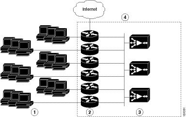
WCCP バージョン 2 対応ルータは、ブランチ オフィスの WAE との通信を通じて、使用できるブランチ オフィスの WAE を識別します。ルータとブランチ オフィスの WAE は相互に識別し、WCCP バージョン 2 を使用してサービス グループを形成します図 5-1を参照してください。
WAAS AppNav 導入では、ANC のみがサービス グループに含まれます。ルータは最適化を行っている WAE(WN)にトラフィックを直接送信しません。代わりに、ANC が、最適化を行っている WN に WAAS ネットワーク内のトラフィックを分散します。
図 5-1 WCCP バージョン 2 でのサービス グループ
|
|
|
||
|
|
|
ブランチ オフィスの WAE のグループが存在する場合は、すべての WCCP バージョン 2 対応ルータによって認識され、最も小さい IP アドレスを持つ WAE がブランチ オフィスのリード WAE になります。
次の手順で、サービス グループ内の 1 つのブランチ オフィスの WAE をリードとして指定する方法を説明します。
1.![]() 各ブランチ オフィスの WAE に、WCCP 対応ルータのリストが設定されます。
各ブランチ オフィスの WAE に、WCCP 対応ルータのリストが設定されます。
複数の WCCP 対応ルータがグループにサービスを提供できます(最大 32 台のルータを指定できます)。サービス グループ内の使用可能なルータはいずれも、グループ内の各ブランチ オフィスの WAE にパケットをリダイレクトできます。
2.![]() 各ブランチ オフィスの WAE は、自身が存在することを、ルータ リストの各ルータに通知します。ルータは、サービス グループ内のブランチ オフィスの WAE のビューとともに応答を返します。
各ブランチ オフィスの WAE は、自身が存在することを、ルータ リストの各ルータに通知します。ルータは、サービス グループ内のブランチ オフィスの WAE のビューとともに応答を返します。
3.![]() グループ内のすべてのブランチ オフィスの WAE の間でビューの一貫性が確保されると、1 台のブランチ オフィスの WAE がブランチ オフィスのリード WAE として指定され、パケットをリダイレクトするために WCCP 対応ルータを配置する必要があるという内容のポリシーが設定されます。
グループ内のすべてのブランチ オフィスの WAE の間でビューの一貫性が確保されると、1 台のブランチ オフィスの WAE がブランチ オフィスのリード WAE として指定され、パケットをリダイレクトするために WCCP 対応ルータを配置する必要があるという内容のポリシーが設定されます。
ブランチ オフィスのリード WAE は、グループのブランチ オフィスの WAE にトラフィックを割り当てる方法を指定します。グループの WCCP 対応ルータがパケットをリダイレクトし、グループ内のブランチ オフィスの WAE がそれぞれの負荷をより適切に管理できるように、割り当て情報は指定されたブランチ オフィスのリード WAE からサービス グループ全体に渡されます。
WCCP は、サービス グループを使用して、グループ内の WCCP バージョン 2 対応ルータとブランチ オフィスの WAE 用の WAAS サービスを定義します。また、WCCP は、リアルタイムでこれらのグループへクライアント要求をリダイレクトします。
同じ WCCP サービス グループのメンバーとして設定され、リダイレクトされたトラフィックを受信するポートはすべて、次の特性を共有します。
- ポートはすべて、WAAS Central Manager(WAE 上での WCCP の設定および WCCP 設定の表示)または WAAS CLI( wccp service-number mask グローバル コンフィギュレーション コマンド)で設定されているとおり、同じハッシュまたはマスク パラメータを持ちます。
- 個々のポートの WCCP バージョン 2 サービスを、個別に停止または開始することはできません(WCCP バージョン 2 の制限)。
ルータ上の IP アクセス リストの設定
オプションで、ルータに定義されたアクセス コントロール リスト(ACL)に基づいて、トラフィックを WAE からリダイレクトするようにルータを設定できます。これらのアクセス リストのことを「リダイレクト リスト」と呼びます。
(注![]() ) 可能な場合は WCCP 対応ルータ上のリダイレクト リストを使用することを推奨します。トラフィック代行受信を制御するには、これが最も効率的な方法です。WAE 上では固定バイパス リストまたは代行受信 ACL も設定できますが、これらの 2 つの内、代行受信 ACL を使用することを推奨します。これは、代行受信 ACL の方が柔軟性が高く、パススルー接続についてより優れた統計情報が得られるためです。WAE の代行受信 ACL を設定する方法の詳細については、代行受信アクセス コントロール リストの設定を参照してください。固定バイパス リストの設定方法については、WAE 用の固定バイパス リストの設定を参照してください。Chapter9, “Cisco WAAS デバイス用の IP アクセス コントロール リストの作成および管理” で説明されているとおり、WAE にインターフェイス ACL を設定して、WAE へのアクセスを制御できます。
) 可能な場合は WCCP 対応ルータ上のリダイレクト リストを使用することを推奨します。トラフィック代行受信を制御するには、これが最も効率的な方法です。WAE 上では固定バイパス リストまたは代行受信 ACL も設定できますが、これらの 2 つの内、代行受信 ACL を使用することを推奨します。これは、代行受信 ACL の方が柔軟性が高く、パススルー接続についてより優れた統計情報が得られるためです。WAE の代行受信 ACL を設定する方法の詳細については、代行受信アクセス コントロール リストの設定を参照してください。固定バイパス リストの設定方法については、WAE 用の固定バイパス リストの設定を参照してください。Chapter9, “Cisco WAAS デバイス用の IP アクセス コントロール リストの作成および管理” で説明されているとおり、WAE にインターフェイス ACL を設定して、WAE へのアクセスを制御できます。
ルータに設定されているリダイレクト リストのプライオリティが最も高くなり、固定バイパス リストまたは WAE 上の代行受信 ACL が続きます。WAE で設定される代行受信 ACL は、WAE で定義されているアプリケーション定義ポリシーよりも優先されます。
WCCP バージョン 2 対応ルータには、WAE への TCP トラフィックのリダイレクションを許可または拒否するためのアクセス リストを設定できます。次の例では、ルータは、次の条件に一致するトラフィックを WAE へリダイレクトしません。
Router(config)# ip wccp 61 redirect-list 120
Router(config)# ip wccp 62 redirect-list 120
Router(config)# access-list 120 deny ip host 10.1.1.1 any
Router(config)# access-list 120 deny ip any host 10.1.1.1
Router(config)# access-list 120 deny ip any host 10.255.1.1
Router(config)# access-list 120 deny ip host 10.255.1.1 any
Router(config)# access-list 120 permit ip any
明示的に許可されないトラフィックは、暗黙的にリダイレクションが拒否されます。 access-list 120 permit ip any コマンドは、明示的にすべてのトラフィック(任意の送信元から任意の宛先宛て)の WAE へのリダイレクションを許可しています。コマンドが入力された順番で条件に照合されるため、グローバル permit コマンドが最後に入力するコマンドとなります。
パケットのリダイレクションをアクセス リストに一致したパケットだけに制限するには、ip wccp redirect-list グローバル コンフィギュレーション コマンドを使用します。このコマンドを使用して、どのパケットを WAE へリダイレクトする必要があるかを指定します。
WCCP が有効になっていても、ip wccp redirect-list コマンドを使用しない場合は、WCCP サービスの条件に一致するすべてのパケットが WAE へリダイレクトされます。ip wccp redirect-list コマンドを指定すると、アクセス リストに一致するパケットだけがリダイレクトされます。
WCCP を使用して WAE への要求のリダイレクションを開始するために必要なコマンドは、ip wccp グローバル コンフィギュレーション コマンドと ip wccp redirect インターフェイス コンフィギュレーション コマンドだけです。WCCP 対応ルータのインターフェイスが、該当する発信パケットかどうかをチェックし、パケットを WAE へリダイレクトするように指定するには、 ip wccp redirect インターフェイス コンフィギュレーション コマンドを使用します。ip wccp コマンドが有効でも、ip wccp redirect コマンドが無効の場合、WCCP 対応ルータは WAE を認識しますが、この WAE を使用しません。
名前または番号でアクセス リストを指定するには、グループ メンバーシップの基準を定義する ip wccp group-list グローバル コンフィギュレーション コマンドを使用します。次の例では、 access-list 1 permit 10.10.10.1 コマンドを使用して、WCCP サービス グループへの参加を許可する WAE の IP アドレスを定義しています。
Router(config)# ip wccp 61 group-list 1
Router(config)# ip wccp 62 group-list 1
Router(config)# access-list 1 permit 10.10.10.1

ヒント![]() WCCP サービス ファームに複数の WAE が存在している場合は、ロード バランシング割り当てによって、パケット(管理トラフィックなど)は WAE デバイス自体に送信され、そこからファーム内の別の WAE にリダイレクトされる可能性があり、それによってパフォーマンスが低下します。この状況を避けるため、WAE IP アドレスに送信されるトラフィックをリダイレクトから除外する WCCP リダイレクト リストを設定することを推奨します。
WCCP サービス ファームに複数の WAE が存在している場合は、ロード バランシング割り当てによって、パケット(管理トラフィックなど)は WAE デバイス自体に送信され、そこからファーム内の別の WAE にリダイレクトされる可能性があり、それによってパフォーマンスが低下します。この状況を避けるため、WAE IP アドレスに送信されるトラフィックをリダイレクトから除外する WCCP リダイレクト リストを設定することを推奨します。
アクセス リストの詳細については、Cisco IOS IP アドレッシングおよびサービスのマニュアルを参照してください。
ルータ上のサービス グループ パスワードの設定
セキュリティを目的として、WCCP バージョン 2 対応ルータとそれにアクセスする WAE に、サービス パスワードを設定できます。正しいパスワードが設定されたデバイスだけに、WCCP サービス グループへの参加が許可されます。
WCCP 対応ルータのグローバル設定モードから、次のコマンドを入力して、ルータの TCP 無差別モード サービスに対してサービス グループ パスワードを指定します。
[0-7] password
[0-7] password
必須の password 引数は、WCCP バージョン 2 対応のルータに、指定したサービス グループから受信したメッセージに MD5 認証を適用するよう指示する文字列です。認証で受け入れられなかったメッセージは廃棄されます。 0 ~ 7 は、パスワードの暗号化に使用される HMAC MD5 アルゴリズムを示すオプションの値です。この値は、WAE の暗号化パスワードが作成されたときに生成されます。7 の値を推奨します。オプションの password 引数は、ルータと WAE 間の接続のセキュリティを確立するために、HMAC MD5 値と組み合わされるオプションのパスワード名です。
WAAS Central Manager を使用して WAE上のサービス グループ パスワードを指定する方法については、WAE 上での WCCP の設定および WCCP 設定の表示を参照してください。
ルータ上のループバック インターフェイスの設定
ルータのループバック インターフェイスのなかで最も大きい IP アドレスが、WAE へのルータの識別に使用されます。
次の例では、ループバック インターフェイスを設定し、コンフィギュレーション モードを終了し、実行コンフィギュレーションをスタートアップ コンフィギュレーションとして保存しています。
Router(config-if)# end
Router# copy running-config startup-config
WCCP コントロール パケット向けのルータ QoS の設定
WAAS は Diffserv コード ポイント(DSCP)値 192 でマーキングした WCCP コントロール パケットを送信します。(バージョン 4.2 よりも前の WAAS では、パケットはマーキングされません)ルータがこのプライオリティ値を活用するには、DSCP 値を調べて、ルータのマルチレイヤ スイッチング(MLS)の Quality of Service(QoS)ポートの信頼状態を設定し、トラフィックを分類する必要があります。ルータを適切に設定するには、WAE に接続されたインターフェイス上で、インターフェイス コンフィギュレーション モードで mls qos trust dscp コマンドを使用します。
WAE 上での WCCP の設定
- ロード バランシングと WAE に関する情報
- パケット転送方式に関する情報
- WAE 上での WCCP の設定および WCCP 設定の表示
- ANC 上での WCCP の設定および WCCP 設定の表示
- WAE 用の WCCP ルータ リストの設定および表示
- WCCP の正常なシャットダウンのための WAE の設定
- WAE 用の固定バイパス リストの設定
- 代行受信アクセス コントロール リストの設定
- WCCP 代行受信接続の出力方式の設定
(注![]() ) この項の手順を実行する前に、『Cisco Wide Area Application Services Quick Configuration Guide』の説明に従って、ルータと WAE 上の WCCP バージョン 2 と TCP 無差別モード サービスの基本的な設定など、WAAS ネットワークの初期設定が完了しているものとします。
) この項の手順を実行する前に、『Cisco Wide Area Application Services Quick Configuration Guide』の説明に従って、ルータと WAE 上の WCCP バージョン 2 と TCP 無差別モード サービスの基本的な設定など、WAAS ネットワークの初期設定が完了しているものとします。
ロード バランシングと WAE に関する情報
WCCP 対応の複数の WAE を展開して、動的なロード バランシングを実装することで、サービス グループ内の個々の WAE に転送される負荷の調整を行うことができます。WCCP 対応ルータが受信した IP パケットは、WAE へ転送する必要のある要求であるかどうかがチェックされて判断されます。パケット検査には、要求と定義されたサービス基準との照合が含まれます。これらのパケットは、どの WAE(存在する場合)がリダイレクトされたパケットを受信する必要があるかを判断するために、ルータ上の処理ルーチンへ渡されます。
(注![]() ) WAAS AppNav 導入では、ANC のみがサービス グループに含まれ、ルータによりロード バランシングが行われます。ルータは最適化を行っている WAE(WNG)にトラフィックを送信しません。代わりに、ANC が、最適化を行っている WNG にトラフィックを分散します。
) WAAS AppNav 導入では、ANC のみがサービス グループに含まれ、ルータによりロード バランシングが行われます。ルータは最適化を行っている WAE(WNG)にトラフィックを送信しません。代わりに、ANC が、最適化を行っている WNG にトラフィックを分散します。
ロード バランシングを使用すると、複数の WAE 間でトラフィックの負荷バランスを取ることができます。ロード バランシングを使用すると、過負荷の WAE から、使用可能なキャパシティを持つその他の WAE へ負荷を移動して、WAE に割り当てられている一連のハッシュ アドレス バケットを調整することができます。この技術では、ハッシュとマスキングの 2 つの割り当て方式が使用されます。
割り当て方式とは、WCCP が WAE 間に負荷を分散するために使用する方式を示します。2 つのロード バランシング割り当て方式は、ハッシュとマスキングです。マスク ロード バランシング方式が指定されていない場合は、ハッシュ ロード バランシング方式が使用されます。これは、デフォルトの方式です。
(注![]() ) WAAS AppNav 導入では、マスク割り当て方式のみがサポートされ、これがデフォルトになります。
) WAAS AppNav 導入では、マスク割り当て方式のみがサポートされ、これがデフォルトになります。
WCCP は、ハッシュ関数に基づくリダイレクションをサポートします。ハッシュ キーは、パケットの送信元または送信先 IP アドレスをベースにすることができます。WAFS の場合、ロード バランシング ハッシュは、送信元 IP アドレス(デフォルト)、送信先 IP アドレス、またはその両方に基づいています。
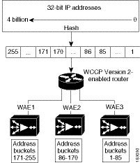
ハッシュ関数は、送信元 IP アドレスを使用して、パケットの割り当て先となるアドレス バケットを取得します。その後、この送信元アドレス バケットは、存在する WAE の数と WAE の使用状況に応じて、特定の WAE にマッピングされます(図 5-2 を参照)。
図 5-2 IP アドレスのハッシュによるロード バランシング
(注![]() ) WAE が処理しないパケットは、送信元の同じルータへ返信されます。ルータは、正式にリダイレクトされたパケットを受信した場合に、それを再度リダイレクトしてはならないことを認識します。
) WAE が処理しないパケットは、送信元の同じルータへ返信されます。ルータは、正式にリダイレクトされたパケットを受信した場合に、それを再度リダイレクトしてはならないことを認識します。
送信先 IP アドレス ハッシュは、1 つの WAE が 1 つの特定のファイル サーバだけをキャッシュするように保証します。この方式により、ローカル一貫性ディレクティブをファイル サーバの内容に安全に適用できるため(内容に他の共同作業が行われていない場合)、パフォーマンス、WAN リンク、およびディスクの使用率が向上します。ファイル サーバ上のアクティビティは一様でないため、この方式では、負荷が不均等に分散されることがあります。
送信元 IP アドレスのハッシュの方が、ブランチ オフィスの WAE 上のキャッシュ間のセッション分散に適しています。この方式は、パフォーマンス、WAN リンク、およびディスク使用率に影響する場合があります(ロード バランシングを適用するときに考慮する必要がある要因については、前の説明を参照してください)。また、クライアントの IP アドレスが変更されると(DHCP 環境で動作中に発生する場合がある)、クライアントが別のブランチ オフィスの WAE に切り替えることがあります。これにより、クライアントのワーキング セットが新しいキャッシュに取り込まれるまで、クライアントのパフォーマンスが低下することがあります。
クライアント IP アドレスに基づくハッシュは、ハッシュ キーの局所性を一切保証しません。たとえば、同じサブネットのクライアント(同じ内容を共有し、同じ内容に対して共同作業している可能性がある)に、2 つの異なるハッシュ番号が割り当てられ、それによってそれぞれ異なるブランチ オフィスの WAE にリダイレクトされる場合もあれば、異なるサブネットのクライアントに同じハッシュ番号が割り当てられ、同じブランチ オフィスの WAE にリダイレクトされる場合もあります。クライアント IP アドレスに基づくハッシュは、一貫性を保証します。たとえば、同じ IP アドレスを使用しているクライアントは、同じブランチ オフィスの WAE にリダイレクトされます。
サービス ファームの中で、使用できる WAE の間で負荷を分散するハッシュ テーブルを作成するために、リード WAE が選択されます。リード WAE は、均等にバケットを分散します。送信元 IP アドレスがハッシュされ、その結果割り当てられたバケットに従い、パケットを処理する WAE が決定されます。
WCCP は、マスク値割り当てによるリダイレクションをサポートします。この方式は、マスキングに依存して、リダイレクションに関する決定を下します。決定は、WCCP 対応ルータの特殊なハードウェア サポート機能を使用して実行されます。この方式は、ハードウェアがパケットを交換するため、非常に効率的です。
(注![]() ) マスキング方式は、Catalyst 3750、Catalyst 4500、および Catalyst 6500 シリーズ スイッチ、Cisco 7600 シリーズ ルータ、および Cisco ASR 1000 Aggregation シリーズ ルータとのロード バランシングに使用できます。また、Cisco IOS リリース 12.4(20)T 移行のリリースを実行している Cisco 2800、3800、および 7200 シリーズ ルータとのロード バランシングに使用することもできます。
) マスキング方式は、Catalyst 3750、Catalyst 4500、および Catalyst 6500 シリーズ スイッチ、Cisco 7600 シリーズ ルータ、および Cisco ASR 1000 Aggregation シリーズ ルータとのロード バランシングに使用できます。また、Cisco IOS リリース 12.4(20)T 移行のリリースを実行している Cisco 2800、3800、および 7200 シリーズ ルータとのロード バランシングに使用することもできます。
マスキングは、明示的に指定する必要があります。パケットの送信先または送信元の IP アドレスに基づいた 2 つのマスキングの値を指定できます。WAAS の場合、デフォルトのマスク値は、送信先 IP アドレスに基づいています。デフォルト値を使用するか、特定のマスク値を指定することで、マスクを有効にすることができます。デフォルトのマスク値(16 進数表記)は、次のとおりです。
最大 7 ビットのマスク値が指定できます。WAE は、27(128)通りの組み合わせのテーブルを作成し、WAE の IP アドレスをその組み合わせに割り当て、このテーブルを WCCP 対応ルータに送信します。ルータは、このテーブルを使用して、サービス グループ内のすべての WAE にトラフィックを分散します。WCCP サービス パラメータと一致する各パケットがこのテーブルと比較され、対応する WAE へ送信されます。
異なるマスクを持つ WAE がサービス ファームに存在している場合、ルータとの双方向通信を確立する最初の WAE によってファームのマスクが決定します。その他の WAE はいずれも、同一のマスクが設定されない限り、ファームに参加できません。
マスキングは通常、Catalyst 6500 シリーズ スイッチなど、ハードウェアによって加速されるスイッチの WCCP リダイレクト機能を利用できるデータセンターで使用されます。データセンターにおけるロード バランシングの目的は、所定のクライアント サブネット(通常はブランチと同等)から開始されたすべての接続を 1 つのデータセンターの WAE に集め、データ冗長性除去(DRE)の圧縮パフォーマンスを向上させることにあります。また、Catalyst 6500 シリーズ スイッチでのマスク割り当てには、ACL Ternary Content Address Memory(TCAM)が使用されます。WCCP リダイレクト リストと組み合わせると、マスク割り当てに TCAM の大部分が使用される場合があります。TCAM の使用量を最小限に抑えるには、ケア ビットの少ないマスクを使用します。
WAAS バージョン 4.2.1 以降について上記の検討事項を考慮した結果、デフォルト マスクは src-ip-mask 0x1741 および dst-ip-mask 0x0(4.1x バージョン)から src-ip-mask 0xF00 および dst-ip-mask 0x0(4.2.1 以降のバージョン)に変更されました。現在のソース IP マスクは、旧バージョンのマスクが使用していた 6 ケア ビットではなく 4 ケア ビットだけを使用します。
通常のデータセンター WCCP 代行受信設定では(WAN のサービス 61 を使用した入力代行受信、LAN のサービス 62 を使用して入力代行受信)、このマスクでは /24 ブランチ サブネットのロード バランシングを行えます(/24 サブネットの最後の 4 ビットを抽出します)。1 つのブランチ サブネットからの接続は、1 つのデータセンター WAE へ固定されます。ネットワークにさまざまな IP アドレスが分散している場合(/16 サブネットなど)、アドレスの /16 ネットワーク部分からビットを抽出するマスク(src-ip-mask 0xF0000 など)を設定する必要があります。同様に、ブランチが他のブランチより多くのトラフィックを発生する場合、アドレスのホスト部分からもビットを抽出するマスク(0xF03 など)を作成できます。
パケット転送方式に関する情報
WCCP 対応ルータは、次の 2 つのパケット転送方式のいずれかを使用して、代行受信した TCP セグメントを WAE へリダイレクションします。
- 総称ルーティング カプセル化(GRE):WAE へのパスに存在するルータの数に関わらず、パケットはその WAE に到達できます。
- レイヤ 2 リダイレクション:パケットは、レイヤ 2(MAC 層)で交換され、WAE に到達できます。
表 5-2 で、パケット転送方式について説明します。
リダイレクション モードは、ブランチ オフィスの WAE によって制御されます。WCCP サービス グループに最初に加入したブランチ オフィスの WAE が、転送方式(GRE またはレイヤ 2 リダイレクション)と割り当て方式(ハッシュまたはマスキング)を決定します。「 マスク割り当て 」という用語は、WCCP レイヤ 2 ポリシー フィーチャ カード 2(PFC2)入力リダイレクションを指しています。
WCCP 出力リダイレクションにおいてマスキングを選択すると、ブランチ オフィスの WAE は、マルチレイヤ スイッチ フィーチャ カード(MSFC)およびポリシー フィーチャ カード(PFC)で使用されているオリジナルのハードウェア アクセラレーションに戻ります。
たとえば、WCCP はパケットをフィルタして、リダイレクトされたパケットのうち、どれがブランチ オフィスの WAE から戻されたパケットか、どれが戻されたパケットではないかを判別します。ブランチ オフィスの WAE でパケットを処理する必要がないと判断されたため、WCCP は戻されたパケットをリダイレクトしません。WCCP バージョン 2 は、ブランチ オフィスの WAE が処理しないパケットを、送信元のルータへ返信します。
パケットの拒否と返信の理由
ブランチ オフィスの WAE は次の理由により、パケットを拒否して返信します。
(注![]() ) パケットは、WCCP 対応ルータとブランチ オフィスの WAE との間の接続の送信元にリダイレクトされます。使用されている Cisco IOS ソフトウェアのバージョンによって、この送信元は発信インターフェイスの場合もあれば、ルータ IP アドレスの場合もあります。後者の場合は、ブランチ オフィスの WAE のルータ リストに WCCP 対応ルータの IP アドレスが格納されていなければなりません。ルータ リストの詳細については、WAE 用の WCCP ルータ リストの設定および表示を参照してください。
) パケットは、WCCP 対応ルータとブランチ オフィスの WAE との間の接続の送信元にリダイレクトされます。使用されている Cisco IOS ソフトウェアのバージョンによって、この送信元は発信インターフェイスの場合もあれば、ルータ IP アドレスの場合もあります。後者の場合は、ブランチ オフィスの WAE のルータ リストに WCCP 対応ルータの IP アドレスが格納されていなければなりません。ルータ リストの詳細については、WAE 用の WCCP ルータ リストの設定および表示を参照してください。
Cisco Express Forwarding(CEF)は、WCCP に必要であり、ルータで有効になっている必要があります。
また、WCCP を使用して、ルータ リストの複数のルータが特定の WCCP サービス(たとえば、SMB リダイレクション)をサポートするように設定することができます。
パケット転送方式としてのレイヤ 3 GRE
WCCP 対応ルータは、代行受信した要求を WAE にリダイレクトし、GRE を使用してパケットをカプセル化することができます。このパケット転送方式では、WAE へのパスに複数のルータが存在する場合でも、パケットはその WAE に到達できます。パケット リダイレクションは、ルータ ソフトウェアによって完全に処理されます。
GRE は、WCCP 対応ルータでデータグラムを IP パケットにカプセル化し、その後 WAE にリダイレクトします(トランスペアレント プロキシ サーバ)。この中間の宛先で、データグラムはカプセル化が解除され、その後、WAAS ソフトウェアによって処理されます。要求をローカルに処理できない場合は、関連する WAE が元のサーバに接触して要求を完了できます。その場合、内部データグラムから見て、元のサーバへのトリップ分は 1 ホップと見なされます。通常、GRE を使用してリダイレクトされたトラフィックは、GRE トンネル トラフィックと呼ばれます。GRE を使用した場合、リダイレクションはすべて、ルータ ソフトウェアによって処理されます。
WCCP リダイレクションを使用する場合、ルータの接続の宛先ポート上の WCCP は有効になっているため、Cisco ルータは TCP SYN パケットを宛先へ転送しません。その代わり、WCCP 対応ルータが GRE トンネリングを使用してパケットをカプセル化し、この WCCP 対応ルータからリダイレクトされたパケットを受け入れるように設定された WAE へそのパケットを送信します。
リダイレクトされたパケットを受信すると、WAE は次のように処理します。
2.![]() 次のように、リダイレクトされたこのパケットを受け付けて内容の要求を処理するか、リダイレクトされたパケットを拒否するかを決定します。
次のように、リダイレクトされたこのパケットを受け付けて内容の要求を処理するか、リダイレクトされたパケットを拒否するかを決定します。
–![]() WAE は、要求を受け入れる必要があると判断した場合は、TCP SYN ACK パケットをクライアントへ送信します。WAE は、WAE がクライアントに見えない(透過的)ように、この応答パケットの中で送信元アドレスとして指定された元の送信先(元のサーバ)の IP アドレスを使用します。WAE は、クライアントからの TCP SYN パケットの送信先であるかのように動作します。
WAE は、要求を受け入れる必要があると判断した場合は、TCP SYN ACK パケットをクライアントへ送信します。WAE は、WAE がクライアントに見えない(透過的)ように、この応答パケットの中で送信元アドレスとして指定された元の送信先(元のサーバ)の IP アドレスを使用します。WAE は、クライアントからの TCP SYN パケットの送信先であるかのように動作します。
–![]() WAE は、要求を受け入れる必要がないと判断した場合は、GRE を使用して TCP SYN パケットを再度カプセル化し、WCCP 対応ルータへ返します。ルータは、WAE がこの接続に関与していないことを認識し、パケットを元の送信先(つまり、元のサーバ)へ転送します。
WAE は、要求を受け入れる必要がないと判断した場合は、GRE を使用して TCP SYN パケットを再度カプセル化し、WCCP 対応ルータへ返します。ルータは、WAE がこの接続に関与していないことを認識し、パケットを元の送信先(つまり、元のサーバ)へ転送します。
パケット転送方法としてのレイヤ 2 リダイレクション
レイヤ 2 リダイレクションは、WCCP 対応ルータまたはスイッチが、レイヤ 2 で WCCP トラフィック代行受信およびリダイレクションを部分的または完全に実装している内部ハードウェア スイッチを使用している場合に実現されます。このタイプのリダイレクションは、現在、Catalyst 6500 シリーズ スイッチと、Cisco 7200 および 7600 シリーズ ルータだけでサポートされています。レイヤ 2 リダイレクションでは、最初にリダイレクトされたトラフィック パケットがルータ ソフトウェアによって処理されます。それ以降のトラフィックは、ルータ ハードウェアによって処理されます。ブランチ オフィスの WAE は、特定のパケット フィールドにビット マスクを適用し、その後、マスク インデックス アドレス テーブルの形式でマスクの結果またはインデックスをサービス グループ内のブランチ オフィスの WAE にマッピングするよう、ルータまたはスイッチに指示します。リダイレクション プロセスは、スイッチング ハードウェアによって加速されるため、レイヤ 2 リダイレクションの方がレイヤ 3 GRE に比べ効率的です。
(注![]() ) WCCP は、WAE 上だけで使用が許可されており、リダイレクト ルータでの使用は許可されていません。WCCP が、ルータやスイッチの正常な動作を妨げることはありません。
) WCCP は、WAE 上だけで使用が許可されており、リダイレクト ルータでの使用は許可されていません。WCCP が、ルータやスイッチの正常な動作を妨げることはありません。
WAE 上での WCCP の設定および WCCP 設定の表示
この項では、アプリケーション アクセラレータとして設定された、AppNav クラスタの一部である WAE 上で WCCP の設定または WCCP 設定の表示を行う方法について説明します(AppNav クラスタの一部である WAE では、appnav-controller 代行受信方式のみを使用します)。AppNav コントローラとして設定された WAE 上で WCCP の設定または WCCP 設定の表示を行う場合は、ANC 上での WCCP の設定および WCCP 設定の表示を参照してください。
デバイス グループの設定は、WAAS バージョン 5.0 では行えません。ただし、設定ウィンドウの [Copy Settings] タスクバー アイコンを使用して、ネットワークの他のデバイスに設定をコピーできます。一貫性を確保するため、同じ WCCP サービス ファームのすべてのデバイスに同じ WCCP 設定をコピーすることを推奨します。
(注![]() ) この項の手順を実行する前に、『Cisco Wide Area Application Services Quick Configuration Guide』の説明に従って、TCP 無差別モード サービスの設定など、WAAS ネットワーク用の基本的な WCCP の設定はすでに完了しているものとします。
) この項の手順を実行する前に、『Cisco Wide Area Application Services Quick Configuration Guide』の説明に従って、TCP 無差別モード サービスの設定など、WAAS ネットワーク用の基本的な WCCP の設定はすでに完了しているものとします。
WAE 用の WCCP の設定を変更するには、次の手順に従ってください。
ステップ 1 WAAS Central Manager メニューから、[Devices] > [ device-name ] を選択します。
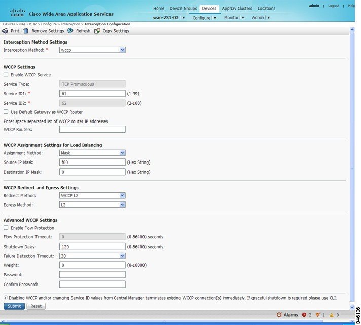
ステップ 2 [Configure] > [Interception] > [Interception Configuration] を選択します。[Interception Configuration] ウィンドウが表示されます。(図 5-3 を参照)。
(注![]() ) バージョン 5.0 よりも前の WAAS を使用しているデバイスを設定する場合は、[Configure] > [Interception] > [WCCP] > [Settings] を選択して、WCCP 設定を行います。設定ウィンドウの見た目は異なりますが、同様の設定があります。
) バージョン 5.0 よりも前の WAAS を使用しているデバイスを設定する場合は、[Configure] > [Interception] > [WCCP] > [Settings] を選択して、WCCP 設定を行います。設定ウィンドウの見た目は異なりますが、同様の設定があります。
図 5-3 WAE の [Interception Configuration] ウィンドウ
- 現在の設定を保持し、ウィンドウを閉じるには、[Reset] をクリックします。
- 現在の設定を削除するには、[Remove Settings] タスクバー アイコンをクリックします。
- 現在の設定を変更するには、この手順の残りの説明に従って現在の設定を変更します。
- ネットワークの他の WAE に設定をコピーするには、[Copy Settings] タスクバー アイコンをクリックします。[Copy Interception Settings] ウィンドウが開きます。このウィンドウで、代行受信設定をコピーできる他の WAE を選択できます。すべての設定をコピーするか、またはルータ リストを除外し、WCCP サービスを有効にできます。[OK] をクリックして、選択した WAE デバイスに設定をコピーします。
デフォルトで、WAE 上の WCCP は無効になっています。ただし、WAAS ネットワークでの WCCP の初期設定の一環として、WAE(ブランチ オフィスの WAE とデータセンターの WAE)とこれらの要求を透過的に WAE へリダイレクトするデータセンターとブランチ オフィスのルータで、WCCP バージョン 2 が有効になっている必要があります。WAAS ネットワークで基本的な WCCP 設定を実行する手順については、『 Cisco Wide Area Application Services Quick Configuration Guide 』を参照してください。
ステップ 4 [Interception Method] ドロップダウン リストから、[wccp] を選択して WCCP 代行受信方式を有効にします。この設定を [None] 以外のいずれかの設定から変更する場合は、[Submit] ボタンをクリックして、WCCP を設定するための適切なフィールドでウィンドウを更新してください。(バージョン 5.0 よりも前の WAAS を使用しているデバイスの場合、[Interception Method] ドロップダウン リストは表示されません)。
ステップ 5 [Enable WCCP] チェックボックスを選択して、選択したデバイスの WCCP バージョン 2 を有効にします。または、チェックボックスの選択を解除して、選択したデバイスの WCCP を無効にします。
(注![]() ) WCCP 環境で使用しているルータで、WCCP バージョン 2 をサポートするバージョンの Cisco IOS ソフトウェアが稼働していることを確認します。
) WCCP 環境で使用しているルータで、WCCP バージョン 2 をサポートするバージョンの Cisco IOS ソフトウェアが稼働していることを確認します。
(注![]() ) Central Manager を使用して WAAS デバイス上での WCCP を無効にした場合、Central Manager は wccp shutdown max-wait グローバル コンフィギュレーション コマンドによる設定を無視して WCCP をただちにシャットダウンし、すべての既存の接続を終了します。WCCP 接続を正常にシャットダウンする場合は、WAAS デバイス上で no enable WCCP コンフィギュレーション コマンドを使用します。
) Central Manager を使用して WAAS デバイス上での WCCP を無効にした場合、Central Manager は wccp shutdown max-wait グローバル コンフィギュレーション コマンドによる設定を無視して WCCP をただちにシャットダウンし、すべての既存の接続を終了します。WCCP 接続を正常にシャットダウンする場合は、WAAS デバイス上で no enable WCCP コンフィギュレーション コマンドを使用します。
ステップ 6 [Service ID1] フィールドで、WCCP サービス ペアの最初のサービス ID を指定します。送信後に、[Service ID2] フィールドには、[Service ID1] よりも 1 つ大きいペアの 2 番目のサービス ID が表示されます。バージョン 4.4.1 以降を使用する WAE では、デフォルトの 61/62 から異なる数字のペアに WCCP サービス ID を変更できます。異なるファーム内の WAE は別のサービス ID を使用することがあるため、これによって、ルータは複数の WCCP ファームをサポートできます。(バージョン 4.4 よりも前の WAAS を使用しているデバイスの場合は、[Service ID] フィールドが表示されず、サービス ID は 61/21 に固定されます)。
ルータ サービスの優先順位は、サービス ID の数値とは逆になります。デフォルト サービス ID 61/62 のサービス優先順位は 34 です。より小さいサービス ID を指定した場合、サービス優先順位は 34 よりも高くなります。より大きいサービス ID を指定した場合、サービス優先順位は 34 よりも低くなります。
ステップ 7 [Use Default Gateway as WCCP Router] チェックボックスを選択して、WCCP TCP 無差別モード サービスに関連付けるルータとして、WAE デバイスのデフォルト ゲートウェイを使用します。または、このボックスの選択を解除し、ルータの IP アドレスで 1 台以上のルータを指定します(複数の場合はスペースで区切る)。Central Manager によりルータ リスト番号が割り当てられます。この番号は、ページの送信後にルータ リスト フィールドの横に表示されます。WAAS ネットワークの初期設定の一環として、『 Cisco Wide Area Application Services Quick Configuration Guide 』の説明に従って、設定ユーティリティを使用して WCCP ルータ リストがすでに作成されている場合があります。WCCP ルータ リストの詳細については、WAE 用の WCCP ルータ リストの設定および表示を参照してください。
(注![]() ) [Use Default Gateway as WCCP Router] チェックボックスの選択/選択解除、ルータ リストの変更、または WCCP ページの送信を行うと、WCCP サービスに割り当てられていない他のすべての既存のルータ リスト(設定ユーティリティまたは CLI を使用して設定したルータ リストを含む)が削除されます。
) [Use Default Gateway as WCCP Router] チェックボックスの選択/選択解除、ルータ リストの変更、または WCCP ページの送信を行うと、WCCP サービスに割り当てられていない他のすべての既存のルータ リスト(設定ユーティリティまたは CLI を使用して設定したルータ リストを含む)が削除されます。
ステップ 8 (任意)設定した割り当て方式だけを使用するように WCCP に強制するには、[Only Use Selected Assignment Method] チェックボックスを選択します。ブランチ オフィスの WAE サービス グループ内の WCCP サービスごとにどちらか一方のロード バランシング方式(ハッシュまたはマスキング)を指定できます。(このチェックボックスは、4.4 よりも前のバージョンの WAAS を使用しているデバイスでのみ表示されます)。
(注![]() ) [Only Use Selected Assignment Method] チェックボックスを選択した場合は、WAE で設定した割り当て方式がルータでサポートされている場合に限り、WAE は WCCP ファームに参加します。[Only Use Selected Assignment Method] チェックボックスの選択を解除した場合は、WAE がルータとは別に設定されている場合でも、WAE ではルータがサポートする割り当て方式が使用されます。
) [Only Use Selected Assignment Method] チェックボックスを選択した場合は、WAE で設定した割り当て方式がルータでサポートされている場合に限り、WAE は WCCP ファームに参加します。[Only Use Selected Assignment Method] チェックボックスの選択を解除した場合は、WAE がルータとは別に設定されている場合でも、WAE ではルータがサポートする割り当て方式が使用されます。
ステップ 9 (任意)[Assignment Method] ドロップダウン リストから、使用する WAE ロード バランシング割り当て方式の種類を選択します。
詳細については、ロード バランシングと WAE に関する情報を参照してください。
ステップ 10 (任意)送信元 IP アドレスの WCCP サービス ID1 にロード バランシング ハッシュを定義するには、[Hash on Source IP] チェックボックスを選択します。このチェックボックスは、ハッシュ割り当て方式が使用されている場合だけ表示されます。
ステップ 11 (任意)宛先 IP アドレスの WCCP サービス ID1 にロード バランシング ハッシュを定義するには、[Hash on Destination IP] チェックボックスを選択します。このチェックボックスは、ハッシュ割り当て方式が使用されている場合だけ表示されます。
ステップ 12 (任意)カスタム サービス マスクを使用するには、[WCCP Assignment Settings for Load Balancing] 領域で異なるマスク値を入力し、デフォルトのマスク設定を上書きします。これらの設定を変更しない場合は、デフォルトが使用されます。次のようにカスタム マスクを定義します。
(注![]() ) バージョン 4.1.x よりも前の WAAS を実行する WAE にデフォルト マスクを適用した場合、マスクは、バージョン 4.1.x よりも前の WAAS で設定されたデフォルト マスク(0x1741)とは異なります。
) バージョン 4.1.x よりも前の WAAS を実行する WAE にデフォルト マスクを適用した場合、マスクは、バージョン 4.1.x よりも前の WAAS で設定されたデフォルト マスク(0x1741)とは異なります。
設定されたマスクがファーム内の 1 つまたは複数のルータによってアドバタイズされたものと同じではないことを WAE が検出した場合、このマスクがファームへ加わることは許可されず、「 Configured mask mismatch for WCCP 」というメジャー アラームが出力されます。このアラームは、WAE がすでに他の WAE が設定されているファームに加わろうとし、これらの他の WAE が別のマスクを使用して設定されている場合に、出力されることがあります。ルータは、他の WAE が同じマスクをアドバタイズするのでない限り、これらの WAE がファームへ加わることを許可しません。このアラームを解消するには、ファーム内のすべての WAE が同じマスクを使用して設定されていることを確認します。このアラームは、WAE で設定されているマスクが、ファーム内のすべてのルータのマスクに一致した場合にクリアされます。
ステップ 13 [Redirect Method] ドロップダウン リストから、使用するパケット リダイレクション(転送)方式の種類を選択します。
- [WCCP GRE](バージョン 5.0 よりも前の WAAS を使用しているデバイスのデフォルト):レイヤ 3 GRE パケット リダイレクションを使用します。
- [WCCP L2](WAAS バージョン 5.0 以降を使用しているデバイスのデフォルト):WAE がデバイスとレイヤ 2 接続を確立していて、デバイスがレイヤ 2 リダイレクション用に設定されている場合に、WAE が WCCP バージョン 2 対応スイッチまたはルータから透過的にリダイレクトされたトラフィックを受信できるようにします。詳細については、パケット転送方式に関する情報を参照してください。
(注![]() ) IP アンナンバードがホスト ルータの VirtualPortGroup インターフェイスに設定されている場合は、ISR-WAAS デバイスで WCCP L2 リダイレクションを使用しないでください。デバイスは WCCP ファームと組み合わせることはできません。missing_assignment アラームが発生します。
) IP アンナンバードがホスト ルータの VirtualPortGroup インターフェイスに設定されている場合は、ISR-WAAS デバイスで WCCP L2 リダイレクションを使用しないでください。デバイスは WCCP ファームと組み合わせることはできません。missing_assignment アラームが発生します。
ステップ 14 [Return Method] ドロップダウン リストから、最適化されていない(バイパスされた)パケットをルータに返信するために使用する方式の種類を選択します。
[Return Method] ドロップダウン リストは、バージョン 5.0 よりも前の WAAS を使用しているデバイスでのみ表示されます。WAAS バージョン 5.1 の場合、リターン方式はリダイレクト方式と同じものに設定されます。WAAS バージョン 5.2 以降の場合、リターン方式がリダイレクト方式と同じルータと自動的にネゴシエートします(ルータがサポートしている場合)。ルータがリダイレクション方式と一致するリターン方式をサポートしていない場合、リターン方式はルータによってサポートされるリターン方式に設定されます。たとえば、リダイレクション方式が WCCP L2 に設定されているが、ルータが GRE リターン方式のみをサポートする場合、リターン方式は WCCP GRE に設定されます。
ステップ 15 (任意)[Egress Method] ドロップダウン リストから、最適化されたパケットをルータまたはスイッチに返信するために使用する方式を選択します。
バージョン 5.0 よりも前の WAAS を使用しているデバイスの場合、選択肢は [IP Forwarding](デフォルト)、[WCCP Negotiated Return]、または [Generic GRE] になります。出力方式の選択の詳細については、WCCP 代行受信接続の出力方式の設定を参照してください。
ステップ 16 (任意)次のように、[Advanced WCCP Settings] 領域で現在の詳細設定を変更します。
- デバイスが起動したときやデバイスに新しいトラフィックが再割り当てされる際に、TCP フローを維持し、デバイスに過剰な負荷がかかるのを防止するには、[Enable Flow Protection] チェックボックスをオンにします。 フローの保護はデフォルトで無効になります。
- [Flow Protection Timeout] フィールドで、フローの保護が有効になる時間(秒)を指定します。デフォルトは 0 で、これはタイムアウトなしで有効な状態が維持されることを意味します。(バージョン 5.0 よりも前の WAAS を使用しているデバイスの場合、[Flow Protection Timeout] フィールドは表示されません)。
(注![]() ) [Enable Flow Protection] チェック ボックスと [Flow Protection Timeout] フィールドは WAAS v6.0.1 では有効になっていません。
) [Enable Flow Protection] チェック ボックスと [Flow Protection Timeout] フィールドは WAAS v6.0.1 では有効になっていません。
WAE は、すべての接続が処理されるか、(この [Shutdown Delay] フィールドで指定した)WCCP 用の最大待ち時間が経過するまで再起動しません。
障害検出タイムアウト値は、ルータとネゴシエートされ、ルータに可変タイムアウト機能がある場合にだけ有効になります。ルータの固定タイムアウトが 30 秒で、WAE で、デフォルトの 30 秒以外の障害検出値を設定した場合、WAE は、ファームに参加できず、アラームが生成されます(「 Router unusable 」とその原因「 Timer interval mismatch with router 」)。
- [Weight] フィールドで、ロード バランシングに使用される重み値を指定します。重み値の範囲は、0 ~ 10000 です。サービス グループ内の WAE の全重み値の合計が 100 以下である場合、重み値はそのまま、ロード バランシングのためにデバイスにリダイレクトされる合計負荷に対する比率となります。たとえば、重み値 10 の WAE は、すべての重み値の合計が 50 のサービス グループで合計負荷の 10% を受け取ります。そのようなサービス グループの WAE に障害が発生した場合、別の WAE は障害前と同じ負荷パーセントを受け取り、障害のある WAE に割り当てられた負荷は受け取りません。
サービス グループで WAE のすべての重み値の合計が 101 ~ 10000 の間である場合、重み値は、サービス グループでのアクティブな WAE すべての合計の重み付けの割合として扱われます。たとえば、重み値 200 の WAE は、すべての重み値の合計が 800 のサービス グループで合計負荷の 25% を受け取ります。そのようなサービス グループの WAE に障害が発生した場合、別の WAE が障害のある WAE に割り当てられていた負荷を受け取ります。フェールオーバーの処理は、重みの合計が 100 以下の場合と異なります。
デフォルトで、重みは割り当てられず、トラフィックの負荷はサービス グループ内の WAE の間で均等に分散されます。
(注![]() ) CLI を使用してルータ上のサービス グループのパスワードを指定する方法については、ルータ上のサービス グループ パスワードの設定を参照してください。
) CLI を使用してルータ上のサービス グループのパスワードを指定する方法については、ルータ上のサービス グループ パスワードの設定を参照してください。
ステップ 17 [Submit] をクリックして、設定を保存します。
CLI から WCCP 設定を行うには、最初に interception-method グローバル コンフィギュレーション コマンドを使用して代行受信方式を設定する必要があります。次に、 wccp router-list 、 wccp shutdown 、および wccp tcp-promiscuous のグローバル コンフィギュレーション コマンドを使用できます。
WAE 上の WCCP バージョン 2 の正常なシャットダウンの詳細については、WCCP の正常なシャットダウンのための WAE の設定を参照してください。
ANC 上での WCCP の設定および WCCP 設定の表示
この項では、AppNav コントローラ(ANC)として設定された WAAS デバイス上で、WCCP の設定または WCCP 設定の表示を行う方法について説明します。通常は WCCP の設定を含む Central Manager の AppNav クラスタ ウィンドウを使用して、ANC およびその構成を設定します。そのため、このセクションで説明されているように、AppNav クラスタ コンテキスト外で WCCP の設定をする必要はありません。
アプリケーション アクセラレータとして設定された WAE 上で WCCP の設定または WCCP 設定の表示を行う場合は、WAE 上での WCCP の設定および WCCP 設定の表示を参照してください。AppNav コントローラの WAAS ノードとして動作する WAE 上で代行受信設定を行うには、AppNav 代行受信の設定を参照してください。
デバイス グループの設定は、WAAS バージョン 5.0 では行えません。ただし、設定ウィンドウの [Copy Settings] タスクバー アイコンを使用して、ネットワークの他のデバイスに設定をコピーできます。一貫性を確保するため、同じ WCCP サービス ファームのすべてのデバイスに同じ WCCP 設定をコピーすることを推奨します。
ANC 用の WCCP の設定を変更するには、次の手順に従ってください。
ステップ 1 WAAS Central Manager メニューから、[Devices] > [ device-name ] を選択します。
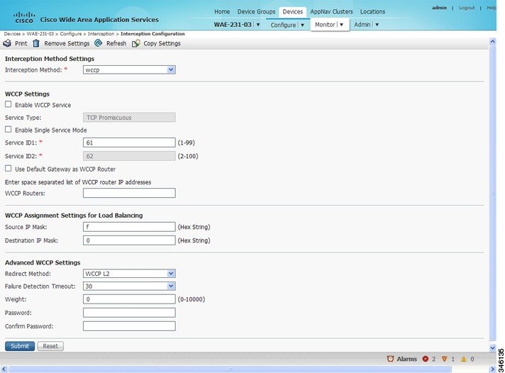
ステップ 2 [Configure] > [Interception] > [Interception Configuration] を選択します。[Interception Configuration] ウィンドウが表示されます。(図 5-4 を参照)。
図 5-4 ANC の [Interception Configuration] ウィンドウ
- 現在の設定を保持し、ウィンドウを閉じるには、[Reset] をクリックします。
- 現在の設定を削除するには、[Remove Settings] タスクバー アイコンをクリックします。
- 現在の設定を変更するには、この手順の残りの説明に従って現在の設定を変更します。
- ネットワークの他の WAE に設定をコピーするには、[Copy Settings] タスクバー アイコンをクリックします。[Copy Interception Settings] ウィンドウが開きます。このウィンドウで、代行受信設定をコピーできる他の WAE を選択できます。すべての設定をコピーするか、またはルータ リストを除外し、WCCP サービスを有効にできます。[OK] をクリックして、選択した WAE デバイスに設定をコピーします。
デフォルトで、WAE 上の WCCP は無効になっています。ただし、WAAS ネットワークでの WCCP の初期設定の一環として、WAE(ブランチ オフィスの WAE とデータセンターの WAE)とこれらの要求を透過的に WAE へリダイレクトするデータセンターとブランチ オフィスのルータで、WCCP バージョン 2 が有効になっている必要があります。WAAS ネットワークで基本的な WCCP 設定を実行する手順については、『 Cisco Wide Area Application Services Quick Configuration Guide 』を参照してください。
ステップ 4 [Interception Method] ドロップダウン リストから、[wccp] を選択して WCCP 代行受信方式を有効にします。この設定を [None] 以外のいずれかの設定から変更する場合は、[Submit] ボタンをクリックして、WCCP を設定するための適切なフィールドでウィンドウを更新してください。
ステップ 5 [Enable WCCP Service] チェックボックスを選択して、選択したデバイスの WCCP バージョン 2 を有効にします。または、チェックボックスの選択を解除して、選択したデバイスの WCCP を無効にします。
(注![]() ) WCCP 環境で使用しているルータで、WCCP バージョン 2 をサポートするバージョンの Cisco IOS ソフトウェアが稼働していることを確認します。
) WCCP 環境で使用しているルータで、WCCP バージョン 2 をサポートするバージョンの Cisco IOS ソフトウェアが稼働していることを確認します。
(注![]() ) Central Manager を使用して WAAS デバイス上での WCCP を無効にした場合、Central Manager は wccp shutdown max-wait グローバル コンフィギュレーション コマンドによる設定を無視して WCCP をただちにシャットダウンし、すべての既存の接続を終了します。WCCP 接続を正常にシャットダウンする場合は、WAAS デバイス上で no enable WCCP コンフィギュレーション コマンドを使用します。
) Central Manager を使用して WAAS デバイス上での WCCP を無効にした場合、Central Manager は wccp shutdown max-wait グローバル コンフィギュレーション コマンドによる設定を無視して WCCP をただちにシャットダウンし、すべての既存の接続を終了します。WCCP 接続を正常にシャットダウンする場合は、WAAS デバイス上で no enable WCCP コンフィギュレーション コマンドを使用します。
ステップ 6 (任意)[Enable Single Service Mode] チェックボックスを選択して、シングル サービス モードを有効にできます。シングル サービス モードでは、着信トラフィックと発信トラフィックに対して同じサービス ID を使用することにより設定が簡素化されます。これが可能になるのは AppNav 導入のみで、その理由は非対称トラフィック フローを処理できるからです。
ステップ 7 [Service ID1] フィールドで、WCCP サービスのサービス ID を指定します。
[Enable Single Service Mode] チェックボックスの選択が解除されている場合は、WCCP サービス ID のペアが必要になり、[Service ID2] フィールドには、[Service ID1] よりも 1 つ大きいペアの 2 番目のサービス ID が表示されます。デフォルトのサービス ID は 61 と 62 です。デフォルトの 61/62 から異なる数字のペアに WCCP サービス ID を変更できます。異なるファーム内の ANC は別のサービス ID を使用することがあるため、これによって、ルータは複数の WCCP ファームをサポートできます。
ルータ サービスの優先順位は、サービス ID の数値とは逆になります。デフォルト サービス ID 61/62 のサービス優先順位は 34 です。より小さいサービス ID を指定した場合、サービス優先順位は 34 よりも高くなります。より大きいサービス ID を指定した場合、サービス優先順位は 34 よりも低くなります。
ステップ 8 [Use Default Gateway as WCCP Router] チェックボックスを選択して、WCCP TCP 無差別モード サービスに関連付けるルータとして、WAE デバイスのデフォルト ゲートウェイを使用します。または、このチェック ボックスの選択を解除し、ルータの IP アドレスで 1 台以上のルータを指定します(複数の場合はスペースで区切る)。Central Manager によりルータ リスト番号が割り当てられます。この番号は、ページの送信後にルータ リスト フィールドの横に表示されます。WAAS ネットワークの初期設定の一環として、『 Cisco Wide Area Application Services Quick Configuration Guide 』の説明に従って、設定ユーティリティを使用して WCCP ルータ リストがすでに作成されている場合があります。WCCP ルータ リストの詳細については、WAE 用の WCCP ルータ リストの設定および表示を参照してください。
(注![]() ) [Use Default Gateway as WCCP Router] チェックボックスの選択/選択解除、ルータ リストの変更、または WCCP ページの送信を行うと、WCCP サービスに割り当てられていない他のすべての既存のルータ リスト(設定ユーティリティまたは CLI を使用して設定したルータ リストを含む)が削除されます。
) [Use Default Gateway as WCCP Router] チェックボックスの選択/選択解除、ルータ リストの変更、または WCCP ページの送信を行うと、WCCP サービスに割り当てられていない他のすべての既存のルータ リスト(設定ユーティリティまたは CLI を使用して設定したルータ リストを含む)が削除されます。
ステップ 9 (任意)カスタム サービス マスクを使用するには、[WCCP Assignment Settings for Load Balancing] 領域で異なるマスク値を入力し、デフォルトのマスク設定を上書きします。これらの設定を変更しない場合は、デフォルトが使用されます。次のようにカスタム マスクを定義します。
詳細については、ロード バランシングと WAE に関する情報を参照してください。
設定されたマスクがファーム内の 1 つまたは複数のルータによってアドバタイズされたものと同じではないことを WAE が検出した場合、このマスクがファームへ加わることは許可されず、「 Configured mask mismatch for WCCP 」というメジャー アラームが出力されます。このアラームは、WAE がすでに他の WAE が設定されているファームに加わろうとし、これらの他の WAE が別のマスクを使用して設定されている場合に、出力されることがあります。ルータは、他の WAE が同じマスクをアドバタイズするのでない限り、これらの WAE がファームへ加わることを許可しません。このアラームを解消するには、ファーム内のすべての WAE が同じマスクを使用して設定されていることを確認します。このアラームは、WAE で設定されているマスクが、ファーム内のすべてのルータのマスクに一致した場合にクリアされます。
ステップ 10 (任意)次のように、[Advanced WCCP Settings] 領域で現在の詳細設定を変更します。
a.![]() [Redirect Method] ドロップダウン リストから、使用するパケット リダイレクション(転送)方式の種類を選択します。
[Redirect Method] ドロップダウン リストから、使用するパケット リダイレクション(転送)方式の種類を選択します。
–![]() [WCCP GRE]:レイヤ 3 GRE パケット リダイレクションを使用します。
[WCCP GRE]:レイヤ 3 GRE パケット リダイレクションを使用します。
–![]() [WCCP L2](デフォルト):WAE がデバイスとレイヤ 2 接続を確立していて、デバイスがレイヤ 2 リダイレクション用に設定されている場合に、WAE が WCCP バージョン 2 対応スイッチまたはルータから透過的にリダイレクトされたトラフィックを受信できるようにします。詳細については、パケット転送方式に関する情報を参照してください。
[WCCP L2](デフォルト):WAE がデバイスとレイヤ 2 接続を確立していて、デバイスがレイヤ 2 リダイレクション用に設定されている場合に、WAE が WCCP バージョン 2 対応スイッチまたはルータから透過的にリダイレクトされたトラフィックを受信できるようにします。詳細については、パケット転送方式に関する情報を参照してください。
リターン方式はリダイレクト方式と同じものに設定されます。リターン方式は、WCCP GRE リダイレクト方式が選択されている場合は汎用 GRE になり、WCCP L2 リダイレクト方式が選択されている場合は WCCP L2 リターンになります。
b.![]() [Failure Detection Timeout] ドロップダウン リストで、障害検出タイムアウト値を選択します(3 秒、6 秒、9 秒、15 秒、または 30 秒)。デフォルトは 30 秒です。これは、4.4.1 よりも前の WAAS バージョンでサポートされている唯一の値です。この障害検出値によって、ルータが WAE 障害を検出するまでにかかる時間が決定されます。
[Failure Detection Timeout] ドロップダウン リストで、障害検出タイムアウト値を選択します(3 秒、6 秒、9 秒、15 秒、または 30 秒)。デフォルトは 30 秒です。これは、4.4.1 よりも前の WAAS バージョンでサポートされている唯一の値です。この障害検出値によって、ルータが WAE 障害を検出するまでにかかる時間が決定されます。
障害検出タイムアウト値は、ルータとネゴシエートされ、ルータに可変タイムアウト機能がある場合にだけ有効になります。ルータの固定タイムアウトが 30 秒で、WAE で、デフォルトの 30 秒以外の障害検出値を設定した場合、WAE は、ファームに参加できず、アラームが生成されます(「 Router unusable 」とその原因「 Timer interval mismatch with router 」)。
c.![]() [Weight] フィールドで、ロード バランシングに使用される重み値を指定します。重み値の範囲は、0 ~ 10000 です。サービス グループ内の WAE の全重み値の合計が 100 以下である場合、重み値はそのまま、ロード バランシングのためにデバイスにリダイレクトされる合計負荷に対する比率となります。たとえば、重み値 10 の WAE は、すべての重み値の合計が 50 のサービス グループで合計負荷の 10% を受け取ります。そのようなサービス グループの WAE に障害が発生した場合、別の WAE は障害前と同じ負荷パーセントを受け取り、障害のある WAE に割り当てられた負荷は受け取りません。
[Weight] フィールドで、ロード バランシングに使用される重み値を指定します。重み値の範囲は、0 ~ 10000 です。サービス グループ内の WAE の全重み値の合計が 100 以下である場合、重み値はそのまま、ロード バランシングのためにデバイスにリダイレクトされる合計負荷に対する比率となります。たとえば、重み値 10 の WAE は、すべての重み値の合計が 50 のサービス グループで合計負荷の 10% を受け取ります。そのようなサービス グループの WAE に障害が発生した場合、別の WAE は障害前と同じ負荷パーセントを受け取り、障害のある WAE に割り当てられた負荷は受け取りません。
サービス グループで WAE のすべての重み値の合計が 101 ~ 10000 の間である場合、重み値は、サービス グループでのアクティブな WAE すべての合計の重み付けの割合として扱われます。たとえば、重み値 200 の WAE は、すべての重み値の合計が 800 のサービス グループで合計負荷の 25% を受け取ります。そのようなサービス グループの WAE に障害が発生した場合、別の WAE が障害のある WAE に割り当てられていた負荷を受け取ります。フェールオーバーの処理は、重みの合計が 100 以下の場合と異なります。
デフォルトで、重みは割り当てられず、トラフィックの負荷はサービス グループ内の WAE の間で均等に分散されます。
d.![]() [Password] フィールドで、クラスタ内の WAE と指定したサービス用のルータ間の安全なトラフィックに使用するパスワードを指定します。クラスタ内の他のすべての WAE とルータを同じパスワードで有効にします。パスワードの長さは、8 文字以内です。スペース、左一重引用符(`)、二重引用符(")、パイプ(|)、または疑問符(?)の文字は使用しないでください。[Confirm Password] フィールドに、パスワードを再入力します。
[Password] フィールドで、クラスタ内の WAE と指定したサービス用のルータ間の安全なトラフィックに使用するパスワードを指定します。クラスタ内の他のすべての WAE とルータを同じパスワードで有効にします。パスワードの長さは、8 文字以内です。スペース、左一重引用符(`)、二重引用符(")、パイプ(|)、または疑問符(?)の文字は使用しないでください。[Confirm Password] フィールドに、パスワードを再入力します。
(注![]() ) CLI を使用してルータ上のサービス グループのパスワードを指定する方法については、ルータ上のサービス グループ パスワードの設定を参照してください。
) CLI を使用してルータ上のサービス グループのパスワードを指定する方法については、ルータ上のサービス グループ パスワードの設定を参照してください。
ステップ 11 [Submit] をクリックして、設定を保存します。
CLI から WCCP 設定を行うには、最初に interception-method グローバル コンフィギュレーション コマンドを使用して代行受信方式を設定する必要があります。次に、 wccp router-list および wccp tcp-promiscuous のグローバル コンフィギュレーション コマンドを使用できます。
WAE 用の WCCP ルータ リストの設定および表示
WCCP 設定を使用して、Central Manager から 1 つのルータ リストを設定および表示できます(WAE 上での WCCP の設定および WCCP 設定の表示を参照)。Central Manager では、WCCP サービスに割り当てられた単一のルータ リストのみがサポートされるため、Central Manager を使用してルータ リストを設定した場合、WCCP 設定ページの [Use Default Gateway] チェックボックスを選択/選択解除した場合、または WCCP 設定ページを送信した場合は、CLI を使用して設定された既存のルータ リストが削除されます。CLI からルータ リストを設定するには、 wccp router-list グローバル コンフィギュレーション コマンドを使用できます。
(注![]() ) WCCP グローバル コンフィギュレーション コマンドを使用する前に、WCCP を有効にする必要があります。
) WCCP グローバル コンフィギュレーション コマンドを使用する前に、WCCP を有効にする必要があります。
ルータ リストを削除するには、 no wccp router-list グローバル コンフィギュレーション コマンドを使用します。
wccp router-list コマンドにより設定された未割り当てのルータ リストを表示するには、 show running-config wccp EXEC コマンドを使用します。
WCCP の正常なシャットダウンのための WAE の設定
TCP 接続の切断を防止するために、WAE は、WAE で WCCP バージョン 2 を無効にしたり、CLI から WAE をリロードしたりした後で、WCCP の正常なシャットダウンを実行します。デバイス上で CLI を使用して no enable WCCP コンフィギュレーション コマンドを入力することにより、この作業をローカルで実行できます。
また、WAAS Central Manager を使用すると、WAE で WCCP バージョン 2 を無効にできますが、その場合は WCCP 接続の正常なシャットダウンは実行されません。選択したデバイスの WCCP をただちに無効にするには、[WAAS Central Manager Interception Configuration] ウィンドウの [Enable WCCP] チェックボックスの選択を解除します。(図 5-3 を参照)。
(注![]() ) Central Manager を使用して WAAS デバイス上での WCCP を無効にした場合、Central Manager は wccp shutdown max-wait グローバル コンフィギュレーション コマンドによる設定を無視して WCCP をただちにシャットダウンし、すべての既存の接続を終了します。WCCP 接続を正常にシャットダウンする場合は、WAAS デバイス上で no enable WCCP コンフィギュレーション コマンドを使用します。
) Central Manager を使用して WAAS デバイス上での WCCP を無効にした場合、Central Manager は wccp shutdown max-wait グローバル コンフィギュレーション コマンドによる設定を無視して WCCP をただちにシャットダウンし、すべての既存の接続を終了します。WCCP 接続を正常にシャットダウンする場合は、WAAS デバイス上で no enable WCCP コンフィギュレーション コマンドを使用します。
正常なシャットダウン中には、次のいずれかの状況になるまで WAE はリブートしません。
WCCP の正常なシャットダウンの間、WAE は継続して処理中のフローにサービスを提供しますが、新しいフローのバイパスを開始します。フローの数がゼロになると、リード WAE は、そのバケットを他の WAE に再度割り当ててグループから脱退します。WCCP を正常にシャットダウンすることなく WAE が機能停止またはリブートした場合は、TCP 接続が切断される可能性が残ります。
WAE の特定のポートで個々の WCCP サービスをシャットダウンできません。WAE の WCCP をシャットダウンする必要があります。WAE 上の WCCP がシャットダウンされると、WAE は自分の WCCP 構成の設定値を保存します。
WAE 用の固定バイパス リストの設定
(注![]() ) 固定バイパス リストは、バージョン 5.0 よりも前の WAAS を使用しているデバイス(ただし、デバイス グループは不可)においてのみサポートされ、これらのデバイスでは推奨されません。代わりに、代行受信 ACL が推奨されます。
) 固定バイパス リストは、バージョン 5.0 よりも前の WAAS を使用しているデバイス(ただし、デバイス グループは不可)においてのみサポートされ、これらのデバイスでは推奨されません。代わりに、代行受信 ACL が推奨されます。
固定バイパスを使用すると、設定可能な 1 組のクライアントとサーバ間のトラフィックのフローを WAE によってバイパス処理することができます。ブランチ オフィスの WAE に固定バイパス項目を設定すると、ルータの設定を変更することなく、トラフィックの代行受信を制御できます。ルータで、最初にトラフィックをブランチ オフィスの WAE へリダイレクトせず、トラフィックをバイパスするように、IP アクセス リストを個別に設定できます。通常、WCCP 受け入れリストは、加速されるサーバのグループを定義します(暗黙的に、加速されないサーバが定義されることとなります)。特定のクライアントから特定のサーバ(または特定のクライアントからすべてのサーバ)への接続を WAAS が加速しないようにするには、固定バイパスを使用できます。
(注![]() ) WAE で固定バイパス リストまたは代行受信 ACL を使用するのではなく、可能な場合は WCCP 対応ルータの ACL を使用することを推奨します。この方法が、トラフィック代行受信を制御するのに最も効率的です。固定バイパス リストまたは代行受信 ACL の使用を決定した場合、代行受信 ACL を使用することを推奨します。これは、代行受信 ACL の方が柔軟性が高く、パススルー接続についてより優れた統計情報が得られるためです。ルータ上で ACL を設定する方法については、ルータ上の IP アクセス リストの設定を参照してください。WAE の代行受信 ACL を設定する方法の詳細については、代行受信アクセス コントロール リストの設定を参照してください。
) WAE で固定バイパス リストまたは代行受信 ACL を使用するのではなく、可能な場合は WCCP 対応ルータの ACL を使用することを推奨します。この方法が、トラフィック代行受信を制御するのに最も効率的です。固定バイパス リストまたは代行受信 ACL の使用を決定した場合、代行受信 ACL を使用することを推奨します。これは、代行受信 ACL の方が柔軟性が高く、パススルー接続についてより優れた統計情報が得られるためです。ルータ上で ACL を設定する方法については、ルータ上の IP アクセス リストの設定を参照してください。WAE の代行受信 ACL を設定する方法の詳細については、代行受信アクセス コントロール リストの設定を参照してください。
バージョン 4.x の WAE 用の固定バイパス リストを設定するには、次の手順に従ってください。
ステップ 1 WAAS Central Manager メニューから、[Devices] > [ device-name ] を選択します。
ステップ 2 [Configure] > [Interception] > [Bypass Lists] を選択します。
ステップ 3 タスクバーで、[Create New WCCP/Inline Bypass List] アイコンをクリックします。[Creating new WCCP/Inline Bypass List] ウィンドウが表示されます
ステップ 4 [Client Address] フィールドに、クライアントの IP アドレスを入力します。
ステップ 5 [Server Address] フィールドに、サーバの IP アドレスを入力します。
ステップ 6 [Submit] をクリックして、設定を保存します。
CLI から固定バイパス リストを設定するには、 bypass static グローバル コンフィギュレーション コマンドを使用できます。
代行受信アクセス コントロール リストの設定
代行受信 ACL を設定することにより、すべてのインターフェイスでどの着信トラフィックが ANC または WAE デバイスにより代行受信されるかを制御できます(ANC 上では、代行受信 ACL は AppNav コントローラ代行受信 ACL と呼ばれます)。ACL により許可されたパケットは、デバイスによって代行受信され、ACL によって拒否されたパケットは処理されずに通過します。
WAAS デバイス上で代行受信 ACL を設定すると、ルータの設定を変更することなく、トラフィックの代行受信を制御できます。ルータで、最初にトラフィックを WAAS デバイスへリダイレクトせず、トラフィックをバイパスするように、IP ACL を個別に設定できます。通常、WCCP 受け入れリストは、加速されるサーバのグループを定義します(暗黙的に、加速されないサーバが定義されることとなります)。代行受信 ACL を使用することで、ルータ設定の変更を望まないパイロット導入時などに、対象外のトラフィックを容易にバイパスできます。更に、フェーズにおけるさまざまな種類のトラフィックを許可して促進することで、パイロットから実稼働導入への移行を容易に行えます。
代行受信 ACL は、WCCP とインライン代行受信の両方で使用できます。
代行受信 ACL をインターフェイス ACL および WCCP ACL を併用した場合、最初にインターフェイス ACL が、2 番めに WCCP ACL が、最後に代行受信 ACL が適用されます。WAE で定義されているアプリケーション ポリシーは、すべての ACL がトラフィックをフィルタした後に適用されます。
WAAS ノードとしても動作している ANC では、AppNav コントローラの代行受信 ACL により ANC による代行受信の対象を制御するだけではなく、代行受信 ACL により、最適化を行っているエンジンにより受け入れられる対象を制御できます。フローは AppNav コントローラの代行受信 ACL により許可された後に、WAAS ノードの代行受信 ACL により拒否される場合があります。
(注![]() ) 代行受信 ACL は、固定バイパス リストとは排他的な機能です。両方のタイプのリストを同時に使用することはできません。固定バイパス リストではなく代行受信 ACL を使用することを推奨します。固定バイパス リストは、バージョン 5.0 よりも前の WAAS を使用しているデバイスにおいてのみサポートされます。
) 代行受信 ACL は、固定バイパス リストとは排他的な機能です。両方のタイプのリストを同時に使用することはできません。固定バイパス リストではなく代行受信 ACL を使用することを推奨します。固定バイパス リストは、バージョン 5.0 よりも前の WAAS を使用しているデバイスにおいてのみサポートされます。
代行受信 ACL を使用するには、まず ACL を定義し(Chapter 9, “Cisco WAAS デバイス用の IP アクセス コントロール リストの作成および管理”を参照)、次にその ACL をデバイスに適用します。代行受信 ACL は、個々のデバイスにのみ設定でき、デバイス グループには設定できません。
ANC または WAE デバイスの代行受信 ACL を設定するには、次の手順に従ってください。
ステップ 1 Chapter 9, “Cisco WAAS デバイス用の IP アクセス コントロール リストの作成および管理”の手順に従って、代行受信に使用する ACL を作成します。ただし、この ACL をインターフェイスには適用しないでください。
ステップ 2 WAAS Central Manager メニューから、[Devices] > [ device-name ] を選択します。
ステップ 3 [Configure] > [Interception] > [Interception Access List] を選択します。
ステップ 4 WAE の代行受信 ACL を設定するには、[Interception Access List] フィールドの横にある矢印をクリックして、定義した ACL のドロップダウン リストを表示し、WAE の代行受信に適用する ACL を選択します。または、ACL の名前をフィールドに直接入力して、このページを送信した後、ACL を作成することもできます。情報を入力すると、ACL が表示されたドロップダウン リストは、入力したテキストの先頭に一致するエントリだけを表示するようフィルタリングされます。
ACL を作成または編集するには、このフィールドの横にある [Go to IP ACL] リンクをクリックすると、IP ACL 設定用ウィンドウが表示されます([Configure] > [Network] > [TCP/IP Settings] > [IP ACL] )。
ステップ 5 ANC の代行受信 ACL を設定するには、AppNav コントローラの [Interception Access List] フィールドの横にある矢印をクリックして、定義した ACL のドロップダウン リストを表示し、ANC の代行受信に適用する ACL を選択します。または、ACL の名前をフィールドに直接入力して、このページを送信した後、ACL を作成することもできます。情報を入力すると、ACL が表示されたドロップダウン リストは、入力したテキストの先頭に一致するエントリだけを表示するようフィルタリングされます。このフィールドは、appnav-controller モードで設定したデバイス上でのみ表示されます。
ACL を作成または編集するには、[Go to IP ACL] リンクをクリックすると、IP ACL 設定用ウィンドウが表示されます([Configure] > [Network] > [TCP/IP Settings] > [IP ACL])。
ステップ 6 [Submit] をクリックして、設定を保存します。
(注![]() ) AppNav コントローラの代行受信 ACL では、tcp... established の拡張 ACL 条件はサポートされないため、これが発生した場合は無視されます。
) AppNav コントローラの代行受信 ACL では、tcp... established の拡張 ACL 条件はサポートされないため、これが発生した場合は無視されます。
CLI から代行受信 ACL を設定するには、 ip access-list および interception access-list グローバル コンフィギュレーション コマンドを使用します。AppNav コントローラの代理受信 ACL を設定するには、 interception appnav-controller access-list グローバル コンフィギュレーション コマンドを使用します。
接続が代行受信 ACL で通過されたかどうかを判別するには、 show statistics connection EXEC コマンドを使用します。代行受信 ACL によるフローのパススルーは、接続タイプ「PT Interception ACL」で識別されます。
また、 show statistics pass-through コマンドの「Interception ACL」カウンタにより、代行受信 ACL によるアクティブなパススルーと完了したパススルーの数がレポートされます。
WCCP 代行受信接続の出力方式の設定
出力方式に関する情報
Cisco WAAS ソフトウェアでは、次の出力方式による WCCP 代行受信接続をサポートします。
- IP 転送
- WCCP GRE 返信(リダイレクト方式が WCCP GRE の場合にのみ使用可能。バージョン 5.0 よりも前の WAAS デバイスでは、WCCP がネゴシエートする返信と呼ばれる)
- 汎用 GRE(リダイレクト方式が WCCP GRE の場合にのみ使用可能)
- レイヤ 2(リダイレクト方式が WCCP L2 の場合にのみ使用可能)
(注![]() ) ANC の出力方式は設定できません。使用される出力方式は、リダイレクト方式によって変わります。ANC では、WCCP GRE リダイレクト方式が選択されている場合は汎用 GRE が使用され、WCCP L2 リダイレクト方式が選択されている場合はレイヤ 2 が使用されます。
) ANC の出力方式は設定できません。使用される出力方式は、リダイレクト方式によって変わります。ANC では、WCCP GRE リダイレクト方式が選択されている場合は汎用 GRE が使用され、WCCP L2 リダイレクト方式が選択されている場合はレイヤ 2 が使用されます。
デフォルトの出力方式は L2 です。この出力方式では、最適化されたデータがレイヤ 2 接続によりルータに送信されます。この方式は、リダイレクト方式もまた WCCP L2 に設定されている場合にのみ使用でき、バージョン 5.0 よりも前の WAAS を使用しているデバイス上では使用できません。また、ルータがレイヤ 2 リダイレクトをサポートしている必要があります。WCCP GRE リダイレクト方式を設定する場合、または WCCP GRE と L2 間で切り替える場合は、デフォルトの出力方式が IP 転送に設定されます。
バージョン 5.0 よりも前の WAAS を使用しているデバイスの場合、デフォルトの出力方式は IP 転送になります。IP 転送出力方式では、WAE をクライアントおよびサーバとして同一の VLAN またはサブネットに配置することはできません。また、パケットが代行受信ルータに返信されるとは限りません。
WCCP GRE 返信および汎用 GRE 出力方式では、WAE をクライアントおよびサーバと同じ VLAN またはサブネットに配置することができます。発信パケットを GRE フレームにカプセル化することで、リダイレクションの繰り返しを防止します。Cisco IOS ソフトウェアを使用しているルータは、これらの GRE フレームをバイパス フレームとして処理し、WCCP リダイレクションを適用しません。WCCP GRE 返信方式では、WAAS はルータ ID アドレスを GRE フレームの送信先として使用します。汎用 GRE 方式では、WAAS は WAE ルータ リストで設定されたルータのアドレスを使用します。
この技術によって、冗長なルータとルータのロード バランシングのサポートが可能となり、WAAS はフレームを送信元ルータに返信するための最善の努力をします(ただし、これは保証されません)。
WAAS ネットワークに接続された複数のルータとともにこの機能を使用する場合は、たとえば、固定ルートを設定して、ルータ ID アドレスへの接続を確保します。ルータ ID は、最初のループバック インターフェイスまたは最もアクティブな物理インターフェイスのアドレスです。このアドレスは、 show wccp routers EXEC コマンドの出力で確認できます。
WAAS は、次の論理に基づいて WCCP GRE および汎用 GRE のルータを選択します。
- WAAS ソフトウェアが DRE(データ冗長性除去)を実行して TCP フローを圧縮すると、出力されるパケット数は減少します。最適化されたデータを送信する単一パケットが、複数のルータからリダイレクトされた複数のパケットで受信されたオリジナル データを表す場合もあります。この最適化されたデータを送信するパケットは WAE から出力され、パケットを最後に WAE にリダイレクトしたルータに元のフロー方向で送信されます。
- WAE で受信された最適化データは、さまざまなルータから複数のパケットに入って送信される場合があります。WAAS は最適化されたデータをオリジナル データに戻し、複数のパケットとして送信します。オリジナル データを送信するパケットは WAE から出力され、パケットを最後に WAE にリダイレクトしたルータに元のフロー方向で送信されます。
WCCP GRE 返信方式および汎用 GRE 出力方式は類似していますが、汎用 GRE 出力方式は、Cisco 7600 シリーズ ルータまたは Catalyst 6500 シリーズ スイッチと Supervisor Engine 32 または 720 の組み合わせなど、ルータまたはスイッチがハードウェアにより加速された GRE パケット処理を行う構成で使用するように設計されています。さらに、汎用 GRE 出力方式は、ユーザがルータ上で設定する必要のある GRE トンネルを使用して、パケットを代行受信ルータに返信します(トンネルの WAE 側は自動的に設定されます)。汎用 GRE 出力方式は、WCCP GRE 代行受信方式が使用されている場合に限りサポートされます。
汎用 GRE 出力方式を使用するには、WAE 上に代行受信ルータを作成し(マルチキャスト アドレスはサポートされていません)、各ルータ上で GRE トンネル インターフェイスを設定する必要があります。ルータ上で GRE トンネル インターフェイスを設定する詳細については、ルータ上の GRE トンネル インターフェイスの設定を参照してください。
(注![]() ) バージョン 5.0 よりも前の WAAS を使用しているデバイスの場合、WCCP バージョン 2 には、リダイレクト方式および返信方式をネゴシエートして代行受信接続を行う機能があります。WAAS ソフトウェアは、WCCP がネゴシエートする返信方式として WCCP GRE と WCCP レイヤ 2 をサポートしています。WCCP が WCCP レイヤ 2 返信をネゴシエートすると、WAE はデフォルトの出力方式として IP 転送を使用します。代行受信方式が WCCP レイヤ 2 に設定されていて、汎用 GRE を出力方式として設定する場合も(これら両方に互換性はありません)、WAE はデフォルトで IP 転送を使用します。WAE がデフォルトで IP 転送を使用する場合、WAE はマイナー アラームを記録します。これは、代行受信方式と出力方式が一致するように設定を修正したときにクリアされます。代行受信方式と出力方式が一致しない場合、show egress methods EXEC コマンドの出力には警告も表示されます。
) バージョン 5.0 よりも前の WAAS を使用しているデバイスの場合、WCCP バージョン 2 には、リダイレクト方式および返信方式をネゴシエートして代行受信接続を行う機能があります。WAAS ソフトウェアは、WCCP がネゴシエートする返信方式として WCCP GRE と WCCP レイヤ 2 をサポートしています。WCCP が WCCP レイヤ 2 返信をネゴシエートすると、WAE はデフォルトの出力方式として IP 転送を使用します。代行受信方式が WCCP レイヤ 2 に設定されていて、汎用 GRE を出力方式として設定する場合も(これら両方に互換性はありません)、WAE はデフォルトで IP 転送を使用します。WAE がデフォルトで IP 転送を使用する場合、WAE はマイナー アラームを記録します。これは、代行受信方式と出力方式が一致するように設定を修正したときにクリアされます。代行受信方式と出力方式が一致しない場合、show egress methods EXEC コマンドの出力には警告も表示されます。
WAAS バージョン 5.0 を使用しているデバイスの場合は、出力方式を明示的に設定する必要があります。
出力方式の設定
WCCP 代行受信接続の出力方式を Central Manager から設定するには、WAE 上での WCCP の設定および WCCP 設定の表示を参照してください。
CLI で WCCP GRE パケット返信による出力方式を設定するには、 egress-method WCCP コンフィギュレーション コマンドを使用します。
CLI で L2 返信による出力方式を設定するには、 egress-method WCCP コンフィギュレーション コマンドを使用します。
CLI で汎用 GRE 出力方式を設定するには、代行受信ルータ リストと出力方式を次のように設定します。
ルータ リストには各代行受信ルータの IP アドレスが含まれている必要があります。マルチキャスト アドレスはサポートされていません。また、各ルータ上で GRE トンネル インターフェイスを設定する必要があります。ルータ上で GRE トンネル インターフェイスを設定する詳細については、ルータ上の GRE トンネル インターフェイスの設定を参照してください。
特定 WAE で使用されている設定済みの出力方式を表示するには、 show wccp egress EXEC コマンドを使用します。各接続セグメントの出力方式に関する情報を表示するには、 show statistics connection egress-methods EXEC コマンドを使用します。
各受信代行ルータの汎用 GRE トンネル統計情報を表示するには、 show statistics generic-gre EXEC コマンドを使用します。汎用 GRE 出力方式の統計情報を消去するには、 clear statistics generic-gre EXEC コマンドを使用します。
ルータ上の GRE トンネル インターフェイスの設定
WAE で汎用 GRE 出力方式を使用する予定がある場合、各受信代行ルータ上で GRE トンネル インターフェイスを設定します。設定を簡易化するために、ファーム内の WAE ごとに 1 つのポイントツーポイント トンネルを作成するのではなく、ルータ上に 1 つのマルチポイント トンネルを作成することを推奨します。
ファームに WAE が 1 つしかない場合は、ポイントツーポイント トンネルを使用できます。ただし、ルータが WAE トンネルとして同じトンネルを持つ他のトンネルで設定されていないことを確認します。
(注![]() ) Catalyst 6500 シリーズ スイッチと Supervisor Engine 32 または 720 の組み合わせでは、同じトンネル ソース インターフェイスを持つ複数の GRE トンネル(マルチポイントまたはポイントツーポイント)を設定しないでください。スイッチの CPU の負荷が大きくなるおそれがあるからです。
) Catalyst 6500 シリーズ スイッチと Supervisor Engine 32 または 720 の組み合わせでは、同じトンネル ソース インターフェイスを持つ複数の GRE トンネル(マルチポイントまたはポイントツーポイント)を設定しないでください。スイッチの CPU の負荷が大きくなるおそれがあるからです。
トンネル インターフェイスには接続先であるレイヤ 3 ソース インターフェイスがあり、このソース インターフェイスは IP アドレスが WAE の代行受信ルータ リストで設定されているインターフェイスである必要があります。
発信代行受信を使用する場合、ルーティング ループを回避するために、トンネル インターフェイスは、WCCP 代行受信から除外する必要があります。 ip wccp redirect exclude in コマンドを使用します。このコマンドは、不要な場合(着信代行受信など)でも影響を及ぼさないため、常に使用できます。
(注![]() ) 汎用 GRE 出力方法により WAE に対応するよう WCCP を設定するには、Cisco WCCP ルータで使用されるトンネル インターフェイス上でキープアライブを設定する必要があります。以下に設定サンプルを示します。
) 汎用 GRE 出力方法により WAE に対応するよう WCCP を設定するには、Cisco WCCP ルータで使用されるトンネル インターフェイス上でキープアライブを設定する必要があります。以下に設定サンプルを示します。
interface Tunnel1
ip address 12.12.12.12 255.255.255.0
no ip redirects
ip wccp redirect exclude in
keepalive 20 3 <<<<<<<<<<<<
tunnel source FastEthernet0/.130
tunnle mode gre multipoint
詳細については、『Cisco IOS Configuration Fundamentals Command Reference』の「WCCP Router Configuration Commands」の項を参照してください。
マルチポイント トンネル設定
ファーム内に 2 つの代行受信ルータと 2 つの WAE のある構成を考えてみます。各 WAE の構成は次の例のようになります。
各ルータで WAE ファームへの単一 GRE マルチポイント トンネルを設定できます。
(注![]() ) IP アドレスをプロビジョニングすることにより、トンネル インターフェイスが IP 対応になり、これにより、通過パケットを処理および転送できるようになります。IP アドレスをプロビジョニングしない場合、トンネルを IP アンナンバード インターフェイスにすることで IP 対応にする必要があります。これにより、トンネルはポイントツーポイント トンネルに制限されます。
) IP アドレスをプロビジョニングすることにより、トンネル インターフェイスが IP 対応になり、これにより、通過パケットを処理および転送できるようになります。IP アドレスをプロビジョニングしない場合、トンネルを IP アンナンバード インターフェイスにすることで IP 対応にする必要があります。これにより、トンネルはポイントツーポイント トンネルに制限されます。
ポイントツーポイント トンネルの設定
ここでは、ルータ上のマルチポイント トンネルではなく、単一の WAE にポイントツーポイント トンネルを設定する方法について説明します。ポイントツーポイント トンネルを IP に対して有効にするには、アンナンバードにするか、IP アドレスを指定します。次のルータの設定例に、アンナンバード方式を示します。
ポリシー ベース ルーティング代行受信の使用
ポリシーベース ルーティングに関する情報
Cisco IOS Release 11.0 で導入されたポリシーベース ルーティング(PBR)により、選択したパケットをネットワークの特定のパスで送信するポリシーが実装できるようになりました。
また、PBR は、Cisco IOS ソフトウェアを通じて可能になるキューイング手法と組み合わせて使用すると、特定の種類のトラフィックが差別化された優先サービスを受信するようにパケットにマークを付ける方法も提供します。これらのキューイング手法は、ネットワークにルーティング ポリシーを実装するネットワーク管理者にとって、非常に強力で単純で柔軟なツールとなります。
PBR を使用すると、パケットをルーティングする前に、ルート マップを通過させることができます。PBR を設定するとき、一致基準とすべての一致節に適合する場合の処理を指定するルート マップを作成する必要があります。特定のインターフェイス上のそのルート マップ用に PBR を有効にする必要があります。指定したインターフェイスに到達し、一致節と一致するすべてのパケットが、PBR に支配されます。
1 つのインターフェイスにはただ 1 つのルート マップ タグしか指定できませんが、シーケンス番号を持つ複数のルート マップ項目を作成できます。項目は、最初の一致が現れるまで、シーケンス番号の順に評価されます。一致する項目がない場合、パケットは通常どおりにルーティングされます。
ルート マップは、ルーティングするパケットの順序を決定します。
PBR を有効にして、一部またはすべてのパケットが WAAS を通過するルートを確立できます。WAAS プロキシ アプリケーションは、WCCP がリダイレクトしたトラフィックと同じ方法で、PBR がリダイレクトしたトラフィックを受信します。
1.![]() 次のように、ブランチ オフィスのルータ(Edge-Router1)で、関係するトラフィックを定義します。
次のように、ブランチ オフィスのルータ(Edge-Router1)で、関係するトラフィックを定義します。
a.![]() Edge-Router1 で、LAN インターフェイス(入力インターフェイス)に関係するトラフィックを指定します。
Edge-Router1 で、LAN インターフェイス(入力インターフェイス)に関係するトラフィックを指定します。
拡張 IP アクセス リストを使用して、関係するトラフィック(すべてまたは選別されたローカル送信元アドレスから任意または選別された送信先アドレスへのトラフィック)を定義します。
b.![]() Edge-Router1 で、WAN インターフェイス(出力インターフェイス)に関係するトラフィックを指定します。
Edge-Router1 で、WAN インターフェイス(出力インターフェイス)に関係するトラフィックを指定します。
拡張 IP アクセス リストを使用して、関係するトラフィック(すべてまたは選別されたローカル送信元アドレスから任意または選別されたリモート アドレスへのトラフィック)を定義します。
2.![]() データセンターのルータ(Core-Router1)で、関係するトラフィックを指定します。
データセンターのルータ(Core-Router1)で、関係するトラフィックを指定します。
a.![]() Core-Router1 で、LAN インターフェイス(入力インターフェイス)に関係するトラフィックを指定します。
Core-Router1 で、LAN インターフェイス(入力インターフェイス)に関係するトラフィックを指定します。
拡張 IP アクセス リストを使用して、関係するトラフィック(すべてまたは選別されたローカル送信元アドレスから任意または選別された送信先アドレスへのトラフィック)を定義します。
b.![]() Core-Router1 で、WAN インターフェイス(出力インターフェイス)に関係するトラフィックを指定します。
Core-Router1 で、WAN インターフェイス(出力インターフェイス)に関係するトラフィックを指定します。
拡張 IP アクセス リストを使用して、関係するトラフィック(すべてまたは選別されたローカル送信元アドレスから任意または選別されたリモート アドレスへのトラフィック)を定義します。
3.![]() 次のように、ブランチ オフィスの Edge-Router1 にルート マップを作成します。
次のように、ブランチ オフィスの Edge-Router1 にルート マップを作成します。
a.![]() Edge-Router1 の LAN インターフェイスに PBR ルート マップを作成します。
Edge-Router1 の LAN インターフェイスに PBR ルート マップを作成します。
b.![]() Edge-Router1 の WAN インターフェイスに PBR ルート マップを作成します。
Edge-Router1 の WAN インターフェイスに PBR ルート マップを作成します。
4.![]() 次のように、データセンターの Core-Router1 にルート マップを作成します。
次のように、データセンターの Core-Router1 にルート マップを作成します。
a.![]() Core-Router1 の LAN インターフェイスに PBR ルート マップを作成します。
Core-Router1 の LAN インターフェイスに PBR ルート マップを作成します。
b.![]() Core-Router1 の WAN インターフェイスに PBR ルート マップを作成します。
Core-Router1 の WAN インターフェイスに PBR ルート マップを作成します。
5.![]() ブランチ オフィスの Edge-Router1 に PBR ルート マップを適用します。
ブランチ オフィスの Edge-Router1 に PBR ルート マップを適用します。
6.![]() データセンターの Core-Router1 に PBR ルート マップを適用します。
データセンターの Core-Router1 に PBR ルート マップを適用します。
7.![]() WAE の PBR ネクストホップが使用できるかどうかを検査するために使用する PBR 方式を決定します。詳細については、PBR のネクストホップが使用できるかどうかを確認する方法を参照してください。
WAE の PBR ネクストホップが使用できるかどうかを検査するために使用する PBR 方式を決定します。詳細については、PBR のネクストホップが使用できるかどうかを確認する方法を参照してください。
(注![]() ) この項で参照する PBR コマンドの完全な説明については、『Cisco Quality of Service Solutions Command Reference』を参照してください。
) この項で参照する PBR コマンドの完全な説明については、『Cisco Quality of Service Solutions Command Reference』を参照してください。
図 5-5 に示すように、WAE(Edge-WAE1 と Core-WAE1)は、トラフィックの送信先と送信元から分離された帯域外ネットワークに存在する必要があります。たとえば、Edge-WAE1 はクライアント(トラフィックの送信元)とは別のサブネットに存在し、Core-WAE はファイル サーバとアプリケーション サーバ(トラフィックの送信先)とは別のサブネットに存在します。さらに、ルーティング ループを防止するために第 3 のインターフェイス(別の物理インターフェイス)またはサブインターフェイスを通じてトラフィックを WAE へリダイレクトするルータに、WAE を接続する必要があります。詳細は、2 章「WAAS ネットワークの計画」の第 3 のインターフェイスまたはサブインターフェイスを使用したルータと WAE の接続を参照してください。
図 5-5 PBR または WCCP バージョン 2 を使用してすべての TCP トラフィックを透過的に WAE へリダイレクトする例
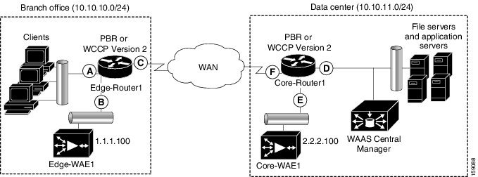
表 5-3 に、PBR または WCCP バージョン 2 を使用して、透過的にトラフィックを WAE へリダイレクトするために設定する必要があるルータ インターフェイスの概要を示します。
(注![]() ) 図 5-5 では、冗長性(たとえば、冗長なルータ、スイッチ、WAE、WAAS Central Manager、およびルータ)が省略されています。
) 図 5-5 では、冗長性(たとえば、冗長なルータ、スイッチ、WAE、WAAS Central Manager、およびルータ)が省略されています。
ポリシーベース ルーティングの設定の例は、ブランチ オフィスに 1 台の WAE、データセンターに 1 台の WAE が存在する WAAS ネットワークで、トラフィック リダイレクション方式として PBR を設定する方法を示しています(図 5-5 参照)。
(注![]() ) ルータで PBR を設定するために使用するコマンドは、ルータにインストールされている Cisco IOS Release によって変化します。ルータで使用している Cisco IOS Release 用に PBR を設定するために使用するコマンドについては、該当する Cisco IOS 設定ガイドを参照してください。
) ルータで PBR を設定するために使用するコマンドは、ルータにインストールされている Cisco IOS Release によって変化します。ルータで使用している Cisco IOS Release 用に PBR を設定するために使用するコマンドについては、該当する Cisco IOS 設定ガイドを参照してください。
ポリシーベース ルーティングの設定
このセクションの例は、ブランチ オフィスに 1 台の WAE、データセンターに 1 台の WAE が存在する WAAS ネットワークで、トラフィック リダイレクション方式として PBR を設定する方法を示しています(図 5-5 参照)。
TCP トラフィックを透過的に WAE へリダイレクトするように PBR を設定するには、次の手順に従ってください。
ステップ 1 ブランチ オフィスの Edge-Router で、拡張 IP アクセス リストを使用して、LAN インターフェイス(入力インターフェイス A)に関係するトラフィックを指定します。
a.![]() Edge-Router1 で、100 ~ 199 の範囲の拡張 IP アドレス リストを定義します。たとえば、Edge-Router1 でアクセス リスト 100 を作成します。
Edge-Router1 で、100 ~ 199 の範囲の拡張 IP アドレス リストを定義します。たとえば、Edge-Router1 でアクセス リスト 100 を作成します。
Edge-Router1(config)# ip access-list extended 100
b.![]() Edge-Router1 で、この特定のインターフェイスに関係するトラフィックを指定します。たとえば、任意の TCP ポート上の任意のローカル送信元アドレスから任意の送信先への任意の IP/TCP トラフィック(任意のブランチ オフィス クライアント用のトラフィック)に「関係がある」というマークを付けます。
Edge-Router1 で、この特定のインターフェイスに関係するトラフィックを指定します。たとえば、任意の TCP ポート上の任意のローカル送信元アドレスから任意の送信先への任意の IP/TCP トラフィック(任意のブランチ オフィス クライアント用のトラフィック)に「関係がある」というマークを付けます。
Edge-Router1(config-ext-nac1)# permit tcp 10.10.10.0 0.0.0.255 any
–![]() あるいは、送信元 IP サブネット、送信先 IP アドレス、および TCP ポート番号を定義して、選択的にトラフィックに「関係がある」というマークを付けることができます。たとえば、TCP ポート 135 と 80 上の任意のローカル送信元アドレスから任意の送信先への IP/TCP トラフィックに「関係がある」というマークを付けます。
あるいは、送信元 IP サブネット、送信先 IP アドレス、および TCP ポート番号を定義して、選択的にトラフィックに「関係がある」というマークを付けることができます。たとえば、TCP ポート 135 と 80 上の任意のローカル送信元アドレスから任意の送信先への IP/TCP トラフィックに「関係がある」というマークを付けます。
Edge-Router1(config-ext-nac1)# permit tcp 10.10.10.0 0.0.0.255 any eq 135
Edge-Router1(config-ext-nac1)# permit tcp 10.10.10.0 0.0.0.255 any eq 80
ステップ 2 ブランチ オフィスの Edge-Router1 で、拡張 IP アクセス リストを使用して、WAN インターフェイス(出力インターフェイス C)に関係するトラフィックを指定します。
a.![]() Edge-Router1 で、100 ~ 199 の範囲内で拡張 IP アクセス リストを定義し、たとえば Edge-Router1 にアクセス リスト 101 を作成します。
Edge-Router1 で、100 ~ 199 の範囲内で拡張 IP アクセス リストを定義し、たとえば Edge-Router1 にアクセス リスト 101 を作成します。
Edge-Router1(config)# ip access-list extended 101
b.![]() Edge-Router1 で、WAN インターフェイスに関係するトラフィックを指定します。
Edge-Router1 で、WAN インターフェイスに関係するトラフィックを指定します。
–![]() たとえば、ローカル デバイスへの任意の IP/TCP トラフィックに「関係がある」というマークを付けます。
たとえば、ローカル デバイスへの任意の IP/TCP トラフィックに「関係がある」というマークを付けます。
Edge-Router1(config-ext-nac1)# permit tcp any 10.10.10.0 0.0.0.255
–![]() あるいは、送信元 IP サブネット、送信先 IP アドレス、および TCP ポート番号を定義して、選択的にトラフィックに「関係がある」というマークを付けることができます。たとえば、TCP ポート 135 と 80 上の任意のローカル送信元アドレスと任意の送信先への IP/TCP トラフィックに「関係がある」というマークを付けます。
あるいは、送信元 IP サブネット、送信先 IP アドレス、および TCP ポート番号を定義して、選択的にトラフィックに「関係がある」というマークを付けることができます。たとえば、TCP ポート 135 と 80 上の任意のローカル送信元アドレスと任意の送信先への IP/TCP トラフィックに「関係がある」というマークを付けます。
Edge-Router1(config-ext-nac1)# permit tcp any 10.10.10.0 0.0.0.255 eq 135
Edge-Router1(config-ext-nac1)# permit tcp any 10.10.10.0 0.0.0.255 eq 80
ステップ 3 データセンターの Core-Router1 で、拡張 IP アクセス リストを使用して、LAN インターフェイス(入力インターフェイス D)に関係するトラフィックを指定します。
a.![]() Core-Router1 で、100 ~ 199 の範囲内で拡張 IP アクセス リストを定義し、たとえば Core-Router1 にアクセス リスト 102 を作成します。
Core-Router1 で、100 ~ 199 の範囲内で拡張 IP アクセス リストを定義し、たとえば Core-Router1 にアクセス リスト 102 を作成します。
Core-Router1(config)# ip access-list extended 102
b.![]() Core-Router1 で、LAN インターフェイスに関係するトラフィックを指定します。
Core-Router1 で、LAN インターフェイスに関係するトラフィックを指定します。
–![]() たとえば、任意の TCP ポート上の任意のローカル デバイスから任意の送信先へ送信される任意の IP/TCP トラフィック(たとえば、データセンターの任意のファイル サーバまたはアプリケーション サーバから送信されるトラフィック)に「関係がある」というマークを付けます。
たとえば、任意の TCP ポート上の任意のローカル デバイスから任意の送信先へ送信される任意の IP/TCP トラフィック(たとえば、データセンターの任意のファイル サーバまたはアプリケーション サーバから送信されるトラフィック)に「関係がある」というマークを付けます。
Core-Router1(config-ext-nac1)# permit tcp 10.10.11.0 0.0.0.255 any
–![]() あるいは、送信元 IP サブネット、送信先 IP アドレス、および TCP ポート番号を定義して、選択的にトラフィックに「関係がある」というマークを付けることができます。たとえば、TCP ポート 135 および 80 上の任意のローカル デバイスから任意の送信先への IP/TCP トラフィックに選択的に「関係がある」というマークを付けます。
あるいは、送信元 IP サブネット、送信先 IP アドレス、および TCP ポート番号を定義して、選択的にトラフィックに「関係がある」というマークを付けることができます。たとえば、TCP ポート 135 および 80 上の任意のローカル デバイスから任意の送信先への IP/TCP トラフィックに選択的に「関係がある」というマークを付けます。
Core-Router1(config-ext-nac1)# permit tcp 10.10.11.0 0.0.0.255 any eq 135
Core-Router1(config-ext-nac1)# permit tcp 10.10.11.0 0.0.0.255 any eq 80
ステップ 4 データセンターの Core-Router1 で、拡張 IP アクセス リストを使用して、WAN インターフェイス(出力インターフェイス F)に関係するトラフィックを指定します。
a.![]() Core-Router1 で、100 ~ 199 の範囲内で拡張アクセス リストを定義し、たとえば Core-Router1 にアクセス リスト 103 を作成します。
Core-Router1 で、100 ~ 199 の範囲内で拡張アクセス リストを定義し、たとえば Core-Router1 にアクセス リスト 103 を作成します。
Core-Router1(config)# ip access-list extended 103
b.![]() Core-Router1 で、WAN インターフェイス用のトラフィックに「関係がある」というマークを付けます。
Core-Router1 で、WAN インターフェイス用のトラフィックに「関係がある」というマークを付けます。
–![]() たとえば、任意のローカル デバイスへ送信される任意の IP/TCP トラフィック(たとえば、データセンターの任意のファイル サーバまたはアプリケーション サーバへ送信されるトラフィック)に「関係がある」というマークを付けます。
たとえば、任意のローカル デバイスへ送信される任意の IP/TCP トラフィック(たとえば、データセンターの任意のファイル サーバまたはアプリケーション サーバへ送信されるトラフィック)に「関係がある」というマークを付けます。
Core-Router1(config-ext-nac1)# permit tcp any 10.10.11.0 0.0.0.255
–![]() あるいは、送信元 IP サブネット、送信先 IP アドレス、および TCP ポート番号を定義して、選択的にトラフィックに「関係がある」というマークを付けることができます。たとえば、TCP ポート 135 と 80 上の任意のローカル送信元アドレスへの IP/TCP トラフィックに「関係がある」というマークを付けます。
あるいは、送信元 IP サブネット、送信先 IP アドレス、および TCP ポート番号を定義して、選択的にトラフィックに「関係がある」というマークを付けることができます。たとえば、TCP ポート 135 と 80 上の任意のローカル送信元アドレスへの IP/TCP トラフィックに「関係がある」というマークを付けます。
Core-Router1(config-ext-nac1)# permit tcp any 10.10.11.0 0.0.0.255 eq 135
Core-Router1(config-ext-nac1)# permit tcp any 10.10.11.0 0.0.0.255 eq 80
ステップ 5 ブランチ オフィスの Edge-Router1 に PBR ルート マップを定義します。
a.![]() LAN インターフェイス(入力インターフェイス)用のルート マップを定義します。次の例では、WAAS-EDGE-LAN ルート マップの作成方法を示しています。
LAN インターフェイス(入力インターフェイス)用のルート マップを定義します。次の例では、WAAS-EDGE-LAN ルート マップの作成方法を示しています。
Edge-Router1(config)# route-map WAAS-EDGE-LAN permit
b.![]() WAN インターフェイス(出力インターフェイス)用のルート マップを定義します。
WAN インターフェイス(出力インターフェイス)用のルート マップを定義します。
次の例では、WAAS-EDGE-WAN ルート マップの作成方法を示しています。
Edge-Router1(config)# route-map WAAS-EDGE-WAN permit
match コマンドを使用して、Edge-Router1 が、どのトラフィックが WAN インターフェイスに関係があるかを決定するために使用する拡張 IP アクセス リストを指定します。 match コマンドを指定しない場合、ルート マップはすべてのパケットに適用されます。
次の例では、WAN インターフェイスに関係があるトラフィックを決定するための基準としてアクセス リスト 101 を使用するように Edge-Router1 を設定する方法を示しています。
Edge-Router1(config-route-map)# match ip address 101
(注![]() ) ip address コマンド オプションは、1 つまたは複数の標準または拡張アクセス リストで許可される送信元または送信先 IP アドレスを照合します。
) ip address コマンド オプションは、1 つまたは複数の標準または拡張アクセス リストで許可される送信元または送信先 IP アドレスを照合します。
次の例では、指定した基準と一致するパケットをネクスト ホップ(IP アドレスが 1.1.1.100 の Edge-WAE1)へ送信するように Edge-Router1 を設定する方法を示してします。
Edge-Router1(config-route-map)# set ip next-hop 1.1.1.100
(注![]() ) 複数のブランチ オフィスの WAE がある場合、フェールオーバーの目的で別のブランチ オフィスの WAE の IP アドレスを指定して(たとえば、Edge-Router1 で set ip next-hop 1.1.1.101 コマンドを入力して)、フェールオーバーの目的でネクストホップ アドレス 1.1.1.101(Edge-WAE2 の IP アドレス)を指定できます。next-hop コマンドは、ロード バランシングではなく、フェールオーバーを目的としたものです。
) 複数のブランチ オフィスの WAE がある場合、フェールオーバーの目的で別のブランチ オフィスの WAE の IP アドレスを指定して(たとえば、Edge-Router1 で set ip next-hop 1.1.1.101 コマンドを入力して)、フェールオーバーの目的でネクストホップ アドレス 1.1.1.101(Edge-WAE2 の IP アドレス)を指定できます。next-hop コマンドは、ロード バランシングではなく、フェールオーバーを目的としたものです。
ステップ 6 データセンターの Core-Router1 にルート マップを作成します。
a.![]() LAN インターフェイス(入力インターフェイス)でルート マップを定義します。
LAN インターフェイス(入力インターフェイス)でルート マップを定義します。
次の例では、WAAS-CORE-LAN ルート マップの作成方法を示しています。
Core-Router1(config)# route-map WAAS-CORE-LAN permit
b.![]() WAN インターフェイス(出力インターフェイス)でルート マップを定義します。
WAN インターフェイス(出力インターフェイス)でルート マップを定義します。
次の例では、WAAS-CORE-WAN ルート マップの作成方法を示しています。
Core-Router1(config)# route-map WAAS-CORE-WAN permit
match コマンドを使用して、Core-Router1 が、どのトラフィックが WAN インターフェイスに関係があるかを決定するために使用する拡張 IP アクセス リストを指定します。 match コマンドを入力しない場合、ルート マップはすべてのパケットに適用されます。次の例では、WAN インターフェイスに関係があるトラフィックを決定するための基準としてアクセス リスト 103 を使用するように Core-Router1 を設定する方法を示しています。
Core-Router1(config-route-map)# match ip address 103
次の例では、指定した基準と一致するパケットをネクスト ホップ(IP アドレスが 2.2.2.100 の Core-WAE1)へ送信するように Core-Router1 を設定する方法を示してします。
Core-Router1(config-route-map)# set ip next-hop 2.2.2.100
(注![]() ) 複数のデータセンターの WAE がある場合、フェールオーバーの目的で別のデータセンターの WAE の IP アドレスを指定して(たとえば、Core-Router1 で set ip next-hop 2.2.2.101 コマンドを入力して)、フェールオーバーの目的でネクストホップ アドレス 2.2.2.101(Core-WAE2 の IP アドレス)を指定できます。next-hop コマンドは、ロード バランシングではなく、フェールオーバーを目的としたものです。
) 複数のデータセンターの WAE がある場合、フェールオーバーの目的で別のデータセンターの WAE の IP アドレスを指定して(たとえば、Core-Router1 で set ip next-hop 2.2.2.101 コマンドを入力して)、フェールオーバーの目的でネクストホップ アドレス 2.2.2.101(Core-WAE2 の IP アドレス)を指定できます。next-hop コマンドは、ロード バランシングではなく、フェールオーバーを目的としたものです。
ステップ 7 ブランチ オフィスの Edge-Router1 の LAN インターフェイス(入力インターフェイス)と WAN インターフェイス(出力インターフェイス)にルート マップを適用します。
a.![]() Edge-Router1 で、インターフェイス コンフィギュレーション モードを開始します。
Edge-Router1 で、インターフェイス コンフィギュレーション モードを開始します。
Edge-Router1(config)# interface FastEthernet0/0.10
b.![]() LAN ルータ インターフェイスが PBR 用の WAAS-EDGE-LAN ルート マップを使用するように指定します。
LAN ルータ インターフェイスが PBR 用の WAAS-EDGE-LAN ルート マップを使用するように指定します。
Edge-Router1(config-if)# ip policy route-map WAAS-EDGE-LAN
c.![]() インターフェイス コンフィギュレーション モードを開始します。
インターフェイス コンフィギュレーション モードを開始します。
Edge-Router1(config-if)# interface Serial0
d.![]() WAN ルータ インターフェイスが PBR 用の WAAS-EDGE-WAN ルート マップを使用するように指定します。
WAN ルータ インターフェイスが PBR 用の WAAS-EDGE-WAN ルート マップを使用するように指定します。
Edge-Router1(config-if)# ip policy route-map WAAS-EDGE-WAN
ステップ 8 データセンターの Core-Router1 の LAN インターフェイス(入力インターフェイス)と WAN インターフェイス(出力インターフェイス)にルート マップを適用します。
a.![]() Core-Router1 で、インターフェイス コンフィギュレーション モードを開始します。
Core-Router1 で、インターフェイス コンフィギュレーション モードを開始します。
Core-Router1(config)# interface FastEthernet0/0.10
b.![]() LAN ルータ インターフェイスが PBR 用の WAAS-CORE-LAN ルート マップを使用するように指定します。
LAN ルータ インターフェイスが PBR 用の WAAS-CORE-LAN ルート マップを使用するように指定します。
Core-Router1(config-if)# ip policy route-map WAAS-CORE-LAN
c.![]() インターフェイス コンフィギュレーション モードを開始します。
インターフェイス コンフィギュレーション モードを開始します。
Core-Router1(config-if)# interface Serial0
d.![]() WAN ルータ インターフェイスが PBR 用の WAAS-CORE-WAN ルート マップを使用するように指定します。
WAN ルータ インターフェイスが PBR 用の WAAS-CORE-WAN ルート マップを使用するように指定します。
Core-Router1(config-if)# ip policy route-map WAAS-CORE-WAN
PBR のネクストホップが使用できるかどうかを確認する方法
PBR を使用してトラフィックを透過的に WAE へリダイレクトするときは、次のいずれかの方法を使用して、WAE の PBR のネクストホップが使用できるかどうかを確認することを推奨します。選択する方法は、ルータで使用している Cisco IOS ソフトウェアのバージョンと WAE の配置によって異なります。ただし、可能な限り、方法 2 を使用してください。
- 方法 1:デバイスは、WAE を CDP ネイバー(直接接続されている)と見なすと、CDP と ICMP を使用して WAE が動作していることを確認できます。詳細については、方法 1:CDP を使用して WAE が動作していることを確認するを参照してください。
- 方法 2(推奨方法):Cisco IOS ソフトウェア Release 12.4 以降が動作しているデバイスが WAE を CDP ネイバーと見なさない場合は、WAE が ICMP エコーを使用して動作していることを確認できる IP サービス レベル契約(SLA)を使用します。詳細については、方法 2:IP SLA を使用して、WAE が ICMP エコー検査を使用して動作していることを確認するを参照してください。
- 方法 3:Cisco IOS ソフトウェア Release 12.4 以降が動作しているデバイスが WAE を CDP ネイバーと見なさない場合は、IP SLA を使用して、WAE が TCP 接続試行を使用して動作していることを確認します。詳細については、方法 3:IP SLA を使用して、WAE が TCP 接続試行を使用して動作していることを確認するを参照してください。
(注![]() ) この項で、デバイスは、PBR を使用してトラフィックを透過的に WAE へリダイレクトするように設定されたルータまたはスイッチのことを指しています。
) この項で、デバイスは、PBR を使用してトラフィックを透過的に WAE へリダイレクトするように設定されたルータまたはスイッチのことを指しています。
PBR を使用するように設定されたデバイスが WAE を CDP ネイバーと見なすかどうかを確認するには、デバイスで show cdp neighbors コマンドを入力します。デバイスが WAE を CDP 隣接と見なす場合、WAE は show cdp neighbors コマンドの出力に表示されます。
方法 1:CDP を使用して WAE が動作していることを確認する
PBR を使用するように設定されたデバイスが WAE を CDP ネイバー(WAE がデバイスに直接接続されている)と見なす場合は、CDP と ICMP を使用して PBR のネクスト ホップとして WAE を使用できるかどうかを確認できます。
次の例は、この方法を使用して、PBR のネクストホップとして WAE を使用できるかどうかを確認する方法を示しています。CDP を使用する必要があるときに設定される LAN ルート マップと WAN ルート マップのそれぞれについて、次の設定プロセスを完了する必要があります。
CDP を使用して WAE が動作していることを確認するには、次の手順に従ってください。
ステップ 1 PBR が設定されているルータ(たとえば、ブランチ オフィスの Edge-Router1 ルータ)で、コンフィギュレーション モードを開始し、CDP を有効にします。
Edge-Router1(config)# cdp run
ステップ 2 すでにルータに作成されている WAAS-EGDE-LAN ルート マップ用のルート マップ コンフィギュレーション モードを有効にします。
Edge-Router1(config)# route-map WAAS-EDGE-LAN permit
ステップ 3 CDP を使用して設定済みのネクストホップ アドレスが使用できるかどうかを確認するようにルータを設定します。
Edge-Router1(config-route-map)# set ip next-hop verify-availability
ステップ 4 ルータが PBR を使用してトラフィックをリダイレクトするようにしたい WAE(たとえば、ブランチ オフィスの Edge-WAE1)で、CDP を有効にします。
Edge-WAE1(config)# cdp enable
(注![]() ) PBR を設定し、複数の WAE があり、方法 1 を使用して PBR のネクストホップとして WAE が使用できることを確認する場合、前のプロセスを完了したら、追加の設定は不要です。
) PBR を設定し、複数の WAE があり、方法 1 を使用して PBR のネクストホップとして WAE が使用できることを確認する場合、前のプロセスを完了したら、追加の設定は不要です。
方法 2:IP SLA を使用して、WAE が ICMP エコー検査を使用して動作していることを確認する
IP SLA と ICMP を使用して(推奨方式)、PBR のネクストホップとして WAE が使用できることを確認するには、次の手順に従ってください。
ステップ 1 ブランチ オフィスの Edge-Router1 ルータで、このルータですでに設定されている WAAS-EDGE-LAN ルート マップ用のルート マップ コンフィギュレーション モードを開始します。
Edge-Router1(config)# route-map WAAS-EDGE-LAN permit
ステップ 2 トラフィックの一致条件を指定します。次の例では、一致条件にアクセス リスト番号 105 が指定されます。
Edge-Router1(config)# match ip address 105
ステップ 3 IP SLA 追跡インスタンス番号 1 を使用してネクストホップ WAE(たとえば、IP アドレスが 1.1.1.100 で Edge-WAE1 という名前のブランチ オフィスの WAE)が使用できることを確認するように、ルート マップを設定します。
Edge-Router1(config-route-map)# set ip next-hop verify-availability 1.1.1.100 track 1
(注![]() ) ブランチ オフィスのエッジ ルータと、PBR を使用してトラフィックを WAE へリダイレクトするように設定されているデータセンターのコア ルータに設定されている各ルート マップについて、set ip next-hop verify-availability コマンドを入力します。
) ブランチ オフィスのエッジ ルータと、PBR を使用してトラフィックを WAE へリダイレクトするように設定されているデータセンターのコア ルータに設定されている各ルート マップについて、set ip next-hop verify-availability コマンドを入力します。
ステップ 4 IP SLA 追跡インスタンス 1 を設定します。
Edge-Router1(config-route-map)# exit
Edge-Router1(config)# ip sla 1
Edge-Router1(config-ip-sla)#
ステップ 5 指定のソース インターフェイスを使用し、Edge-WAE1 をエコーするようにルータを設定します。
Edge-Router1(config-ip-sla)# icmp-echo 1.1.1.100 source-interface FastEthernet 0/0.20
ステップ 6 20 秒周期でエコーを実行するようにルータを設定します。
Edge-Router1(config-ip-sla)# frequency 20
Edge-Router1(config-ip-sla)# exit
ステップ 7 ただちに開始し、継続的に動作するように、IP SLA 追跡インスタンス 1 のスケジュールを設定します。
Edge-Router1(config)# ip sla schedule 1 life forever start-time now
ステップ 8 IP SLA 追跡インスタンス 1 で定義されているデバイスを追跡するように、IP SLA 追跡インスタンス 1 を設定します。
Edge-Router1(config)# track 1 rtr 1
(注![]() ) PBR を設定し、複数の WAE があり、方法 2 を使用して PBR のネクストホップとして WAE が使用できることを確認している場合は、WAE ごとに別々の IP SLA を設定し、IP SLA ごとに track コマンドを実行する必要があります。
) PBR を設定し、複数の WAE があり、方法 2 を使用して PBR のネクストホップとして WAE が使用できることを確認している場合は、WAE ごとに別々の IP SLA を設定し、IP SLA ごとに track コマンドを実行する必要があります。
方法 3:IP SLA を使用して、WAE が TCP 接続試行を使用して動作していることを確認する
PBR 用に設定され、Cisco IOS ソフトウェア Release 12.4 以降が動作しているデバイスが WAE を CDP ネイバーと見なさない場合は、IP SLA を使用して、WAE が TCP 接続試行を使用して動作していることを確認します。IP SLA を使用して、60 秒の固定周期で TCP 接続試行を使用して、WAE が PBR のネクスト ホップとして使用できることをモニタします。
PBR のネクストホップとして WAE が使用できることを確認するには、次の手順に従ってください。
ステップ 1 ブランチ オフィスの Edge-Router1 ルータで、このルータにすでに設定されている WAAS-EDGE-LAN ルート マップ用のルート マップ コンフィギュレーション モードを開始します。
Edge-Router1(config)# route-map WAAS-EDGE-LAN permit
ステップ 2 IP SLA 追跡インスタンス番号 1 を使用してネクストホップ WAE(たとえば、IP アドレスが 1.1.1.100 の Edge-WAE)が使用できることを確認するように、ルート マップを設定します。
Edge-Router1(config-route-map)# set ip next-hop verify-availability 1.1.1.100 track 1
(注![]() ) ブランチ オフィスのエッジ ルータと、PBR を使用してトラフィックを WAE へ透過的にリダイレクトするように設定されているデータセンターのコア ルータに設定されている各ルート マップについて、set ip next-hop verify-availability コマンドを入力します。
) ブランチ オフィスのエッジ ルータと、PBR を使用してトラフィックを WAE へ透過的にリダイレクトするように設定されているデータセンターのコア ルータに設定されている各ルート マップについて、set ip next-hop verify-availability コマンドを入力します。
ステップ 3 IP SLA 追跡インスタンス 1 を設定します。
Edge-Router1(config-route-map)# exit
Edge-Router1(config)# ip sla 1
ステップ 4 指定した送信先ポートと送信元ポートを使用し、60 秒の固定周期で TCP 接続試行を使用して WAE が使用できることをモニタするように、ルータを設定します。
Edge-Router1(config-ip-sla)# tcp-connect 1.1.1.100 80 source-port 51883 control disable
Edge-Router1(config-ip-sla)# exit
ステップ 5 ただちに開始し、永続的に動作するように、IP SLA 追跡インスタンス 1 のスケジュールを設定します。
Edge-Router1(config)# ip sla schedule 1 life forever start-time now
ステップ 6 IP SLA 追跡インスタンス 1 で定義されているデバイスを追跡するように、IP SLA 追跡インスタンス 1 を設定します。
Edge-Router1(config)# track 1 rtr 1
(注![]() ) PBR を設定し、複数の WAE があり、方法 3 を使用して PBR のネクストホップとして WAE が使用できることを確認している場合は、WAE ごとに別々の IP SLA を設定し、IP SLA ごとに track コマンドを実行する必要があります。
) PBR を設定し、複数の WAE があり、方法 3 を使用して PBR のネクストホップとして WAE が使用できることを確認している場合は、WAE ごとに別々の IP SLA を設定し、IP SLA ごとに track コマンドを実行する必要があります。
インライン モード代行受信の使用
- インライン代行受信に関する情報
- WAE 上でのインライン動作の有効化
- WAE 上でのインライン インターフェイスの設定
- ANC 上でのインライン動作の設定
- インライン インターフェイスの IP アドレスの設定
- インライン サポートの VLAN の設定
- インライン WAE のクラスタリングに関する情報
- シリアル インライン WAE 間でのピア最適化の無効化
インライン代行受信に関する情報
インライン モードを使用して、WAE は、物理的に透過的にトラフィックをクライアントとルータの間で代行受信できます。インライン モードを使用するには、Cisco WAE Inline Network Adapter またはインターフェイス モジュールがインストールされた WAE を使用します。このモードでは、WAE デバイスを最適化するトラフィックのパスに物理的に配置します。通常は、図 5-6で表示したスイッチとルータの間です。トラフィックのリダイレクションは必要ありません。
(注![]() ) インライン WAE デバイスを設置するときは、『Installing the Cisco WAE Inline Network Adapter』の「Cabling」の項または適切なプラットフォーム ハードウェア ガイドで説明しているケーブルの要件に従う必要があります。
) インライン WAE デバイスを設置するときは、『Installing the Cisco WAE Inline Network Adapter』の「Cabling」の項または適切なプラットフォーム ハードウェア ガイドで説明しているケーブルの要件に従う必要があります。
ピア WAE 上でのトラフィック代行受信メカニズムの任意の組み合わせがサポートされています。たとえば、インライン代行受信を、データセンター WAE 上のブランチ オフィス WAE と WCCP で使用できます。複雑なデータセンター導入の場合は、WAAS AppNav ソリューションによるハードウェアにより加速された WCCP 代行受信(Chapter 4, “AppNav の設定”を参照)の使用、または Cisco Application Control Engine(ACE)でのロード バランシングの使用を推奨します。
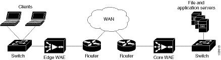
(注![]() ) インライン モードと WCCP リダイレクションは排他的です。WAE が WCCP 操作用に設定されている場合は、インライン モードを設定できません。インライン モードは、Cisco WAE Inline Network Adapter が WAE デバイスに設置されている場合のデフォルト モードですが、Cisco インターフェイス モジュールの搭載されたデバイスでは、インライン モードを明示的に設定する必要があります。
) インライン モードと WCCP リダイレクションは排他的です。WAE が WCCP 操作用に設定されている場合は、インライン モードを設定できません。インライン モードは、Cisco WAE Inline Network Adapter が WAE デバイスに設置されている場合のデフォルト モードですが、Cisco インターフェイス モジュールの搭載されたデバイスでは、インライン モードを明示的に設定する必要があります。
(注![]() ) インライン WAE は Central Manager として設定できますが、インライン代行受信機能は使用できません。
) インライン WAE は Central Manager として設定できますが、インライン代行受信機能は使用できません。
Cisco WAE Inline Network Adapter には、2 つまたは 4 つのイーサネット ポートがあり、Cisco インターフェイス モジュールには、2 ~ 8 つのイーサネット ポートがあり、AppNav コントローラ インターフェイス モジュールには、4 ~ 12 個のイーサネット ポートがあります。Cisco WAE Inline Network Adapter のポートは、常にインライン ポートとして設定されます。一方、インターフェイス モジュールのポートは、デフォルトでは通常のスタンドアロン ポートとして設定され、インライン ポートとしてこれらのポートを明示的に設定する必要があります。インライン ポートの各ペアは、論理インライン グループにグループ化されます。
各インライン グループには LAN 対応ポート 1 つと WAN 対応ポート 1 つがあります。通常、1 つのインライン グループだけを使用し、LAN 対応ポートをスイッチに接続し、WAN 対応ポートをルータに接続します。WAE を複数のルータに接続する必要があるネットワーク トポロジを使用している場合、追加のポートがあるアダプタまたはインターフェイス モジュールでは、追加のインターフェイスのグループが提供されます。グループで 1 つのインターフェイスを入力するトラフィックは、同じグループの別のインターフェイスを通じてデバイスを終了させます。
インライン ポートに対するハードウェア プラットフォームのサポートは、次のとおりです。
- WAVE-294:設置された 1 つの Cisco インターフェイス モジュール(2 ポート、4 ポート、または 8 ポート搭載)をサポートします。
- WAVE-594/694/7541/7571/8541:設置された 1 つの Cisco インターフェイス モジュール(2 ポート、4 ポート、または 8 ポート搭載)または Cisco AppNav コントローラ インターフェイス モジュール(4 ポートまたは 12 ポート搭載)をサポートしています。
(注![]() ) 2 ポートの 10 ギガビット Cisco インターフェイス モジュールは、インライン モードで使用できません。4 ポートの 10 ギガビット Cisco AppNav コントローラ インターフェイス モジュールは、WAVE-594 でのみサポートされます。
) 2 ポートの 10 ギガビット Cisco インターフェイス モジュールは、インライン モードで使用できません。4 ポートの 10 ギガビット Cisco AppNav コントローラ インターフェイス モジュールは、WAVE-594 でのみサポートされます。
インライン インターフェイスに IP アドレスを割り当てることができますが、必須ではありません。詳細については、インライン インターフェイスの IP アドレスの設定を参照してください。
インライン グループを通過するトラフィックは、最適化のために透過的に代行受信されます。最適化の必要のないトラフィックは、LAN/WAN インターフェイス間でブリッジされます。電源、ハードウェア、回復不能なソフトウェアの障害が発生した場合、ネットワーク アダプタは、自動的にバイパス モード(フェールクローズ)で動作し始めます。この場合、すべてのトラフィックは各グループで LAN と WAN のインターフェイス間で機械的にブリッジングされます。WAE の電源を切るか起動したときに、Cisco WAE Inline Network Adapter と Cisco インターフェイス モジュールもバイパス モードで動作します。また、インライン グループを手動でバイパス モードにすることもできます。
(注![]() ) AppNav コントローラ インターフェイス モジュールは、障害が発生した場合でもトラフィック フローを継続する自動バイパス モードをサポートしていません。ハイアベイラビリティを実現するためには、2 台以上の AppNav コントローラ インターフェイス モジュールを AppNav クラスタに導入する必要があります。AppNav ソリューションでのインライン モードの使用の詳細については、Chapter4, “AppNav の設定”を参照してください。
) AppNav コントローラ インターフェイス モジュールは、障害が発生した場合でもトラフィック フローを継続する自動バイパス モードをサポートしていません。ハイアベイラビリティを実現するためには、2 台以上の AppNav コントローラ インターフェイス モジュールを AppNav クラスタに導入する必要があります。AppNav ソリューションでのインライン モードの使用の詳細については、Chapter4, “AppNav の設定”を参照してください。
インライン モードはデフォルトで、すべての TCP トラフィックを受けるように設定されます。WAE が挿入されるネットワーク セグメントが 802.1Q のタグ付け(VLAN)トラフィックを実行中の場合、最初にすべての VLAN 上のトラフィックが受信されます。インライン代行受信は、各 VLAN に対して、有効または無効にできます。ただし、最適化のポリシーは、VLAN 上でカスタマイズできません。
インライン モードで動作している WAE デバイスを順番にクラスタ化すると、デバイスに障害が発生した場合にアベイラビリティを高めることができます。詳細については、インライン WAE のクラスタリングに関する情報を参照してください。
(注) WAE インライン グループがバイパス モードに入ると、接続されたスイッチとルータのポートを再初期化しなければならない場合があり、これによって数秒間トラフィックの WAE の通過が中断される可能性があります。
WAE がループの作成ができないような設定で展開される場合(つまり、スイッチとルータ間にスタンダードな形式で展開される場合)、スイッチ ポート上の PortFast を WAE が接続されるように設定します。PortFast によって、ポートは、スパニングツリー アルゴリズム(STA)の最初の数ステージをスキップでき、より早くパケット転送モードに移行できます。
WAE 上でのインライン動作の有効化
この項では、アプリケーション アクセラレータとして設定された、AppNav クラスタの一部である WAE 上でインライン設定を有効にし、設定する方法について説明します(AppNav クラスタの一部である WAE では、appnav-controller 代行受信方式のみを使用します)。AppNav コントローラとして設定された WAE 上でインラインの設定を行う場合は、ANC 上でのインライン動作の設定を参照してください。
Cisco インターフェイス モジュールを使用する WAVE-294/594/694/7541/7571/8541 デバイスでは、インターフェイス モジュール ポートは、デフォルトで通常のスタンドアロン動作に設定されます。インライン モードでデバイスを使用する場合は、インライン動作でポートを設定する必要があります。インライン モードを有効にすると、すべてのポートがインライン動作で設定され、ポートの各ペアがインライン グループに変換されます。
Cisco WAE Inline Network Adapter を使用する他の WAE デバイス上では、アダプタ上のポートが常にインライン モードで動作します。この設定ウィンドウを使用して、VLAN ID 接続検証を有効または無効にすることができます。これは、このような WAE デバイスに対して表示される唯一の設定です。
インライン動作を有効にし、一般的な設定を行うには、次の手順に従ってください。
ステップ 1 WAAS Central Manager メニューから、[Devices] > [ device-name ] を選択します。(デバイス グループからインライン動作を有効にすることはできません)。
ステップ 2 [Configure] > [Interception] > [Interception Configuration] を選択します。
(注![]() ) バージョン 5.0 よりも前の WAAS を使用しているデバイスを設定する場合は、[Configure] > [Interception] > [Inline] > [General Settings] を選択して、インライン一般設定を行います。設定ウィンドウの見た目は異なりますが、同様の設定があります。
) バージョン 5.0 よりも前の WAAS を使用しているデバイスを設定する場合は、[Configure] > [Interception] > [Inline] > [General Settings] を選択して、インライン一般設定を行います。設定ウィンドウの見た目は異なりますが、同様の設定があります。
[Interception Configuration] ウィンドウが表示されます。
ステップ 3 [Interception Method] ドロップダウン リストから、[Inline] を選択してインライン モードを有効にします。(バージョン 5.0 よりも前の WAAS を使用しているデバイスの場合、[Interception Method] ドロップダウン リストは表示されません)。
[Interception Configuration] ウィンドウがインライン設定で更新されます。(図 5-7)。
図 5-7 [Inline Interception Settings] ウィンドウ
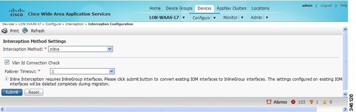
ステップ 4 [Inline Enable] チェックボックスを選択して、インライン動作を有効にします。
[Inline Enable] チェックボックスは、バージョン 5.0 よりも前の WAAS を使用していて、かつ Cisco インターフェイス モジュールが設置されている WAVE デバイスの場合にのみ表示されます。
ステップ 5 VLAN ID 接続チェックを有効にするには、[Vlan ID Connection Check] チェックボックスを選択します。無効にするには、このチェックボックスをオフにします。デフォルト設定はイネーブルです。
WAAS は VLAN ID を使用して、インライン インターフェイスで TCP フローの VLAN トラフィックを代行受信またはブリッジします。特定 TCP 接続で送信されたすべてのパケットの VLAN ID は一致する必要があります。異なる VLAN ID のパケットはブリッジされ、最適化されません。システムに、ある方向のトラフィック フローが他方向のトラフィック フローとは異なる VLAN ID を使用する非対称ルーティング トポロジが設定されている場合、トラフィックが最適化されていることを確認するために VLAN ID チェックを無効化できます。
ステップ 6 [Failover Timeout] ドロップダウン リストから、フェールオーバー タイムアウトを選択します(1 秒、5 秒、または 25 秒)。これは、デバイスまたは電源の障害が発生してから、インターフェイスがバイパス モードに移行するまでに待機する秒数を示します。デフォルト値は 1 秒です。
この項目は、AppNav コントローラ インターフェイス モジュール ではなく、Cisco インターフェイス モジュール を使用している WAVE デバイスにのみ表示されます。Cisco WAE Inline Network Adapter を使用しているデバイスには、[Inline Interface Settings] ウィンドウでフェールオーバー タイムアウトが設定されます(図 5-8)。この項目の名前はバージョン 5.0 よりも前の WAAS では [Time Out] になり、[VLAN ID Connection Check] 項目の前に表示されます。
ステップ 7 [Submit] をクリックします。すべてのインターフェイス モジュールのインターフェイスがインライン グループに変換され、インターフェイス モジュールの既存のインターフェイス設定が削除されることを確認するメッセージが表示されます。
基本的なデフォルト設定により、インライン グループが設定されます。インライン グループ設定を行うには、WAE 上でのインライン インターフェイスの設定を参照してください。
バージョン 5.0 よりも前の WAAS を実行しているデバイスの場合は、インライン モードを有効にした後に、インライン グループが [Inline Interfaces] リストに表示されるまでには、約 2 回のデータフィード ポーリング サイクル(デフォルトでは、約 10 分)かかります。
(注![]() ) いずれかのインターフェイス モジュール ポートがプライマリ インターフェイスとして設定されている場合は、インライン モードを有効にできません。プライマリ インターフェイスを変更し、このウィンドウに戻ってインライン モードを有効にします。
) いずれかのインターフェイス モジュール ポートがプライマリ インターフェイスとして設定されている場合は、インライン モードを有効にできません。プライマリ インターフェイスを変更し、このウィンドウに戻ってインライン モードを有効にします。
バージョン 5.0 よりも前の WAAS を実行しているデバイスの場合は、デフォルト以外の設定(スタンバイ グループ、ポート チャネル、BVI、速度、二重性、IP アドレス、ACL など)でインターフェイス モジュール上のいずれかのインターフェイスを設定した場合、インライン モードを有効にすることはできず、すべてのインターフェイスで設定のチェックを求める警告メッセージが表示されます。すべてのインターフェイス モジュールのインターフェイス(スロット 1)からすべての設定を削除した後に、このウィンドウに戻って、インライン モードを有効にする必要があります。
CLI からインライン動作を有効にするには、 interception-method inline グローバル コンフィギュレーション コマンドを使用します。
CLI から VLAN ID チェックを設定するには、インライン動作を有効にした後に inline vlan-id-connection-check グローバル コンフィギュレーション コマンドを使用します。
WAE 上でのインライン インターフェイスの設定
この項では、アプリケーション アクセラレータとして設定された、AppNav クラスタの一部である WAE 上でインライン設定を行う方法について説明します(AppNav クラスタの一部である WAE では、appnav-controller 代行受信方式のみを使用します)。AppNav コントローラ として設定された WAE 上でインライン設定を行うには、ANC 上でのインライン動作の設定 を参照してください。
インライン インターフェイス設定を行うには、次の手順に従ってください。
ステップ 1 WAAS Central Manager メニューから、[Devices] > [ device-name ] を選択します。(デバイス グループからはインライン インターフェイスを設定できません)。
ステップ 2 [Configure] > [Interception] > [Interception Configuration] を選択します。
(注![]() ) バージョン 5.0 よりも前の WAAS を使用しているデバイスを設定する場合は、[Configure] > [Interception] > [Inline] > [Inline Interfaces] を選択して、インライン インターフェイス設定を行います。設定ウィンドウの見た目は異なりますが、同様の設定があります。
) バージョン 5.0 よりも前の WAAS を使用しているデバイスを設定する場合は、[Configure] > [Interception] > [Inline] > [Inline Interfaces] を選択して、インライン インターフェイス設定を行います。設定ウィンドウの見た目は異なりますが、同様の設定があります。
[Inline Interfaces] ウィンドウが開き、デバイス上のインライン インターフェイス グループが表示されます。
ステップ 3 設定するインライン グループを選択し、[Edit] タスクバー アイコンをクリックします。(バージョン 5.0 より前の WAAS を使用しているデバイスでは、インターフェイスの横にある [Edit] アイコンをクリックします)。
[Edit Inline Settings] ウィンドウが表示され、特定のスロットとポート グループのインライン インターフェイス設定が表示されます。(図 5-8 を参照)。
図 5-8 [Edit Inline Settings] ウィンドウ
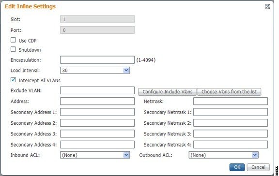
ステップ 4 インライン グループ インターフェイスで Cisco Discovery Protocol(CDP)を有効にするには、[Use CDP] チェックボックスを選択します。バージョン 5.0 よりも前の WAAS を使用しているデバイスの場合、[Use CDP] チェックボックスは表示されません。
有効にすると、CDP は、ネイバー デバイスのプロトコル アドレスを取得し、それらのデバイスのプラットフォームを検出します。また、ルータが使用するインターフェイスに関する情報を表示します。
[CDP Settings] ウィンドウから CDP を設定すると、CDP がすべてのインターフェイスでグローバルに有効になります。CDP の設定については、6 章「ネットワーク構成の設定」の CDP 設定の構成 を参照してください。
ステップ 5 [Shutdown] チェックボックスを選択して、インライン グループを停止します。この設定は、処理なしでトラフィックを LAN/WAN インターフェイス間でブリッジングします。
ステップ 6 [Encapsulation] フィールドで、WAE から出るトラフィックに割り当てる VLAN ID を入力します。VLAN ID は、ルータが予測する VLAN ID と一致するように設定する必要があります。
VLAN ID の詳細については、インライン インターフェイスの IP アドレスの設定を参照してください。
ステップ 7 [Load Interval] ドロップダウン リストから、統計のためのインターフェイスのポーリングおよびスループットの計算を行う間隔(秒単位)を選択します。デフォルトは 30 秒です。(バージョン 5.0 より前の WAAS を使用しているデバイスには、[Load Interval] の項目は表示されません)。
ステップ 8 [Intercept all VLANs] チェックボックスを選択して、インターフェイス グループのインライン代行受信を有効にします。WAE に Cisco WAE Inline Network Adapter が設置されている場合、インライン代行受信はデフォルトで有効になっていますが、Cisco インターフェイス モジュールが搭載されたデバイスでは明示的に有効にする必要があります(WAE 上でのインライン動作の有効化を参照してください)。
ステップ 9 [Exclude VLAN] フィールドで、最適化から除外する 1 つまたは複数の VLAN 範囲のリストを入力します。ネイティブ VLAN を除外するには、「native」と入力します。各 VLAN 範囲をカンマで区切ります。または、次に示す手順に従って、VLAN 範囲をリストから選択できます。
a.![]() インライン代行受信に含める VLAN リストがわかっている場合は、[Configure Include VLANs] をクリックします。このボタンは、内包する VLAN をカンマで区切ったリストの入力を要求するスクリプトを実行します。スクリプトは、除外対象のすべての VLAN のインバース リストを生成し、その後、ウィンドウを更新し、リストを [Exclude VLAN] フィールドに入力します。
インライン代行受信に含める VLAN リストがわかっている場合は、[Configure Include VLANs] をクリックします。このボタンは、内包する VLAN をカンマで区切ったリストの入力を要求するスクリプトを実行します。スクリプトは、除外対象のすべての VLAN のインバース リストを生成し、その後、ウィンドウを更新し、リストを [Exclude VLAN] フィールドに入力します。
b.![]() [Choose VLANs from the list] をクリックして、VLAN 範囲を選択します。[VLAN Range Assignments] ウィンドウが表示され、定義された VLAN 範囲を表示します。VLAN 範囲の定義については、インライン サポートの VLAN の設定に説明があります。
[Choose VLANs from the list] をクリックして、VLAN 範囲を選択します。[VLAN Range Assignments] ウィンドウが表示され、定義された VLAN 範囲を表示します。VLAN 範囲の定義については、インライン サポートの VLAN の設定に説明があります。
c.![]() 含めるか、または除外する VLAN 範囲を選択します。
含めるか、または除外する VLAN 範囲を選択します。
–![]() 最適化に含める各 VLAN 範囲の横にあるチェックボックスを選択し、[Include Vlan] タスクバー アイコンをクリックします。最適化に含まれないすべての VLAN は、除外されます。バージョン 5.0 よりも前の WAAS を使用しているデバイスの場合は、含める各 VLAN 範囲の横にある
最適化に含める各 VLAN 範囲の横にあるチェックボックスを選択し、[Include Vlan] タスクバー アイコンをクリックします。最適化に含まれないすべての VLAN は、除外されます。バージョン 5.0 よりも前の WAAS を使用しているデバイスの場合は、含める各 VLAN 範囲の横にある  をクリックします。アイコンは
  に変わります。
–![]() 最適化から除外する各 VLAN 範囲の横にあるチェックボックスを選択し、[Exclude Vlan] タスクバー アイコンをクリックします。バージョン 5.0 よりも前の WAAS を使用しているデバイスの場合は、最適化から除外する各 VLAN 範囲の横にある
最適化から除外する各 VLAN 範囲の横にあるチェックボックスを選択し、[Exclude Vlan] タスクバー アイコンをクリックします。バージョン 5.0 よりも前の WAAS を使用しているデバイスの場合は、最適化から除外する各 VLAN 範囲の横にある  をクリックします。アイコンは
  に変わります。
–![]() すべての選択をクリアするには、[Clear Selection] タスクバー アイコンをクリックします。バージョン 5.0 よりも前の WAAS を使用しているデバイスの場合は、タスクバーの
すべての選択をクリアするには、[Clear Selection] タスクバー アイコンをクリックします。バージョン 5.0 よりも前の WAAS を使用しているデバイスの場合は、タスクバーの  をクリックして最適化する有効なすべての VLAN 範囲を選択するか、タスクバーの
  をクリックして、すべての VLAN 範囲を最適化から除外します。
d.![]() [OK] をクリックします。バージョン 5.0 よりも前の WAAS を使用しているデバイスの場合は、[Submit] をクリックします。
[OK] をクリックします。バージョン 5.0 よりも前の WAAS を使用しているデバイスの場合は、[Submit] をクリックします。
ステップ 10 [Failover Timeout] ドロップダウン リストから、秒数 [1]、[3]、[5]、または [10] を選択します。デフォルト値は 1 秒です。この値は、バイパス モードで動作を開始する前に、WAE が待つ障害イベント後の秒数を設定します。バイパス モードでは、インターフェイス グループのいずれかのポートで受信されるすべてのトラフィックはグループの別のポートへ転送されます。
このチェックボックスは、.Cisco WAE Inline Network Adapter を使用するデバイスにのみ適用されます。Cisco インターフェイス モジュール を使用しているデバイスでは、フェールオーバー タイムアウトは [Inline Interception Settings] ウィンドウ(図 5-7)で設定され、このウィンドウには表示されません。
ステップ 11 速度およびモードのポート設定を次のように行います(これらの設定は、自動検知を使用する WAAS バージョン 5.0 以降を使用しているデバイス上の Cisco インターフェイス モジュールのインターフェイスでは使用されません)。
a.![]() デフォルトで有効になっている [AutoSense] チェックボックスの選択を解除します。
デフォルトで有効になっている [AutoSense] チェックボックスの選択を解除します。
b.![]() [Speed] ドロップダウン リストから、送信速度([10]、[100]、[1000]、または [10000] Mbps)を選択します。バージョン 5.0 よりも前の WAAS を使用している Cisco インターフェイス モジュールのファイバ ギガビット イーサネット インターフェイスに対しては、1000 Mbps を選択します。
[Speed] ドロップダウン リストから、送信速度([10]、[100]、[1000]、または [10000] Mbps)を選択します。バージョン 5.0 よりも前の WAAS を使用している Cisco インターフェイス モジュールのファイバ ギガビット イーサネット インターフェイスに対しては、1000 Mbps を選択します。
c.![]() [Mode] ドロップダウン リストから、送信モード([full-duplex] または [half-duplex])を選択します。バージョン 5.0 よりも前の WAAS を使用している Cisco インターフェイス モジュールのファイバ ギガビット イーサネット インターフェイスに対しては、full-duplex を選択します。
[Mode] ドロップダウン リストから、送信モード([full-duplex] または [half-duplex])を選択します。バージョン 5.0 よりも前の WAAS を使用している Cisco インターフェイス モジュールのファイバ ギガビット イーサネット インターフェイスに対しては、full-duplex を選択します。
(注![]() ) WAE、ルータ、スイッチ、またはその他のデバイスでは半二重接続を使用しないことを強く推奨します。半二重接続の場合はパフォーマンスが低下するので、使用は避けてください。各 Cisco WAE インターフェイスおよび隣接デバイス(ルータ、スイッチ、ファイアウォール、WAE)のポート設定を調べて、全二重接続が使用されていることを確認してください。
) WAE、ルータ、スイッチ、またはその他のデバイスでは半二重接続を使用しないことを強く推奨します。半二重接続の場合はパフォーマンスが低下するので、使用は避けてください。各 Cisco WAE インターフェイスおよび隣接デバイス(ルータ、スイッチ、ファイアウォール、WAE)のポート設定を調べて、全二重接続が使用されていることを確認してください。
ステップ 12 IP アドレスを割り当てる場合は、[Address] フィールドにインライン インターフェイスの IP アドレスを入力します。
ステップ 13 [Netmask] フィールドに、インライン インターフェイスのサブネット マスクを入力します。
ステップ 14 [Secondary Address] フィールドと [Secondary Netmask] フィールドに最大 4 つまでのセカンダリ IP アドレスとそれに対応するサブネット マスクを入力します。
複数の IP アドレスを設定することで、デバイスを複数のサブネットに置くことができ、データをルータでリダイレクトせずに、直接 WAAS デバイスから情報を要求するクライアントへ転送できるので、デバイスを使用して応答時間を最適化することができます。また、WAAS デバイスとクライアントは同じサブネット上に設定されるため、クライアントから WAAS デバイスを認識できます。
ステップ 15 [Default Gateway] フィールドで、デフォルト ゲートウェイ IP アドレスを入力します。WAAS バージョン 5.0 以降を使用しているデバイスの場合、[Default Gateway] フィールドは表示されません。
ステップ 16 (任意)[Inbound ACL] ドロップダウン リストから、着信パケットに適用する IP ACL を選択します。
ドロップダウン リストには、システムに設定されているすべての IP ACL が表示されています。
ステップ 17 (任意)[Outbound ACL] ドロップダウン リストから、発信パケットに適用する IP ACL を選択します。
ステップ 18 [OK] をクリックします。(バージョン 5.0 より前の WAAS を使用したデバイスでは、[Submit] をクリックします)。
ステップ 19 WAAS バージョン 5.0 以降の場合は、[Configure] > [Network] > [Default Gateway] を選択して、インライン インターフェイスのデフォルト ゲートウェイを設定します。
a.![]() [Default Gateway] フィールドで、デフォルト ゲートウェイ IP アドレスを入力します。
[Default Gateway] フィールドで、デフォルト ゲートウェイ IP アドレスを入力します。
CLI からインライン代行受信を設定するには、 interface InlineGroup グローバル コンフィギュレーション コマンドを使用できます。
ANC 上でのインライン動作の設定
この項では、AppNav コントローラ(ANC)として設定された WAAS デバイス上でインライン設定を有効にし、設定する方法について説明します。4 章「AppNav の設定」の AppNav Cluster ウィザードを使用した新しい AppNav クラスタの作成の説明に従って、AppNav クラスタのウィザードを使用してインライン ANC を設定し、インライン ブリッジ インターフェイスを作成することもできます。
アプリケーション アクセラレータとして設定された WAE 上でインラインの設定を行う場合は、WAE 上でのインライン動作の有効化を参照してください。
Cisco AppNav コントローラ インターフェイス モジュールを使用する WAVE-594/694/7541/7571/8541 デバイスでは、AppNav コントローラ インターフェイス モジュール ポートは、デフォルトで通常のスタンドアロン動作に設定されます。インライン モードでデバイスを使用する場合は、インライン動作でポートを設定し、インライン ブリッジ グループを作成する必要があります。インライン モードを有効にすると、すべてのポートがインライン動作で設定されます。
インライン動作を有効にし、インライン ブリッジ グループを設定するには、次の手順に従ってください。
ステップ 1 WAAS Central Manager メニューから、[Devices] > [ device-name ] を選択します。(デバイス グループからインライン動作を有効にすることはできません)。
ステップ 2 [Configure] > [Interception] > [Interception Configuration] を選択します。
[Interception Configuration] ウィンドウが表示されます。
ステップ 3 [Interception Method] ドロップダウン リストから、[Inline] を選択してインライン モードを有効にします。
ステップ 4 [Submit] をクリックしてインライン モードを有効にし、追加設定を使用してウィンドウを更新します。
すべての既存のブリッジ グループが表示されます。これには、ブリッジ グループの番号、プロトコル、リンク ステート プロパゲーション設定、VLAN 範囲、および含まれているインターフェイスが示されます。
ステップ 5 [Create Bridge] タスクバー アイコンをクリックします。
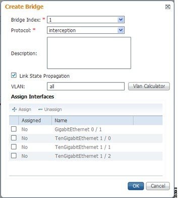
ステップ 6 [Bridge Index] ドロップダウン リストから、ブリッジ グループの番号を選択します。
ステップ 7 (任意)[Description] フィールドに、ブリッジ グループの説明を入力します。
ステップ 8 (任意)[ Link State Propagation] チェックボックスを選択して、リンク ステート プロパゲーションを有効にします。デフォルトではイネーブルです。
リンク ステート プロパゲーションとは、インライン ブリッジ グループの 1 つのインターフェイスがダウンした場合に、他のインターフェイスが自動的にシャットダウンされ、ネットワーク フェールオーバー方式が確実にトリガーされることを意味します。
ステップ 9 (オプション)代行受信に含める VLAN を設定します。最初は、すべての VLAN が含まれます。特定の VLAN 範囲を含める、または除外するには、次の手順に従ってください。
a.![]() [Vlan Calculator] をクリックします。
[Vlan Calculator] をクリックします。
b.![]() 代行受信に含める各 VLAN 範囲に対して、[Select Operation Type] ドロップダウン リストから [Add/Include] を選択します。[Vlan Range] フィールドで、対象に含める 1 つ以上の VLAN 範囲のカンマ区切りのリストを入力します。ネイティブ VLAN を含めるには、「native」と入力します。
代行受信に含める各 VLAN 範囲に対して、[Select Operation Type] ドロップダウン リストから [Add/Include] を選択します。[Vlan Range] フィールドで、対象に含める 1 つ以上の VLAN 範囲のカンマ区切りのリストを入力します。ネイティブ VLAN を含めるには、「native」と入力します。
c.![]() 代行受信に含める各 VLAN 範囲に対して、[Select Operation Type] ドロップダウン リストから [Except/Exclude] を選択します。[Vlan Range] フィールドで、除外する 1 つ以上の VLAN 範囲のカンマ区切りのリストを入力します。ネイティブ VLAN を除外するには、「native」と入力します。
代行受信に含める各 VLAN 範囲に対して、[Select Operation Type] ドロップダウン リストから [Except/Exclude] を選択します。[Vlan Range] フィールドで、除外する 1 つ以上の VLAN 範囲のカンマ区切りのリストを入力します。ネイティブ VLAN を除外するには、「native」と入力します。
ステップ 10 [Assign Interfaces] 領域で、このブリッジ グループに割り当てる 2 つのインターフェイスの横にあるチェック ボックスを選択し、[Assign] タスクバー アイコンをクリックします。割り当て済みのインターフェイスの割り当てを解除するには、割り当てを解除する各インターフェイスを選択し、[Unassign] タスクバー アイコンをクリックします。ブリッジ グループには、2 つの物理インターフェイスまたは 2 つのポート チャネル インターフェイス(または、これらの組み合わせ)を含めることができます。
ステップ 11 [OK] をクリックして、ブリッジ グループを作成します。
インライン インターフェイスの IP アドレスの設定
インライン グループ インターフェイスに IP アドレスを割り当てることができますが、必須ではありません。WAE 上でのインライン インターフェイスの設定で説明されている手順に従って、1 つのプライマリ IP アドレスと最大 4 つのセカンダリ IP アドレスを割り当てることができます。
インライン グループ インターフェイスを WAE のプライマリ インターフェイスとして設定するには、[Configure] > [Network] > [Network Interfaces] ウィンドウの [Primary Interface] ドロップダウン リストを使用します。
WAE のプライマリ インターフェイスがインライン グループ インターフェイスに設定され、管理トラフィックが個別の IP アドレス(同一のインライン グループ インターフェイスまたは組み込みインターフェイスのセカンダリ IP アドレス)に設定されているシナリオでは、WAAS Central Manager が管理トラフィック用に指定された IP アドレスの WAE と通信するように設定します。[Configure] > [Network] > [Management Interface Settings] メニュー項目を使用して、WAE 管理インターフェイスの設定を行います。バージョン 5.0 よりも前の WAAS の場合は、[ device-name ] > [Activation] ウィンドウの [Management IP] フィールドで、WAE 管理トラフィックの IP アドレスを設定します。
インライン モードで動作している WAE が、スイッチとルータ間の 802.1Q VLAN トランク回線に存在し、インライン インターフェイスに IP アドレスを設定している場合は、WAE の発信トラフィックに割り当てられる VLAN ID を設定する必要があります。VLAN ID は、ルータが予測する VLAN ID と一致するように設定する必要があります。
VLAN ID を割り当てるには、次のように、 encapsulation dot1Q インターフェイス コマンドを使用します。
この例は、VLAN ID 100 を WAE の発信トラフィックに割り当てる方法を示しています。VLAN ID の範囲は、1 ~ 4094 です。
(注) インライン トラフィックの VLAN ID を設定するには、encapsulation dot1Q インターフェイス コマンドを使用するか、または Central Manager メニュー項目([Configure] > [Interception] > [Interception Configuration])を使用します(WAE 上でのインライン インターフェイスの設定 を参照)。
VLAN ID がルータ サブインターフェイスによって予測された VLAN ID と一致しないと、インライン インターフェイス IP アドレスに接続できない場合があります。
インライン アダプタは、インライン グループ インターフェイスごとに 1 つの VLAN ID しかサポートしません。インライン インターフェイスの異なるサブネットのセカンダリ アドレスを設定している場合は、VLAN のルータ サブインターフェイスに同じセカンダリ アドレスを割り当てる必要があります。
IEEE 802.1Q トンネリングを使用すると、タグが追加されるときにフレーム サイズが 4 バイト増加します。したがって、デバイス MTU を最低でも 1504 バイト増やすことによって、トンネル化されたパケットが通過するすべてのスイッチでより大きなフレームを処理できるように設定する必要があります。
(注![]() ) IPv6 アドレスと dot1 q カプセル化で設定されている WAE 上のインライン インターフェイスが IPv6 デフォルト ゲートウェイとの通信を試みた場合、通信はつながりません。IPv4 アドレスと dot1 Q カプセル化で設定された同じデバイスが IPv4 デフォルト ゲートウェイとの通信を試みた場合は、通信はつながります。
) IPv6 アドレスと dot1 q カプセル化で設定されている WAE 上のインライン インターフェイスが IPv6 デフォルト ゲートウェイとの通信を試みた場合、通信はつながりません。IPv4 アドレスと dot1 Q カプセル化で設定された同じデバイスが IPv4 デフォルト ゲートウェイとの通信を試みた場合は、通信はつながります。
dot1Q カプセル化が無効になっている場合は、WAE(IPv6 または IPv4 が設定されている)は関連の IP タイプのデフォルト ゲートウェイに到達できます。
次の動作に関する考慮事項は、インライン インターフェイスでの IP アドレスの設定に適用されます。
- この機能は、ルーティング可能な基本インターフェイスをサポートし、組み込みインターフェイスに関連付けられたスタンバイ チャネルおよびポート チャネルの追加機能はサポートしません。
- すべてのトラフィックに対してインライン インターフェイスを使用するように WAE を設定している場合は、インライン代行受信を有効にする必要があります。有効にしないと、WAE はトラフィックを受信しません。
- WAE が、すべてのトラフィックに対してインライン インターフェイスを使用するように設定されており、メカニカル バイパス モードに切り替わった場合は、インライン インターフェイス IP アドレスを介して WAE にアクセスできなくなります。インライン インターフェイスがバイパス モードの場合にデバイスを管理するには、コンソール アクセスが必要となります。
- WAE にインライン インターフェイスの IP アドレスが設定されている場合、インターフェイスはそのアドレス宛てのトラフィックと ARP ブロードキャストだけを受信でき、マルチキャスト トラフィックは受信できません。
- HSRP グループに参加している 2 つのルータが 2 つのインライン グループを介して直接接続されている、HSRP を使用した構成の場合、アクティブなルータが故障すると、HSRP はすべてのクライアントを対象として動作します。ただし、管理トラフィックもインライン インターフェイスを使用するように設定されている場合、管理トラフィック用の WAE 自身の IP アドレスにはこの冗長性は適用されません。アクティブなルータが故障した場合、インライン インターフェイスは物理的に故障したルータ インターフェイスに接続されているため、WAE インライン IP アドレスには接続できなくなります。この場合は、スタンバイ ルータに接続された 2 番めのインライン グループ インターフェイスを通じて WAE に接続できます。管理トラフィック用の WAE 自身の IP アドレスに冗長性が必要な場合は、インライン インターフェイスではなく組み込みインターフェイスの IP アドレスを使用することを推奨します。
インライン サポートの VLAN の設定
最初、WAE はトラフィックをすべての VLAN から受信します。ある VLAN からのトラフィックを含めるまたは排除するように WAE を設定できます。排除された VLAN に対してトラフィックはグループで LAN/WAN インターフェイス間でブリッジングされ、処理されません。
インラインをサポートするように VLAN を設定するには、次の手順に従ってください。
ステップ 1 WAAS Central Manager メニューで、[Configure] > [Platform] > [Vlans] を選択します。
[Vlans] ウィンドウが表示され、定義された VLAN をリストします。このリストから、次の作業を実行できます。
ステップ 2 [Add VLAN] タスクバー アイコンをクリックします。[VLAN] ペインが表示されます。
ステップ 3 [Name] フィールドで、VLAN リストの名前を入力します。
ステップ 4 [Ranges] フィールドで、1 つまたは複数の VLAN 範囲のリストを入力します。各 VLAN 範囲をカンマで分離します(スペースはなし)。WAE 上でのインライン インターフェイスの設定の説明に従って、インライン インターフェイス グループを設定するときに、VLAN 範囲のこのリストは、最適化に含めたり除外したりすることができます。このフィールドには、「native」を指定できません。
VLAN リスト作成のこの機能が提供され、VLAN リストをグローバルに設定できます。インライン インターフェイス用に VLAN を設定するには、この機能を使用する必要はありません。WAE 上でのインライン インターフェイスの設定の説明に従って、インライン インターフェイス設定ウィンドウで VLAN を直接設定できます。
インライン WAE のクラスタリングに関する情報
インライン モードで動作している WAE デバイスを順番にクラスタ化すると、デバイスに障害が発生した場合にデータセンターのアベイラビリティを高めることができます。現在の最適化デバイスに問題が発生した場合、インライン グループはシャットダウンするか、またはデバイスが過負荷になり、クラスタ内の 2 番目の WAE デバイスが最適化サービスを提供します。拡張またはロード バランシングの目的でシリアル インライン クラスタに WAE デバイスを導入する方法は、サポートされていません。
(注![]() ) 個々のアプリケーション アクセラレータではなく、TFO 過負荷で過負荷フェールオーバーが発生します。これは、一時的な過負荷防止を目的としています。過負荷状態で WAE の実行を継続すると、頻繁に過負荷フェールオーバーが発生するため、推奨しません。
) 個々のアプリケーション アクセラレータではなく、TFO 過負荷で過負荷フェールオーバーが発生します。これは、一時的な過負荷防止を目的としています。過負荷状態で WAE の実行を継続すると、頻繁に過負荷フェールオーバーが発生するため、推奨しません。
シリアル クラスタは、連続的にトラフィック パスで接続される 2 つの WAE デバイスで構成されます。1 つのデバイスの WAN ポートは、図 5-10 に示すように、次のデバイスの LAN ポートなどに接続されます。
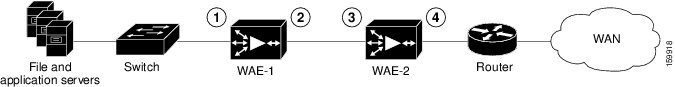
|
|
|
||
|
|
|
シリアル クラスタでは、スイッチとルータの間のすべてのトラフィックは、すべてのインライン WAE を通過します。図 5-10 では、TCP 接続は WAE-1 によって最適化されます。WAE-1 に障害が発生すると、トラフィックはバイパスされ、WAE-2 によって最適化されます。
シリアルでクラスタ化された WAE のポリシー設定は同じである必要があります。また、クラスタ内の両方の WAE に同じデバイスを使用することを推奨します。
各 WAE でインライン WAE をシリアルでクラスタ化する場合、クラスタ内の他の WAE のアドレスを非最適化ピアとして設定する必要があります。これにより、シリアル クラスタの 2 つのピア WAE 間の最適化が無効となります。これは、ユーザが WAN リンクの各側の WAE ピア間のみでの最適化を希望しているためです。ピア間での最適化を無効にする方法の詳細については、シリアル インライン WAE 間でのピア最適化の無効化を参照してください。
シリアル インライン WAE 間でのピア最適化の無効化
シリアル クラスタの WAE 間のピア最適化を無効にするには、次の手順に従ってください。
ステップ 1 WAAS Central Manager メニューから、[Devices] > [ device-name ] を選択します。(デバイス グループからはピアを設定できません)。
ステップ 2 [Configure] > [Peers] > [Peer Settings] を選択します。
[Peer Settings] ウィンドウが表示されます(図 5-11 を参照)。
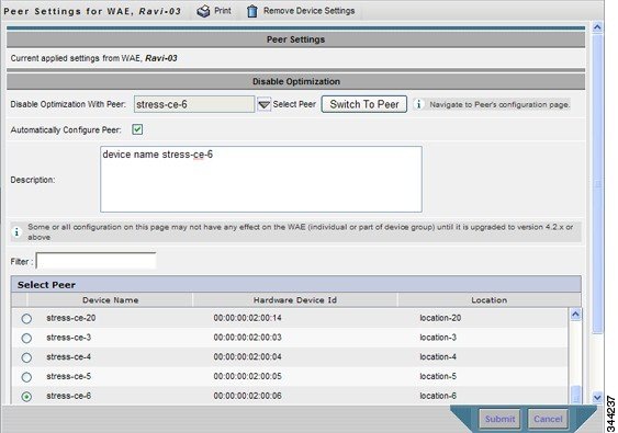
ステップ 3 ウィンドウの下部にある [Select Peer] トライアングル コントロールをクリックして、この Central Manager で登録された他の WAE を表示します([Select Peer] エリアを参照)。
ステップ 4 [Select Peer] エリアで、現在のデバイスのシリアル ピアの横にあるオプション ボタンをクリックします。ピア デバイスの名前が [Disable Optimization With Peer] フィールドに表示されます。
デバイス リストをフィルタする場合は、[Filter] フィールドに文字列を入力します。文字を入力すると、デバイス リストが動的にフィルタされ、デバイス名またはハードウェア デバイス ID にフィルタ文字列が含まれるデバイスのみが対象となります。
ステップ 5 [Automatically Configure Peer] チェックボックスを選択すると、Central Manager が類似の設定を使用して他のピアを設定し、現在のデバイスを使用して最適化を無効にすることができます。
このチェック ボックスを選択しない場合、他のピアを手動で設定して、現在のデバイスを使用して最適化を無効にする必要があります。変更内容を送信した後、[Switch to Peer] ボタンをクリックして、このピア デバイスに関する同じ設定ページへ進みます。
ステップ 6 [Description] フィールドにピアの説明を入力します。デフォルトの説明は、ピアのデバイス名です。
CLI からシリアル ピア最適化を無効にするには、 no peer device-id グローバル コンフィギュレーション コマンドを使用します。シリアル ピア最適化を再度有効にするには、 peer device-id グローバル コンフィギュレーション コマンドを使用します。
Central Manager に登録されているすべてのシリアル クラスタ ペアのステータスを表示するには、WAAS Central Manager メニューで、[Configure] > [Global] > [Peer Settings] を選択します。図 5-12 に示すように、[Peer Settings] ステータス ウィンドウが表示されます。
図 5-12 [Peer Settings For All Devices] ウィンドウ
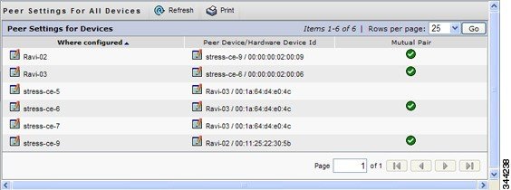
ウィンドウには、ピア最適化を設定した各 WAE が表示されます。各シリアル クラスタ ペアに対して 2 つのエントリがあり、エントリの [Mutual Pair] カラムにチェック マークが付いていることを確認します。ペアの各 WAE にはエントリが設定されていることが必要です(たとえば、上図の最初と最後のエントリ)。
エントリの [Mutual Pair] カラムにチェック マークが付いていない場合は、シリアル ピアが設定されているが、このピアが最初のデバイスを使用してシリアル ピアとして同様に設定されていない WAE を示します。
AppNav 代行受信の設定
AppNav 導入の一部であり、かつ AppNav クラスタの WAAS ノード(WN)として設定されている WAE の場合は、WAE を設定して appnav-controller 代行受信方式を使用する必要があります。これらの WN は ANC からのトラフィックのみを受信し、ルータからは直接受信しません。ネットワーク トラフィックを代行受信する代行受信方式(WCCP、PBR、インラインなど)の設定は、ANC デバイス上で行います。AppNav 導入の詳細については、Chapter4, “AppNav の設定”を参照してください。
(注![]() ) ISR-WAAS デバイスは AppNav コントローラの代行受信方式だけをサポートします。
) ISR-WAAS デバイスは AppNav コントローラの代行受信方式だけをサポートします。
Central Manager のウィザードを使用して AppNav クラスタを作成した場合、または AppNav クラスタのウィンドウを使用して WN をクラスタに追加した場合は、Central Manager により、WN が appnav-controller 代行受信方式を使用して自動的に設定されます。WN をクラスタに追加した後には、その代行受信方式を変更できません。
WN 上での appnav-controller 代行受信を手動で設定するには、次の手順に従ってください。
ステップ 1 WAAS Central Manager メニューから、[Devices] > [ device-name ] を選択します。
ステップ 2 [Configure] > [Interception] > [Interception Configuration] を選択します。[Interception Configuration] ウィンドウが表示されます。
ステップ 3 [Interception Method] ドロップダウン リストから、[appnav-controller] を選択して appnav-controller 代行受信方式を有効にします。
 フィードバック