Cisco Catalyst IW6300 Heavy Duty Series Access Point Hardware Installation Guide
Bias-Free Language
The documentation set for this product strives to use bias-free language. For the purposes of this documentation set, bias-free is defined as language that does not imply discrimination based on age, disability, gender, racial identity, ethnic identity, sexual orientation, socioeconomic status, and intersectionality. Exceptions may be present in the documentation due to language that is hardcoded in the user interfaces of the product software, language used based on RFP documentation, or language that is used by a referenced third-party product. Learn more about how Cisco is using Inclusive Language.
This publication explains the steps for installing the Cisco Catalyst IW6300 Heavy Duty Series Access Point.
Audience
This publication is for the person installing and configuring an access point for the first time. The installer should be
familiar with network structures, terms, and concepts.
For installations in a hazardous locations environment, please refer to Getting Started and Product Document of Compliance
for the Cisco Catalyst IW6300 Heavy Duty Series Access Points for additional installation information.
Warning
Only trained and qualified personnel should be allowed to install, replace, or service this equipment. Statement 1030
Conventions
This publication uses the following conventions:
Convention
Description
boldface font
Commands, command options, and keywords are in boldface.
italic font
Arguments for which you supply values are in italics.
[ ]
Elements in square brackets are optional.
screen font
Terminal sessions and information the system displays are in screen font.
boldface screen font
Information you must enter is in boldface screen font.
italic screen font
Arguments for which you supply values are in italic screen font.
^
The symbol ^ represents the key labeled Control. For example, the key combination ^D in a screen display means hold down
the Control key while you press the D key.
< >
Nonprinting characters, such as passwords, are in angle brackets.
This document uses the following conventions and symbols for notes, cautions, and warnings.
Note
Means reader take note. Notes contain helpful suggestions or references to materials not contained in this manual.
Caution
Means reader be careful. In this situation, you might do something that could result in equipment damage or loss of data.
Warning
IMPORTANT SAFETY INSTRUCTIONS This warning symbol means danger. You are in a situation that could cause bodily injury. Before
you work on any equipment, be aware of the hazards involved with electrical circuitry and be familiar with standard practices
for preventing accidents. Use the statement number provided at the end of each warning to locate its translation in the translated
safety warnings that accompanied this device. Statement 1071 SAVE THESE INSTRUCTIONS
About the Access Point
Designed for the most hazardous industrial locations, Cisco Catalyst IW6300 Heavy Duty Access Points deliver wireless connectivity,
IoT control, and robust data collection to dangerous environments.
With 802.11ac Wave 2 connectivity, dual Power over Ethernet Plus (PoE+) out for IoT sensors or peripherals, multiple power-in
sources, and a variety of uplink options, the IW6300 provides a flexible wireless solution.
The IW6300 carries an IP66/IP67 rating and Class 1 Division 2 certification, as well as a
temperature rating of -40°C to +75°C, making it an ideal mesh
network component for heavy industry use. Additional
customization beyond antenna and mounting options include
WirelessHART, ISA100.11a, GPS, Bluetooth Low-Energy, and Zigbee
modules, as well as customer or partner-built modules for
specific use cases.
The detailed up-to-date technical specifications for the Cisco Catalyst IW6300 Heavy Duty Series Access Points are available
in the Data Sheet:
The IW6300 access point is upgraded from 1024 MB DDR4 memory and 256 MB NAND flash to 2048 MB DDR4 memory and 1024 MB NAND
flash.
The new hardware is supported only on the following software versions and later releases:
Cisco Wireless AireOS Release 8.10.151.0
Cisco IOS XE Release Bengaluru 17.5.1
Cisco IOS XE Release Amsterdam 17.3.3
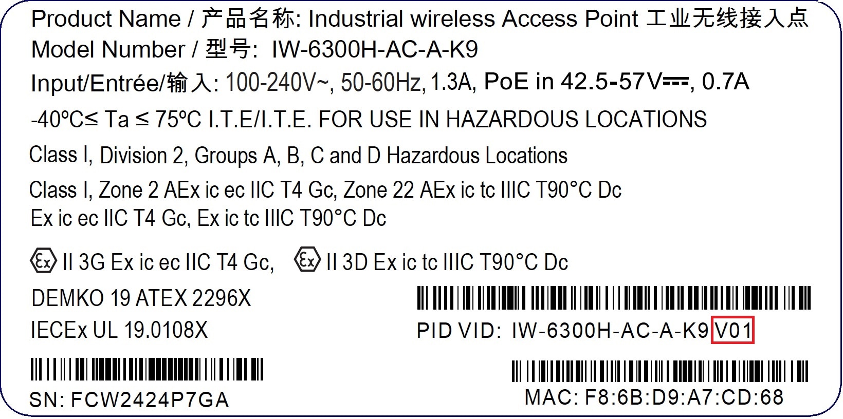
You can check the label on your device to find out whether your device is equipped with upgraded memory and NAND flash. On
the label, the VID field "1" means your device has 1024 MB DDR4 memory and 256 MB NAND flash. The VID field "2" means your
device has the new hardware of 2048 MB DDR4 memory and 1024 MB NAND flash. See the following figure for the location of VID
on the label. See the following figure for the location of VID on the access point label.
Figure 1. Location of VID on the Access Point Label
You can check VID by using the following Command Line Interfaces:
From the AP, execute the show inventory command
6300-DEMO#show inventory
NAME: IW6300, DESCR: Cisco Catalyst IW6300 Heavy Duty Series Access Points
PID: IW-6300H-DCW-B-K9, VID: V02, SN: ABC12345678
From IOS-XE controller, execute the show ap name <ap_name> inventory command.
eWLC#show ap name 6300-DEMO inventory
NAME: IW6300, DESCR: Cisco Catalyst IW6300 Heavy Duty Series Access Points
PID: IW-6300H-DCW-B-K9, VID: 02, SN: ABC12345678
From AireOS controller, execute the show ap inventory <ap_name> command.
(Cisco Controller) >show ap inventory 6300-DEMO
NAME: "IW6300", DESCR: "Cisco Catalyst IW6300 Heavy Duty Series Access Points"
PID: IW-6300H-DCW-B-K9, VID: V02,  SN: ABC12345678
You can also check VID from the controller GUI:
From IOS-XE controller GUI, go to Configuration → Wireless → Access Points → choose AP → Inventory tab.
From AireOS controller GUI, go to WIRELESS → ACCESS POINTS → choose AP → Inventory tab.
Note
When your AP is equipped with the new hardware and you want to downgrade the controller software version, the software image
will perform version check before the installation. Downgrade will be rejected if the target release does not support the
new hardware. The rejection log is only available on AP’s console, which may cause the administrator not able to figure out
the reason of AP failing to join the network (unsupported release) from wireless controller. The upgraded hardware is not
backward compatible, so it’s important to make sure the wireless controller is running the proper software version.
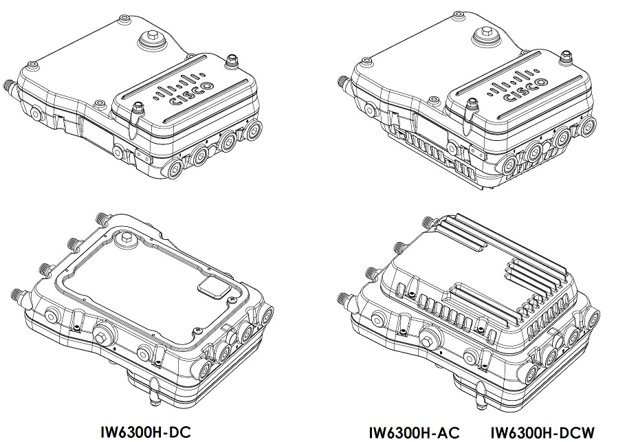
Hardware Models
Figure 2. IW-6300H Access Points
The model numbers (or part numbers) and configuration for the Cisco Catalyst IW6300 Heavy Duty Series Access Points are described
in the following table.
Table 1. Cisco Industrial Wireless 6300 Series Access Point Model Numbers and Descriptions
Model (or part number)
Configuration
IW-6300H-AC-x-K9
IP66 and IP67 rated, hazardous location certified, AC power version.
This model has 4 external antenna ports and contains a 2.4 GHz and 5 GHz radio with an option to configure in centralized,
Flexconnect, or mesh mode and supports AC power source.
IW-6300H-DCW-x–K9
IP66 and IP67 rated, hazardous location certified, DC wide range power version.
This model has 4 external antenna ports and contains a 2.4 GHz and 5 GHz radio with an option to configure in centralized,
Flexconnect, or mesh mode, and supports 10.8 VDC to 36 VDC power source.
Note
The marked DC input range is an absolute range. Do not apply tolerances.
IW-6300H-DC-x-K9
IP66 and IP67 rated, hazardous location certified, DC power version.
This model has 4 external antenna ports and contains a 2.4 GHz and 5 GHz radio with an option to configure in centralized,
Flexconnect, or mesh mode and supports 44 VDC to 57 VDC power source.
Note
The marked DC input range is an absolute range. Do not apply tolerances.
Note
The “-x” in the model number represents a regulatory domain for a specific country.
A detailed list of components supported by each access point model is shown in the following table.
Table 2. Components of Each Access Point Model
Product/PID
Power Input Option
Antenna Ports
Ethernet Ports
PoE Out Port
I/O Ports
IW-6300H-AC-x-K9
UPoE, PoE+, AC (100V to 240V)
Four Type N Connectors
One 100/1000Mbps SFP for WAN
One 100/1000Mbps RJ45 for WAN (UPoE or PoE+ in)
Two 100/1000Mbps RJ45 for LAN (802.3at or 802.3af out)
35.3W
Four 1/2” NPT Ports
IW-6300H-DCW-x–K9
UPoE, PoE+, DC (10.8V to 36V)
IW-6300H-DC-x-K9
UPoE, PoE+, DC (44V to 57V)
Note
For IW-6300H-DC-x-K9, when you use DC as input power option, if you want to output
802.3at type 2 PoE out power, DC input must >=51V. If you want to output 802.3af
(802.3at type 1) PoE out power, DC input must >=45V.
Note
When powered with PoE+ or UPoE, the PoE Out power is not available, The PoE-Out port data link can still be active.
Hardware Features
This section describes the hardware features of the IW-6300H access point models.
Note
The illustrations in this document show all available connections for the access point. Unused connections are capped with
a connector plug to ensure the dust/watertight integrity of the access point. See the "Working with the Access Cover" section
for further details.
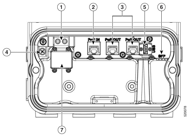
Internal Connectors
The following figure shows the IW-6300H Access Point Internal Connectors.
Figure 3. IW-6300H Access Point Internal Connectors
1
Power-IN (IW-6300H-DC-X-K9)
5
USB port
2
PoE In port
6
SFP port
3
PoE Out port
7
Terminal block location of IW-6300H-AC-X-K9 and IW-6300H-DCW-X-K9
4
Internal ground
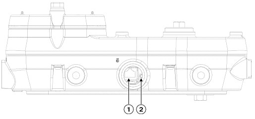
Console Port and Reset Button
The console port and reset button are under a covering M25 plug located on the side of the access point, as shown in the following
figure.
Figure 4. W-6300H Access Point Console Port and Reset Button
1
Console port
2
Reset button
Inspect the seal of the plug and properly tighten it at the time of installation, and also every time the plug is removed
and replaced. Tighten the plug to 5-6 lb-ft. If you do not tighten the plug properly, it will not meet IP66/67 criteria, and
may lead to water leaking into the unit.
Power Connector
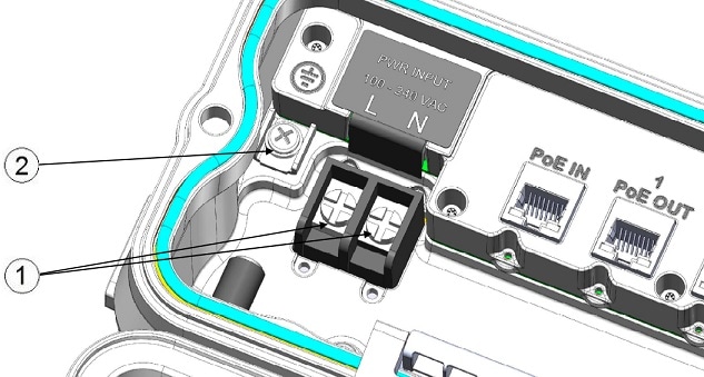
The following figure shows the power connector of access point model IW-6300H-AC-x-K9.
Figure 5. Power Connector of Access Point Model IW-6300H-AC-x–K9
1
AC Power-IN
2
Internal ground
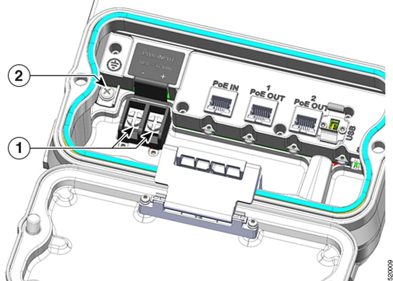
The following figure shows the power connector of access point model IW-6300H-DCW-x-K9.
Figure 6. Power Connector of Access Point Model IW-6300H-DCW-x–K9
1
DC Power-IN
2
Internal ground
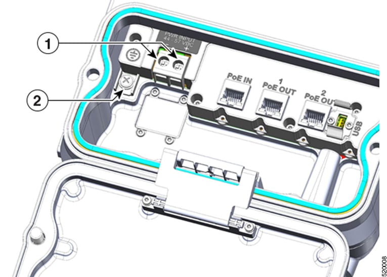
The following figure shows the power connector of access point model IW-6300H-DC-x-K9.
Figure 7. Power Connector of Access Point Model IW-6300H-DC-x–K9
1
DC Power-IN
2
Internal ground
Antenna Ports
The access point antenna N-type connectors are located on the top of each model (see the following figure). The supported
antennas can be directly attached to the access point or remotely located. When used in a Class 1, Zone 2, Division 2 hazardous
location, this equipment must be mounted with proper RF cables (if required) and electrical wiring methods that comply with
the governing electrical codes.
Note
Antenna caps must be installed when an antenna is not in use (maximum torque range: 6.2-9.7 in-lbs).
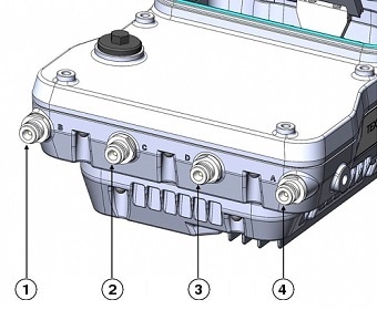
Figure 8. Antenna Ports of IW-6300H Access Points
1
Antenna port B - Type N connector Wi-Fi 2.4/5 GHz TX/RX
3
Antenna port D - Type N connector Wi-Fi 5 GHz TX/RX
2
Antenna port C - Type N connector Wi-Fi 5 GHz TX/RX
4
Antenna port A - Type N connector Wi-Fi 2.4/5 GHz TX/RX
The IW-6300H access point can be configured via software to support dual band or single band antennas. When configured for
dual band antennas, antenna ports A and B are used to support multiple input/output (MIMO) operation on both 2.4 and 5 GHz
radios. When using Cisco Aironet omnidirectional antennas with Type N male connectors, the antennas can be connected directly
to the access point. If the antennas are remotely located, an appropriate low loss RF cable should be used.
Note
Ensure that the antenna band mode is configured before the access point is installed.
When configured for single band antennas, antenna ports A and B support MIMO operation on the 2.4 GHz radio and antenna ports
C and D support MIMO operation on the 5 GHz radio. See the Cisco Catalyst IW6300 Heavy Duty Series Access Point Software Configuration Guide.
Use of four omnidirectional antennas attached directly to the Type N connectors is not recommended. To provide omnidirectional
coverage with both 2.4 and 5 GHz radios using directly attached antennas, it is recommended to configure the IW-6300H in dual
band mode, connect two dual band antennas such as AIR-ANT2547V-N, AIR-ANT2547V-N-HZ, or AIR-ANT2568VG-N to ports A and B,
and cap ports C and D.
The 2 GHz b/g/n radio operates in 2.4 GHz ISM band. It supports channels 1-11 in the US, 1-13 in Europe, and 1-13 in Japan.
It has 2 transmitters with a maximum total output power of 27 dBm for 802.11b/g/n operation. Output power is configurable
for 8 levels in 3 dB steps. It has two receivers that enable maximum-ratio combining (MRC).
The 5 GHz a/n radio operates in the UNII-1 band (5.15-5.25 GHz), UNII-2 band (5.25 - 5.35 GHz), UNII-2 Extended/ETSI band
(5.47 - 5.725 GHz), and the upper ISM band (5.725 - 5.850 GHz). It has two transmitters with a maximum total output power
of 27 dBm depending on the regulatory domain. Tx power settings will change depending on the regulatory domain. Output power
is configurable in 3 dB steps. Its two receivers enable maximum-ratio combining (MRC).
Power Sources
The Cisco Catalyst IW6300 Heavy Duty Series Access Points support the following power input
options:
Power over Ethernet
Power injector, AIR-PWRINJ-60RGD1= and AIR-PWRINJ-60RGD2=
Power over Ethernet Plus (PoE+) or Cisco Universal Power over Ethernet
(UPOE) switch
The marked DC input range is an absolute range. Do not apply tolerances.
Warning
Connect the unit only to DC power source that complies with the safety extra-low voltage (SELV) requirements in IEC 60950
based safety standards. Statement 1033
Power Injectors
The IW6300 series access points support the following power injectors:
AIR-PWRINJ-60RGD1=
AIR-PWRINJ-60RGD2=
Caution
Power injector AIR-PWRINJ-60RGDx= is not certified for installation within hazardous locations environments.
The access point supports two Ethernet uplink port (one PoE-In port and one SFP fiber port), and two PoE-Out ports. The access
point Ethernet uplink port uses an RJ-45 connector (with weatherproofing) to link the access point to the 10BASE-T, 100BASE-T
or 1000BASE-T network. The Ethernet cable is used to send and receive Ethernet data and to optionally supply inline power
from the power injector or a suitably powered switch port.
Tip
The access point senses the Ethernet and power signals and automatically switches internal circuitry to match the cable connections.
The Ethernet cable must be a shielded outdoor rated Category 5e (CAT5e) or better cable. The access point senses the Ethernet
and power signals and automatically switches internal circuitry to match the cable connections.
Fiber Option
Warning
Class 1 laser product. Statement 1008
The factory-orderable fiber option provides a fiber input and output capability. Fiber data is transmitted and received over
a single or dual-strand fiber cable, depending on the SFP, which is connected to the access point using these SFP modules:
SFP modules are not hot-swappable. Plug and unplug the SFP module, the AP will reboot.
Client data is passed to the network controller through the fiber connection via a fiber-capable switch or controller. Configuration
information can be found in the controller configuration guide of the switch or controller you are using.
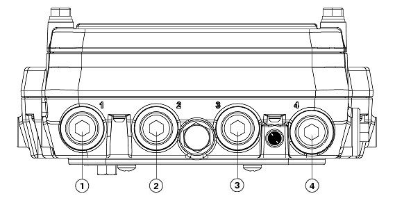
I/O Ports
The four 1/2-NPT I/O ports are located at the bottom of the access point. These ports are tapered pipe threads. It is recommended
that you use a 3/8” Allen wrench with 13-18" long wrench handle to remove the port plug.
Figure 9. 1/2-NPT I/O Ports
1
AC or DC input
3
PoE port
2
PoE port
4
Fiber port
Optional Hardware
Depending on the order configuration, the following optional access point hardware may be part of the shipment:
Cisco Aironet Antennas
Pole mount kits (IOT-ACCPMK=)
Band installation tool for pole mount kit (AIR-BAND-INST-TL=)
Power injector (AIR-PWRINJ-60RGDx=)
SFP module
Finding the Product Serial Number
The access point serial number is on the side of the access point. The access point serial number label contains the following
information:
Serial number
Access point MAC address, for example 68BDABF54600 (12 hexadecimal digits). It is located under the serial number.
You need your product serial number when requesting support from the Cisco Technical Assistance Center.
Related Documentation
To view all support information for the Cisco Catalyst IW6300 Heavy Duty Series Access Point, see:
To browse to the access point documentation, click Cisco Catalyst IW6300 Heavy Duty Series Access Point listed under “Outdoor and Industrial Wireless.” The documentation can be accessed from the Support box.
To browse to the Cisco Wireless LAN Controller documentation, click Standalone Controllers listed under “Wireless LAN Controllers.” The documentation can be accessed from the Support box.


 Feedback