Mounting on a Wall or a Pole
This section provides instructions for the physical installation of your access points. Personnel installing the access point must understand wireless access points and bridging techniques and grounding methods.
 Caution |
All installation methods for mounting an access point on any wall surface is subject to the acceptance of local jurisdiction. |
Installation Option
The Cisco Catalyst IW6300 Heavy Duty Series Access Points are installed using the pole mount installation kit (IOT-ACCPMK), which is used for pole or wall installations.
 Warning |
Only trained and qualified personnel should be allowed to install, replace, or service this equipment. Statement 1030 |
Warning |
Installation of the equipment must comply with local and national electrical codes. Statement 1074 |
Refer to these sections for installation details:
Access Point Mounting Orientation
Cisco Catalyst IW6300 Heavy Duty Series Access Points are only intended to be installed vertically with the antenna ports facing upwards. If you want the antennas to face down, you should use the Extender Bracket Kit (IOT-ACCPMK-LB=). Any other mounting orientation will compromise the IP66/67 and type 4X ingress ratings required for safety and hazardous locations compliance.
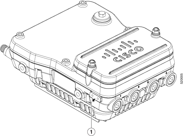
The access point is oriented with the system LED pointing down and the access cover facing out. This positioning allows the LEDs to be visible to someone on the ground below the access point, and the I/O interfaces are on the bottom to minimize moisture ingress in case ports are not adequately sealed.
 Note |
Omnidirectional antennas are vertically polarized and should be mounted vertically. |
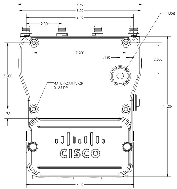
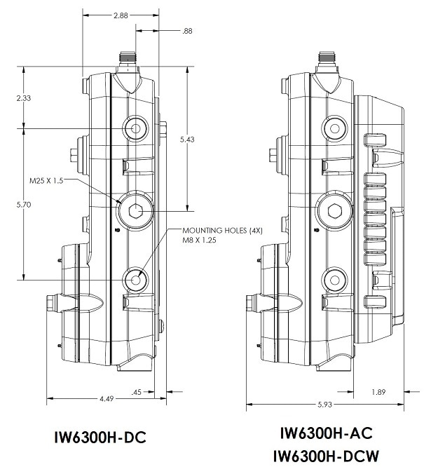
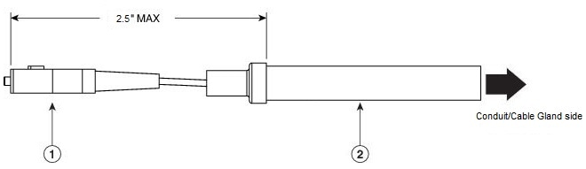
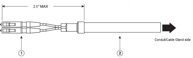
The following figures show the dimension of the access point:
Mounting the Access Point on a Wall
The optional pole mount kit contains a mounting bracket for wall mounting. You can use the mounting bracket as a template to mark the positions of the mounting holes for your installation. You then install the mounting plate, and attach the access point when you are ready. The following table lists the material that you will need to provide in addition to the pole mount kit.
|
Materials Required |
In Kit |
|---|---|
|
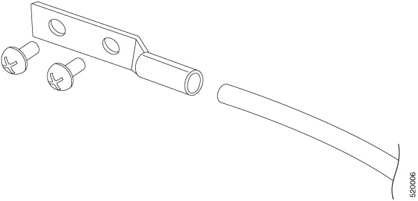
Ground lug and screws (provided with access point) |
Yes |
|
Crimping tool for ground lug |
No |
|
Four M8 or 5/16 in. (31 mm) screws |
No |
|
Four wall anchors (specified for wall material) |
No |
|
Drill bit for wall anchors |
No |
|
Electric drill and standard screwdriver |
No |
|
#6-AWG ground wire |
No |
|
Shielded outdoor-rated Ethernet (CAT5e or better) cable |
No |
|
Grounding block |
No |
|
Grounding rod |
No |
|
13-mm box-end wrench or socket set |
No |
Caution |
The mounting surface, attaching screws, and optional wall anchors must be able to support a 50-lb(22.7 kg) static weight. |
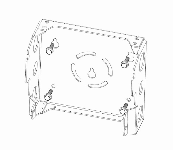
The mounting bracket can be used as a template to mark the screw hole locations. To mount the access point on a vertical wall, follow these instructions:
Procedure
|
Step 1 |
Use the mounting bracket as a template to mark four screw hole locations on your mounting surface. You can optionally use the individual mounting holes or the mounting slots. 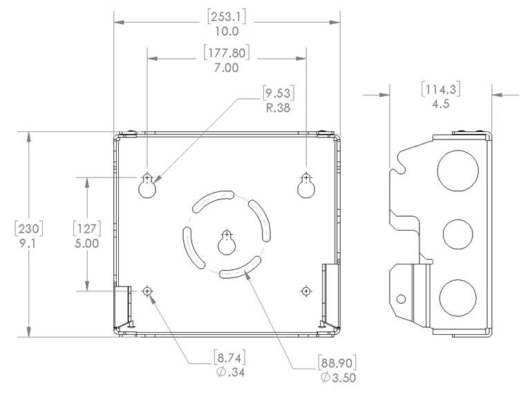
|
||||||||
|
Step 2 |
Use four customer-supplied screws and optional screw anchors to attach the mounting plate to the mounting surface.
|
||||||||
|
Step 3 |
Screw a M8 x16 bolt (with flat and lock washers) in the top support bolt hole on each side the access point. Do not screw the bolt all the way in; leave approximately a 0.25 inch (0.635 cm) space. |
||||||||
|
Step 4 |
Position the two bolts on the access point onto the hands-free attach points on each side of the mounting bracket. Ensure that the access point cover is facing out. Never leave the access point unattended until fully installed. 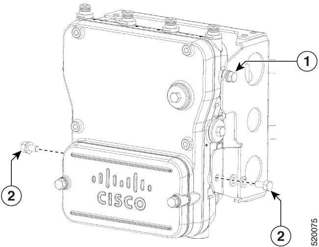
|
||||||||
|
Step 5 |
Screw a M8 x16 bolt (with flat and lock washers) into the second bolt hole on each side of the access point. |
||||||||
|
Step 6 |
Ensure that the front of the access point is vertical, and tighten the four bolts to 6 to 7 ft-lbs (8.1 to 9.5 Nm). |
||||||||
|
Step 7 |
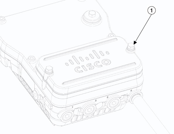
When using the Cisco Aironet Dual-Band Omnidirectional Antennas, connect them to the access point. Hand-tighten the antennas to the access point. |
||||||||
|
Step 8 |
Continue with Grounding the Access Point and Powering the Access Point. |
Wall Mounting with L Bracket
Cisco Catalyst IW6300 Heavy Duty Series Access Points are only intended to be installed vertically with the antenna ports facing upwards. If you want the antennas to face down, you should use the additional L Bracket (IOT-ACCPMK-LB) and the customer supplied RF cable is required.
Caution |
The mounting surface, attaching screws, and optional wall anchors must be able to support a 50-lb(22.7 kg) static weight. |
The mounting bracket can be used as a template to mark the screw hole locations. To mount the access point on a vertical wall, follow these instructions:
Procedure
|
Step 1 |
Use the mounting bracket as a template to mark four screw hole locations on your mounting surface. You can optionally use the individual mounting holes or the mounting slots.
|
||||||||||
|
Step 2 |
Use four customer-supplied screws and optional screw anchors to attach the mounting plate to the mounting surface.
|
||||||||||
|
Step 3 |
Use four bolts (with flat and lock washers) to install the L brackets to the mounting bracket as shown below. Tighten the bolts to 6 to 7 ft-lbs (8.1 to 9.5 Nm). 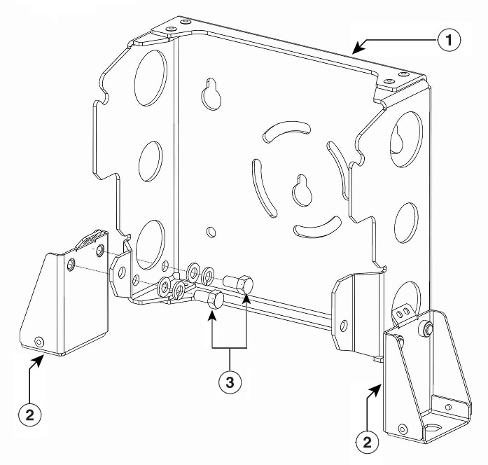
|
||||||||||
|
Step 4 |
Screw a M8 x16 bolt (with flat and lock washers) in the top support bolt hole on each side the access point. Do not screw the bolt all the way in; leave approximately a 0.25 inch (0.635 cm) space. 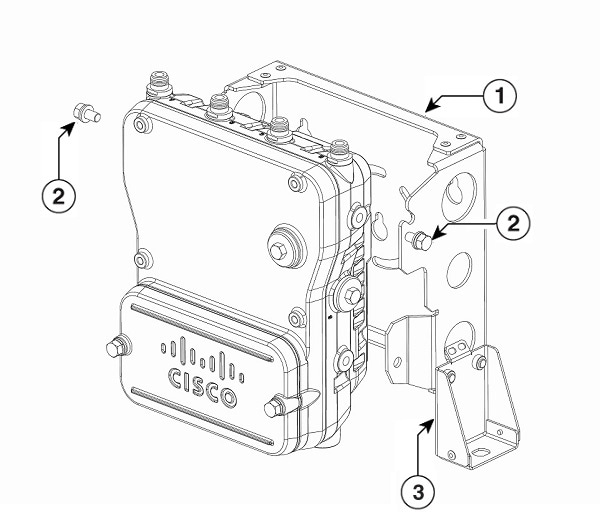
|
||||||||||
|
Step 5 |
Position the two bolts on the access point onto the hands-free attach points on each side of the mounting bracket. Ensure that the access point cover is facing out. Never leave the access point unattended until fully installed. |
||||||||||
|
Step 6 |
Screw a M8 x16 bolt (with flat and lock washers) into the second bolt hole on each side of the access point. 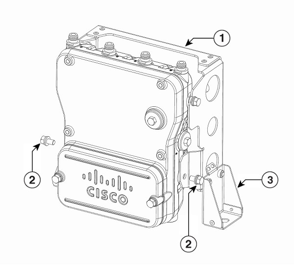
|
||||||||||
|
Step 7 |
Ensure that the front of the access point is vertical, and tighten the four bolts to 6 to 7 ft-lbs (8.1 to 9.5 Nm). |
||||||||||
|
Step 8 |
Insert the N-connector of the RF cable into the L-bracket and attach it with washer and nut (torque 12-15 in-lbs). Fix the RF cable to the L bracket with a zip tie cable as shown below.
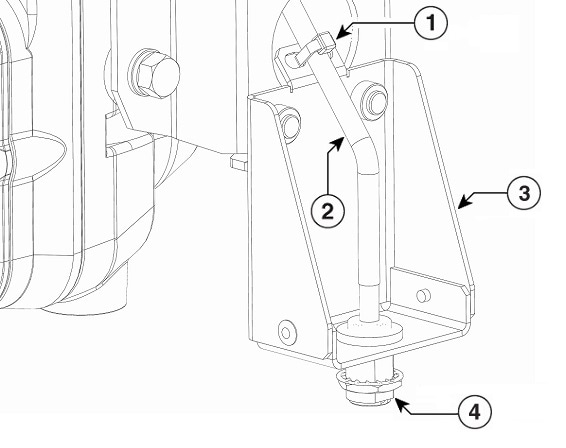
|
||||||||||
|
Step 9 |
Attach the right angle N-connector of the RF cable to the access point antenna port (torque 12-15 in-lbs). 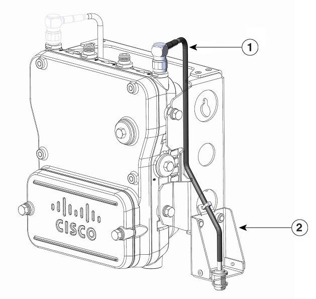
|
||||||||||
|
Step 10 |
Connect the antenna to the N-connector of the RF cable. Hand-tighten the antennas to the N-connector. 
|
||||||||||
|
Step 11 |
Continue with Grounding the Access Point and Powering the Access Point. |
Mounting the Access Point on a Pole
When installing an access point on a vertical pole, you should use the optional Cisco pole mount kit. The kit supports metal, wood, or fiberglass poles from 2 to 16 inches in diameter.
Assembling the Pole Clamp Bracket and the Mounting Bracket
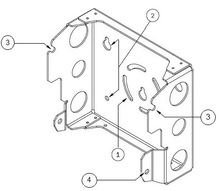
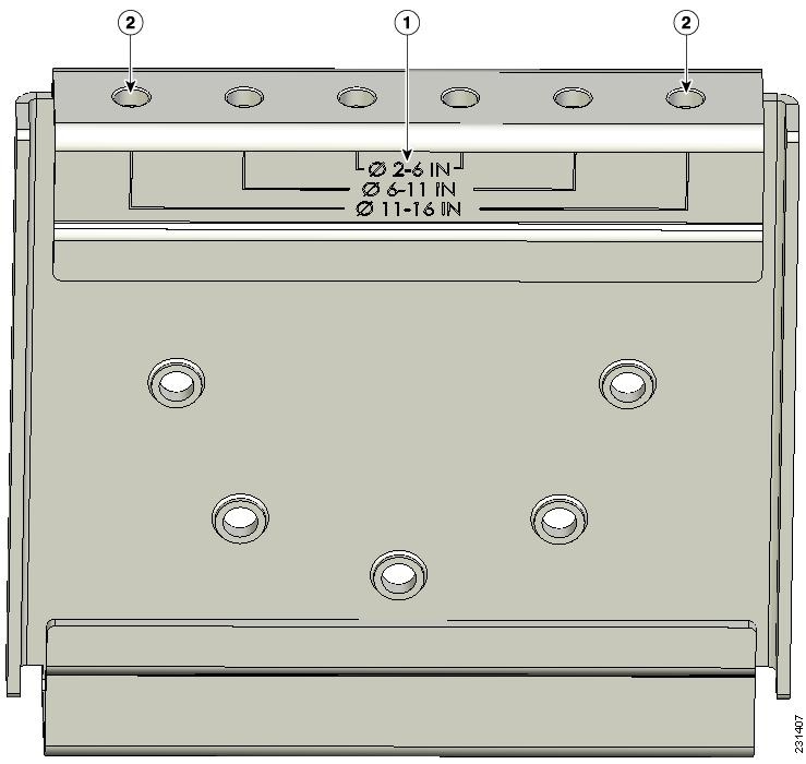
The pole mount kit contains several parts that you must assemble prior to mounting on a pole. First you need to assemble two strap brackets on the pole clamp bracket that are positioned for the pole diameter you are using to mount the access point. The following figure illustrates the pole diameter indicators and bolt holes on the pole clamp bracket.
|
1 |
Pole size indicators
|
2 |
Bolt holes for pole diameters (11 to 16 inches (27.94 cm to 40.64 cm) indicated) |
To assemble the pole clamp bracket, follow these steps:
Procedure
|
Step 1 |
Position the strap brackets on the pole clamp bracket for the pole diameter you are using and secure each strap bracket with two M8 x16 bolts (with lock washers). Tighten the bolts to 13 to 15 ft lbs (17.6 to 20.3 Nm). 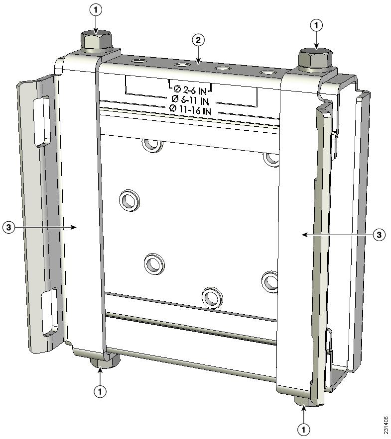
|
||||||||
|
Step 2 |
Screw the M8 nut onto the pole clamp bracket support bolt, and tighten just enough to prevent the bolt from falling off. |
||||||||
|
Step 3 |
Go to Pole Mounting. |
Pole Mounting
To mount your access point on a vertical pole, you need to install two metal bands around the pole to support the access point. This process requires extra tools and material not provided in the pole mount kit (see the following table).
|
Mounting Method |
Materials Required |
In Kit |
|---|---|---|
|
Vertical or streetlight pole |
Two 0.75-in (1.9 cm) stainless steel bands |
Yes |
|
Banding strap tool (BAND IT) (Cisco AIR-BAND-INST-TL=) |
No |
|
|
Ground lug (provided with access point) |
Yes |
|
|
Crimping tool for ground lug, Panduit CT-720 with CD-720-1 die (http://onlinecatalog.panduit.com) |
No |
|
|
#6 AWG ground wire |
No |
To mount the access point onto a vertical pole, follow these steps:
Procedure
|
Step 1 |
Select a mounting location on the pole to mount the access point. You can attach the access point to any pole from 2 to 16 inch (5.1 to 40.6 cm) in diameter. |
||||||||||
|
Step 2 |
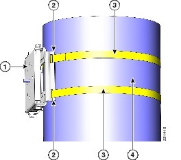
For poles larger than 3.5 inch (8.9 cm), mount the pole clamp bracket assembly to a pole using two metal straps. Following the instructions provided with the banding strap tool (BAND IT) (AIR-BAND-INST-TL=), loop each metal strap twice through the slots on the strap bracket.
|
||||||||||
|
Step 3 |
For pole diameters of 3.5 inch (8.9 cm) or less, mount the pole clamp bracket assembly to a pole using two metal straps looped through the space between the pole clamp bracket and the strap brackets to provide maximum holding strength for extreme environments. Following the instructions provided with the banding strap tool (BAND IT) (AIR-BAND-INST-TL=), loop each metal strap twice.
|
||||||||||
|
Step 4 |
Position the pole clamp bracket on the pole as needed before tightening the metal bands.
|
||||||||||
|
Step 5 |
Tighten the metal bands using the banding strap tool (BAND IT) (Cisco AIR-BAND-INST-TL=) by following the operating instructions in the box with the tool. Ensure that the metal bands are as tight as possible. |
||||||||||
|
Step 6 |
Place the mounting bracket onto the pole clamp bracket support bolt. |
||||||||||
|
Step 7 |
Install four M8 x16 bolts (with flat and lock washers) into the bolt holes. |
||||||||||
|
Step 8 |
Hand-tighten the bolts and the nut (do not overtighten). |
||||||||||
|
Step 9 |
Adjust the top edge of the mounting bracket until it is horizontal and tighten the bolts and the flange nut to 13 to 15 ft lbs (17.6 to 20.3 Nm). 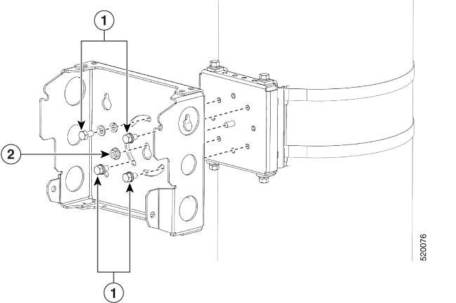
|
||||||||||
|
Step 10 |
Screw a M8 x16 bolt (with a flat or lock washer) in the top support bolt hole on each side the access point. Do not screw the bolt all the way in. Leave a gap of approximately 0.25 inch (0.635 cm). |
||||||||||
|
Step 11 |
Position the two bolts on the access point onto the hands-free attach point of the mounting bracket.
|
||||||||||
|
Step 12 |
Screw a M8 x16 bolt (with flat and lock washers) into the second bolt hole on each side of the access point. 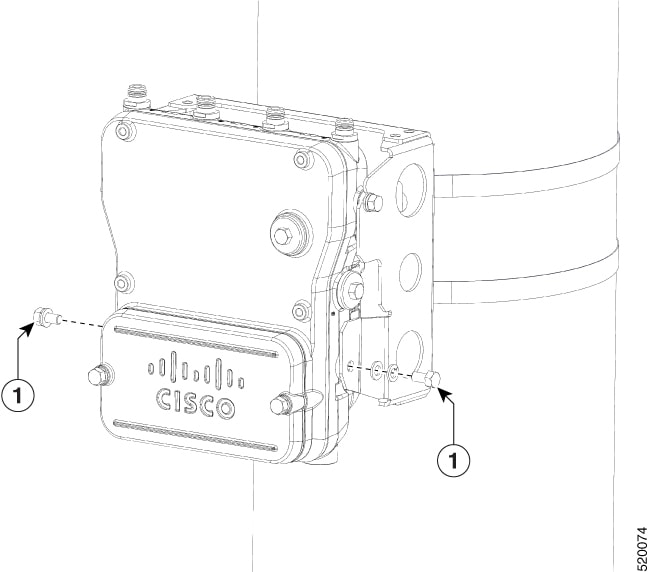
|
||||||||||
|
Step 13 |
Ensure that the front of the access point is vertical, and tighten the four bolts to 6 to 7 ft-lbs (8.1 to 9.5 Nm). 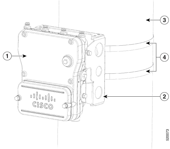
|
||||||||||
|
Step 14 |
When using the Cisco Aironet Dual-Band Omnidirectional Antennas, connect them to the access point. Hand-tighten the antennas to the access point. |
||||||||||
|
Step 15 |
Continue with Grounding the Access Point and Powering the Access Point. |
Pole Mounting with L Bracket
Cisco Catalyst IW6300 Heavy Duty Series Access Points are only intended to be installed vertically with the antenna ports facing upwards. If you want the antennas to face down, you should use the additional L Bracket (IOT-ACCPMK-LB) and the customer supplied RF cable is required.
To mount the access point onto a vertical pole, follow these steps:
Procedure
|
Step 1 |
Select a mounting location on the pole to mount the access point. You can attach the access point to any pole from 2 to 16 inch (5.1 to 40.6 cm) in diameter. |
||||||||||
|
Step 2 |
For poles larger than 3.5 inch (8.9 cm), mount the pole clamp bracket assembly to a pole using two metal straps. Following the instructions provided with the banding strap tool (BAND IT) (AIR-BAND-INST-TL=), loop each metal strap twice through the slots on the strap bracket.
|
||||||||||
|
Step 3 |
For pole diameters of 3.5 inch (8.9 cm) or less, mount the pole clamp bracket assembly to a pole using two metal straps looped through the space between the pole clamp bracket and the strap brackets to provide maximum holding strength for extreme environments. Following the instructions provided with the banding strap tool (BAND IT) (AIR-BAND-INST-TL=), loop each metal strap twice.
|
||||||||||
|
Step 4 |
Position the pole clamp bracket on the pole as needed before tightening the metal bands.
|
||||||||||
|
Step 5 |
Tighten the metal bands using the banding strap tool (BAND IT) (Cisco AIR-BAND-INST-TL=) by following the operating instructions in the box with the tool. Ensure that the metal bands are as tight as possible. |
||||||||||
|
Step 6 |
Place the mounting bracket onto the pole clamp bracket support bolt. |
||||||||||
|
Step 7 |
Install four M8 x16 bolts (with flat and lock washers) into the bolt holes. |
||||||||||
|
Step 8 |
Hand-tighten the bolts and the nut (do not overtighten). |
||||||||||
|
Step 9 |
Adjust the top edge of the mounting bracket until it is horizontal and tighten the bolts and the flange nut to 13 to 15 ft lbs (17.6 to 20.3 Nm).
|
||||||||||
|
Step 10 |
Use four bolts (with flat and lock washers) to install the L brackets to the mounting bracket as shown below. Tighten the bolts to 6 to 7 ft-lbs (8.1 to 9.5 Nm).
|
||||||||||
|
Step 11 |
Screw a M8 x16 bolt (with a flat or lock washer) in the top support bolt hole on each side the access point. Do not screw the bolt all the way in. Leave a gap of approximately 0.25 inch (0.635 cm). |
||||||||||
|
Step 12 |
Position the two bolts on the access point onto the hands-free attach point of the mounting bracket.
|
||||||||||
|
Step 13 |
Screw a M8 x16 bolt (with flat and lock washers) into the second bolt hole on each side of the access point.
|
||||||||||
|
Step 14 |
Ensure that the front of the access point is vertical, and tighten the four bolts to 6 to 7 ft-lbs (8.1 to 9.5 Nm).
|
||||||||||
|
Step 15 |
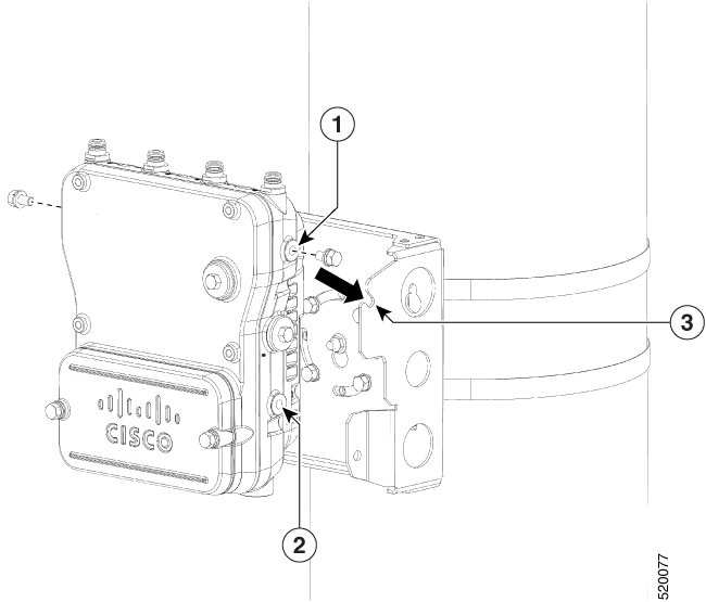
Insert the N-connector of the RF cable into the L-bracket and attach it with washer and nut (torque 12-15 in-lbs). Fix the RF cable to the L bracket with a zip tie cable as shown below.
|
||||||||||
|
Step 16 |
Attach the right angle N-connector of the RF cable to the access point antenna port (torque 12-15 in-lbs).
|
||||||||||
|
Step 17 |
Connect the antenna to the N-connector of the RF cable. Hand-tighten the antennas to the N-connector.
|
||||||||||
|
Step 18 |
Continue with Grounding the Access Point and Powering the Access Point. |

 Feedback