The documentation set for this product strives to use bias-free language. For the purposes of this documentation set, bias-free is defined as language that does not imply discrimination based on age, disability, gender, racial identity, ethnic identity, sexual orientation, socioeconomic status, and intersectionality. Exceptions may be present in the documentation due to language that is hardcoded in the user interfaces of the product software, language used based on RFP documentation, or language that is used by a referenced third-party product. Learn more about how Cisco is using Inclusive Language.
captures and forwards packets on a specified channel to a remote packet analyzer
allows monitoring and recording of network activity
detects network problems, and
receives encapsulated 802.11 traffic at the packet analyzer.
Key characteristics
Network packet capture: The sniffer captures live packets and forwards them to a packet analyzer for inspection.
Protocol support: It works with protocols like Airopeek for encapsulation and transfer via specified UDP ports.
Management integration: Sniffers can be configured through AP modes and require resetting to revert to normal operations.
Recommendations
Use Clear in AP mode to return the AP back to client-serving mode, such as local or FlexConnect depending on the remote site tag configuration.
Do not use the AP command to change the CAPWAP mode.
XOR radio roles
A XOR radio is a configuration that
allows the XOR radio to function in multiple modes via a single radio interface
eliminates the need to switch the entire AP into a separate mode, and
is implemented at the radio level and referred to as "roles."
XOR radio roles facilitate the operation of wireless network radios. This is specifically applicable to models like the Cisco
Catalyst 2800, 3800, 4800, and 9100 series AP models. The Sniffer role, supported from the current release onwards, is offered
alongside the Client Serving and Monitor roles.
Feature history for sniffer mode
Table 1. Feature history
Release
Feature
Feature information
Cisco IOS XE 17.8.1
XOR Radio Role Sniffer Support on the Access Point
The XOR radio in APs like Cisco 2800, 3800, 4800, and the 9100 series AP models support sniffer role in single radio interface.
Supporting reference information
The radio role is supported in both Local and FlexConnect modes.
Essential hardware and software for sniffer setup
You will need the following hardware and software to perform sniffing:
A dedicated access point: An AP configured as a sniffer cannot simultaneously provide wireless access service on the network.
To avoid disrupting coverage, use an access point that is not part of your existing wireless network.
A remote monitoring device: A computer capable of running the analyzer software.
Software, supporting files, plug-ins, or adapters: Your analyzer software may require specialized files to function effectively.
Restrictions on sniffer
These are the supported third-party network analyzer software applications:
Wildpackets Omnipeek or Airopeek
AirMagnet Enterprise Analyzer
Wireshark
The latest version of Wireshark can decode the packets by going to the Analyze mode. Select decode as, and switch UDP5555 to decode as PEEKREMOTE.
You cannot use Sniffer mode when the controller L3 interface is the Wireless Management Interface (WMI).
When an AP or a radio operates in the sniffer mode, irrespective of its current channel width settings, the AP sniffs or captures
only on the primary channel.
Note
As both Cisco Catalyst 9166I and 9166D APs have XOR radios, a Board Device File (BDF) has to be loaded to initialize radio
2 for the radios of these APs to work as expected. While the BDF is being loaded and for the file to be loaded correctly,
the firmware has to be made non-operational and radios have to be reset. This operation of radio reset due to firmware being
non-operational for the purposes of loading the BDFs is deliberate and is an expected behavior. This operation can be observed
in both the controller and Cisco Catalyst Center. We recommend that you ignore the core dump that is generated due to this
deliberate operation.
How to Configure Sniffer
Configure an access point as sniffer (GUI)
This task guides you through configuring an access point to sniffer mode using the GUI, allowing the access point to capture
wireless traffic in a specified location.
Procedure
Step 1
Choose Configuration > Wireless > Access Points.
Step 2
On the General tab, update the name of the AP. The AP name can be ASCII characters from 33 to 126, without leading and trailing spaces.
Step 3
Specify the physical location where the AP is present.
Step 4
Choose the Admin Status as Enabled if the AP is to be in enabled state.
Step 5
Choose the mode for the AP as Sniffer.
Step 6
In the Tags section, specify the appropriate policy, site, and RF tags that you created on the Configuration > Tags & Profiles > Tags page.
Note
If the AP is in sniffer mode, you do not want to assign any tag.
Step 7
Click Update & Apply to Device.
Step 8
Choose the mode for the AP as Clear to return the AP back to the client-serving mode depending on the remote site tag configuration.
Note
Changing the AP mode to Sniffer will set all radios to manual mode. A warning will prompt you to revert the radio submode
to AUTO if required when changing modes.
The AP is configured in sniffer mode, ready for capturing wireless traffic at the specified location.
Configure an access point as sniffer (CLI)
Set an AP to sniffer mode so that it can monitor network traffic.
Procedure
Step 1
Enable privileged EXEC mode.
Example:
Device>enable
Step 2
Configure the AP to function as a sniffer.
Example:
Device# ap name access1 mode sniffer
Where,
ap-name is the name of the Cisco lightweight access point.
Use the no form of this command to disable the access point as a sniffer.
The AP operates in sniffer mode, capturing and monitoring network traffic.
Enable or Disable sniffing on the access point (GUI)
This task guides you through enabling or disabling sniffing mode on an AP using the GUI.
Before you begin
You must change the AP mode to sniffer mode.
Procedure
Step 1
Choose Configuration > Wireless > Access Points.
Step 2
On the Access Points page, click the AP name from the
6 GHz, 5 GHz, or 2.4 GHz list.
Step 3
In the Role Assignment section, select the Assignment Method as Sniffer.
Step 4
In the Sniffer Channel Assignment section, check the Sniffer Channel Assignment checkbox to enable.
Uncheck the checkbox to disable sniffing on the access point.
Step 5
From the Sniff Channel drop-down list, select the channel.
Note
By default, the Sniff Channel is set to 36 for the 5 GHz and 1 for the 2.4 GHz.
Step 6
Enter the IP address into the Sniffer IP field.
To validate the IP address, click Update & Apply to Device. If the IP address is valid, the Sniffer IP Status displays Valid.
Step 7
In the RF Channel Assignment section, configure these items:
Note
The section will be enabled for editing only if the Assignment Method is set to Custom.
From the RF Channel Width drop-down list, select the channel width.
From the Assignment Method drop-down list, choose the type of assignment.
Note
If you choose Custom, you must select a channel width and specify an RF channel number to the access point radio.
Step 8
Click Update & Apply to Device.
The AP is configured to either operate in sniffing mode or have sniffing mode disabled based on your choice.
Enable or Disable sniffing on the access point (CLI)
This task enables you to manage the sniffing feature on an AP using CLI commands, specifically to enable or disable it as
necessary.
Procedure
Step 1
Enable privileged EXEC mode.
Example:
Device> enable
Step 2
Enable sniffing on the AP.
Example:
Device# <userinput>ap name access1 sniff dot11b 1 9.9.48.5</userinput>
channel is the valid channel to be sniffed. For 802.11a, the range is 36 to 165. For 802.11b, the range is 1 to 14. For dot11 6 GHz,
the range is between 1 and 233.
server-ip is the IP address of the machine running network monitoring software.
Step 3
Disable sniffing on the AP.
Example:
Device#<userinput>ap name access1 no sniff dot116ghz</userinput>
The sniffing feature is enabled or disabled on the AP based on the commands executed. Ensure that you verify the current status
of the configuration.
Configure XOR radio role sniffer support on the access point (CLI)
Enable the XOR radio on a AP to operate as a sniffer by manually configuring its role and settings through CLI.
Procedure
Step 1
Enable privileged EXEC mode. Enter your password, if prompted.
Example:
Device> enable
Step 2
Shut down the XOR radio.
Example:
Device# ap name AP687D.B45C.189C dot11 dual-band shutdown
Step 3
Convert the XOR radio role to manual.
Example:
Device# ap name ap-name dot11 dual-band role manual client-serving
Step 4
Configure XOR radio to manually operate in a specific band.
Example:
Device# ap name AP687D.B45C.189C dot11 dual-band band 5ghz
Step 5
Enable XOR radio role Sniffer support on AP from the controller.
Example:
Device# ap name AP687D.B45C.189C dot11 dual-band radio role manual sniffer channel 100 ip 9.4.197.85
Where,
ap-name is the name of the Cisco lightweight access point.
channel-number is the channel number.
Step 6
Activate the XOR radio.
Example:
Device# ap name AP687D.B45C.189C no dot11 dual-band shutdown
Step 7
Return to privileged EXEC mode.
Example:
Device# end
Note
When configuring the radio to work as a Sniffer in the 5 GHz band, make sure to change the band of the radio manually.
XOR radio on the AP is configured to operate as a sniffer, allowing you to monitor and analyze wireless traffic on a specified
channel.
Verify sniffer configurations
Use these commands to verify sniffer configurations on AP and gather specifics regarding the sniffing setup in multiple bands
and slots.
Table 2. Commands for verifying sniffer configurations
Commands
Description
show ap nameap-nameconfig dot11 {24ghz | 5ghz | 6ghz | dual-band}
Displays the sniffing details.
show ap nameap-nameconfig slotslot-ID
Displays the sniffing configuration details.
slot-ID ranges from 0 to 3. All access points have slot 0 and 1.
Verify XOR radio role sniffer configuration
To verify the XOR radio role sniffer configuration for a given AP, use this command:
Device# show ap name AP687D.B45C.189C config slot 0
Sniffing : Enabled
Sniff Channel : 6
Sniffer IP : 9.4.197.85
Sniffer IP Status : Valid
ATF Mode : Disable
ATE Optimization : N/A
AP Submode : Not Configured
Remote AP Debug : Disabled
Logging Trap Severity Level : information
Software Version : 17.9.0.18
Boot Version : 1.1.2.4
Mini IOS Version : 0.0.0.0
Stats Reporting Period : 60
primary_discovery_timer : 120
LED State : Enabled
LED Flash State : Enabled
LED Flash Timer : 0
PoE Pre-Standard Switch : Disabled
PoE Power Injector MAC Address : Disabled
Power Type/Mode : PoE/Full Power
Number of Slots : 4
AP Model : C9136I-B
IOS Version : 17.9.0.18
Reset Button : Disabled
AP Serial Number : FOC25322JJZ
AP Certificate Type : Manufacturer Installed Certificate
AP Certificate Expiry-time : 08/09/2099 20:58:26
AP Certificate issuer common-name : High Assurance SUDI CA
AP Certificate Policy : Default
AP CAPWAP-DTLS LSC Status
Certificate status : Not Available
AP 802.1x LSC Status
Certificate status : Not Available
AP User Name : admin
AP 802.1X User Mode : Global
AP 802.1X User Name : Not Configured
Cisco AP System Logging Host : 255.255.255.255
AP Up Time : 4 hours 20 minutes 55 seconds
AP CAPWAP Up Time : 4 hours 16 minutes 17 seconds
Join Date and Time : 01/19/2022 03:06:12
Attributes for Slot 0
Radio Type : 802.11ax - 2.4 GHz
Radio Mode : Sniffer
Radio Role : Sniffer
Maximum client allowed : 400
Radio Role Op : Manual
Radio SubType : Main
Administrative State : Enabled
Operation State : Up
Examples for sniffer configurations and monitoring
This example shows how to configure an AP as sniffer:
Device# ap name access1 mode sniffer
This example shows how to enable sniffing on the AP:
Device# ap name sniffer dot11 5ghz sniff 44 1.1.1.1
This example shows how to disable sniffing on the AP:
Device# ap name access1 no sniff dot11b
This example shows how to display the sniffing configuration details:
Device# show ap name access1 config dot11 24ghz
Device# show ap name access1 config slot 0
Monitor mode
A monitor mode is a wireless operational mode that
optimizes the monitoring of 802.11b/g/x network channels
enhances location calculation for RFID tags, and
allows limited channel scanning.
Key features of Monitor Mode
Channel optimization: Optimize the monitoring by limiting the scanning to 2.4-GHz channels, such as 1, 6, and 11.
RFID tag tracking: Enable precise tag-tracking by focusing on specific operational frequencies.
AP Mode Transition
You can move an AP to a particular mode (sensor mode to local mode or Flexconnect mode) using the site tag with the corresponding
mode. If the AP is not tagged to any mode, it uses the default site tag mode.
Tip
To optimize operational efficiency, ensure that the AP is tagged correctly.
Returning AP to Client-Serving Mode
You must use clear in AP mode to return the AP back to client-serving mode, for example the local mode or FlexConnect mode
depending on the remote site tag configuration.
Enable monitor mode (GUI)
Switch the AP to monitor mode using the GUI.
Use these steps to enable monitor mode for the AP:
Procedure
Step 1
Choose Configuration > Wireless > Access Points.
Step 2
In the Access Points page, expand the All Access Points section and click the name of the AP to edit.
Step 3
In the Edit AP page, click the General tab and from the AP Mode drop-down list, choose Monitor.
Step 4
Click Update & Apply to Device.
Step 5
Choose the mode for the AP as clear to return the AP back to the client-serving mode depending on the remote site tag configuration.
The AP is now in monitor mode and can observe wireless traffic without serving clients.
Enable Monitor Mode (CLI)
Enable and configure monitor mode on APs, ensuring they scan specific channels for network monitoring.
Follow these steps to enable monitor mode:
Procedure
Step 1
Enable monitor mode for the AP.
Example:
Device# ap name 3602a mode monitor
Step 2
Configure the AP to scan only the Dynamic Channel Assignment (DCA) channels supported by its country of operation.
Example:
Device# ap name 3602a monitor tracking-opt
Step 3
Choose up to four specific 802.11b channels to be scanned by the AP.
Example:
Device# ap name 3602a monitor dot11b 1 2 3 4
In the United States, you can assign any value from 1 to 11 (inclusive) to the channel variable. Other countries support additional
channels. You must assign at least one channel.
Step 4
Configure the 802.11 6-Ghz radio role manual monitor.
Example:
Device# ap name cisco-ap dot11 6ghz slot 3 radio role manual monitor
slot 3 radio role manual monitor
Step 5
View configuration and statistics of 802.11a or 802.11b or 6-GHz channel assignment.
Example:
Device# show ap dot11 5ghz channel
Step 6
View configuration and statistics summary of 6 GHz band APs.
Example:
Device# show ap dot11 6ghz summary
The APs are set to monitor mode, scanning the specified channels and enabling effective network monitoring and channel assessment.
Management Mode Migration for Cisco Catalyst Wireless 916X Series Access Points
A management mode is a configuration setting in networking devices that:
determines how a device connects to the network
controls the operating mode of access points, and
allows flexibility through configurable options such as cloud-based or on-premises management.
Cisco Catalyst Wireless 916x APs support both 6 GHz and 5 GHz bands through dual-band slot 3 radios.
Feature History for management mode migration in Cisco catalyst wireless 916X access points
Table 3. Feature history
Release
Feature
Feature information
Cisco IOS XE Cupertino 17.9.1
Management Mode Migration in Cisco Catalyst Wireless 916X Series Access Points
This feature allows you to convert the AP mode between DNA Management mode and Meraki Management mode, depending on your requirements.
Note
The document explains the conversion from DNA Management mode to Meraki Management mode and not vice versa.
Management modes
DNA Management mode: Allows the access point to utilize Cisco's Digital Network Architecture for advanced network capabilities
and management.
Meraki Management mode: Enables integration and management through Cisco's Meraki Cloud.
Note
The management mode migration configuration is specifically oriented for transitioning from DNA Management mode to Meraki
Management mode and not the reverse. Migration can be configured through CLI in privileged EXEC mode at the AP level and from
the controller GUI.
Regulatory domain
For regulatory domain support, Cisco Catalyst 916x Series APs (CW916x) support Rest of the World (RoW) and various fixed domains.
The Cisco Catalyst 916x Series APs support the following domains:
-B
-E
-A
-Z
-Q
-I
-R
These domains define the specific regions or countries where the Cisco Catalyst 916x can operate in compliance with local
regulations.
AP join flow functionality
During the AP join flow, the AP passes the regulatory domain details and configured country to the controller. The controller
assigns or validates the right country of operation. After validation based on the decision tree, the controller informs the
AP of the country with which it should be configured.
Recommendation to configure AP regulatory domain
AP configured with non-RoW regulatory domain
Case 1: AP does not report a country as part of the join procedure.
In the non-RoW regulatory domain, when an AP does not report a country as part of the join procedure, the process occurs:
AP profile has a country configured.
If the country configured in the AP profile is present in the global country list, and is valid as per the AP regulatory domain,
the country that is configured in the AP profile is assigned to the AP. Radios become operational as per the country or regulatory
domain support.
If the country configured in the AP profile is not present in the global country list, and is not valid as per the AP regulatory
domain, the AP is disconnected.
AP profile does not have a country configured. Find a valid country from the global country list (the first match), as per
the AP regulatory domain.
If the country is found, the country is assigned to the AP and the radios become operational as per the country or regulatory
domain support.
If the country is not found, the AP is disconnected.
Case 2: AP reports a country as part of the join procedure.
In the non-RoW regulatory domain, when an AP reports a country as part of the join procedure, the following takes place:
The AP profile has a country configured.
If the country configured in the AP profile is present in the global country list, and it is valid as per the AP regulatory
domain, the country that is configured in the AP profile is assigned to the AP. Radios become operational as per the country
or regulatory domain support.
If the country configured in the AP profile is not present in the global country list, and is not valid as per the AP regulatory
domain, check the global country list to confirm the country's presence. If it is present in the global list, the AP retains
the previous country configuration and the radios are not operational with the country misconfiguration flag set. If the country
is not located in the global list, the AP is disconnected.
The AP profile does not have a country configured.
If the country reported by the AP is found in the global country list, and is valid as per the AP regulatory domain, the country
is assigned to the AP and the radios become operational as per the country or regulatory domain support.
If the country is not present in the list, search for the first country match from the global list. If the country is found,
the country is assigned to the AP and the radios become operational. If the country is not found, the AP is disconnected.
In the non-RoW regulatory domain, when an AP does not report a country as part of the join procedure, the following takes
place:
AP profile has a country configured.
If the country configured in the AP profile is present in the global country list, and is valid as per the AP regulatory domain,
the country that is configured in the AP profile is assigned to the AP. Radios become operational as per the country or regulatory
domain support.
If the country configured the AP profile is not present in the global country list, and is not valid as per the AP regulatory
domain, the AP is disconnected.
AP profile does not have a country configured. Find a valid country from the global country list (the first match), as per
the AP regulatory domain.
If the country is found, the country is assigned to the AP and the radios become operational as per the country or regulatory
domain support.
If the country is not found, the AP is disconnected.
AP configured with RoW regulatory domain
Case 1: The AP does not report a country as part of the join procedure.
In the RoW regulatory domain, when an AP does not report a country as part of the join procedure, this process occurs:
The AP profile has a country configured.
If the country configured in the AP profile is present in the global country list, and is valid as per the AP regulatory domain,
the country configured in the AP profile is assigned to the AP. Radios become operational as per the country or regulatory
domain support.
If the country configured in the AP profile is not present in the global country list, and is not valid as per the AP regulatory
domain, country is not assigned to the AP and radios are not operational, and the country misconfiguration flag is set.
If the AP profile does not have a country configured, the country is not assigned to the AP and radios are not operational,
and the country misconfiguration flag is set.
Case 2: The AP reports a country as part of the join procedure.
In the RoW regulatory domain, when an AP reports a country as part of the join procedure, the following takes place:
The AP profile has a country configured.
If the country configured in the AP profile is present in the global country list, and it is valid as per the AP regulatory
domain, the country that is configured in the AP profile is assigned to the AP. Radios become operational as per the country
or regulatory domain support.
If the country configured in the AP profile is not present in the global country list, and is not valid as per the AP regulatory
domain, the AP retains the previous country configuration and the radios are not operational with the country misconfiguration
flag set.
The AP retains the previous country configuration and the radios are not operational with the country misconfiguration flag
set.
Configure management mode migration (GUI)
Use the GUI to transition APs from DNA management mode to Meraki management mode. This improves network management efficiency.
Before you begin
You must configure the country code on the AP profile. To configure the country code, navigate to Configuration > Tags & Profiles > AP Join page. Click an AP profile to edit. In the General tab, select the country code from the drop-down list.
Use these steps to migrate the management mode using the GUI:
Procedure
Step 1
Choose Configuration > Wireless > Migrate to Meraki Management Mode.
Step 2
Select the APs you need by checking the boxes next to them from the displayed list.
The Migrate to Meraki Management Mode button is enabled.
Step 3
Click Migrate to Meraki Management Mode button to perform a validation check on the selected APs. If the validation check is successful, the Next button is enabled.
Step 4
Click Next to start the process.
Step 5
On the Confirm Management Mode Migration window, perform these actions:
Select the Agree and continue check box.
Click Yes to confirm.
The Management Mode Migration Successful section displays the APs that were migrated to the Meraki management mode. The Management Mode Migration Failed section displays the APs that were retained in DNA management mode.
Step 6
Click Restart Workflow to restart the workflow for APs that did not migrate from DNA management mode to Meraki management mode.
APs migrate to Meraki management mode. APs that fail to migrate remain in DNA management mode, allowing for further troubleshooting
or attempts.
Export meraki management mode-migrated APs (GUI)
Export the list of Meraki management mode-migrated APs to ensure information is available for further use, or integration
into other tools.
You can export the details about the Meraki management mode-migrated APs either from the Change to Meraki Persona tab after the workflow is completed or from the Previously changed APs tab.
Use these steps to export Meraki management mode-migrated APs:
Procedure
Command or Action
Purpose
Step 1
Choose Configuration > Wireless > Migrate to Meraki Management Mode.
Step 2
Click Export to export the list of APs.
Step 3
Select whether you want to export only the current page or all pages. Click Yes to continue.
Step 4
On the Export window, select the export method. The available options are:
Serial Number
JSON
Export to Meraki Dashboard
Note
We recommend the Export to Meraki Dashboard option as you can directly export the migrated APs information into the Meraki
Dashboard.
Step 5
Click Copy to copy the migrated APs. Click Download and save the file location.
Successfully exported migrated APs ensures that the data is readily available for review, storage, or integration, enhancing
operational efficiency.
Configure the access point management mode (CLI)
Change the management mode of an AP to Meraki using CLI.
Before you begin
Ensure that the AP is compatible with Meraki to run any of the EXEC commands. To verify, use the show ap management-mode meraki capability summary command.
Note
If the country code is misconfigured, the change of management mode will not be allowed for any of the EXEC commands, except
the force command.
If the regulatory domain is misconfigured for any slot, the change of management mode is not allowed for any of the EXEC commands,
except the force command.
Procedure
Step 1
Enable privileged EXEC mode.
Example:
Device# enable
Enter the password, if prompted.
Step 2
Change the AP management mode to Meraki.
Example:
Device# ap name <i>Cisco-AP-name</i> management-mode meraki
Device# ap name Cisco-AP-name management-mode meraki force
Device# ap name Cisco-AP-name management-mode meraki noprompt
Device# ap name Cisco-AP-name management-mode meraki force noprompt
Here, force skips the validations at the controller and attempts Meraki management mode change at the AP.
noprompt skips the user prompt for attempting AP management mode change.
Step 3
(Optional) Clear the Meraki AP-related data.
Example:
Device# clear ap meraki stats
The AP is configured to the Meraki management mode.
Verify the management mode migration details
To view the summary of the Meraki-capable AP information, run this command:
Device# show ap management-mode meraki capability summary
AP Name AP Model Radio MAC MAC Address AP Serial Number Meraki Serial Number
-----------------------------------------------------------------------------------------------------------------------------------
APXXXD.BXXX.1XXX CW9162I 6XXd.bXXe.eXX0 6XXd.bXXe.eXX0 FOCXXXXXB90 FOCXXXXXB90
To view the failure summary of the AP along with the migration attempt timestamp, run this command:
Device# show ap management-mode meraki failure summary
AP Name AP Model Radio MAC MAC Address Conversion Attempt AP Serial Number Meraki Serial Number Reason Code
----------------------------------------------------------------------------------------------------------------------------------------------------------------------------------
APXXXD.BXXC.1 CW9162I 6XXd.bXXe.eXX0 6XXd.bXXe.eXX0 03/03/2022 17:17:42 IST FOCXXXXXB90 FOCXXXXXB90 Regulatory domain not set
To view the successful Meraki management mode migration attempts of all the APs, run this command:
Device# show ap management-mode meraki change summary
AP Name AP Model Radio MAC MAC Address Conversion Timestamp AP Serial Number Meraki Serial Number
---------------------------------------------------------------------------------------------------------------------------------------------------------------------
APXXXX.3XXX.EXXX CW9166I-B 1XXX.2XXX.1100 ccXX.3XXX.eXX0 05/02/2022 07:48:56 CST KWC2XXXXX5G Q5XX-4XXX-K7XX
FlexConnect Authentication
A FlexConnect authentication mode is a WLAN operating state that
defines how a FlexConnect AP handles client authentication and data switching
changes its behavior based on connection status to the controller, and
enables resilient client connectivity during both connected and standalone operation.
Locally switched: : The AP forwards a client’s data traffic directly onto the local LAN or VLAN at the site, instead of tunneling that traffic
through the controller.
Centrally switched: The AP forwards the client’s data traffic to the controller, depending on the WLAN configuration.
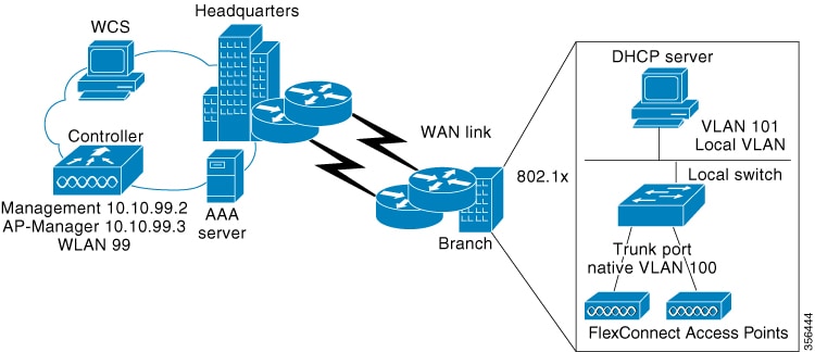
FlexConnect is a wireless solution for branch office and remote office deployments. It enables customers to configure and
control access points (AP) in a branch or remote office from the corporate office through a wide area network (WAN) link without
deploying a controller in each office. The FlexConnect access points can also switch client data traffic locally and perform
client authentication locally when their connection to the controller is lost. When they are connected to the controller,
they can also send traffic back to the controller. FlexConnect access points support multiple SSIDs. In the connected mode,
the FlexConnect access point can also perform local authentication.
Figure 1. FlexConnect Deployment
The controller software has a more robust fault tolerance methodology to FlexConnect access points. Whenever a FlexConnect AP disassociates
from controller , it moves to the standalone mode. The clients that are centrally switched are disassociated. However, the FlexConnect access point continues to serve locally switched clients. When a FlexConnect access point loses and rejoins its primary controller, or a secondary controller with the same identical
configuration as the primary, existing locally switched client sessions are still maintained and clients experience seamless
connectivity.
After the client connection is established, the controller does not restore the original attributes of the client. The client username, current rate and supported rates, and listen
interval values are reset to the default or new configured values only after the session timer expires.
The controller can send multicast packets in the form of unicast or multicast packets to an access point. In FlexConnect mode, an access
point can receive only multicast packets.
In Cisco Catalyst 9800 Series Wireless Controller, you can define a flex connect site. A flex connect site can have a flex
connect profile associate with it. You can have a maximum of 100 access points for each flex connect site.
FlexConnect access points support a 1-1 network address translation (NAT) configuration. They also support port address translation
(PAT) for all features except true multicast. Multicast is supported across NAT boundaries when configured using the Unicast
option. FlexConnect access points also support a many-to-one NAT or PAT boundary, except when you want true multicast to operate
for all centrally switched WLANs.
Workgroup bridges and Universal Workgroup bridges are supported on FlexConnect access points for locally switched clients.
FlexConnect supports IPv6 clients by bridging the traffic to local VLAN, similar to an IPv4 operation. FlexConnect supports
Client Mobility for a group of up to 100 access points.
An access point does not have to reboot when moving from local mode to FlexConnect mode and vice-versa.
An office with intermittent WAN connectivity keeps wireless clients connected using local authentication, with data switched
locally until the central controller is available again.
A FlexConnect AP at a remote branch uses backup RADIUS for 802.1X authentication during WAN outages.
Analogy: retail chain
Imagine a retail chain with a central headquarters (controller) and a branch store (the FlexConnect AP).
Normal day: Every time a customer wants to make a purchase, the cashier phones headquarters for approval and processing. This
is like central authentication and switching.
Local authentication (policy choice): Even on a normal day, the branch can be configured to keep a small credit-card terminal
in the store. If management decides to use it, the cashier can approve transactions locally without phoning headquarters.
The headquarters link is still up, but the store chooses to handle the verification itself. That terminal is “local authentication".
Stand-alone mode (connectivity condition): One day the phone lines to headquarters go down. The branch is forced to rely on
its credit-card terminal, whether it originally planned to or not, if it wants to keep making sales. The store switches on
its emergency lights, keeps serving customers, and records the day’s sales to upload later. That forced independence is “standalone mode”.
Key Takeaway
Standalone mode is the situation (phone lines down).
Local authentication is the tool (the in-store terminal) that lets the store keep serving customers—even when the phone lines
are fine and especially when they are not.
How FlexConnect authentication works
Summary
FlexConnect authentication enables wireless APs to maintain client connectivity and authentication in various network scenarios,
either by connecting to a central controller or operating autonomously. This process is essential for branch offices or remote
sites with unreliable WAN links.
The key components involved in the process are:
FlexConnect AP: Discovers controllers, downloads configuration, and performs client authentication and data switching either
locally or through the controller.
The controller: Centralizes configuration management and client authentication when available.
Client devices: Attempt to authenticate and connect to the network through FlexConnect APs.
RADIUS server: Provides authentication services, either centrally through the controller or locally through a backup server
in standalone modes.
Workflow
The process involves the following stages:
Controller Discovery and Join
When a FlexConnect AP boots up, it searches for and joins a wireless LAN controller, downloading the latest configuration
and software image.
When...
Then...
And...
The controller is reachable, the AP enters connected mode.
The controller performs central authentication.
Based on WLAN configuration
client data is switched either through the controller (central switching), or
locally at the AP (local switching).
The controller is not reachable, the AP enters standalone mode.
The AP performs local authentication using stored configuration and, if needed, a backup RADIUS server.
Client data is switched locally.
Special states (such as “authentication down, local switching”) manage client behavior when authentication cannot occur.
When operating locally, guest authentication and local RADIUS on the controller are not supported.
Failover and Recovery
If controller connectivity is lost, the AP attempts to reach the gateway via ARP and retries controller discovery.
If discovery fails, it attempts DHCP renewal and, if still unsuccessful after multiple attempts, falls back to static IP and
reboots to recover.
Return to Connected Mode Upon reconnecting to the controller, the AP disassociates clients, applies new configuration, and resumes normal connectivity,
with central authentication and state management.
Result
FlexConnect authentication ensures clients can maintain connectivity and authentication even during network disruptions, supports
flexible deployment models, and reduces branch office WAN dependency.
Controller discovery methods
When a FlexConnect AP boots up, it searches for a controller. If it finds one, it joins the controller, downloads the latest
software and configuration, and initializes the radio. The configuration is saved in nonvolatile memory to support standalone
mode if the controller becomes unreachable.
A FlexConnect AP can discover the controller’s IP address through multiple methods:
DHCP-based discovery: If the access point gets its IP from a DHCP server, it uses CAPWAP or LWAPP discovery. OTAP is not supported.
Static IP discovery: If configured with a static IP, the access point can use all discovery methods except DHCP option 43. DNS resolution is
recommended if Layer 3 broadcast fails. With DNS, any AP with a static IP address that knows of a DNS server can find at least
one controller.
Priming: For remote networks without CAPWAP or LWAPP, priming allows manual configuration through the CLI to specify the controller.
FlexConnect authentication and switching modes
Note
The LEDs on the AP change as the device enters different FlexConnect modes. See the hardware installation guide for your AP
for information on LED patterns.
When a client associates with a FlexConnect AP, the AP sends all authentication messages to the controller and, based on the
WLAN configuration, either switches the client’s data packets locally (locally switched) or sends them to the controller (centrally
switched).
For client authentication (open, shared, EAP, web authentication, and NAC) and data packets, the WLAN operates in one of the
following states, determined by its configuration and the controller connectivity status:
Central authentication, central switching: The controller handles both client authentication and data switching. All client
data is tunneled to the controller. This state is valid only in the connected mode.
Central authentication, local switching—In this state, the controller handles client authentication, and the FlexConnect AP
switches data packets locally. After the client authenticates successfully, the controller sends a configuration command with
a new payload to instruct the FlexConnect AP to start switching data packets locally. This message is sent per client. This
state is applicable only in connected mode.
Local authentication, local switching: The AP both authenticates clients and switches data locally. This state works in both
connected and standalone mode.
Authentication down, switch down: The WLAN disassociates clients and stops sending beacons and probes. Valid for both connected
and standalone modes.
Authentication down, local switching: New client authentication is rejected, but existing client sessions are kept alive.
Valid in standalone mode.
In the connected mode, the controller receives only minimal information about locally authenticated clients. Some information
not available to the controller are:
Policy type
Access VLAN
VLAN name
Supported rates
Encryption cipher
When a FlexConnect AP is unable to reach the controller, WLANs configured with open, shared, WPA-PSK, or WPA2-PSK authentication
continue to authenticate clients locally if an external RADIUS server is available. If the controller becomes reachable again,
all clients are disassociated and a new configuration is applied before connectivity resumes.
In web-authentication mode, client DNS replies must pass through the controller during authentication. After successful web
authentication, all traffic switches locally.
Standalone Mode
When a FlexConnect AP cannot reach the controller, it automatically enters standalone mode and begins authenticating clients
on its own
Behavior in standalone mode
WLANs configured for open, shared, WPA-PSK, or WPA2-PSK authentication enter the local authentication, local switching state and continue new client authentications.
WLANs configured for 802.1X, WPA-802.1X, WPA2-802.1X, or Cisco Centralized Key Management require an external or local RADIUS
server to remain operational.
WLANs configured for central switching move to authentication down, switching down; WLANs configured for local switching move to authentication down, local switching
The AP forwards data frames locally while it authenticates clients.
When a FlexConnect AP enters into a standalone mode, the AP checks whether it is able to reach the default gateway through
ARP. If so, it will continue to try and reach the controller
.
If the AP fails to establish the ARP:
The AP attempts to discover for five times and if it still cannot find the controller
, it tries to renew the DHCP on the ethernet interface to get a new DHCP IP.
The AP will retry for five times, and if that fails, the AP will renew the IP address of the interface again, this will happen
for three attempts.
If the three attempts fail, the AP will fall back to the static IP and will reboot (only if the AP is configured with a static
IP).
Reboot is done to remove the possibility of any unknown error the AP configuration.
Local authentication in a FlexConnect AP
Local authentication in a FlexConnect AP is an authentication method in which
the FlexConnect AP independently authenticates clients without forwarding authentication requests to a central controller
client data packets are switched locally by the AP, reducing round-trip latency and dependence on WAN bandwidth,
authentication capabilities are built into the AP for handling protocols like 802.1X, WPA-PSK, WPA2-PSK, and others reduces
the latency requirements of the branch office,
is useful where you cannot maintain a remote office setup of a minimum bandwidth of 128 kbps with the round-trip latency no
greater than 100 ms and the maximum transmission unit (MTU) no smaller than 576 bytes.
Additional information
Do not enable guest authentication on WLANs with FlexConnect local authentication; guest authentication is unsupported in
this configuration.
Do not use local RADIUS authentication on the controller for FlexConnect local authentication-enabled WLANs; it is not supported.
Once the client has been authenticated, roaming is only supported after the controller and the other FlexConnect access points
in the group are updated with the client information.
Local and backup RADIUS server configuration
When connected to a central controller, FlexConnect APs use the controller’s primary RADIUS servers in the specified order
unless overridden for a particular WLAN. The order is specified on the RADIUS Authentication Servers window or using the the config radius auth add command
In standalone mode, each FlexConnect AP must have its own backup RADIUS server to perform 802.1X EAP authentication for clients.
The controller itself does not use a backup RADIUS server in this mode.
You can configure a backup RADIUS server for individual FlexConnect APs in standalone mode by using the controller CLI or
for groups of FlexConnect APs in standalone mode by using either the GUI or CLI. An AP-specific backup RADIUS configuration
overrides any group configuration.
Note
A controller does not use a backup RADIUS server. The controller uses the backup RADIUS server in local authentication mode.
WLAN authentication and switching states
When a primary RADIUS server becomes unavailable, WLANs will enter either:
Authentication down, switching down
state if the WLAN was configured for central switching
Authentication down, local switching state if the WLAN was configured for local switching
Web authentication and DNS handling
When web-authentication is used on FlexConnect APs at a remote site, the clients get the IP address from the remote local
subnet.
To resolve the initial URL request, the DNS is accessible through the subnet's default gateway. In order for the controller
to intercept and redirect the DNS query return packets, these packets must reach the controller at the data center through
a CAPWAP connection. During the web-authentication process, the FlexConnect APs allows only DNS and DHCP messages; the APs
forward the DNS reply messages to the controller before web-authentication for the client is complete. After web-authentication
for the client is complete, all the traffic is switched locally.
Restrictions
OTAP is not supported.
Once the AP is rebooted after downloading the latest controller
software, it must be converted to the FlexConnect mode.
802.1X authentication on the AUX port is unsupported for Cisco Aironet 2700 series FlexConnect APs.
FlexConnect passive client mode disables IP Learn timeout by default in local switching, central authentication deployments.
When a FlexConnect AP enters standalone mode, only WLANs configured for open, shared, WPA-PSK, or WPA2-PSK authentication
support local authentication for new clients; 802.1X types require an external or local RADIUS server.
When FlexConnect APs are connected to the controller
(rather than in standalone mode), the controller uses its primary RADIUS servers and accesses them in the order specified
on the RADIUS Authentication Servers page or in the config radius auth add CLI command (unless the server order is overridden for a particular WLAN). However, to support 802.1X EAP authentication,
FlexConnect APs in standalone mode need to have their own backup RADIUS server to authenticate clients.
Note
A controller does not use a backup RADIUS server. The controller uses the backup RADIUS server in local authentication mode.
If the AP fails to establish the ARP, the following occurs:
When the FlexConnect AP cannot reach its default gateway through ARP and cannot discover the controller, it attempts multiple
DHCP renewals and reboots if configured with a static IP to recover connectivity; controller discovery failures trigger fallback
behavior.
If the AP fails to establish the ARP, the following occurs:
The AP attempts to discover for five times and if it still cannot find the controller, it tries to renew the DHCP on the ethernet interface to get a new DHCP IP.
The AP will retry for five times, and if that fails, the AP will renew the IP address of the interface again, this will happen
for three attempts.
If the three attempts fail, the AP will fall back to the static IP and will reboot (only if the AP is configured with a static
IP).
Reboot is done to remove the possibility of any unknown error the AP configuration.
Guidelines and restrictions for FlexConnect
Configuration Changes
When you apply a configuration change to a locally switched WLAN, the access point resets the radio, causing associated client
devices to disassociate, including those not associated with the modified WLAN. Modify the configuration only during a maintenance
window. This is applicable when a centrally switched WLAN is changed to a locally switched WLAN.
This guideline is specific to Wave 1 APs, and not for Wave 2 APs or 11AX APs.
VLAN and Switched WLANs
FlexConnect mode can support only 16 VLANs per AP.
NAC out-of-band integration is supported only on WLANs configured for FlexConnect central switching, not for local switching.
FlexConnect access points with locally switched WLANs cannot perform IP source guard and prevent ARP spoofing.
Network and Client Requirements
You can deploy a FlexConnect access point with either a static IP address or a DHCP address. Ensure a DHCP server is available
locally and able to provide the IP address for the access point at bootup.
FlexConnect supports up to 4 fragmented packets or a 576-byte MTU WAN link.
Round-trip latency must not exceed 300 milliseconds (ms) between the access point and the controller, and CAPWAP control packets must be prioritized over all other traffic.
Roaming and Associations
When a client roams from one AP to another and the roaming is successful, this happens:
The client does not send any traffic to the new AP.
The client’s state is IP LEARN pending.
The client is deauthenticated after 180 seconds, if there is no traffic for the entire duration. In case the DHCP Required
flag is set, the deauthentication occurs after 60 seconds.
Authentication and Support
FlexConnect APs do not forward the DHCP packets after Change of Authorization (CoA) and change of VLANs using 802.1X encryption.
You must disconnect the client from the WLAN and reconnect the client to enable the client to get an IP address in the second
VLAN.
The configuration on the controller must be the same between the time the access point went into standalone mode and the time the access point came back to connected
mode.
Local authentication fallback is not supported when a user is not available in the external RADIUS server.
Configuration Practices
In the FlexConnect mode, use a named site tag instead of default-site-tag. If you use default-site-tag, the client Pairwise
Master Key (PMK) is not sent to APs. This results in client roam and reassociation issues.
Configure a site tag (CLI)
Configure a site tag using CLI to centrally manage configurations for APs within a network. By completing this task, you streamline
the management of configuration profiles and associated devices on the network.
Use these steps to configure a site tag using CLI:
Procedure
Step 1
Enters global configuration mode.
Example:
Device# configure terminal
Step 2
Configure site tag and enter site tag configuration mode.
Example:
Device(config)# wireless tag site default-site-tag
Step 3
Move the AP to FlexConnect mode.
Example:
Device(config-site-tag)# no local-site
Note
"no local-site" must be configured before configuring flex-profile. Otherwise, flex-profile will not be applied to the site
tag.
Device(config-site-tag)# description "default site tag"
Step 7
Save the configuration, exit the configuration mode, and return to privileged EXEC mode.
Example:
Device(config-site-tag)# end
Step 8
Display the summary of site tags.
Example:
Device# show wireless tag site summary
You configured the new site tag for the network. Now visible in the system, the site tag allows you to efficiently manage
AP profiles and flex profiles associated with specific network sites.
Configure a policy tag (CLI)
Create and apply a policy tag to group wireless local area network (WLAN) and policy profiles for your network configuration.
Use this task when you need to define or update policy tags for your wireless network devices using the CLI.
Before you begin
Prepare unique names for policy tags using ASCII characters (32 to 126, no leading or trailing spaces).
Identify the WLAN and policy profiles you plan to map.
Procedure
Step 1
Enter global configuration mode.
Example:
Device# configure terminal
Step 2
Configure policy tag and enter policy tag configuration mode.
Example:
Device(config-policy-tag)# wireless tag policy default-policy-tag
Note
When performing local web authentication, the clients connected to a controller get disconnected intermittently before session
timeout.
Ensure that the WLAN profile is not used by any other profiles. If the AP uses the default profile, ensure that the no central switching command is configured on other profiles.
Step 6
Exit policy tag configuration mode, and return to privileged EXEC mode.
Example:
Device(config-policy-tag)# end
Step 7
(Optional) Display the configured policy tags.
Example:
Device# show wireless tag policy summary
Note
To view detailed information about a policy tag, use the show wireless tag policy detailed policy-tag-name command.
Your device has the new policy tag applied. The mapped WLAN and policy profiles are now active based on your configuration.
What to do next
Verify that connected devices use the updated policy tag and the expected network policies are applied.
Attach policy and site tags to an access point (GUI)
This task allows you to efficiently organize and manage access points by assigning specific policy and site tags through GUI.
Use these steps to assign policy and site tags to an AP using GUI:
Procedure
Step 1
Choose Configuration > Wireless > Access Points.
Step 2
Click the Access Point name.
Step 3
Go to the Tags section.
Step 4
Choose the Policy Tag from the Policy drop-down list.
Step 5
Choose the Site Tag from the Site drop-down list.
Step 6
Click Update and Apply to Device.
The AP has the designated policy and site tags, ensuring it operates under defined network conditions and policy settings.
Attach policy tag and site tag to an AP (CLI)
Assign a policy tag and site tag to an AP using the CLI.
Use this procedure to associate specific network policies and locations with an AP in your Cisco wireless deployment.
Before you begin
Make sure you have the wired MAC address of the AP.
Procedure
Step 1
Enter global configuration mode.
Example:
Device# configure terminal
Step 2
Configure a Cisco AP and enters AP profile configuration mode.
Save the configuration, exit configuration mode, and return to privileged EXEC mode.
Example:
Device(config-ap-tag)# end
Step 7
(Optional) Display AP details and the tags associated to it.
Example:
Device# show ap tag summary
Step 8
Display the AP name with tag information.
Example:
Device# show ap name "ap-name" tag info
Step 9
(Optional) Display the AP name with tag details.
Example:
Device# show ap name ap-name tag detail
The AP is now associated with the specified policy, site, and optionally, RF tags you selected
Link an ACL policy to the defined ACL (GUI)
The task of linking an ACL policy to a defined ACL using the GUI enables you to assign security rules to specific network
traffic based on ACL configurations.
Use these steps to link an ACL policy to a defined ACL using the GUI
Procedure
Step 1
Choose Configuration > Tags & Profiles > Flex.
Step 2
Click Add.
Step 3
In the General tab, enter the Name of the Flex Profile. The name can be ASCII characters from 32 to 126, without leading and trailing spaces.
Step 4
In the Policy ACL tab, click Add.
Step 5
Select the ACL from the ACL Name drop-down list and click Save.
Step 6
Click Apply to Device.
The ACL policy is linked to the defined ACL and applied to the specified device.
Apply access control lists on FlexConnect
Apply Access Control Lists (ACLs) on a FlexConnect wireless profile to filter packet movement through a network.
Use these steps to apply ACLs on FlexConnect.
Procedure
Step 1
Enter global configuration mode.
Example:
Device# configure terminal
Step 2
Configure a wireless flex profile and enter wireless flex profile configuration mode.
The ACLs are applied to the FlexConnect wireless profile, ensuring controlled packet filtering through configured VLAN settings.
Configure FlexConnect
Configure the switch at a remote site
Configure a switch to support a FlexConnect access point at a remote site by ensuring proper VLAN and IP address settings.
Use the steps to configure the switch at a remote site
Procedure
Step 1
Attach the AP by connecting the FlexConnect access point to either a trunk or an access port on the switch.
Note
The sample configuration in this procedure shows the FlexConnect access point connected to a trunk port on the switch.
Step 2
This example configuration guides you on configuring a switch to support a FlexConnect AP.
In this sample configuration, the FlexConnect access point is connected to the trunk interface FastEthernet 1/0/2 with native
VLAN 100. The access point needs IP connectivity on the native VLAN. The remote site has local servers or resources on VLAN
101. A DHCP pool is created in the local switch for both the VLANs in the switch. The first DHCP pool (NATIVE) is used by
the FlexConnect access point, and the second DHCP pool (LOCAL-SWITCH) is used by the clients when they associate to a WLAN
that is locally switched.
.
.
.
ip dhcp pool NATIVE
network 209.165.200.224 255.255.255.224
default-router 209.165.200.225
dns-server 192.168.100.167
!
ip dhcp pool LOCAL-SWITCH
network 209.165.201.224 255.255.255.224
default-router 209.165.201.225
dns-server 192.168.100.167
!
interface Gig1/0/1
description Uplink port
no switchport
ip address 209.165.202.225 255.255.255.224
!
interface Gig1/0/2
description the Access Point port
switchport trunk encapsulation dot1q
switchport trunk native vlan 100
switchport trunk allowed vlan 101
switchport mode trunk
!
interface Vlan100
ip address 209.165.200.225 255.255.255.224
!
interface Vlan101
ip address 209.165.201.225 255.255.255.224
end
!
.
.
.
The switch is configured to support the FlexConnect access point, enabling network connectivity for the access point and local
servers or resources in the VLANs specified.
Configure the controller for FlexConnect
You can configure the controller for FlexConnect in either centrally switched WLAN or locally switched WLAN environments.
The controller configuration for FlexConnect consists of creating centrally switched and locally switched WLANs. This table
shows three WLAN scenarios.
Table 4. WLAN scenarios
WLAN
Security
Authentication
Switching
Interface mapping (GUEST VLAN)
Employee
WPA1+WPA2
Central
Central
Management (centrally switched GUEST VLAN)
Employee-local
WPA1+WPA2 (PSK)
Local
Local
101 (locally switched GUEST VLAN)
Guest-central
Web authentication
Central
Central
Management (centrally switched GUEST VLAN)
Employee-local-auth
WPA1+WPA2
Local
Local
101 (locally switched VLAN)
Configure local switching in FlexConnect mode (GUI)
Enable local switching for a device operating in FlexConnect mode using the GUI.
Use these steps to configure local switching.
Procedure
Step 1
Choose Configuration > Tags & Profiles > Policy.
Step 2
On the Policy Profile page, click the name of a policy profile to edit it or click Add to create a new one.
Step 3
In the Add/Edit Policy Profile window that is displayed, uncheck the Central Switching check box.
Step 4
Click Update & Apply to Device.
The device is now configured to use local switching in FlexConnect mode.
Configure local switching in FlexConnect mode (CLI)
Configure a WLAN for local switching when operating in FlexConnect mode, enabling WLANs to be locally switched at the AP.
Procedure
Step 1
Enter global configuration mode.
Example:
Device# configure terminal
Step 2
Configure WLAN policy profile and enter the wireless policy configuration mode.
Device(config-wireless-policy)# no central switching
Step 4
Return to privileged EXEC mode.
Example:
Device(config)# end
The WLAN operates with local switching at the AP, allowing the WLAN data traffic to be processed locally rather than routed
through a central controller.
Configure central switching in FlexConnect mode (GUI)
Enable or disable central switch mode in FlexConnect to manage traffic more effectively based on your network setup.
Procedure
Step 1
Choose Configuration > Tags & Profiles > Policy.
Step 2
On the Policy Profile page, select a policy.
Step 3
In the Edit Policy Profile window, in General Tab, use the slider to enable or disable Central Switching.
Step 4
Click Update & Apply to Device.
Central switch mode has been configured as specified, and the network policy is updated according to your current setup needs.
Configure central switching in FlexConnect mode (CLI)
Establish central switching in FlexConnect mode on your device using the CLI.
Use these steps to configure central switching in FlexConnect mode.
Procedure
Step 1
Enter global configuration mode.
Example:
Device# configure terminal
Step 2
Configure WLAN policy profile and enter the wireless policy configuration mode.
Central switching configuration is applied, and data from devices is centrally processed in FlexConnect mode.
Configure an access point for FlexConnect
For more information, see Configuring a Site Tag (CLI) topic in New Configuration Model chapter.
Configure an access point for local authentication on a WLAN (GUI)
Configure an AP so that it uses local authentication for wireless LANs, enhancing the security and autonomy of network access
control processes.
Procedure
Step 1
Choose Configuration > Tags & Profiles > Policy.
Step 2
In the Policy Profile page, select a policy profile name. The Edit Policy Profile window is displayed.
Step 3
In the General tab, deselect Central Authentication check box.
Step 4
Click Update & Apply to Device.
The AP is set up to authenticate users locally without relying on central authentication systems, providing secure and efficient
network access verification.
Configure an access point for local authentication on a WLAN (CLI)
Configure an AP to use local authentication on a WLAN to enhance security control at the network edge.
Procedure
Step 1
Enter global configuration mode.
Example:
Device# configure terminal
Step 2
Configure WLAN policy profile and enter the wireless policy configuration mode.
Device(config-wireless-policy)# no central authentication
Step 4
Return to privileged EXEC mode.
Example:
Device(config)# end
The AP is configured to authenticate WLAN users locally, bypassing central authentication mechanisms.
Connect client devices to WLANs
A client device connection to a WLAN is a profile creation process that
allows client devices to connect to wireless networks
requires specific authentication methods, and
assigns IP addresses upon successful authentication.
Additional Reference Information
Refer to the instructions for your client device to create profiles to connect to the WLANs you created. These instructions
are specified in the Configuring the vEWLC for FlexConnect document.
Example Scenarios:
Employee WLAN: Create a client profile that uses WPA or WPA2 with PEAP-MSCHAPV2 authentication. After the client is authenticated,
the management VLAN of the embedded controller assigns an IP address to the client.
Local-Employee WLAN: Create a client profile that uses WPA or WPA2 authentication. After the client is authenticated, the
client is allotted an IP address by VLAN 101 on the local switch.
Guest-Central WLAN: Create a client profile that uses open authentication. After the client is authenticated, the client is
allocated an IP address by VLAN 101 on the network local to the access point. After the client connects, a local user can
enter any HTTP address in the web browser. The user is automatically directed to the controller to complete the web authentication
process. When the web login window appears, the user should enter the username and password.
Note
Ensure that the authentication settings are configured correctly for each client profile.
Configuring FlexConnect Ethernet Fallback
FlexConnect ethernet fallback
A FlexConnect Ethernet Fallback is a configuration feature that
allows the AP to shut down its radio when the Ethernet link is non-operational
enables the AP to set its radio back to operational state when the Ethernet link is restored, and
operates independently of the AP being in connected or standalone mode.
To prevent radios from flapping when there is Ethernet interface instability, a configurable delay timer is provided.
Configure FlexConnect ethernet fallback (CLI)
Use CLI to configure the FlexConnect Ethernet fallback on specific APs to ensure network reliability in case of port failover.
Before you begin
This feature is not applicable to APs with multiple ports.
Procedure
Step 1
Enter global configuration mode.
Example:
Device# configure terminal
Step 2
Configure a wireless flex profile and enter wireless flex profile configuration mode.
Exit configuration mode and return to privileged EXEC mode.
Example:
Device(config-wireless-flex-profile)# end
Step 5
(Optional) Display detailed information about the selected profile.
Example:
Device# show wireless profile flex detailed test
The FlexConnect Ethernet fallback is configured, ensuring that the radio interface shuts down during Ethernet failure, maintaining
network continuity.
Configure FlexConnect AP local authentication (GUI)
Configure the local authentication settings on a FlexConnect AP using the GUI to enable authentication and client handling
directly on the AP.
Use these steps to configure FlexConnect AP local authentication:
Procedure
Step 1
Choose Configuration > Tags & Profiles > Flex.
Step 2
In the Flex page, click the name of the Flex Profile or click Add to create a new one.
Step 3
In the Add/Edit Flex Profile window, click the Local Authentication tab.
When you enable local authentication and association on the Access Point with Flex mode, these outcomes occur:
AP handles the authentication.
AP handles the rejection of client joins (in Mobility).
Note
You will not receive updated statistics from the controller when the AP rejects client associations.
Step 4
Choose the server group from the RADIUS Server Group drop-down list.
Step 5
Use the Local Accounting Radius Server Group drop-down to select the RADIUS server group.
Step 6
Check the Local Client Roaming check box to enable client roaming.
Step 7
Choose the profile from the EAP Fast Profile drop-down list.
Step 8
Choose to enable or disable the following:
LEAP: Lightweight Extensible Authentication Protocol (LEAP) is an 802.1X authentication type for wireless LANs and supports
strong mutual authentication between the client and a RADIUS server using a logon password as the shared secret. It provides
dynamic per-user, per-session encryption keys.
PEAP: Protected Extensible Authentication Protocol (PEAP) is a protocol that encapsulates the Extensible Authentication Protocol
(EAP) within an encrypted and authenticated Transport Layer Security (TLS) tunnel.
TLS: Transport Layer Security (TLS) is a cryptographic protocol that provides communications security over a computer network.
RADIUS: Remote Authentication Dial-In User Service (RADIUS) is a networking protocol that provides centralized Authentication,
Authorization, and Accounting (AAA or Triple A) management for users who connect and use a network service.
Step 9
In the Users section, click Add.
Step 10
Enter username and password details and click Save.
Step 11
Click Save & Apply to Device.
The AP is configured to handle local authentication requests, enabling improved client management.
Configure FlexConnect access point local authentication
You enable FlexConnect APs local authentication, allowing user authentication directly at the AP level using RADIUS profiles
and methods.
Note
The Cisco Catalyst 9800 Series Wireless Controller + FlexConnect local authentication + AP acting as RADIUS are not supported
on Cisco COS and IOS APs.
Procedure
Step 1
Create a AAA authentication model.
Example:
Device(config)# aaa new-model
Step 2
Send session ID information from the RADIUS group for a given call.
Example:
Device(config)# aaa session-id common
Step 3
Enable system authorization control for the RADIUS group.
You can now authenticate users locally with FlexConnect APs by using specified EAP methods and profiles, operating under defined
policy configurations.
Configure FlexConnect access point local authentication with external RADIUS server
Set up local authentication on a FlexConnect access point using an external RADIUS server.
In this mode, an AP handles client authentication and switches client data packets locally. This state is valid in standalone
mode and connected mode.
Use these steps to create and configure FlexConnect AP local authentication with a RADIUS server:
Procedure
Step 1
Create a AAA authentication model.
Example:
Device(config)# aaa new-model
Step 2
Send session ID information from the RADIUS group for a given call.
Example:
Device(config)# aaa session-id common
Step 3
Enable the system authorization control for the RADIUS group.
Example:
Device(config)# dot1x system-auth-control
Step 4
Specify the RADIUS server name.
Example:
Device(config)# radius server Test-SERVER1
Note
To authenticate clients with freeradius over RADSEC, you should generate an RSA key longer than 1024 bit. Use the crypto key generate rsa general-keys exportable label name command to achieve this.
Do not configure key-wrap option under the radius server and radius server group, as it may lead to clients getting stuck in authentication state.
NAT-PAT for FlexConnect is a networking function that:
enables the use of a central DHCP server for assigning IP addresses to clients across remote sites
involves an AP translating client traffic by replacing the private IP address with its own public IP address, and
supports efficient management of IP address allocation.
If implementing NAT and PAT for flexibly managed networks, enable local switching and configure central DHCP. When ensuring
DHCP service, use the ipv4 dhcp required command.
Configuring NAT-PAT for a WLAN or a Remote LAN
Create a WLAN
Configure and enable a WLAN using command line inputs, ensuring it is active and ready for use.
Use these steps to create a WLAN.
Procedure
Step 1
Enter global configuration mode.
Example:
Device# configure terminal
Step 2
Enter the WLAN configuration sub-mode.
Example:
Device(config)# wlan wlan-demo 1 ssid-demo
wlan-name—Enter the profile name. The range is from 1 to 32 alphanumeric characters.
wlan-id—Enter the WLAN ID. The range is from 1 to 512.
SSID-name—Enter the Service Set Identifier (SSID) for this WLAN. If the SSID is not specified, the WLAN profile name is set as the
SSID.
Note
If you have already configured a WLAN, use the wlan wlan-name command.
Step 3
Shut down the WLAN.
Example:
Device(config-wlan)# no shutdown
Step 4
Return to privileged EXEC mode.
Example:
Device(config-wlan)# end
The WLAN is successfully configured and activated, allowing devices to connect using the specified SSID.
Configure a wireless profile policy and NAT-PAT (GUI)
Define and apply a wireless profile policy and NAT-PAT settings using GUI.
Procedure
Step 1
Navigate to Configuration > Tags & Profiles > Policy.
Step 2
Click Add to create a new policy.
Step 3
In the General tab, enter the Name of the policy.
Step 4
Disable the Central Switching toggle button.
Step 5
Enable the Central DHCP toggle button.
Step 6
Enable the Flex NAT/PAT toggle button.
Step 7
In the Advanced tab, under the DHCP Settings, check the IPv4 DHCP Required check box.
Step 8
Apply the configuration by selecting Apply to Device.
The configuration of the wireless profile policy and NAT-PAT settings is complete.
Configure a wireless profile policy and NAT-PAT (CLI)
Configure a wireless profile policy and enable NAT-PAT settings for a device using CLI.
Use the steps here to configure a wireless profile policy and NAT-PAT.
Configure the central DHCP for locally switched clients.
Example:
Device(config-wireless-policy)# central dhcp
Step 6
Enable NAT-PAT.
Example:
Device(config-wireless-policy)# flex nat-pat
Step 7
Enable policy profile.
Example:
Device(config-wireless-policy)# no shutdown
Step 8
Return to privileged EXEC mode.
Example:
Device(config-wireless-policy)# end
Wireless profile policy is configured and NAT-PAT is activated, which facilitates network traffic management and enables efficient
packet handling on your device.
Map a WLAN to a policy profile (CLI)
Enable seamless network management by mapping a WLAN to a designated policy profile through CLI.
Use these steps to map a WLAN to a policy profile.
Procedure
Step 1
Enter global configuration mode.
Example:
Device# configure terminal
Step 2
Configure a policy tag and enter policy tag configuration mode.
WLAN is mapped to the specified policy profile, ensuring the application of the required network policies.
Configure a site tag
Configure a site tag to enhance management and control of your wireless network.
Use these steps to configure a site tag:
Procedure
Step 1
Enter global configuration mode.
Example:
Device# configure terminal
Step 2
Configure a site tag and enter site tag configuration mode.
Example:
Device(config)# wireless tag site flex-site
Step 3
Move the AP to FlexConnect mode.
Example:
Device(config-site-tag)# no local-site
Step 4
Return to privileged EXEC mode.
Example:
Device(config-site-tag)# end
The FlexConnect mode is configured onto the assigned AP, enhancing network flexibility and management.
Attach policy and site tags to an access point (GUI)
This task allows you to efficiently organize and manage access points by assigning specific policy and site tags through GUI.
Use these steps to assign policy and site tags to an AP using GUI:
Procedure
Step 1
Choose Configuration > Wireless > Access Points.
Step 2
Click the Access Point name.
Step 3
Go to the Tags section.
Step 4
Choose the Policy Tag from the Policy drop-down list.
Step 5
Choose the Site Tag from the Site drop-down list.
Step 6
Click Update and Apply to Device.
The AP has the designated policy and site tags, ensuring it operates under defined network conditions and policy settings.
Attach a policy tag and a site tag to an access point (CLI)
Apply network policy and site tags to an AP using commands.
Use these steps to attach a policy tag and a site tag to an AP:
Procedure
Step 1
Enter global configuration mode.
Example:
Device# configure terminal
Step 2
Configure APs and enter ap-tag configuration mode.
Example:
Device(config)# ap F866.F267.7DFB
Step 3
Map the policy tag to the AP.
Example:
Device(config-ap-tag)# policy-tag demo-tag
Step 4
Map the site tag to the AP.
Example:
Device(config-ap-tag)# site-tag flex-site
Step 5
Return to privileged EXEC mode.
Example:
Device(config-ap-tag)# end
The AP has the specified policy and site tags applied, ready for network reconfiguration.
Split tunneling for FlexConnect
Split tunneling is a network feature that:
minimizes unnecessary bandwidth consumption on WAN links
allows traffic classification based on packet contents for local switching, and
ensures efficient routing of data by distinguishing between local and central switching requirements.
If a client connects over a WAN link associated with a centrally switched WLAN, traffic intended for a device present in the
local site is typically sent over CAPWAP to the controller, then back to the local site over CAPWAP or via some off-band connectivity.
This consumes WAN link bandwidth unnecessarily. The split tunneling feature mitigates this by classifying client traffic based
on packet contents. Matching packets are locally switched, while the rest are centrally switched.
Configuration details
To configure local split tunneling on an AP, ensure that you have enabled DHCP Required on the policy profile using the ipv4 dhcp required command. This ensures the client associating with the split WLAN performs DHCP.
Restriction: split tunneling for FlexConnect
Ensure Apple iOS clients receive option 6 (DNS) in the DHCP offer for split tunneling to function correctly.
VLAN-based central switching for FlexConnect in auto-anchor deployment is not supported.
You cannot use split tunneling with RLAN clients. When the split-tunnel option is enabled on RLAN, traffic denied by the split tunnel ACL is not translated based on the IP address, instead the
traffic is sent back to the controller through CAPWAP.
Do not configure URL filters with wildcard URLs such as * and ".".
Configuring Split Tunneling for a WLAN or Remote LAN
Define an access control list for split tunneling (GUI)
Define an ACL for split tunneling.
Use these steps to define an ACL for split tunneling in the GUI.
Procedure
Step 1
Choose Configuration > Security > ACL.
Step 2
Click Add.
Step 3
In the Add ACL Setup dialog box, enter the ACL Name.
Step 4
Choose the ACL type from the ACL Type drop-down list.
Step 5
Under the Rules settings, enter the Sequence number and choose the Action as either permit or deny.
Step 6
Choose the required source type from the Source Type drop-down list.
If...
Then...
Source type is Host
Enter the Host Name/IP
Source type is Network
Specify the Source IP address and Source Wildcard mask
Step 7
Check the Log check box if you want the logs.
Step 8
Click Add.
Step 9
Add the rest of the rules and click Apply to Device.
The ACL is defined and applied to the specified device for the purpose of split tunneling. You can view the rules in the device's
ACL configuration.
Define an access control list for split tunneling (CLI)
Define an ACL for split tunneling to manage traffic effectively between local and remote networks, improving network performance
and security.
Use these steps to create an ACL for split tunneling.
Procedure
Step 1
Enter global configuration mode.
Example:
Device# configure terminal
Step 2
Define an extended IPv4 access list using a name, and enter access-list configuration mode.
Example:
Device(config)# ip access-list extended split_mac_acl
Step 3
Allow the traffic to switch centrally.
Example:
Device(config-ext-nacl)# deny ip any host 9.9.2.21
Step 4
Allow the traffic to switch locally.
Example:
Device(config-ext-nacl)# permit ip any any
Step 5
Exit configuration mode and return to privileged EXEC mode.
Example:
Device(config-ext-nacl)# end
The ACL selectively allows local or central switching of network traffic, enhancing performance and security management.
Link an ACL policy to the defined ACL (CLI)
This task provides the steps necessary to associate an ACL policy with a defined ACL, enhancing the ability to manage and
control network traffic according to specified security parameters.
Use these steps to link an ACL policy to the defined ACL.
Procedure
Step 1
Enter global configuration mode.
Example:
Device# configure terminal
Step 2
Configure the Flex profile and enter flex profile configuration mode.
The policy and site tags configure the AP with designated network management settings. Verify the mapping by checking the
APs configuration status in the system.
VLAN-based central switching for FlexConnect
VLAN-based central switching for FlexConnect is a network configuration method that
enables traffic redirection to the controller when a VLAN is not defined locally
supports local switching if the VLAN is present in the AP's database, and
requires VLANs to be defined on the controller for proper functionality.
Expanded explanation
In FlexConnect local switching, if the VLAN definition is not available in an AP, the corresponding client does not pass traffic.
This scenario is applicable when the AAA server returns the VLAN as part of client authentication.
When a WLAN is locally switched in FlexConnect and a VLAN is configured on the AP side, the traffic is switched locally. When
a VLAN is not defined in an AP, the VLAN drops the packet.
Special considerations
The controller forwards the traffic to its corresponding VLAN.
Ensure that VLAN is defined on the controller for VLAN-based central switching.
VLAN-based central switching is not supported by mac filter.
For local switching, ensure that VLAN is defined on both the policy profile and FlexConnect profile.
VLAN-based central switching with central web authentication enabled in Flex profile is not supported.
Configure VLAN-based central switching (GUI)
Enable VLAN-based central switching on a policy profile using the GUI to manage network traffic effectively.
Use these steps to configure VLAN-based central switching.
Procedure
Step 1
Choose Configuration > Tags & Profiles > Policy.
Step 2
Click the name of the policy profile.
Step 3
In the Edit Policy Profile window, perform these tasks:
Set Central Switching to Disabled state.
Set Central DHCP to Disabled state.
Set Central Authentication to Enabled state.
Step 4
Click the Advanced tab.
Step 5
Under AAA Policy, check the Allow AAA Override check box to enable AAA override.
Step 6
Under WLAN Flex Policy, check the VLAN Central Switching check box to enable VLAN-based central switching on the policy profile.
Step 7
Click Update & Apply to Device.
VLAN-based central switching is configured in the policy profile, enabling centralized network traffic management.
Configure VLAN-based central switching (CLI)
Configure VLAN-based central switching in a wireless network environment using CLI to enable efficient data forwarding and
management.
Use these steps to configure VLAN-based central switching.
(Optional) Display detailed information of the policy profile.
Example:
Device# show wireless profile policy detailed default-policy-profile
VLAN-based central-switching is established, optimizing network traffic flow and centralizing control.
OfficeExtend Access Points for FlexConnect
A Cisco OfficeExtend Access Point (OEAP) is a type of wireless access point that
extends the corporate WLAN over the Internet to remote locations
ensures secure communication between the controller and access point through DTLS encryption, and
provides users with a seamless experience comparable to being at a corporate office.
Datagram Transport Layer Security (DTLS) encryption is utilized between the access point and the controller to maintain the
highest level of communication security.
Configure OfficeExtend access points
Enable and configure OEAP mode on FlexConnect APs.
Use these steps to configure OEAP.
Procedure
Step 1
Enter global configuration mode.
Example:
Device# configure terminal
Step 2
Configure a wireless flex profile and enter wireless flex profile configuration mode.
Exit configuration mode and return to privileged EXEC mode.
Example:
Device(config-wireless-flex-profile)# end
Note
After creating a flex profile, ensure that OEAP is in flex connect mode and mapped to its corresponding site tag.
OfficeExtend is disabled by default. To clear the access point’s configuration and return it to the factory-defaults, use
the clear ap config cisco-ap command.
The OEAP is configured and enabled in FlexConnect mode, ready for deployment in a remote office setup.
Disable the OfficeExtend Access Point
Disabling the OEAP mode on a specific FlexConnect AP to optimize wireless network management and security.
Use these steps to disable an OEAP.
Procedure
Command or Action
Purpose
Step 1
Enter global configuration mode.
Example:
Device# configure terminal
Step 2
Configure a wireless flex profile and enter wireless flex profile configuration mode.
Example:
Device(config)# wireless profile flex test
Step 3
Disable OfficeExtend AP mode for a FlexConnect AP.
Example:
Device(config-wireless-flex-profile)# no office-extend
Step 4
Exit configuration mode and return to privileged EXEC mode.
Example:
Device(config-wireless-flex-profile)# end
The configured FlexConnect AP is no longer operating in OEAP mode.
Best practices: OfficeExtend access points for FlexConnect
Preconfigure your controller IP for a zero-touch deployment with OEAP. Configure the local SSID from the AP so other home
users can connect using the same AP.
In releases prior to Cisco IOS XE 17.3.2, when an AP is converted to OEAP, the local DHCP server on the AP is enabled by default.
If the DHCP server on the home router has a similar configuration, a network conflict occurs, preventing the AP from rejoining
the controller. Change the default DHCP server to resolve this.
For OEAP, when configuration changes are made from the OEAP GUI to these settings: Radio Status, Radio Interface Status, 802.11
n-mode, 802.11 ac-mode, Bandwidth, and Channel Selection (2.4 GHz or 5 GHz), Restart CAPWAP for the configuration sync to
take place between the AP and the controller. During this interval, the AP GUI may not respond and will resume functionality
once the AP rejoins the controller. Wait for the AP to rejoin the controller (for about 1-2 minutes), before you make further
changes from the OEAP GUI.
In OEAP, if the OEAP local DHCP server is enabled and the user configures DNS IP from OEAP GUI, the wireless and wired clients
connected to Cisco OEAP will receive that IP as DNS server IP in DHCP ACK.
Support for OEAP Personal SSID
OEAP personal SSID support
A personal SSID is a feature of the Cisco OEAP that
enables local home clients to connect using personal network identifiers
allows leveraging existing OEAP infrastructure for local connectivity, and
supports standard security protocols for safe operation.
Additional information
OEAP supports the enabling or disabling of personal SSID.
Datagram Transport Layer Security (DTLS) encryption can be enabled or disabled between an access point and the controller.
Rogue detection can be configured using the controls available on the AP profile page in the GUI.
The local network access and DTLS encryption are enabled by default.
Note
These configurations are applicable for OEAP or for APs in the OEAP mode.
Configure OEAP personal SSID (GUI)
Setup and configure OEAP personal SSID using GUI for enhanced local network access and security features on AP devices.
Use these steps to configure OEAP personal SSID.
Procedure
Step 1
Choose Configuration > AP Tags & Profiles > AP Join.
The AP Join Profile section displays all the AP Join profiles.
Step 2
To edit the configuration details of an AP Join profile, select APs in the OEAP mode.
The Edit AP Join Profile window is displayed.
Step 3
In the General tab, under the OfficeExtend AP Configuration section, configure the following:
Configure the options according to your requirements for local network access, data encryption, and rogue detection.
Example:
Configuration settings include enabling Local Access, Link Encryption, and Rogue Detection.
Check the Local Access check box to enable the local network. By default, Local Access is enabled. After the AP joins the controller using AP join profile where local access is enabled, the AP will not broadcast
the default personal SSID. Since the local access is enabled, you can login to the AP GUI and configure the personal SSID.
Check the Link Encryption check box to enable data DTLS. By default, Link Encryption is enabled.
Check the Rogue Detection check box to enable rogue detection. Rogue detection is disabled by default for OfficeExtend APs because these APs, deployed
in a home environment, are likely to detect a large number of rogue devices.
The AP is configured with specific OEAP personal SSID settings for local access, encryption, and detection capabilities, ensuring
secure and tailored network operations.
Configure OfficeExtend access point personal SSID (CLI)
Configure a personal SSID on an OEAP using CLI to enable local access and encryption features.
Use these steps to configure OEAP personal SSID using CLI:
Procedure
Step 1
Enter global configuration mode.
Example:
Device# configure terminal
Step 2
Configure an AP profile and enter the AP profile configuration mode.
Example:
Device(config)# ap profile ap-profile
Step 3
Enable the local access to AP.
Example:
Device(config-ap-profile)# oeap local-access
Local access consists of local AP GUI, LAN ports, and personal SSID. The no form of this command disables the feature. If the local access is disabled, you will not be able to access the AP GUI, the
local LAN port will be disabled, and personal SSID will not be broadcasted.
Step 4
Enable DTLS encryption for OEAP APs or APs moving to the OEAP mode.
Example:
Device(config-ap-profile)# oeap link-encryption
The no form of this command disables the feature. This feature is enabled by default.
Step 5
Enable OEAP DTLS encryption in the AP profile configuration mode.
Example:
Device(config-ap-profile)# no oeap rogue-detection
This feature is disabled by default.
The OEAP personal SSID is configured with local access and DTLS encryption enabled, allowing secure connection and management
of the AP through the local interface.
View OEAP personal SSID configuration
To view the OEAP personal SSID configuration, run this command:
Device# show ap profile name default-ap-profile detailed
.
.
.
OEAP Mode Config
Link Encryption : ENABLED
Rogue Detection : DISABLED
Local Access : ENABLED
Clearing personal SSID from an OfficeExtend access point
To clear the personal SSID from an access point, run this command:
ap name Cisco_APclear-personal-ssid
Example: viewing OfficeExtend configuration
This example displays an OfficeExtend configuration:
Device# show ap config general
Cisco AP Name : ap_name
=================================================
Cisco AP Identifier : 70db.986d.a860
Country Code : Multiple Countries : US,IN
Regulatory Domain Allowed by Country : 802.11bg:-A 802.11a:-ABDN
AP Country Code : US - United States
AP Regulatory Domain
Slot 0 : -A
Slot 1 : -D
MAC Address : 002c.c899.7b84
IP Address Configuration : DHCP
IP Address : 192.0.2.0
IP Netmask : 255.255.255.0
Gateway IP Address : 198.51.100.0
CAPWAP Path MTU : 1485
Telnet State : Disabled
SSH State : Disabled
Jumbo MTU Status : Disabled
Cisco AP Location : default location
Site Tag Name : flex-site
RF Tag Name : default-rf-tag
Policy Tag Name : split-tunnel-enabled-tag
AP join Profile : default-ap-profile
Primary Cisco Controller Name : uname-controller
Primary Cisco Controller IP Address : 203.0.113.1
Secondary Cisco Controller Name : uname-controller1
Secondary Cisco Controller IP Address : 0.0.0.0
Tertiary Cisco Controller Name : uname-ewlc2
Tertiary Cisco Controller IP Address : 0.0.0.0
Administrative State : Enabled
Operation State : Registered
AP Mode : FlexConnect
AP Submode : Not Configured
Office Extend Mode : Enabled
Remote AP Debug : Disabled
Logging Trap Severity Level : information
Software Version : 16.8.1.1
Boot Version : 1.1.2.4
Mini IOS Version : 0.0.0.0
Stats Reporting Period : 0
LED State : Enabled
PoE Pre-Standard Switch : Disabled
PoE Power Injector MAC Address : Disabled
Power Type/Mode : PoE/Full Power (normal mode)
Proxy address resolution protocol
A proxy address resolution protocol (Proxy ARP) is a method that
enables learning about MAC addresses through a proxy device
allows APs to act on behalf of clients by responding to ARP requests, and
reduces airtime usage by handling ARP requests via controllers rather than clients.
Additional information
The AP functions as an ARP proxy to respond to ARP requests on behalf of clients, minimizing unnecessary air traffic by preventing
requests from reaching clients directly when Proxy ARP is enabled. APs that don't own the destination client drop ARP requests
unless ARP caching is disabled, in which case APs bridge requests, potentially increasing wireless broadcasts.
Enable proxy ARP for FlexConnect access points (GUI)
Enable Proxy ARP for FlexConnect APs through the GUI.
Use these steps to enable proxy ARP for FlexConnect APs.
Procedure
Step 1
Choose Configuration > Tags & Profiles > Flex.
Step 2
Click Add.
Step 3
In the General tab, enter the Name of the Flex Profile and check the ARP Caching check box. The name can be ASCII characters from 32 to 126, without leading and trailing spaces.
Step 4
Click Apply to Device.
The AP handles ARP requests efficiently, improving network performance through enabled proxy ARP.
Enable proxy ARP for FlexConnect access points (CLI)
Configure proxy ARP for FlexConnect APs using the CLI.
Use these steps to configure proxy ARP for FlexConnect APs.
Procedure
Step 1
Enter global configuration mode.
Example:
Device# configure terminal
Step 2
Configure WLAN policy profile and enter wireless flex profile configuration mode.
Example:
Device(config)# wireless profile flex flex-test
Step 3
Enable ARP caching.
Example:
Device(config-wireless-flex-profile)# arp-caching
Note
Use the no arp-caching command to disable ARP caching.
Step 4
Return to privileged EXEC mode.
Example:
Device(config-wireless-flex-profile)# end
Step 5
Display ARP configuration information.
Example:
Device# show running-config | section wireless profile flex
Step 6
(Optional) Display detailed information of the flex profile.
Example:
Device# show wireless profile flex detailed flex-test
Step 7
(Optional) Display ARP summary.
Example:
Device# show arp summary
Proxy ARP is enabled for FlexConnect APs, allowing for more effective handling of ARP requests in a network setup.
Overlapping Client IP Address in Flex Deployment
Overview of Overlapping Client IP Address in Flex Deployment
In flex deployments, you can use cookie cutter configuration across sites and branches which also includes local DHCP servers
configured with the same subnet. In this topology, controllers detect multiple client sessions with the same IP as IP THEFT
and clients are put in blocked list.
The Overlapping Client IP Address in Flex Deployment feature offers overlapping IP address across various flex sites and provides
all the functionalities that are supported in flex deployments.
Enabling Overlapping Client IP Address in Flex Deployment (GUI)
Check the IP Overlap check box to enable overlapping client IP Address in Flex deployment.
Step 4
Click Apply to Device.
Enabling Overlapping Client IP Address in Flex Deployment
Procedure
Command or Action
Purpose
Step 1
configure terminal
Example:
Device# configure terminal
Enters global configuration mode.
Step 2
wireless profile flex flex-profile
Example:
Device(config)# wireless profile flex flex1
Configures a Flex profile and enters Flex profile configuration mode.
Step 3
[no] ip overlap
Example:
Device(config-wireless-flex-profile)# [no] ip overlap
Enables overlapping client IP address in flex deployment.
Note
By default, the configuration is disabled.
Verifying Overlapping Client IP Address in Flex Deployment (GUI)
Procedure
Step 1
Choose Monitoring > Wireless > Clients.
Step 2
Click the client in the table to view properties and statistics for each client.
Step 3
On the Client window and General tab, click Client Statistics tab to view the following details:
Number of Bytes Received from Client
Number of Bytes Sent to Client
Number of Packets Received from Client
Number of Packets Sent to Client
Number of Policy Errors
Radio Signal Strength Indicator
Signal to Noise Ratio
IP - Zone ID Mapping
Step 4
Click OK.
Verifying Overlapping Client IP Address in Flex Deployment
To verify if the overlapping client IP address in Flex deployment feature is enabled or not, use the following command:
Device# show wireless profile flex detailed flex1
Fallback Radio shut : DISABLED
ARP caching : ENABLED
Efficient Image Upgrade : ENABLED
OfficeExtend AP : DISABLED
Join min latency : DISABLED
IP overlap status : DISABLED
To view additional details about the overlapping client IP address in Flex deployment feature, use the following command:
Device# show wireless device-tracking database ip
IP ZONE-ID STATE DISCOVERY MAC
----------------------------------------------------------------------------------------------
9.91.59.154 0x00000002 Reachable IPv4 Packet 6038.e0dc.3182
1000:1:2:3:90d8:dd1a:11ab:23c0 0x00000002 Reachable IPv6 Packet 58ef.680d.c6c3
1000:1:2:3:f9b5:3074:d0da:f93b 0x00000002 Reachable IPv6 Packet 58ef.680d.c6c3
2001:9:3:59:90d8:dd1a:11ab:23c0 0x00000002 Reachable IPv6 NDP 58ef.680d.c6c3
2001:9:3:59:f9b5:3074:d0da:f93b 0x00000002 Reachable IPv6 NDP 58ef.680d.c6c3
fe80::f9b5:3074:d0da:f93b 0x80000001 Reachable IPv6 NDP 58ef.680d.c6c3
To view APs in various site tags, use the following command:
Device# show ap tag summary
Number of APs: 5
AP Name AP Mac Site Tag Name Policy Tag Name RF Tag Name Misconfigured Tag Source
----------------------------------------------------------------------------------------------------------------------------------------------------------------------------
AP3802 70b3.17f6.37aa flex_ip_overlap-site-tag-auto-3 flex_ip_overlap_policy_tag_1 default-rf-tag No Static
AP-9117AX 0cd0.f894.0f8c default-site-tag default-policy-tag default-rf-tag No Default
AP1852JJ9 38ed.18ca.2b48 flex_ip_overlap-site-tag-auto-2 flex_ip_overlap_policy_tag_2 default-rf-tag No Static
AP1852I 38ed.18cc.61c0 flex_ip_overlap-site-tag-auto-1 flex_ip_overlap_policy_tag_1 default-rf-tag No Static
AP1542JJ9 700f.6a84.1b30 flex_ip_overlap-site-tag-auto-2 flex_ip_overlap_policy_tag_2 default-rf-tag No Static
To view APs in FlexConnect mode, use the following command:
Device# show ap status
AP Name Status Mode Country
-------------------------------------------------------------------------
AP3802 Disabled FlexConnect IN
AP1852I Enabled FlexConnect US
AP-9117AX Enabled FlexConnect IN
AP1542JJ9 Disabled FlexConnect US
AP1852JJ9 Enabled FlexConnect US
Troubleshooting Overlapping Client IP Address in Flex Deployment
To verify the WNCD instance for each of the APs, use the following command:
Device# show wireless loadbalance ap affinity wncd 0
AP Mac Discovery Timestamp Join Timestamp Tag
---------------------------------------------------------------------------------
0cd0.f894.0f8c 10/27/20 22:11:05 10/27/20 22:11:14 default-site-tag
38ed.18ca.2b48 10/27/20 22:06:09 10/27/20 22:06:19 flex_ip_overlap-site-tag-auto-2
700f.6a84.1b30 10/27/20 22:25:03 10/27/20 22:25:13 flex_ip_overlap-site-tag-auto-2
Information About FlexConnect High Scale Mode
This feature helps to scale up the FlexConnect site capacity to accommodate 300 APs and 3000 802.1x clients per site. The
FlexConnect site capability is scaled up by using the Pairwise Master Key (PMK) option to skip Extensible Authentication Protocol
(EAP) exchange while performing client roaming.
When a client associates with an AP under an 802.1x authentication architecture, an EAP exchange takes place, followed by
a four-way handshake to verify the encryption keys. Using PMK caching, an AP can cache the PMK identifier of the EAP exchange,
and for the subsequent client join. In PMK caching, the EAP exchange process is eliminated, and the authentication time process
is decreased.
The PMK propagation feature is disabled by default. Until Cisco IOS XE Cupertino 17.7.1, the wireless controller used to push
the PMK cache to every FlexConnect AP in the site. From Cisco IOS XE Cupertino 17.8.1 onwards, when PMK propagation is enabled,
the controller pushes the PMK cache only to selective FlexConnect APs. These FlexConnect APs then forward the PMK identifier
to the other FlexConnect APs within the same site.
Flex Resilient with Flex and Bridge Mode Access Points
Information About Flex Resilient with Flex and Bridge Mode Access Points
The Flex Resilient with Flex and Bridge Mode Access Points describe how to set up a controller with Flex+Bridge mode Access
Points (APs) and Flex Resilient feature. The Flex Resilient feature works only in Flex+Bridge mode APs. The feature resides
in Mesh link formed between RAP - MAP, once the link is UP and RAP loses connection to the CAPWAP controller, both RAP and
MAP continue to bridge the traffic. A child Mesh AP (MAP) maintains its link to a parent AP and continues to bridge till the
parent link is lost. A child MAP cannot establish a new parent or child link till it reconnects to the CAPWAP controller.
Note
Existing wireless clients in locally switching WLAN can stay connected with their AP in this mode. No new or disconnected
wireless client can associate to the Mesh AP in this mode. Client traffic in Flex+Bridge MAP is dropped at RAP switchport
for the locally switched WLANs.
Configuring a Flex Profile (GUI)
Procedure
Step 1
Choose Configuration > Tags & Profiles > Flex.
Step 2
Click a Flex Profile Name. The Edit Flex Profile dialog box appears.
Step 3
Under the General tab, choose the Flex Resilient check box to enable the Flex Resilient feature.
Step 4
Under the VLAN tab, choose the required VLANs.
Step 5
(Optionally) Under the Local Authentication tab, choose the desired server group from the Local Accounting RADIUS Server Group drop-down list. Also, choose the RADIUS check box.
Assigns the allowed VLAN ID to the port when it is in trunking mode.
Step 5
switchport mode trunk
Example:
Device(config-if)# switchport mode trunk
Sets the trunking mode to trunk unconditionally.
Note
When the controller works as a host for spanning tree, ensure that you configure portfast trunk, using spanning-tree portfast trunk command, in the uplink switch to ensure faster convergence.
Step 6
end
Example:
Device(config-if)# end
Exits configuration mode and returns to privileged EXEC mode.
Verifying Flex Resilient with Flex and Bridge Mode Access Points Configuration
To view the AP mode and model details, use the following command:
Device# show ap name <ap-name> config general | inc AP Mode
AP Mode : Flex+Bridge
AP Model : AIR-CAP3702I-A-K9
To view the MAP mode details, use the following command:
Device# show ap name MAP config general | inc AP Mode
AP Mode : Flex+Bridge
AP Model : AIR-CAP3702I-A-K9
To view the RAP mode details, use the following command:
Device# show ap name RAP config general | inc AP Mode
AP Mode : Flex+Bridge
AP Model : AIR-AP2702I-A-K9
To view if the Flex Profile - Resilient feature is enabled or not, use the following command:
helps determine the DTLS upload speed of the link between an OEAP and a controller
assists in identifying network bottlenecks and reasons for functionality failures, and
allows administrators to estimate link quality by running tests on demand.
Feature history for OEAP link test
This table provides release and related information for the feature explained in this module.
This feature is also available in all the releases subsequent to the one in which they are introduced in, unless noted otherwise.
Table 5. Feature history
Release
Feature
Feature information
Cisco IOS XE 17.5.1
OEAP Link Test
The Cisco OEAP Link Test feature allows you to determine the DTLS upload, link latency, and jitter of the link between an
AP and the controller.
Feature scenarios
OEAP users may experience poor performance when connected to a teleworker AP. Running an OEAP link test can diagnose and address
these issues.
The test involves the AP sending synthetic packets to the controller. The controller echoes them back, allowing the AP to
assess the link quality effectively.
Use cases
This feature is particularly useful for OEAP network administrators to troubleshoot issues such as low throughput from the
Cisco Catalyst 9800 Controller GUI. The OEAP link test provides crucial metrics like DTLS upload speed, link latency, and
jitter, facilitating precise issue identification.
Configure OEAP link test (CLI)
Perform network diagnostics on an OEAP using CLI to troubleshoot network connectivity.
Procedure
Step 1
Enter privileged EXEC mode.
Example:
Device> enable
Step 2
Trigger network diagnostics on an OfficeExtend AP.
Example:
Device# ap name ap18 network-diagnostic
The OEAP will start the network diagnostics process, allowing you to assess connectivity and performance.
Perform OEAP link test (GUI)
Perform a link test for the OEAP to ensure optimal connection quality and operational efficiency through the GUI.
Procedure
Step 1
Choose Monitoring > Wireless > AP Statistics.
In the list of APs, a Link Test icon is displayed in the AP Name column for OEAP-capable APs.
Note
The Link Test icon is displayed only if an AP is OEAP capable and is configured to operate as OEAP.
Step 2
Click Link Test.
A link test is run and the results are shown.
The link test results are displayed after selecting the OEAP.
Verify OEAP link test
To verify network diagnostics information, use this command:
Device# show FlexConnect office-extend diagnostics
Summary of OfficeExtend AP Link Latency
CAPWAP Latency Heartbeat
Current: current latency (ms)
Min: minimum latency (ms)
Max: maximum latency (ms)
Link Test
Upload: DTLS Upload (Mbps)
Latency: DTLS Link Latency (ms)
Jitter: DTLS Link Jitter (ms)
AP Name Last Latency Heartbeat from AP Current Max Min Last Link Test Run Upload Latency Jitter
----------------------------------------------------------------------------------------------------
ap-18 1 minute 1 second 0 0 0 12/04/20 09:19:48 8 2 0
Cisco OEAP split tunneling
Cisco OEAP split tunneling is a feature that
provides secure communications from a controller to an AP at a remote location
seamlessly extends the corporate WLAN over the internet to an employee's residence, and
provides segmentation of home and corporate traffic using the split tunneling feature.
Routing all traffic through the corporate network using traditional VPNs increases traffic volume and slows down resource
access, which negatively impacts the remote user experience. Split tunneling allows for home device connectivity without security
risks to corporate policy.
Feature history for Cisco OEAP split tunneling
Table 6. Feature history
Release
Feature
Feature information
Cisco IOS XE 17.8.1
IPv6 Support
IPv6 addressing is supported on the Cisco OEAP Split Tunneling feature.
Cisco IOS XE 17.7.1
Cisco OEAP split tunneling
The split tunneling feature in Cisco OfficeExtend Access Point (OEAP) provides a mechanism to classify client traffic, based
on packet content, using access control lists (ACLs).
IPv6 address support for Cisco OEAP split tunneling
From Cisco IOS XE 17.8.1, IPv6 addressing is supported. You can disable IPv6 addressing only by disabling the feature.
The end-to-end network should support IPv6. Both the corporate network (controller, corporate gateway, and other related components)
and the home network (wireless clients, home router, and others) should support IPv6.
Traffic to Software as a Service (SaaS) applications such as Cisco WebEx, Microsoft SharePoint, Microsoft Office365, Box,
and Dropbox, which are required as part of the work routine, do not need to go through the corporate network when using the
split tunneling feature.
Cisco OEAP split tunneling traffic management
A Cisco OEAP split tunnel is a network feature that:
classifies client traffic based on packet content using Access Control Lists (ACLs)
switches matching packets locally from Cisco OEAP, and
centrally switches other packets over Control and Provisioning of Wireless Access Points (CAPWAP).
Cisco OEAP provides seamless connectivity by broadcasting distinct Service Set Identifiers (SSIDs) for corporate use and personal
use allowing for differentiated handling and prioritization of network traffic. Corporate SSID clients obtain their IP addresses
from the central DHCP server within the corporate network. With split tunneling enabled, when a client connected to the corporate
SSID attempts to access a device within a home network, the OEAP efficiently manages network traffic by performing Network
Address Translation (NAT) or Port Address Translation (PAT) between the client's internal network and the home network.
VPN Split Tunnel Example: Corporate data can be sent through the secure corporate VPN while allowing personal data to be routed
directly to the internet for enhanced performance.
Home Network Example (SSID): Devices connected to the home SSID receive IP addresses either from the local AP DHCP server
or directly from home network equipment when the firewall feature is switched off.
By segmenting traffic, OEAP split tunneling ensures optimized use of WAN bandwidth, improved network performance, and increased
security by distinguishing between corporate and personal data streams.
Prerequisites for Cisco OEAP split tunneling
Hardware Requirements
Cisco Wave 2 APs or Cisco Catalyst 9100AX Series APs
Configuration Requirements
URL filter list that matches the ACL name configured in split tunneling
Restrictions for Cisco OEAP split tunneling
These requirements outline the restrictions applicable to Cisco OEAP split tunneling:
Cisco OfficeExtend Access Points (OEAPs) are not supported when Embedded Wireless Controller on Catalyst Access Points (EWC)
is used as a controller.
Mesh topology is not supported.
Clients connected on a personal SSID or the home network (AP native VLAN) will not be able to discover devices.
Split tunneling is not supported in standalone mode.
URL split tunneling supports only up to 512 URLs.
Specify actions, like deny or permit, only on the URL filter list, not for individual entries.
If the URL-based ACL contains wildcard URLs, only ten URLs are supported.
Use up to 128 IP address ACEs (rules) in the IP ACL for split tunneling.
URL-based split tunnelling only works with IPv4 addresses.
DNS IP addresses Restrictions
These requirements limit the amount of DNS IP addresses that can be snooped:
An AP can snoop 4095 IP addresses per DNS response, if IP addresses are less than 150,000.
An AP can snoop 10 IP addresses per DNS response, if IP addresses are between 150,000 and 200,000.
An AP can snoop 5 IP addresses per DNS response, if IP addresses are between 200,000 and 250,000.
An AP can snoop one IP address per DNS response, if IP addresses are greater than 250,000.
IPv6 Addressing Restrictions
These restrictions apply to IPv6 addressing for Cisco OEAP split tunneling:
Multihoming, which involves multiple router advertisement prefixes, is not supported. If a home network receives multiple
prefixes, the AP connected to the controller uses one prefix.
The system does not support roaming.
Filtering is not supported on the upstream traffic towards the wireless client.
Split tunneling is disabled for clients with duplicate IPv6 addresses. Traffic for these clients is forwarded centrally to
the controller.
DHCPv6 prefix delegation is not supported for wireless clients.
If the corporate prefix length is smaller than the home prefix length, split tunneling for a particular client is disabled.
Use cases for Cisco OEAP split tunneling
Before Release Cisco IOS XE 17.7.1, split tunneling used IP ACLs. This meant that cloud services such as Cisco Webex were
accessed directly without going through the corporate network. The network administrator maintained the list of IP addresses
that Cisco Webex used, which was a daunting task.
From Release Cisco IOS XE 17.7.1, using the Cisco OEAP Split Tunneling feature, the network administrator needs to provide
only the DNS names that Cisco Webex uses. The AP ensures that traffic from these DNS names is routed directly to the internet
without using the corporate network.
How Cisco OEAP split tunneling works
Summary
This process involves configuring Cisco OEAP split tunneling by performing multiple steps that include creating ACLs, adding
them to profiles, enabling split tunnelling, and verifying the configuration.
Workflow
The process involves these stages:
Defining ACLs: Create IP address ACL or URL ACL to specify allowed network paths.
Profile association: The administrator adds these ACLs to the FlexConnect Profile to prepare for policy enforcement.
Policy activation: Enable split tunneling on the policy profile to segment and direct data flows.
Configuration confirmation: The administrator verifies successful configuration to ensure policy compliance, and network functionality.
Result
You have configured Cisco OEAP Split Tunneling, allowing effective management of network traffic and enhanced security for
remote devices.
Create an IP address ACL (CLI)
You can configure an IP address-based ACL on network devices to control and secure traffic flow.
Procedure
Step 1
Enter global configuration mode.
Example:
Device# configure terminal
Step 2
Define an extended IPv4 access list using a name.
Example:
Device(config)# ip access-list extended vlan_oeap
Note
An IP ACL can define a default action if no matches exist in the URL ACL.
Step 3
Deny IP traffic from any host.
Example:
Device(config-ext-nacl)# 10 deny ip any 10.10.0.0 0.0.255.255
Step 4
Permit IP traffic from any destination host.
Example:
Device(config-ext-nacl)# 20 permit ip any any
Step 5
Exit configuration mode and return to privileged EXEC mode.
Example:
Device(config-ext-nacl)# end
The IP address ACL effectively filters traffic according to the specified rules on the network device.
Create a URL ACL (CLI)
Create a URL Access Control List (ACL) on a network device using CLI, enabling control over which URLs can be accessed based
on security policies.
Procedure
Step 1
Enter global configuration mode.
Example:
Device# configure terminal
Step 2
Configure the URL filter list.
Example:
Device(config)# urlfilter list vlan_oeap
Your list name must not exceed 32 alphanumeric characters.
Step 3
Configure the action: Permit (traffic is allowed directly on the home network) or Deny (traffic is directed to the corporate
network).
Example:
Device(config-urlfilter-params)# action permit
Step 4
Configure the URL list as post authentication filter.
Use this option when you want to add multiple URLs.
Step 7
Exit configuration mode and return to privileged EXEC mode.
Example:
Device(config-urlfilter-params)# end
You have configured the URL ACL successfully, allowing specific URLs to be permitted or denied access through the network
device according to the parameters set during configuration.
Exits configuration mode and returns to privileged EXEC mode.
Enable split tunneling in a policy profile
Enable split tunneling in a policy profile to optimize network traffic and enhance performance by allowing specified traffic
to bypass the central network and directly access the internet.
Ensure that you use the same acl-policy-name in the FlexConnect profile.
Step 5
Exit configuration mode and return to privileged EXEC mode.
Example:
Device(config-wireless-flex-profile)# end
Enable split tunneling in the policy profile so that traffic defined in the ACL can locally switch, which improves bandwidth
use and network performance.
Verify the Cisco OEAP split tunnel configuration
To verify the split tunneling DNS ACLs per wireless client on the AP side, use this command:
To verify the current binding between a WLAN and an ACL, use this command:
Device# show split-tunnel mapping
VAP-Id ACL Name
0 SplitTunnelACL
To verify the content of the current URL ACL, use this command:
Device# show flexconnect url-acl
ACL-NAME ACTION URL-LIST
SplitTunnelACL deny base.com
AP survey modes
An AP survey mode is a specialized operational state that
enables the AP GUI for configuring RF parameters
facilitates site survey investigation at customer sites, and
is introduced for Cisco Catalyst 9136 Series APs and other upcoming AP models.
Additional reference information
Features hidden in survey mode: When survey mode is active, certain GUI features such as WAN, Firewall, and Network Diagnostics
are hidden.
Accessing the GUI: Enter 'admin' as the default login and 'admin' as the default password to access AP survey mode from the
GUI. Both usernames and passwords are case sensitive.
SSID broadcast and connection: When the AP is in survey mode, it broadcasts an SSID by default. The default password to connect
to this SSID is 'password' (case sensitive).
Enable survey mode
Enable survey mode on an AP by running the ap-type site-survey command from the AP CLI.
Note
To restore visibility of hidden features on the AP GUI, switch the AP to CAPWAP mode by running the ap-type capwap command from the AP CLI. In CAPWAP mode, the AP GUI becomes accessible when the OfficeExtend AP field is enabled in the FlexConnect profile page linked to that AP.