- About this Guide
- Mobility Management Entity Overview
- Mobility Management Entity Configuration
- 128K eNodeB Connections
- A-MSISDN Functionality
- Access Restriction based on Regional Zone Code
- APN Override
- Backup and Recovery of Key KPI Statistics
- Cause Code #66
- Cell Broadcast Center - SBc Interface
- Cell Traffic Trace
- Closed Subscriber Groups
- CSFB and SMS over SGs Interface
- CSFB for 1xRTT
- DDN Throttling
- Default APN for DNS Failure
- eDRX Support on the MME
- Emergency Bearer Services
- Enhanced Congestion Control and Overload Control
- Enhanced Multimedia Priority Service (eMPS)
- Enhanced Event Logging
- Foreign PLMN GUTI Management
- GTP-C Load and Overload Control on MME
- GUTI Re-allocation
- Heuristic and Intelligent Paging
- HSS-based P-CSCF Restoration
- Idle-mode Signaling Reduction
- IMSI Manager Overload Control
- IMSI Manager Scaling on the MME
- Integrity and Confidentiality Algorithms for UE
- IPNE Service
- Limiting the Number of SGWs Tried
- Load Balancing and Rebalancing and VoLTE Offloading
- Local Emergency Numbers List
- Location Services
- MBMS for MME (eMBMS)
- Operator Policy
- Operator Specific QCI
- Operator Policy Selection Based on IMEI-TAC
- Overcharging Protection
- Paging Priority IE Support
- Power Saving Mode (PSM) in UEs
- QoS Profile Support
- S13 Additional IMEI Check
- Selective Authentication
- Session Tracing
- SGW Blacklisting on the MME
- SGSN-MME Combo Optimization
- Single Radio Voice Call Continuity
- SRVCC for 1xRTT
- State-Location Information Retrieval Flag
- TAI-based Routing for 20-bit and 28-bit eNB ID
- Timer-based GBR Bearer Deactivation
- UDPC2 Support for MME/SGSN
- UE Relocation
- VLR Management
- Troubleshooting the MME Service
- Monitor the MME Service
- Engineering Rules
- Configuring the System as a Standalone MME (base configuration)
- Configuring Differentiation Between HeNB-GW and eNodeBs
- Configuring Dual Address Bearers
- Configuring Dynamic Peer Selection
- Configuring Emergency Session Support
- Configuring Gn/Gp Handover Capability
- Configuring Inter-MME Handover Support
- Configuring X.509 Certificate-based Peer Authentication
- Configuring Dynamic Node-to-Node IP Security on the S1-MME Interface
- Configuring ACL-based Node-to-Node IP Security on the S1-MME Interface
- Configuring Mobility Restriction Support
- Configuring S4-SGSN Handover Capability
- Configuring SCTPMulti-homing Support
- Configuring StaticS-GW Pools
- Configuring UMTS to LTE ID Mapping
- Configuring User Location Information Reporting Support
Mobility Management
Entity Configuration
This chapter provides configuration information for the Mobility Management Entity (MME).
Because each wireless network is unique, the system is designed with a variety of parameters allowing it to perform in various wireless network environments. In this chapter, only the minimum set of parameters are provided to make the system operational. Optional configuration commands specific to the MME product are located in the Command Line Interface Reference.
At least one packet processing card must be made active prior to service configuration. Information and instructions for configuring a packet processing card to be active can be found in the System Settings chapter of the System Administration Guide.
Before you plan or modify your MME's configuration, we recommend that you review Appendix A: Engineering Rules for the engineering rules and configuration limits hardcoded into the system.
 Caution | While configuring any base-service or enhanced feature, it is highly recommended to avoid conflicting or blocked IP addresses and port numbers when binding or assigning these to your configuration. In association with some service steering or access control features, the use of inappropriate port numbers may result in communication loss. Refer to the respective feature configuration document carefully before assigning any port number or IP address for communication with internal or external networks. |
Information about all commands in this chapter can be found in the Command Line Interface Reference.
- Configuring the System as a Standalone MME (base configuration)
- Configuring Optional Features on the MME
Configuring the System as a Standalone MME (base configuration)
This section provides a high-level series of steps and associated configuration file examples for configuring the system to perform as an MME in a test environment. This section also includes suggestions about the types of information that are needed to be able to configure the MME, as well as information about how the MME works based on some of the possible configurations.
The configurations in this section assume the following:
Information Required
The following sections describe the minimum amount of information required to configure and make the MME operational on the network. To make the process more efficient, it is recommended that this information be available prior to configuring the system.
There are additional configuration parameters that are not described in this section. These parameters deal mostly with fine-tuning the operation of the S-GW in the network. Information on these parameters can be found in the appropriate sections of the Command Line Interface Reference.
Required MME Context Configuration Information
| Required Information | Description |
|---|---|
|
MME context name |
An identification string from 1 to 79 characters (alpha and/or numeric) by which the MME context is recognized by the system. |
|
S1-MME Interface Configuration (To/from eNodeB) |
|
|
Interface name |
An identification string between 1 and 79 characters (alpha and/or numeric) by which the interface is recognized by the system. Multiple names are needed if multiple interfaces will be configured. |
|
IP address and subnet |
IPv4 or IPv6 address assigned to the S1-MME interface. This address will be used for binding the SCTP (local bind address(es)) to communicate with the eNodeBs using S1-AP. Multiple addresses and subnets are needed if multiple interfaces will be configured. |
|
Physical port number |
The physical port to which the interface will be bound. Ports are identified by the chassis slot number where the line card resides followed by the number of the physical connector on the card. For example, port 17/1 identifies connector number 1 on the card in slot 17. A single physical port can facilitate multiple interfaces. |
|
S11 Interface Configuration (To/from S-GW) |
|
|
Interface name |
An identification string between 1 and 79 characters (alpha and/or numeric) by which the interface is recognized by the system. Multiple names are needed if multiple interfaces will be configured. |
|
IP address and subnet |
IPv4 address assigned to the S11 interface. Multiple addresses and subnets are needed if multiple interfaces will be configured. |
|
Physical port number |
The physical port to which the interface will be bound. Ports are identified by the chassis slot number where the line card resides followed by the number of the physical connector on the card. For example, port 17/1 identifies connector number 1 on the card in slot 17. A single physical port can facilitate multiple interfaces. |
|
S6a Interface Configuration (To/from HSS) |
|
|
Interface name |
An identification string between 1 and 79 characters (alpha and/or numeric) by which the interface is recognized by the system. Multiple names are needed if multiple interfaces will be configured. |
|
IP address and subnet |
IPv4 or IPv6 addresses assigned to the S6a interface. Multiple addresses and subnets are needed if multiple interfaces will be configured. |
|
Physical port number |
The physical port to which the interface will be bound. Ports are identified by the chassis slot number where the line card resides followed by the number of the physical connector on the card. For example, port 17/1 identifies connector number 1 on the card in slot 17. A single physical port can facilitate multiple interfaces. |
|
S6a Diameter Endpoint Configuration |
|
|
End point name |
An identification string from 1 to 63 characters (alpha and/or numeric) by which the S6a Diameter endpoint configuration is recognized by the system. |
|
Origin realm name |
An identification string between 1 through 127 characters. The realm is the Diameter identity. The originator's realm is present in all Diameter messages and is typically the company or service name. |
|
Origin host name |
An identification string from 1 to 255 characters (alpha and/or numeric) by which the S6a origin host is recognized by the system. |
|
Origin host address |
The IP address of the S6a interface. |
|
Peer name |
The S6a endpoint name described above. |
|
Peer realm name |
The S6a origin realm name described above. |
|
Peer address and port number |
The IP address and port number of the HSS. |
|
Route-entry peer |
The S6a endpoint name described above. |
|
S13 Interface Configuration (To/from EIR) |
|
|
Interface name |
An identification string between 1 and 79 characters (alpha and/or numeric) by which the interface is recognized by the system. Multiple names are needed if multiple interfaces will be configured. |
|
IP address and subnet |
IPv4 or IPv6 addresses assigned to the S13 interface. Multiple addresses and subnets are needed if multiple interfaces will be configured. |
|
Physical port number |
The physical port to which the interface will be bound. Ports are identified by the chassis slot number where the line card resides followed by the number of the physical connector on the card. For example, port 17/1 identifies connector number 1 on the card in slot 17. A single physical port can facilitate multiple interfaces. |
|
S13 Diameter Endpoint Configuration |
|
|
End point name |
An identification string from 1 to 63 characters (alpha and/or numeric) by which the S13 Diameter endpoint configuration is recognized by the system. |
|
Origin realm name |
An identification string between 1 through 127 characters. The realm is the Diameter identity. The originator's realm is present in all Diameter messages and is typically the company or service name. |
|
Origin host name |
An identification string from 1 to 255 characters (alpha and/or numeric) by which the S13 origin host is recognized by the system. |
|
Origin host address |
The IP address of the S13 interface. |
|
Peer name |
The S13 endpoint name described above. |
|
Peer realm name |
The S13 origin realm name described above. |
|
Peer address and port number |
The IP address and port number of the EIR. |
|
Route-entry peer |
The S13 endpoint name described above. |
|
MME Service Configuration |
|
|
MME service name |
An identification string from 1 to 63 characters (alpha and/or numeric) by which the MME service can be identified on the system. It is configured in the Context configuration mode. Multiple names are needed if multiple MME services will be configured. |
|
PLMN identifier |
The identifier of Public Land Mobile Network (PLMN) of which MME belongs to. PLMN identifier is consisting of MCC and MNC. |
|
MME identifier |
The identifier of MME node. The MME Id is consisting of MME group and MME code. |
|
TAI management database name |
An identification string from 1 to 64 characters (alpha and/or numeric) by which the TAI management database service can be associated with the MME service. This is required for static S-GW selection. Refer to the Required MME Policy Configuration Information section below. |
|
P-GW IP address |
IPv4 or IPv6 address of a PDN Gateway (P-GW). This is required for static S-GW/P-GW selection. |
|
eGTP Service Configuration |
|
|
eGTP service name |
An identification string from 1 to 63 characters (alpha and/or numeric) by which the eGTP service can be associated with MME system. Multiple names are needed if multiple eGTP services will be used. |
|
Interface type |
Identifies the type of interface to which the eGTP service is bound. This interface type is "interface-mme". |
|
GTP-C binding IP address |
The IPv4 address of the S11 interface. |
|
HSS Peer Service Configuration |
|
|
HSS peer service name |
An identification string from 1 to 63 characters (alpha and/or numeric) by which the HSS peer service is recognized by the system. Multiple names are needed if multiple HSS peer services will be used. |
|
Diameter HSS peer |
The name for a pre-configured Diameter endpoint, configured on system to associate with this MME service to access an HSS and an EIR. This is the S6a Diameter endpoint name. |
Required MME Policy Configuration Information
| Required Information | Description |
|---|---|
Tracking Area Identifier (TAI) management database name |
An identification string from 1 to 64 characters (alpha and/or numeric) by which the TAI management database is recognized by the system. |
Tracking Area Identifier (TAI) management object name |
An identification string from 1 to 64 characters (alpha and/or numeric) by which the TAI management object is recognized by the system. |
MCC, MNC, and TAC |
The Mobile Country Code, Mobile Network Code, and Tracking Area Code for the S-GW this management object represents. |
S-GW IP address |
The IPv4 or IPv6 address of the S-GW this management object represents. |
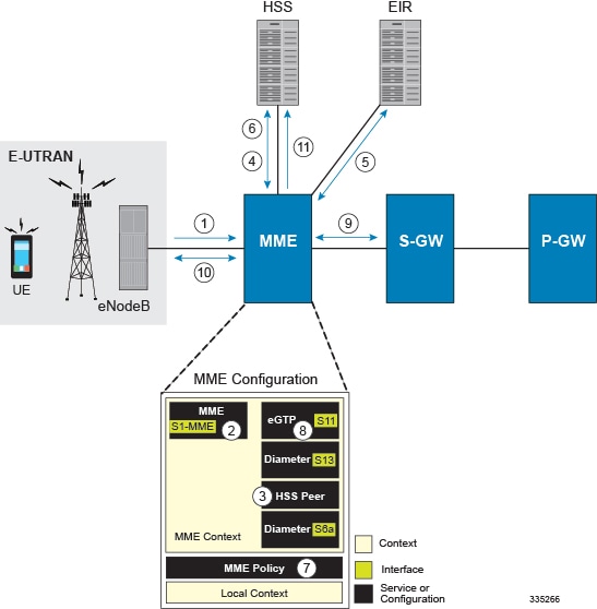
How This Configuration Works
The following figure and supporting text describe how this configuration with a single context is used by the system to process a subscriber call originating from the GTP LTE network.
-
The eNodeB forwards an Attach Request message from the UE to the MME containing the IMSI, last visited TAI (if available), the UE's core network capability, the PDN Type, and the Attach Type.
-
The MME service receives the Attach Request message and references the HSS peer service for authentication and location resolution.
-
The HSS peer service configuration specifies the Diameter configuration and S6a interface to use to communicate with the HSS and the Diameter configuration and S13 interface to use to communicate with the Equipment Identity Register (EIR).
-
Assuming that the MME has no previous security context, it sends an S6a Authentication Request to the HSS and uses the authentication vectors received in the response to complete the authentication procedure with UE.
-
After authentication, the MME proceeds to do a security setup with the UE. During this procedure, the ME identity is transferred to the MME which then queries the EIR.
-
The MME then sends an Update Location Request to the HSS and obtains relevant subscription data for the IMSI in the response.
-
The MME policy is accessed to determine the S-GW and P-GW to which the UE should be attached.
-
The MME uses the S11 interface bound to the eGTP service to communicate with the S-GW specified by the MME policy configuration.
-
The MME then sends a Create Session Request to S-GW which is also forwarded to the specified P-GW (assuming GTP-S5/S8) P-GW establishes the S5/S8 GTPU bearers and then responds with a Create-Session-response which is forwarded to the MME by the S-GW. The S-GW includes the relevant S1-U bearer information.
-
The MME then sends a NAS Attach Accept embedded in the S1 Init Ctxt Setup request to the eNodeB. The Attach Accept contains the IP address allocated to the PDN and the temporary identifier (GUTI) assigned to the UE. The MME waits for positive acknowledgment from both the eNodeB (Init Ctxt Setup response) and UE (Attach Complete). The Init Ctxt Setup Response contains the S1-U bearer endpoint information. The MME then uses the S11 Modify Bearer Request to update the eNodeB endpoints with the S-GW. The receipt of the S11 Modify Bearer Response completes the end-to-end bearer setup.
-
The MME then uses the S6a Notify Request to update the HSS with the APN and P-GW identity.
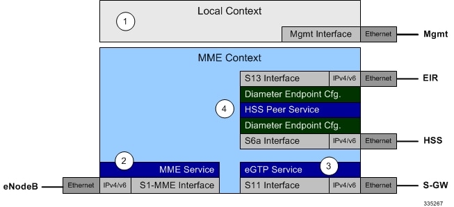
MME Configuration
To configure the system to perform as a standalone eGTP S-GW, review the following graphic and subsequent steps.
Creating and Configuring the MME Context and Service
Use the following example to configure the MME context and all supported interfaces:
configure
   context mme_context_name -noconfirm
      interface s1-mme_intf_name
         ip address ipv4_address
         exit
      interface s11_intf_name
         ip address ipv4_address
         exit
      interface s6a_intf_name
         ip address ipv4_address
         exit
      interface s13_intf_name
         ip address ipv4_address
         exit
      mme-service mme_svc_name -noconfirm
         mme-id group-id grp_id mme-code mme_code
         plmn-id mcc mcc_value mnc mnc_value
         network-sharing plmnid mcc mcc_value mnc mnc_value mme-id group-id id mme-code code
         associate egtp-service egtp-service_name context mme_context_name
         associate hss-peer-service hss_peer_service_name context mme_context_name
         policy attach imei-query-type imei-sv verify-equipment-identity
         pgw-address pgw_ip_address
         bind s1-mme ipv4-address ip_address
         exit
      exit
   port ethernet slot_number/port_number
      no shutdown
      bind interface s1-mme_intf_name mme_context_name
      end
Notes:
- All interfaces in this configuration can also be specified as IPv6 addresses using the ipv6 address command.
- Multi-homing is supported on the S1-MME and S6a interfaces. For more information on configuring multi-homing for the S1-MME and/or S6a interface(s), refer to Configuring SCTP Multi-homing Support.
- A maximum of 256 services (regardless of type) can be configured per system.
- The bind s1-mme command can also be specified as an IPv6 address using the ipv6-address keyword.
- The network-sharing command is used to configure an additional PLMN ID for this MME service.
- The eGTP service is configured in the following section.
- The HSS peer service is configured in the configuration sequence for Creating and Configuring the HSS Peer Service and Interface Associations.
- In the above example, the mobile equipment identity (IMEI) is checked during the attach procedure. This is configured in the policy attach command. Another option is to check IMEI during the tracking area update (TAU). This can be accomplished instead of, or, in addition to, the EIR query during the attach procedure. To check during the TAU, use the policy tau command.
- The pgw-address command is used to statically configure P-GW discovery.
Creating and Configuring the eGTP Service and Interface Association
Use the following example to create an eGTP service and associate it with the S11 interface.
configure
   context mme_context_name
      egtp-service egtp_service_name
         interface-type interface-mme
          gtpc bind ipv4-address s11_infc_ip_address
         exit
      exit
   port ethernet slot_number/port_number
      no shutdown
      bind interface s11_interface_name mme_context_name
      end
Creating and Configuring the HSS Peer Service and Interface Associations
Use the following example to create and configure the HSS peer service:
configure
   context mme_context_name
      hss-peer-service hss_peer_service_name
         diameter hss-endpoint hss_endpoint_name eir-endpoint eir-endpoint_name
         exit
      exit
      diameter endpoint hss-endpoint_name
            origin realm realm_name
            origin host name address S6a_interface_address
            peer peer_name realm realm_name address hss_ip_address
            route-entry realm realm_name peer peer_name
            exit
      diameter endpoint eir-endpoint_name
            origin realm realm_name
            origin host name address S13_interface_address
            peer peer_name realm realm_name address eir_ip_address
            route-entry realm realm_name peer peer_name
            exit
      port ethernet slot_number/port_number
            no shutdown
            bind interface s6a_interface_name mme_context_name
            exit
      port ethernet slot_number/port_number
            no shutdown
            bind interface s13_interface_name mme_context_name
            end
Notes:
- The origin host and peer commands can accept multiple IP addresses supporting multi-homing on each endpoint. For information on configuring SCTP multi-homing for the S6a interface, refer to Configuring SCTP Multi-homing Support.
Caution | On a PSC2 setup, all diamproxy tasks might go in to a warning state if the number of hss-peer-services configured are more than 64 since the memory usage may exceed the allocated value. |
Configuring Dynamic Destination Realm Construction for Foreign Subscribers
For a foreign subscriber, the MME does not know the HSS nodes in all the foreign PLMNs. In this case the MME routes S6a/S6d requests directed to foreign PLMNs via a Diameter Routing Agent (DRA) using only the destination realm. The DRA in turn routes the request to the correct HSS based on the destination realm. In order to accomplish this, the MME needs to dynamically construct requests to the DRA/HSS with a Destination Realm representing the foreign PLMN of the UE.
The MME can be configured to derive the EPC Home Network Realm/Domain based on the user's IMSI (MNC and MCC values) and use it as the Destination Realm in all diameter messages.
For home subscribers, the MME will always use the configured peer realm as destination-realm, regardless if dynamic-destination-realm is enabled.
Because MNCs can be 2 or 3 digits long, to provide the ability for an operator to configure the MCC and MNC of foreign PLMNs, the operator policy of the subscriber map is used to determine the MNC value and the length of the MNC. The following steps outline how this configuration can be implemented.
First, enable the dynamic destination realm functionality for the HSS Peer Service:
configure
   context ctxt_name
      hss-peer-service HSS1
         dynamic-destination-realm
         end
Then configure the foreign PLMNs in the LTE subscriber map. For example:
configure
   lte-policy
      subscriber map SM1
         precedence 10 match-criteria imsi mcc 232 mnc 11 operator-policy-name OP.HOME
         precedence 20 match-criteria imsi mcc 374 mnc 130 msin first 700000000 last 800000000 operator-policy-name OP.ROAMING
         end
Then associate the subscriber map to the MME Service. For example:
configure
   context ingress
      mme-service mmesvc
         associate subscriber-map SM1
         end
A static route entry must also be added in the diameter endpoint configuration for each foreign realm. For example:
configure
   context ingress
      diameter endpoint s6a1
         peer HSS1 realm HSS-Realm1 address ip-address sctp
         route-entry realm epc.mnc045.mcc123.3gppnetwork.org peer HSS1
         end
With this sample configuration, an MNC of length 2 and value of 11 is matched with first operator policy (OP.HOME), and an MNC length of 3 and value of 130 is matched with the second operator policy (OP.ROAMING). With this configuration, the MME will find the MNC based on the operator policy for the foreign subscriber.
If there is no matching entry present in the operator policy, the MME will use the global static table to decide the MNC length and pass that information to Diameter layer to construct the dynamic realm. The following list of MCCs are all considered as 3 digit MNCs. All other MCCs are considered 2 digit MNCs.
| 302 | 334 | 354 | 405 |
| 310 | 338 | 356 | 708 |
| 311 | 342 | 358 | 722 |
| 312 | 344 | 360 | 732 |
| 316 | 346 | 365 | |
| 348 | 376 |
The show hss-peer-service service name command displays this configuration in the Destination Realm field, either Configured Peer Realm (default), or Dynamic Realm.
Request Auth-vectors            : 1
Notify Request Message          : Enable
Destination Realm               : Dynamic Realm
Configuring Optional Features on the MME
The configuration examples in this section are optional and provided to cover the most common uses of the MME in a live network. The intent of these examples is to provide a base configuration for testing.
- Configuring Differentiation Between HeNB-GW and eNodeBs
- Configuring Dual Address Bearers
- Configuring Dynamic Peer Selection
- Configuring Emergency Session Support
- Configuring Gn/Gp Handover Capability
- Configuring Inter-MME Handover Support
- Configuring X.509 Certificate-based Peer Authentication
- Configuring Dynamic Node-to-Node IP Security on the S1-MME Interface
- Configuring ACL-based Node-to-Node IP Security on the S1-MME Interface
- Configuring Mobility Restriction Support
- Configuring S4-SGSN Handover Capability
- Configuring SCTP Multi-homing Support
- Configuring Static S-GW Pools
- Configuring UMTS to LTE ID Mapping
- Configuring User Location Information Reporting Support
Configuring Differentiation Between HeNB-GW and eNodeBs
The MME can be configured to distinguish the Home eNodeB Gateway (HeNB-GW) from other eNodeBs. This is required to support S1 handovers to Home eNodeBs connected via a HeNB-GW.
As per 3GPP TS 36.300, section 4.6.2, the TAI used in a HeNB-GW should not be reused in another HeNB-GW. The global eNodeB id of the HeNB-GW can now be configured within the lte-policy configuration mode.
In case of S1-based handovers to Home eNodeBs served by a HeNB-GW, the lookup at MME for the target eNodeB based on global ENB id will fail, as MME is aware of only the HeNB-GW. In those cases additional lookup needs to be done based on TAI to find the HeNB-GW serving the Home eNodeB.
This feature allows operators to configure the global eNodeB ids of HeNB-GWs in the MME service. The MME uses this information to perform HeNB-GW related functions.
The following steps create an HeNB-GW management database, configures a single Global eNodeB ID and TAI within the management database, and associates the HeNB-GW management database with the MME service:
configure
   lte-policy
      mme  henbgw  mgmt-db  db_name
         henbgw-global-enbid mcc mcc_value mnc mnc_value enbid enbid_value
         end
configure
   context  ctxt_name
      mme-service  svc_name
         associate henbgw-mgmt-db db_name
         end
- A maximum of 8 HeNB-GWs can be configured within the HeNB-GW management database.
- The show lte-policy henbgw-mgmt-db name db_name command displays configuration information about the specified HeNB-GW management database.
- The show mme-service enodeb-association full command displays whether the eNodeB is an HeNB-GW by including "(HeNB-GW)" in the output of the eNodeB Type field.
Configuring Dual Address Bearers
This example configures support for IPv4/v6 PDNs.
Use the following configuration example to enable support on the MME for dual-address bearers:
configure
   context mme_context_name -noconfirm
      mme-service mme_svc_name
         policy network dual-addressing-support
         end
Configuring Dynamic Peer Selection
The configuration in this section replaces static configurations on the MME for the following peer components: MME, P-GW, S-GW, SGSN.
Use the following example to configure dynamic P-GW, S-GW, and peer MME selection through a DNS interface:
configure
   context mme_context_name -noconfirm
      interface dns_intf_name
         ip address ipv4_address
         exit
      ip domain-lookup
      ip name-servers dns_ip_address
      dns-client name
         bind address dns_intf_ip_address
         exit
      mme-service mme_svc_name
         dns pgw
         dns sgw
         dns peer-mme
         dns peer-sgsn
         end
-
For the dns pgw, dns sgw, dns peer-mme, and dns peer-sgsn commands, the DNS client service must exist in the same context as the MME service. If the DNS client resides in a different context, the context command and ctx_name variable must be added to the command(s).
- If you have associated a tai-mgmt-db with a call-control-profile, and DNS is to be used for S-GW lookups, the DNS configuration must be configured within the same call-control-profile using the dns-sgw command present within the call-control-profile configuration mode.
Configuring Emergency Session Support
The configuration example in this section enables emergency bearer session support on the MME.
Use the following configuration example to enable emergency bearer services on the MME:
configure
   lte-policy
      lte-emergency-profile profile_name
         ambr max-ul bitrate max-dl bitrate
         apn apn_name pdn-type type
         pgw ip-address address protocol type weight value
         qos qci qci arp arp_value preemption-capability capability vulnerability type
         ue-validation-level type
         exit
      mme-service mme_svc_name
         associate lte-emergency-profile profile_name
         end
-
A maximum of four LTE emergency profiles can be configured on the system.
-
In the apn command, the valid PDN types are: ipv4, ipv4v6, and ipv6.
-
In the pgw command, the valid protocol types are: both, gtp, and pmip. A maximum of four P-GW IP addresses can be configured per profile. An FQDN can also be configured in place of the IP addresses but only one P-GW FQDN can be configured per profile.
-
In the qos command, the valid preemption capabilities are: may and shall not. The valid vulnerability types are: not-preemptable and preemptable.
-
The ue-validation-level types are: auth-only, full, imsi, and none.
- To configure the
MME to ignore the IMEI validation of the equipment during the attach procedure
in emergency cases, use the following command in the
mme-service
configuration mode:
policy attach imei-query-type imei | imei-sv | none verify-equipment-identity verify-emergency - To configure
the MME to ignore the IMEI validation of the equipment during TAU procedures in
emergency cases, use the following command in the
mme-service
configuration mode:
policy tau imei-query-type imei | imei-sv | none verify-equipment-identity verify-emergency
Configuring Gn/Gp Handover Capability
The example configuration in this section provides 3G to 4G handover capabilities between the MME and a Gn/Gp SGSN. The configuration creates the Gn interface used for control signaling during the handover.
Use the following configuration example to create a Gn interface and configure the control interface on the MME for Gn/Gp handovers:
configure
   context mme_context_name -noconfirm
      interface Gn_intf_name
         ip address ipv4_address
         exit
      sgtp-service sgtp_svc_name
         gtpc bind address Gn_intf_ip_address
         exit
      mme-service mme_svc_name
         associate sgtpc-service sgtp_svc_name
         peer-sgsn rai mcc mcc_value mnc mnc_value rac value lac value address ip_address capability gn
         nri length length plmn-id mcc mcc_value mnc mnc_value
         end
Notes:
- The peer-sgsn command is used to statically configure a peer SGSN. SGSN selection can also be performed dynamically through the DNS client. For more information about dynamic peer selection, refer to the Configuring Dynamic Peer Selection in this chapter.
- If dynamic peer-SGSN selection is configured, an additional gtpc command must be added to the SGTP service: gtpc dns-sgsn context cntxt_name
- In the absence of an NRI length configuration, the MME treats the NRI as invalid. The MME will use a plain RAI-based FQDN (and not an NRI-based FQDN) for DNS queries made to resolve the source SGSN.
Configuring Inter-MME Handover Support
Use the following example to configure inter-MME handover support:
configure
   context mme_context_name -noconfirm
      interface s10_intf_name
         ip address ipv4_address
         exit
      egtp-service egtp_service_name
         interface-type interface-mme
         gtpc bind ipv4-address s10_infc_ip_address
         exit
      exit
      mme-service mme_svc_name
         peer-mme gummei mcc number mnc number group-id id mme-code code address ipv4_address
         exit
      exit
   port ethernet slot_number/port_number
      no shutdown
      bind interface s10_interface_name mme_context_name
      end
Notes:
- The S10 IP address can also be specified as an IPv6 address. To support this, the ip address command can be changed to the ipv6 address command.
- The
peer-mme
command can also be configured to acquire a peer MME through the use of a TAI
match as shown in this command example:
peer-mme tai-match priority value mcc number mnc number tac any address ipv4_address - The peer-mme command is used to statically configure a peer MME. MME selection can also be performed dynamically through the DNS client. For more information about dynamic peer selection, refer to the Configuring Dynamic Peer Selection in this chapter.
- The peer MME IP address can also be specified as an IPv6 address.
Configuring X.509 Certificate-based Peer Authentication
The configuration example in this section enables X.509 certificate-based peer authentication, which can be used as the authentication method for IP Security on the MME.
Use of the IP Security feature requires that a valid license key be installed. Contact your local Sales or Support representative for information on how to obtain a license.
The following configuration example enables X.509 certificate-based peer authentication on the MME.
In Global Configuration Mode, specify the name of the X.509 certificate and CA certificate, as follows:
configure
   certificate name cert_name pem url cert_pem_url private-key pprivate-keyem url private_key_url
   ca-certificate name ca_cert_name pem url ca_cert_url
   end
When creating the crypto template for IPSec in the Context Configuration Mode, bind the X.509 certificate and CA certificate to the crypto template and enable X.509 certificate-based peer authentication for the local and remote nodes, as follows:
configure
   context mme_context_name
      crypto template crypto_template_name ikev2-dynamic
         certificate name cert_name
         ca-certificate list ca-cert-name ca_cert_name
         authentication local certificate
         authentication remote certificate
         end
-
A maximum of sixteen certificates and sixteen CA certificates are supported per system. One certificate is supported per service, and a maximum of four CA certificates can be bound to one crypto template.
-
The certificate name and ca-certificate list ca-cert-name commands bind the certificate and CA certificate to the crypto template.
-
The authentication local certificate and authentication remote certificate commands enable X.509 certificate-based peer authentication for the local and remote nodes.
Configuring Dynamic Node-to-Node IP Security on the S1-MME Interface
The configuration example in this section creates an IKEv2/IPSec dynamic node-to-node tunnel endpoint on the S1-MME interface.
Use of the IP Security feature requires that a valid license key be installed. Contact your local Sales or Support representative for information on how to obtain a license.
- Creating and Configuring an IPSec Transform Set
- Creating and Configuring an IKEv2 Transform Set
- Creating and Configuring a Crypto Template
- Binding the S1-MME IP Address to the Crypto Template
Creating and Configuring an IPSec Transform Set
The following example configures an IPSec transform set which is used to define the security association that determines the protocols used to protect the data on the interface:
configure
      context <mme_context_name>
            ipsec transform-set <ipsec_transform-set_name>
                  encryption aes-cbc-128
                  group none
                  hmac sha1-96
                  mode tunnel
                  end
-
The encryption algorithm, aes-cbc-128, or Advanced Encryption Standard Cipher Block Chaining, is the default algorithm for IPSec transform sets configured on the system.
-
The group none command specifies that no crypto strength is included and that Perfect Forward Secrecy is disabled. This is the default setting for IPSec transform sets configured on the system.
-
The hmac command configures the Encapsulating Security Payload (ESP) integrity algorithm. The sha1-96 keyword uses a 160-bit secret key to produce a 160-bit authenticator value. This is the default setting for IPSec transform sets configured on the system.
-
The mode tunnel command specifies that the entire packet is to be encapsulated by the IPSec header including the IP header. This is the default setting for IPSec transform sets configured on the system.
Creating and Configuring an IKEv2 Transform Set
The following example configures an IKEv2 transform set:
configure
      context <mme_context_name>
            ikev2-ikesa transform-set <ikev2_transform-set_name>
                  encryption aes-cbc-128
                  group 2
                  hmac sha1-96
                  lifetime <sec>
                  prf sha1
                  end
-
The encryption algorithm, aes-cbc-128, or Advanced Encryption Standard Cipher Block Chaining, is the default algorithm for IKEv2 transform sets configured on the system.
-
The group 2 command specifies the Diffie-Hellman algorithm as Group 2, indicating medium security. The Diffie-Hellman algorithm controls the strength of the crypto exponentials. This is the default setting for IKEv2 transform sets configured on the system.
-
The hmac command configures the Encapsulating Security Payload (ESP) integrity algorithm. The sha1-96 keyword uses a 160-bit secret key to produce a 160-bit authenticator value. This is the default setting for IKEv2 transform sets configured on the system.
-
The lifetime command configures the time the security key is allowed to exist, in seconds.
-
The prf command configures the IKE Pseudo-random Function, which produces a string of bits that cannot be distinguished from a random bit string without knowledge of the secret key. The sha1 keyword uses a 160-bit secret key to produce a 160-bit authenticator value. This is the default setting for IKEv2 transform sets configured on the system.
Creating and Configuring a Crypto Template
The following example configures an IKEv2 crypto template:
configure
      context <mme_context_name>
            crypto template <crypto_template_name> ikev2-dynamic
                  authentication local pre-shared-key key <text>
                  authentication remote pre-shared-key key <text>
                  ikev2-ikesa transform-set list <name1> . . . <name6>
                  ikevs-ikesa rekey
                  payload <name> match childsa match ipv4
                        ipsec transform-set list <name1> . . . <name4>
                        rekey
                        end
Binding the S1-MME IP Address to the Crypto Template
The following example configures the binding of the S1-MME interface to the crypto template:
configure
      context <mme_context_name>
            mme-service <mme_svc_name>
                  bind s1-mme ipv4-address <address> ipv4-address <address> crypto-template <enodeb_crypto_template>
                  end
Configuring ACL-based Node-to-Node IP Security on the S1-MME Interface
The configuration example in this section creates an IKEv2/IPSec ACL-based node-to-node tunnel endpoint on the S1-MME interface.
Use of the IP Security feature requires that a valid license key be installed. Contact your local Sales or Support representative for information on how to obtain a license.
- Creating and Configuring a Crypto Access Control List
- Creating and Configuring an IPSec Transform Set
- Creating and Configuring an IKEv2 Transform Set
- Creating and Configuring a Crypto Map
Creating and Configuring a Crypto Access Control List
The following example configures a crypto ACL (Access Control List), which defines the matching criteria used for routing subscriber data packets over an IPSec tunnel:
configure
      context <mme_context_name>
            ip access-list <acl_name>
                  permit tcp host <source_host_address> host <dest_host_address>
                  end
Creating and Configuring an IPSec Transform Set
The following example configures an IPSec transform set which is used to define the security association that determines the protocols used to protect the data on the interface:
configure
      context <mme_context_name>
            ipsec transform-set <ipsec_transform-set_name>
                  encryption aes-cbc-128
                  group none
                  hmac sha1-96
                  mode tunnel
                  end
-
The encryption algorithm, aes-cbc-128, or Advanced Encryption Standard Cipher Block Chaining, is the default algorithm for IPSec transform sets configured on the system.
-
The group none command specifies that no crypto strength is included and that Perfect Forward Secrecy is disabled. This is the default setting for IPSec transform sets configured on the system.
-
The hmac command configures the Encapsulating Security Payload (ESP) integrity algorithm. The sha1-96 keyword uses a 160-bit secret key to produce a 160-bit authenticator value. This is the default setting for IPSec transform sets configured on the system.
-
The mode tunnel command specifies that the entire packet is to be encapsulated by the IPSec header including the IP header. This is the default setting for IPSec transform sets configured on the system.
Creating and Configuring an IKEv2 Transform Set
The following example configures an IKEv2 transform set:
configure
      context <mme_context_name>
            ikev2-ikesa transform-set <ikev2_transform-set_name>
                  encryption aes-cbc-128
                  group 2
                  hmac sha1-96
                  lifetime <sec>
                  prf sha1
                  end
-
The encryption algorithm, aes-cbc-128, or Advanced Encryption Standard Cipher Block Chaining, is the default algorithm for IKEv2 transform sets configured on the system.
-
The group 2 command specifies the Diffie-Hellman algorithm as Group 2, indicating medium security. The Diffie-Hellman algorithm controls the strength of the crypto exponentials. This is the default setting for IKEv2 transform sets configured on the system.
-
The hmac command configures the Encapsulating Security Payload (ESP) integrity algorithm. The sha1-96 keyword uses a 160-bit secret key to produce a 160-bit authenticator value. This is the default setting for IKEv2 transform sets configured on the system.
-
The lifetime command configures the time the security key is allowed to exist, in seconds.
-
The prf command configures the IKE Pseudo-random Function which produces a string of bits that cannot be distinguished from a random bit string without knowledge of the secret key. The sha1 keyword uses a 160-bit secret key to produce a 160-bit authenticator value. This is the default setting for IKEv2 transform sets configured on the system.
Creating and Configuring a Crypto Map
The following example configures an IKEv2 crypto map:
configure
      context <mme_context_name>
            crypto map <crypto_map_name> ikev2-ipv4
                  match address <acl_name>
                  peer <ipv4_address>
                  authentication local pre-shared-key key <text>
                  authentication remote pre-shared-key key <text>
                  ikev2-ikesa transform-set list  <name1> . . .  <name6>
                  payload <name> match ipv4
                        lifetime <seconds>
                        ipsec transform-set list <name1> . . . <name4>
                        exit
                  exit
            interface <s1-mme_intf_name>
                  ip address <ipv4_address>
                  crypto-map <crypto_map_name>
                  exit
            exit
      port ethernet <slot_number/port_number>
            no shutdown
            bind interface <s1-mme_intf_name> <mme_context_name>
            end
Configuring Mobility Restriction Support
Mobility or handover restriction is performed by handover restriction lists configured on the MME. These lists restrict inter-RAT, 3G location area, and/or 4G tracking area handovers based on the configuration in the Handover Restriction List Configuration Mode.
Mobility restriction support is only available through the operator policy configuration. For more information on operator policy, refer to the Operator Policy chapter in this guide.
- Configuring Inter-RAT Handover Restrictions on the MME
- Configuring Location Area Handover Restrictions on the MME
- Configuring Tracking Area Handover Restrictions on the MME
Configuring Inter-RAT Handover Restrictions on the MME
Inter-RAT handover restriction configurations on the MME restrict subscribers from participating in handovers to defined radio access network types.
Use the following example to configure this feature:
configure
      lte-policy
            ho-restrict-list <name>
                  forbidden inter-rat cdma2000
                  end
Configuring Location Area Handover Restrictions on the MME
Location area handover restriction lists on the MME restrict subscribers from participating in handovers to specific 3G location area codes.
Use the following example to configure this feature:
configure
   lte-policy
      ho-restrict-list name
         forbidden location-area plmnid id
            lac area_code area_code area_code +
            end
-
Up to 16 forbidden location areas can be configured per handover restriction list.
-
Up to 128 location area codes can be entered in a single lac command line.
-
This configuration will only become operational when it is associated with a call control profile. Only one handover restriction list can be associated with a call control profile.
Configuring Tracking Area Handover Restrictions on the MME
Tracking area handover restriction lists on the MME restrict subscribers from participating in handovers to specific 4G tracking area codes.
Use the following example to configure this feature:
configure
   lte-policy
      ho-restrict-list name
         forbidden tracking-area plmnid id
            tac area_code [ area_code + ]
            end
-
Up to 16 forbidden tracking areas can be configured per handover restriction list.
-
Up to 128 tracking area codes can be entered in a single tac command line.
-
This configuration will only become operational when it is associated with a call control profile. Only one handover restriction list can be associated with a call control profile.
Configuring S4-SGSN Handover Capability
This configuration example configures an S3 interface supporting inter-RAT handovers between the MME and an S4-SGSN.
Use the following example to configure this feature:
configure
   context mme_context_name -noconfirm
      interface s3_interface_name
         ip address ipv4_address
         exit
      mme-service mme_svc_name
         peer-sgsn rai mcc mcc_value mnc mnc_value rac value lac value address ip_address capability s3
         nri length length plmn-id mcc mcc_value mnc mnc_value
         exit
      exit
   port ethernet slot_number/port_number
      no shutdown
      bind interface s3_interface_name mme_context_name
      end
Notes:
- The S3 IP address can also be specified as an IPv6 address. To support this, the ip address command can be changed to the ipv6 address command.
- The peer-sgsn command is used to statically configure a peer SGSN. SGSN selection can also be performed dynamically through the DNS client. For more information about dynamic peer selection, refer to the Configuring Dynamic Peer Selection section in this chapter.
- In the absence of an NRI length configuration, the MME treats the NRI as invalid. The MME will use a plain RAI-based FQDN (and not an NRI-based FQDN) for DNS queries made to resolve the source SGSN.
Configuring SCTP Multi-homing Support
SCTP multi-homing can be configured on the S1-MME interface (to/from eNodeB), the S6a interface (to/from HLR/HSS), and the SGs interface (to/from the MSC/VLR).
- Configuring SCTP Multi-homing on the S1-MME Interface
- Configuring SCTP Multi-homing on the S6a Interface
- Configuring S6a SCTP and Application Timers for Multi-homing
- Configuring SCTP Multi-homing on the SGs Interface
- SCTP Parameters for MME
Configuring SCTP Multi-homing on the S1-MME Interface
Up to two IPv4 or IPv6 addresses for the S1-MME interface can be entered to allow for SCTP multi-homing.
The configuration example in this section is intended as a replacement for the S1-MME interface configuration located in the section for Creating and Configuring the MME Context and Service. Use the following example to configure S1-MME multi-homing between the MME and the eNodeB:
configure
   context mme_context_name -noconfirm
      interface s1-mme_intf_name
         ip address ipv4_address
         ip address secondary_ipv4_address
         exit
      mme-service mme_svc_name
         bind s1-mme ipv4-address ipv4_address ipv4-address secondary_ipv4_address
         exit
      exit
   port ethernet slot_number/port_number
      no shutdown
      bind interface s1-mme_intf_name mme_context_name
      end
Configuring SCTP Multi-homing on the S6a Interface
Up to four IPv4 or IPv6 addresses for the S6a interface can be configured to allow for SCTP multi-homing.
The configuration example in this section is intended as a replacement for the S6a interface configuration located in Creating and Configuring the MME Context and Service section and the Diameter configuration for the S6a interface located in Creating and Configuring the HSS Peer Service and Interface Associations . Use the following example to configure S6a multi-homing between the MME and the HLR/HSS:
configure
   context mme_context_name
      interface s6a_intf_name
         ip address s6a_intf_primary_ip_addr ip_mask
         ip address s6a_intf_secondary_ip_addr2 ip_mask secondary
         ip address s6a_intf_secondary_ip_addr3 ip_mask secondary
         exit
      exit
   diameter endpoint hss-endpoint_name
      origin realm realm_name
      origin host name address s6a_intf_primary_ip_addr port number address s6a_intf_secondary_ip_addr2 port number address s6a_intf_secondary_ip_addr3 port number
      peer peer_name realm realm_name address hss_ip_addr1 port number address hss_ip_addr2 port number sctp
      route-entry realm realm_name peer peer_name
      exit
   port ethernet slot_number/port_number
      no shutdown
      bind interface s6a_intf_name mme_context_name
      exit
Configuring S6a SCTP and Application Timers for Multi-homing
In the event of a path failure, the SCTP multi-homing feature requires time to activate the alternate path. Timers associated with the SCTP heartbeat and the application in this instance, a Diameter watchdog request, must be tuned properly to ensure that the application does not timeout before the redundant SCTP path can be activated. The required calculation is based on the two paths configured between the MME and the HSS, the maximum retransmission configuration for the SCTP paths, and the SCTP heartbeat timeout configuration. The configuration of the timers must be identical on both peers.
The recommended SCTP timer values are provided below in the first row for the Diameter application default values that follow the typical case of two paths between the MME and HSS SCTP peers. SCTP HB interval can be in the range of 1 to 10 seconds, since (10 sec x 1 retx x 2 paths = 20 seconds) (30 sec watchdog timeout x 1 retry).
The second row displays the recommended configuration using the same Diameter defaults but providing a SCTP heartbeat timer that reduces heartbeat traffic.
| SCTP Heartbeat Timeout | SCTP Path Max Retransmissions | Diameter Device Watchdog Timeout | Diameter Watchdog Request Max Retries |
|---|---|---|---|
|
1-10 range |
1 |
30 (default) |
1 (default) |
|
5 |
1 |
30 (default) |
1 (default) |
The following example configures the SCTP and application timers for the S6a SCTP interface supporting multi-homing:
configure
   sctp-param-template name
      sctp-max-path-retx value
      timeout sctp-heart-beat value
      exit
   context name
      diameter endpoint endpoint_name
         associate sctp-parameter-template template_name
         device-watchdog-request max-retries retry_count
         watchdog-timeout timeout
         end
Configuring SCTP Multi-homing on the SGs Interface
Up to two IPv4 or IPv6 addresses for the SGs interface can be entered to allow for SCTP multi-homing.
Use the following example to configure SGs multi-homing between the MME and the MSC/VLR:
configure
   context mme_context_name -noconfirm
      interface s1-mme_intf_name
         ip address ipv4_address
         ip address secondary_ipv4_address
         exit
      sgs-service mme_svc_name
         bind ipv4-address ipv4_address ipv4-address secondary_ipv4_address
         exit
      exit
   port ethernet slot_number/port_number
      no shutdown
      bind interface sgs_intf_name mme_context_name
      end
SCTP Parameters for MME
The details on the configurable values for SCTP parameters are provided in the table given below:
|
Parameter |
Minimum value |
Maximum value |
Granularity |
|---|---|---|---|
|
RTO.min |
10ms |
5s |
10ms |
|
RTO.max |
500ms |
120s |
10ms |
|
RTO.initial |
RTO.min |
RTO.max |
10ms |
|
RTO.alpha |
1/8 |
1/8 |
- |
|
RTO.beta |
1/4 |
1/4 |
- |
|
Valid.Cookie.Life |
5s |
120s |
1s |
|
HB.interval |
1s |
300s |
1s |
|
SACK period |
0ms |
500ms |
10ms |
|
SACK frequency |
1 |
5 |
1 |
|
MTU size |
508 bytes |
65535 bytes |
1 byte |
The details on the default values for SCTP parameters are provided in the table given below:
|
Parameter |
Default value |
|---|---|
|
RTO Alpha |
5 |
|
RTO Beta |
10 |
|
Valid Cookie Life |
600 |
|
Max. associate retransmission value |
10 |
|
Max. number of outgoing streams |
16 |
|
Max. number of incoming streams |
16 |
|
Max. retransmission initiations |
5 |
|
Max. MTU size |
1500 |
|
Min. MTU size |
508 |
|
Start MTU |
1500 |
|
Max. path retransmission |
5 |
|
RTO Initital |
30 |
|
RTO Max |
600 |
|
RTO Min |
10 |
|
HB interval |
30 |
|
HB enable |
True |
|
SACK period |
2 |
|
SACK frequency |
2 |
|
Bundle valid |
True |
|
Bundle enable |
False |
Configuring Static S-GW Pools
The MME supports static TAI list configuration which allows for the mapping of TAIs, TACs, and S-GWs to facilitate S-GW pooling for UEs moving between TAIs in their TAI lists.
- Creating and Configuring a TAI Management Database and Object
- Associating a TAI Management Database with an MME Service
- Associating a TAI Management Database with a Call Control Profile
Creating and Configuring a TAI Management Database and Object
This section provides configuration examples for creating and configuring the TAI/S-GW associations for S-GW pooling.
Use the following example to configure this feature on the MME:
configure
   lte-policy
      tai-mgmt-db db_name
         tai-mgmt-obj object_name
         tai mcc number mnc number tac value
         sgw-address ipv4_address s5-s8-protocol gtp weight number
         end
-
Up to four databases can be configured on the system.
-
Up to 500 management objects can be configured per database.
-
Up to 16 TAIs can be configured per management object.
-
Up to 16 TACs can be configured per TAI.
-
The sgw-address variable can also be specified as an IPv6 address.
-
Up to 32 S-GW IP addresses can be configured per management object.
-
Weights for IPv4 addresses are ignored if IPv6 addresses are present meaning only IPv6 addresses are load-balanced if present.
-
The s5-s8-protocol can also be specified as pmip or both (GTP and PMIP).
Associating a TAI Management Database with an MME Service
In order for an MME service to use a statically configured S-GW pool, it must be associated with the TAI Management Database.
Use the following example to configure the TAI Management Database-to-MME service association:
configure
   context mme_context_name
      mme-service mme_svc_name
         associate tai-mgmt-db database_name
         end
Associating a TAI Management Database with a Call Control Profile
MME service can access a statically configured S-GW pool through an Operator Policy instance, specifically through the Call Control Profile.
Use the following example to configure the TAI Management Database-to-MME service association:
configure
   call-control-profile name
      associate tai-mgmt-db database_name
      end
-
Only one TAI Management Database can be configured per Call Control Profile.
- This association can also be performed in the MME Service Configuration Mode. If both associations are configured, the Operator Policy association is preferred by the system.
- If the tai-mgmt-db is associated with a call-control-profile, and DNS is to be used for S-GW lookups, the DNS configuration must be configured within the same call-control-profile using the dns-sgw command within the call-control-profile configuration mode.
Configuring UMTS to LTE ID Mapping
UMTS networks are configured with LACs allocated from the reserved space of 32K to 64K. In LTE networks, this space is typically reserved for MME group IDs. To overcome this issue during inter-RAT handovers, the MME can be configured with mappings between LACs and MME group IDs.
Use the following configuration example to map PLMN IDs to MME group IDs:
configure
   lte-policy
      network-global-mme-id-mgmt-db
         plmn mcc mcc_value mnc mnc_value mme-group-id-range first id last id
         exit
      exit
   context mme_service_context
      mme-service service_name
         associate network-global-mme-id-mgmt-db
         end
Configuring User Location Information Reporting Support
This feature allows the MME to query and receive UE location reports from an eNodeB.
 Note | User Location Information Reporting is a licensed feature and requires the purchase of the ULI Reporting feature license to enable it. |
Use the following example to configure User Location Information (ULI) reporting support on the MME:
configure
   context mme_context_name
      mme-service mme_svc_name
         location-reporting
         end
 Feedback