Wireless Settings

This chapter contains the following sections:

About WLANs in CBW Access Point Network

A Wireless Local Area Network (WLAN) is a network that allows devices to connect and communicate on wireless mode.

You can create and manage WLANs using the WLANs screen. This is discussed in the following sections.

Setting Up WLANs and WLAN Users

Open Wireless Settings > WLANs.

The total number of active WLANs is displayed at the top of the WLANs window which includes a list of WLANs currently configured on the Primary AP. The following details are displayed for each WLAN:

  • Status of the WLAN (enabled or disabled)

  • Name

  • Security Policy

  • Radio Policy

Setting Up Guidelines

  • You can associate up to 16 WLANs with the CBW Primary AP and create a total of 16 WLANs. Cisco recommends a maximum of 4 WLANs. The Primary AP assigns all the configured WLANs to all the connected APs.

  • Each WLAN has a unique WLAN ID, a unique profile name, and an SSID.

  • The Profile name and SSID can have up to 31 characters.

  • Each connected AP advertises only the WLANs that are in an Enabled state. The APs do not broadcast disabled WLANs.

  • Peer-to-peer blocking does not apply to multicast traffic.

  • You cannot map a WLAN to VLAN0, and you cannot map VLANs 1002 to 1006.

  • Dual-stack clients with static IPv4 addresses are not supported.

  • Profile name and security type must be unique for each WLAN.

Viewing WLANs

To view details of configured WLANs, navigate to Wireless Settings > WLANs.

The WLANs window lists all the WLANs that are currently configured on the Primary AP.

Action

Provides the option to Edit or Delete the WLAN.

Active

Shows the status of the WLAN as enabled or disabled.

Type

Displays the type as WLAN.

Name

Profile Name of the WLAN.

Several WLANs can be configured with the same SSID name but with a unique policy name and security mechanisms.

SSID

Service Set Identifier (SSID) name of the WLAN.

Security Policy

Indicates the Security Type of the WLAN. It can be an Open network, WPA2 Personal, WPA2+WPA3 (Personal), WPA3 Personal, WPA2 Enterprise, Central Web Auth (CWA), or a guest network.

MAC filtering

This option is displayed when you configure a Security Type with MAC Filtering enabled in the previous field. For example, when you configure a Open WLAN with the MAC Filtering enabled, then it displays Open+Macfilter.

Radio Policy

Displays the Radio in which the WLAN is broadcasting. By default, it is All.


Note


See About WLANs in CBW Access Point Network for a brief explanation on WLANs.


Tip


The total number of active WLANs is displayed at the top of the page. If the list of WLANs spans multiple pages, you can browse these pages by clicking the page number links or the forward and backward icons.


Adding and Modifying WLANs

This section describes how to add, modify, or delete a WLAN.

To add a WLAN

  1. Navigate to Wireless Settings > WLANs.

  2. In the WLANs window, click the Add new WLAN button to open the Add new WLAN window.

  3. Click Yes in the pop-up message.

  4. Open each tab and make your selections to set up the WLAN.

    Each of the tabs in this window is explained in the following sections.

  5. Click Apply to save the configurations or Cancel to discard the changes.

To edit a WLAN

  1. Click the Edit icon next to the WLAN you want to modify.


    Note


    Editing the WLAN will disrupt the network momentarily.


  2. Open each tab and make your edits to the WLAN.

  3. Click Apply to save the configurations, or Cancel to discard the changes.

For details on how to delete WLANs see Editing and Deleting WLANs.

Configuring General Details

Navigate to Wireless Settings > WLANs > Add new WLAN > General.

Under the General tab, set the following parameters:

WLAN ID

From the drop-down list, choose an ID number for the WLAN.

Type

Indicates if the type of network is WLAN. Choose WLAN option.

Profile Name

The profile name must be unique and should not exceed 31 characters.

SSID

The profile name also acts as the SSID. You can define an SSID that is different from the WLAN profile name. The SSID must be unique and should not exceed 31 characters.

Enable

Click this tab to enable/disable the WLAN.

Radio Policy

Click the drop-down list and choose from the following options:

  • All—Configures the WLAN to support dual-band (2.4GHz and 5GHz) capable clients.

  • 2.4GHz only—Configures the WLAN to support 802.11b/g/n/ax capable clients only.

  • 5GHz only—Configures the WLAN to support 802.11a/n/ac/ax capable clients only.

Broadcast SSID

The default is Enabled for the SSID to be discovered. Use the toggle button to hide the SSID.

Local Profiling

By default, this option is disabled. Enable this option to view the Operating System that is running on the Client or to see the User name.

Configuring the WLAN Security

Navigate to Wireless Settings>WLANsAdd new WLANWLAN Security.

Under the WLAN Security tab set the following parameters.

Guest Network

Guest user access can be provided on WLANs which are specifically designated for use by guest users. If the Guest Network is enabled, then the WLAN is considered as Guest WLAN. By default, this field is disabled.

The following fields are displayed when you Enable the Guest Network option. These are applicable for WLANs and Guest WLANs.

For details on creating a Guest Network, refer to Creating a Guest Network.

Captive Network Assistant

This feature detects the presence of a captive portal by sending a web request on connecting to a wireless network. This request is directed to a URL for iPhone models, and if a response is received, then the Internet access is assumed available and no further interaction is required.

If no response is received, then the Internet access is assumed to be blocked by the captive portal and Apple’s Captive Network Assistant (CNA) auto-launches the pseudo-browser to request portal login in a controlled window.

MAC Filtering

You can also restrict or permit a particular client joining your network by enabling the MAC Filtering feature. For details, refer to Blocking and Unblocking Clients.

When MAC Filtering is enabled on the WLAN, the client MAC address must be added to the Local MAC Addresses list by navigating to Wireless Settings>WLAN UsersLocal MAC Addresses with the Type as Allowlist for enabling the client to join the network via that SSID.

Captive Portal

This field is visible only when the Guest Network option is enabled. This is used to select the type of web portal that can be used for authentication purposes. Following are the types of web portals that you can choose.

  • Internal Splash Page: Choose this option to have a default Cisco web portal based authentication.

  • External Splash Page: Choose this option to have external captive portal authentication, using a web server outside your network. Also, select the URL of the server in the Captive Portal URL field.

Ensure to add this URL rule in the configuring ACL name under Advanced >Security Settings page.

Access Type

This field is visible only when the Guest Network option is enabled.

  • Local User Account: This is the default option. Choose this option to authenticate guests using the username and password which you can set for guest users of this WLAN, under Wireless Settings > WLAN Users. For more information, see Viewing and Managing WLAN Users

  • Web Consent: Choose this option to allow guests access to the WLAN upon acceptance of displayed terms and conditions. This option allows guest users to access the WLAN without entering a username and password.

  • Email Address: Choose this option if you want guest users to be prompted for their e-mail address when attempting to access the WLAN. Access to the Internet is provided when a valid email address is entered. This option allows guest users to access the WLAN without entering a username and password.

    You can also collect the email address information by configuring Accounting Radius Server under Management>Admin Accounts Radius in Expert View. By default, the email address will be sent to the first Radius server configured.

  • RADIUS: Refers to details on RADIUS in the Security Type-WPA2 Enterprise section.

  • WPA2 Personal: Refers to Security Type-Personal in the following section.

  • Social Login: Choose this option to allow guest access to WLAN upon authentication by Google/Facebook using their personal credentials. Once the user connects to this guest WLAN they will be redirected to Cisco default login page where they can find the login buttons for Google and Facebook. Once the user logs in using their Google/Facebook account, the user will get Internet access.

    If Social Login Access type is selected, the two toggle options will be displayed:

    • Facebook —Turn on this option when you want to allow a guest user access only using Facebook accounts.

    • Google—Turn on this option when you want to allow a guest user access only using Google accounts.

    By default both toggles are enabled, so guest users can use Facebook or Google accounts for authentication.

    Apple devices will not be able to sign-in via Google, if Captive Network Assistant (CNA) is enabled with Social Login as Access Type. You will need to disable CNA and sign-in via Google for Guest access.

ACL Name(IPv4)

This field is visible only when the Guest Network option is enabled.

For a detailed explanation on this feature refer to Configuring Access Control Lists (ACL). This description is applicable for WLAN and Guest WLAN.

Any ACL created through Advanced >Security SettingsAdd new ACL is also displayed here.

  • None: No ACL is applied.

  • Enable Social Login: This is a default setting. The user can map this when required to configure a Guest WLAN with Social Login as Access type.

  • Enable Facebook Login: The user can map to this when required to configure a Guest WLAN with Social Login as Access type and the Facebook toggle is enabled.

  • Enable Google Login: The user can map to this when required to configure a Guest WLAN with Social Login as Access type and the Google toggle is enabled.

ACL Name(IPv6)

This field is visible only when the Guest Network option is enabled.

Security Type

For details on this option, refer to the following section.

Security Type is displayed when the Guest Network option is disabled.

Each of the options available in the Security Type drop-down is explained in detail below.

Security Type-Open

This option stands for Open Authentication, which allows any device to authenticate and then attempt to communicate with an AP. Using Open Authentication, any wireless device can authenticate with the AP.

Security Type-Personal
WPA2

This option stands for Wi-Fi Protected Access 2 with Pre-Shared Key (PSK). WPA2 Personal is a method used for securing your network with the use of a PSK authentication. The PSK is configured separately both on the Primary AP, under the WLAN security policy, and on the client. WPA2 Personal does not rely on an authentication server on your network. By default, it is enabled.

WPA3

This option stands for Wi-Fi Protected Access 3 (WPA3), the latest version of Wi-Fi Protected Access (WPA), which is a suite of protocols and technologies that provide authentication and encryption for Wi-Fi networks. WPA3 leverages Simultaneous Authentication of Equals (SAE) to provide stronger protections for users against password guessing attempts by third parties. When the client connects to the Access Point, they perform an SAE exchange. If successful, they will each create a cryptographically strong key, from which the session key will be derived. Typically, a client and Access Point goes into phases of commit and then confirm. Once there is a commitment, the client and Access Point can then go into the confirm states each time there is a session key to be generated.

For advanced security, enable WPA3 in addition to WPA2. By default, the value is disabled.

You can also enable WPA3 individually, provided the client is WPA3 compatible.

Passphrase Format

Choose ASCII or HEX (hexadecimal range) from the PSK Format drop-down list and then enter a pre-shared key in the text box. WPA pre-shared keys must contain 8 to 63 ASCII text characters or 64 hexadecimal characters.

Passphrase

Create the password.

The PSK you enter is hidden under the dots for security purposes.

Confirm Passphrase

Retype the password to confirm it.

Show Passphrase

Check the box if you would like to display the password that was entered for verification.

Password Expiry

This option helps to enable password expiry for WLANs with WPA-PSK. By default, the password expiry is disabled.

Expiry (Days)

Set Value for expiry in days. Range: 1 - 180 days. By default, 180 days will be set as expiry value. This field is displayed when you enable the Password Expiry toggle switch.

Once the expiry value is exceeded, the WLAN will be disabled. If required, re-enable the WLAN and set the expiry value.

Security Type-WPA2 Enterprise

This option stands for Wi-Fi Protected Access 2, with a local authentication server or a RADIUS server. When you choose this option, you will see the following fields:

Authentication Server

You can choose External Radius or AP. The default option is External Radius.

  • To have a local authentication method, choose AP in the Authentication Server drop-down list. This option is a Local EAP authentication method that allows users and wireless clients to be authenticated locally. The Primary AP serves as the authentication server and the local user database, which removes dependency on an external authentication server.

    You will see a note specifying whether the Radius Server is configured for Authentication and Accounting. Radius Server can be configured by navigating to Admin Accounts.>RADIUS in Expert view.

  • To have a RADIUS server-based authentication method, choose External Radius in the Authentication Server drop-down list. RADIUS is a client/server protocol that enables communication with a central server to authenticate users and authorize their access to the WLAN.

Radius Profiling

The Primary AP acts as the collector of the information and sends the RADIUS server with the required data in an optimal form. Clients on the WLANS will be profiled as soon as profiling is enabled.

  • Profiling can be based on the following:

  • Role defining the user type or the user group to which the user belongs.

  • Device type, such as a Windows machine, Smart Phone, iPad, iPhone and Android device.

  • Username / password.

  • Location based on the AP group to which the client is connected.

  • Time of the day based on what time of the day the client is allowed on the network.

BYOD

Cisco provides a comprehensive Bring Your Own Device (BYOD) solution architecture, combining elements across the network for a unified approach to secure device access. It is enabled when a user wants to connect their personal devices in a more secure manner.

Security Type-Central Web Auth

It is a method of authentication in which the host’s Web browser is redirected to a RADIUS server. The RADIUS server provides a web portal where the user can enter a username and password. If these credentials are validated by the RADIUS server, the user is authenticated and is allowed access to the network. When you choose this option, you will see the following fields:

Radius Profiling

Refer to Radius Profiling in the table above for more information.

RADIUS Server

RADIUS is a client/server protocol that enables communication with a central server to authenticate users and authorize their access to the WLAN. To have a RADIUS server-based authentication method, choose External Radius in the Authentication Server drop-down list.

This section appears in UI, when you do the following:

  • Set the WLAN security to WPA2 Enterprise with Authentication Server and choose External Radius.

  • Set the WLAN security to Central Web Auth.

  • Set the WLAN security to WPA2/WPA3 Personal, and enable the MAC filtering toggle button.

The following fields are visible for the Security Types WPA2 Enterprise and Central Web Auth.

Radius Server

Provided for external authentication when you connect to a WLAN.

Authentication Caching

This feature helps store the client information essential for authentication locally in the cache on the CBW. This happens when the authentication with the RADIUS Server is successful. If the connectivity to the RADIUS server is lost, the information stored in the cache is used for authenticating the clients. You can also configure cache when the RADIUS Server is up and running. If the client details are not available locally, the request for authentication is sent through the RADIUS Server disabled.

This is field is not visible for the security type Central Web Auth.

When you enable this option, the following fields are displayed.

  • User Cache Timeout: Specifies the time period at which the authenticated credential in the cache expires.

    If the client's cache that expires is associated to the Primary AP, then it would get de-authenticated

    Any change in cache timeout value on the WLAN will affect only new client associations and the existing clients won’t get impacted.

  • User Cache Reuse: Use the credentials cache information before cache timeout. By default this is disabled.

    Local cache client entries are deleted in the following scenarios:

    • The CBW Primary AP reboots

    • The cache time expires

    • The security of the WLAN changes

    • A WLAN is deleted

    • Authentication Caching is disabled on the WLAN

Add RADIUS Authentication Server

Click this tab to add the following RADIUS Authentication Server details:

  • Server IP Address: Select the IP address of the RADIUS server from the drop down list.

  • State: Shows the state of the RADIUS server.

  • Port Number: Provided for communication with the RADIUS server. By default it is 1812.

To map RADIUS server to WLAN, first configure the RADIUS server details under Management > Admin Accounts > RADIUS in Expert View.

Add RADIUS Accounting Sever

Select this tab to add the following RADIUS Accounting Server details:

  • Server IP Address: Select the IP address of the RADIUS server from the drop down list.

  • State: Displays if the accounting server is in an enabled or disabled state.

  • Port Number: It is used for communication with the RADIUS server. By default, the value is 1813.

You can only add/delete the Radius server entries.

To map RADIUS server to WLAN, first configure the RADIUS server details under Management >Admin AccountsRADIUS in Expert View.

Configuring VLAN and Firewall

Navigate to Wireless Settings > WLANs > Add new WLAN > VLAN & Firewall.

Specify the following parameters:

  1. Client IP Management—To assign an IP address to the client through external DHCP server.

  2. Peer to Peer Block—It disables communication between clients that are connected in the same WLAN. By default this is disabled.

    For example, when you connect two clients (say A and B) on the same WLAN with Peer to Peer Blocking enabled, then the client (A) will not be able to reach client (B) and vice versa.
  3. Use VLAN Tagging—From the drop-down list, choose Yes to enable VLAN tagging of packets. By default this field is set to No.

    If you choose to enable VLAN Tagging, choose the VLAN ID in the VLAN ID field. By default, the Native VLAN ID set to 1 will be mapped.

    You can configure Native VLAN ID, under Wireless Settings > Access Points > Global AP configuration > VLAN Tagging.

  4. Enable Firewall—To enable a firewall for the WLAN based on Access Control Lists (ACLs), choose Yes from the drop-down list. By default, this field is set to No. To create an ACL, refer to Configuring Access Control Lists (ACL) later in this section. When you enable the Enable Firewall option, the following fields are displayed:

    1. In the WLAN Post-auth ACL section, choose IPv4/IPv6 ACLs in the ACL Name(IPv4) / ACL Name(IPv6) fields. These ACL rules are applied to the clients connected to the WLAN after successful authentication.

    2. In the VLAN ACL section, choose IPv4/IPv6 ACLs in the ACL Name(IPv4) and specify the ACL Direction. The ingress (inbound) and egress (outbound) ACL specifies the types of network traffic that are allowed in or out of the device in the network. Choose Both to allow ingres and egress traffic.

Configuring Traffic Shaping

Navigate to Wireless Settings > WLANs > Add new WLAN > Traffic Shaping. Configure the following parameters:

  • Quality of service (QoS) —Qos refers to the capability of a network to provide better service to selected network traffic over various technologies. The primary goal of QoS is to provide priority, including dedicated bandwidth, controlled jitter and latency (required by some real-time and interactive traffic), and improved loss characteristics.

    The CBW Primary AP supports the following four QoS levels. Under the QoS tab, from the QoS drop-down list, choose one of the following QoS levels:

    • Platinum (Voice)—Ensures a high quality of service for voice over wireless.

    • Gold (Video)—Supports high-quality video applications.

    • Silver (Best Effort)—Supports normal bandwidth for clients.

    • Bronze (Background)—Provides the lowest bandwidth for guest services.

  • Specify the Rate limits per client and Rate limits per BSSID (in Kbps) using the following criteria:

    • Average downstream bandwidth limit—Define the average data rate for downstream TCP traffic by entering the rate in Kbps in the Average Data Rate text boxes.

    • Average real-time downstream bandwidth limit—Define the average real-time rate for downstream UDP traffic by entering the rate in Kbps in the Average Real-Time Rate text boxes.

    • Average upstream bandwidth limit—Define the average data rate for upstream TCP traffic by entering the rate in Kbps in the Average Data Rate text boxes.

    • Average real-time upstream bandwidth limit—Define the average real-time rate for upstream UDP traffic by entering the rate in Kbps in the Average Real-Time Rate text boxes.


    Note


    Average Data Rate is used to measure TCP traffic while Average Real-time rate is used for UDP traffic. They are measured in kbps for all the entries. The values for Average Data Rate and Average Real-time rate can be different because they are applied to different upper layer protocols such as TCP and UDP. These different values for the rates do not impact the bandwidth.


  • Fastlane—Wireless application traffic in real-time environments often needs to be prioritized by its type. For example, due to real time application constraints, voice over Wi-Fi traffic needs a higher priority than Safari web traffic.

    Various standards exist to help network devices agree on how different types of traffic are marked to make sure they are prioritized. QoS Fastlane greatly simplifies this agreement process so that network congestion is minimized and time sensitive traffic (like voice or video) is delivered on time.

    On enabling the fastlane, the QoS is set to platinum such that voice traffic has higher priority than any other traffic.

  • Application Visibility Control classifies applications using the Network-Based Application Recognition (NBAR2) engine, and provides application-level visibility in wireless networks. Application Visibility enables the Primary AP to detect and recognize more than 1000 applications and perform real-time analysis, and monitor network congestion and network link usage. This feature contributes to the Applications By Usage statistic in the Monitoring > Network Summary.

    To enable Application Visibility Control, choose Enabled from the Application Visibility drop-down list. Otherwise, choose Disabled which is the default option.

  • AVC Profile—Displays the WLAN name.

  • Add Rule—To allow/deny specific applications when the clients get connected to the specific WLAN.

    • Application—List the applications that can be allowed/denied.

    • Action— Choose Mark to allow the application process with priority, Drop to deny the application and Rate limit to limit the rate (includes the Average Rate and Burst Rate) at which the application runs.

Configuring Advanced Options


Note


Switch to Expert View in the CBW Web-UI by clicking the bi-directional arrows toggle button on the top-right corner of the window.


Navigate to Wireless Settings > WLANs > Add new WLAN > Advanced:

Allow AAA Override

AAA Override option of a WLAN enables you to configure the WLAN for identity networking. It enables you to apply VLAN, Access Control Lists (ACLs) and Quality of Service (QoS) to individual WLANs on the returned RADIUS attributes from the AAA server.

PMF

This is specific to 802.11w protocol. The 802.11w protocol applies only to a set of robust management frames that are protected by the Protected Management Frames (PMF) service. These include Disassociation, De-authentication, and Robust Action frames.

Note


The PMF values are:

  • Optional - For WPA2+WPA3 WLAN by default.

  • Required - For WPA3 only WLAN by default.

Exclusion List

When exclusion list is enabled for a WLAN, clients trying to associate with the corresponding WLAN are put in a blocked list if they experience authentication failure five times consecutively. The timeout for the clients to be in block list is 180 seconds.

By default, the Exclusion list is enabled for a WLAN.

SAE Anti-clog Threshold

An anti-clogging token is a mechanism to protect entities from Denial of Service (DoS) attack. The anti-clogging token is bound to the MAC address of the station (STA). The length of the token cannot be more than 256 bytes.

You can configure anti-clogging threshold in terms of resource percentage. On hitting the threshold for the resource, the primary AP starts to reject authentication commit requests that come with anti-clogging token. Subsequent authentication commit requests from the client must have the same token. The Primary AP processes only the authentication commit requests that have valid anti-clogging tokens.

The valid range for the block limit is 0 to 90. If the anti-clogging threshold limit is 90, the anti-clogging is enforced by the primary AP when the number of clients reach 90 percent of the supported number.

The threshold limit is set to 50 by default.

802.11r

802.11r enabled WLAN provides faster roaming for wireless client devices. It is desired that 11r capable devices will be able to join a WLAN with 11r enabled for better roaming experience. However, if 11r is enabled on a WLAN, the legacy devices (non-11r clients) will not be able to join the WLAN.

  • This feature help clients roam better by telling them when to roam and providing them with information about neighboring APs so that no time is wasted scanning when roaming is needed.

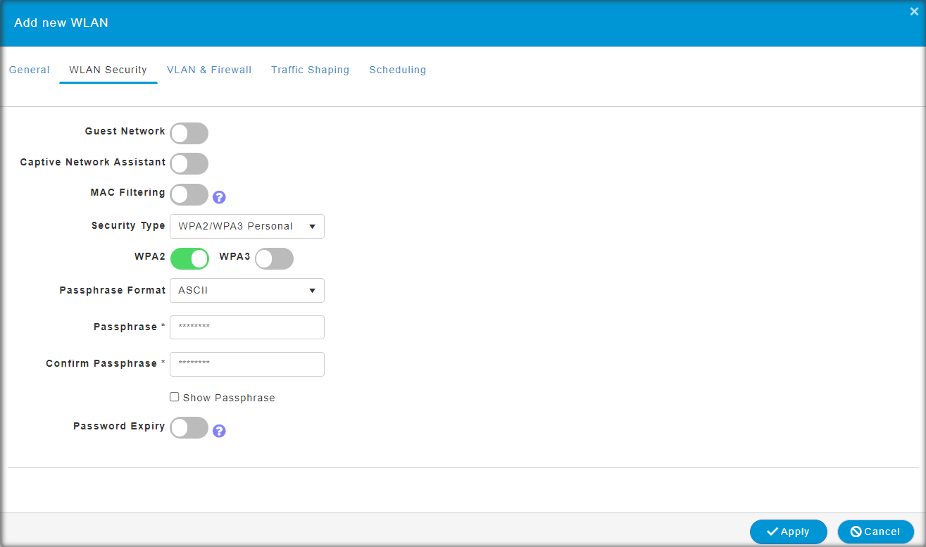
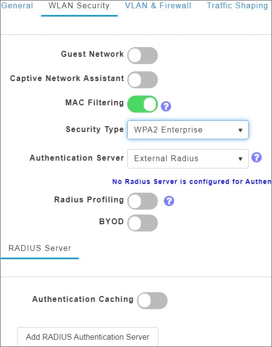
  • This option is available only for WPA2/WPA3 Personal WLAN with the WPA2 toggle button alone enabled, or WPA2 Enterprise enabled WLANs. By default, this option is Disabled.

    The 802.11r and WPA3 are not compatible with each other.

Over The DS

Click this button to enable or disable the fast roaming facility. By default, this is Disabled.

Reassociation Timeout(secs)

Enter the number of seconds after which the re-association attempt of a client to an AP should time out. The valid range is 1 to 100 seconds. The default is 20 seconds.

DTIM Period 802.11a/n (beacon intervals)

Depending on the timing set for your AP, it “buffers” broadcast and multicast data and let your mobile devices or clients know when to “wake up” to receive those data.

DTIM Period 802.11b/g/n (beacon intervals)

Depending on the timing set for your AP, it “buffers” broadcast and multicast data and let your mobile devices or clients know when to “wake up” to receive those data.

Client Band Select

Band selection enables client radios that are capable of dual-band (2.4 and 5GHz) operation to move to a less congested band.

Client Load Balancing

This feature can be used in order to load-balance clients across access points. Enabling this will improve client distribution on the wireless network.

You cannot configure the number of clients per AP.

Umbrella ProfileUmbrella ModeUmbrella DHC Override

For details on these options refer to Configuring Cisco Umbrella on Primary AP.

mDNSmDNS Profile

For details on these options refer to Mapping mDNS Profile to WLAN.

Multicast IP

Enter the Multicast IP group address. By default, the field will be null.

Multicast Direct

Enable the Multicast Direct toggle button to enhance the video streaming for wireless clients by converting multicast packets to unicast at CBW AP. By default, this is Disabled.

To enable this toggle, change the QoS value under the Traffic Shaping section to Gold or Platinum.

For details, see Media Steam.

802.11ax BSS Configuration

Down Link MU-MIMO

This toggle is used to enable/disable downlink (AP to Wireless Client) multi-user, multiple input, multiple output support for the WLAN. By default, this is Enabled.

Up Link MU-MIMO

This toggle is used to enable/disable uplink (Wireless Client to AP) multi-user, multiple input, multiple output support for the WLAN. By default, this is Enabled.

Down Link OFDMA

This toggle is used to enable/disable downlink (AP to Wireless Client) orthogonal frequency-division multiple access support for the WLAN. By default, this is Enabled.

Up Link OFDMA

This toggle is used to enable/disable uplink (Wireless Client to AP) orthogonal frequency-division multiple access support for the WLAN. By default, this is Enabled.

Configuring Scheduling

CBW supports an option to schedule availability for every WLAN. By default, all WLANs are available 24/7 when they are initially created. To schedule the WLAN availability, do the following:

  1. Navigate to Wireless Settings > WLANs > Add new WLAN > Scheduling.

  2. Schedule WLAN—You can choose one of the following options from the drop-down.

    • Enable—This enables scheduling for a chosen WLAN.

    • Disable—This disables scheduling for all the WLANs except the WLAN that is enabled.

    • No Schedule—Scheduling is not applied to the WLAN.


    Note


    You can also schedule the day/time for the WLAN to broadcast by enabling the corresponding Day and mention the start and end time using the slider.

    Enable the option Apply to all Weekdays to make changes for all the weekdays. By default, it is disabled.


  3. Click Apply to save the changes.

Enabling and Disabling WLANs

If for some reason you need to disable your WLAN or re-enable it, follow the steps below.

Procedure


Step 1

Navigate to Wireless Settings > WLANs.

Step 2

In the WLANs window, click the edit icon next to the WLAN you want to enable or disable.

Step 3

In the Edit WLAN window, under General select Enabled or Disabled.

Step 4

Click Apply.

Note

 
Clicking Apply after creating a new WLAN or editing an existing one always enables the WLAN irrespective of whether it was previously enabled or disabled.

Editing and Deleting WLANs

Procedure


Step 1

Choose Wireless Settings > WLANs.

Step 2

In the table of WLANs listed, perform one of the following actions as required:

  • Click the edit icon next to the WLAN you want to modify.

  • Click the delete icon next to the WLAN you want to delete.


Viewing and Managing WLAN Users

You can view and manage WLAN users only for WPA2 Enterprise and Guest WLAN with Local User Accounts as access types. To use your Cisco Business Wireless network, a wireless client should connect to a WLAN in the network. To connect to a WLAN, the wireless client will have to use the user credentials set for that WLAN. If this WLAN uses WPA2-Personal as a Security Policy, then the user must provide the appropriate WPA2-PSK set for that WLAN on the Primary AP. If the Security Policy is set to WPA2-Enterprise/Local User Account, the user must provide a valid user identity and the corresponding password

In the WLAN Users window, you can set up different users and their respective user credentials for the different WLANs in the CBW AP wireless network. These are local users authenticated by the Primary AP using WPA2-PSK.

To view and manage WLAN users, choose Wireless Settings > WLAN Users.

The WLAN Users window is displayed along with the total number of WLAN users configured on the Primary AP. It also lists all the WLAN users in the network along with the following details:

  • User name—Name of the WLAN user.

  • Guest user— Indicates a guest user account if the toggle button is enabled. This user account is provided with a limited validity of 86400 seconds (or 24 hours) from the time of its creation.

  • WLAN Profile—The WLANs that the user can connect to.

  • Password—The password to connect to a WLAN.

  • Description—Additional details or comments about the user.

Adding a WLAN User

To add a WLAN user, click Add WLAN User and specify the following details:

User name

Specify a name for the WLAN user account.

Guest user

Enable the slider button if this is meant to be a guest WLAN user account. You can also specify the validity of this account from the time of its creation, in seconds, in the Lifetime field. The default value is 86400 seconds (that is, 24 hours). You can specify a lifetime value from 60 to 31536000 seconds (that is, 1 minute to 1 year).

WLAN Profile

Select the WLAN that this user can connect to. From the drop-down list, choose a particular WLAN, or choose Any WLAN to apply this account for all WLANs set up on the Primary AP.

This drop-down list is populated with the WLANs which have been configured under Wireless Settings > WLANs.

For information on adding WLANs, see Adding and Modifying WLANs.

Password

The password to be used when connecting to a WLAN.

Description

Add any additional details or comments for the user.

Editing a WLAN User

To edit a WLAN user, click the edit icon next to the WLAN user whose details you want to modify and make the necessary changes.

Deleting a WLAN User

To delete a WLAN user, click the delete icon next to the WLAN user you want to delete and click OK in the confirmation dialog box.

Blocking and Unblocking Clients

  1. Navigate to Wireless Settings > WLAN Users > Local MAC Address.

  2. Click Add MAC Address.

  3. Enter the client MAC address.

  4. In the Type option, select the checkbox next to Allowlist or Blocklist to allow or deny this client joining your network.

    • Select Blocklist to deny the client from joining your network.


      Note


      Blocklisting a client or Mesh Extender that is currently joined to the network will not take effect until it attempts to rejoin the network (after disconnect or reboot).


    • Choose Allowlist to add the client. The MAC Filtering should be enabled on the WLAN to add your client MAC to the Local MAC address. This helps the client to join the network.

  5. Click Apply.

You can also import/export the Local MAC address list.

Social Login for Guest Users

This feature provides social login privileges for guest users that are connected using Google or Facebook accounts. To enable this option, follow the steps below on your AP.

Procedure


Step 1

Navigate to Wireless Settings > WLANs > Add new WLAN.

Step 2

Under the General tab, fill in the basic information for your WLAN. For details, see Adding and Modifying WLANs.

Step 3

Click the WLAN Security tab and set up the following details:

  • Select the Guest Network toggle button to turn it on

  • From the Access Type drop-down menu select Social Login.

  • Enable Facebook or Google, or both. If the Facebook toggle alone is enabled, guest users are authenticated using Facebook accounts

  • If the Google toggle alone is enabled, guest users are authenticated using Google accounts.

  • If both toggles are enabled, guest users are authenticated using Facebook or Google accounts

By default, both toggles are enabled.

Step 4

Click Apply to save the configuration.

Step 5

When the new WLAN is created with the access type Social Login, the Enable_Social_Login Pre-auth ACL is automatically mapped to the WLAN.

Note


You can also add and edit your URLs by navigating to Enable_Social_Login in Advanced > Security settings.

The Guest WLAN with an enabled Social login access type will be created. Once you connect to this guest WLAN you will be redirected to the default login page where you will find the login buttons for Google, or Facebook, or both depending on the toggle buttons enabled. Log in using the respective account and obtain the Internet access.


Personal PSK for Clients

This feature provides the flexibility of configuring a different PSK passphrase for clients connecting to the same WPA2 Personal WLAN with WPA2 policy enabled. CBW AP uses an AAA server to authenticate the client.


Note


This feature is not supported for WPA3 only WLANs.


To enable this feature, switch to Expert View and configure the following on the Primary AP:

Procedure


Step 1

Navigate to Wireless Settings > WLANs > Add new WLAN.

Step 2

Under the General tab, fill in the basic information for your WLAN. For more information see Adding and Modifying WLANs.

Step 3

Click the WLAN Security tab and specify the following details:

  1. Enable MAC Filtering toggle button.

  2. Under the Security Type drop-down list, select WPA2/WPA3 Personal.

  3. Click the WPA2 toggle button to turn it on.

  4. Select the Passphrase Format as either HEX or ASCII.

  5. Enter the Passphrase.

  6. Confirm the Passphrase. For more information see Adding and Modifying WLANs.

Step 4

Under the Radius Server tab, map the radius server detail using the following steps.

  1. Click Add RADIUS Authentication Server.

  2. Click Add RADIUS Accounting Server .

  3. Select the Radius Server IP address from the drop-down list.

  4. Click Apply.

After a successful MAC authentication, RADIUS Server will display the following Cisco AVPair attributes:

  • psk-mode – This contains the format of the Passphrase, it could be either ASCII, HEX, asciiEnc, or hexEnc.

  • psk – This contains the Passphrase configured for the client on the RADIUS Server

Note


The psk value could be a simple ASCII or HEX value or encrypted bytes in case of asciiEnc orhexEnc. The algorithm used for encryption or decryption is as per RFC2865 (user-password section – 16 bytes authenticator followed by encrypted key).

To configure radius server, navigate to Management > Admin Accounts > Radius (Expert View). For details, refer to Managing TACACS+ and RADIUS Servers

Step 5

Click the Authentication Caching toggle button.

  1. Enter the User Cache Timeout in minutes

  2. Enter theUser Cache Reuse if required.

By default, the User Cache Reuse is disabled. For more information see RADIUS Server table in Configuring the WLAN Security.

If Authentication caching is enabled, the PSK key is stored in the local cache along with the MAC Address and is used for subsequent authentications. The CBW AP first checks if any local DB is available for authenticating the client otherwise the request will be sent to Radius server for Authentication.

View the Auth cached clients at Management > Admin Accounts > Auth Cached Users (Expert View). For more information see Viewing Auth Cached Users

Step 6

Under the Advancedtab, click the AAA Override toggle button.

Step 7

Click Apply to save the WLAN updates.

Note

 
  • Devices with MAC addresses configured on Radius server will be able to connect to WLAN only with PSK passphrase configured on Radius server.

  • Devices with MAC addresses configured on Radius server will not be able to connect to WLAN with PSK configured on WLAN.

  • Devices with no MAC addresses configured on Radius server will be able to connect to WLAN with PSK configured on WLAN only. Navigate to Wireless Settings > WLAN Users > Local MAC Addresses and add the Client MAC in the Allowlist field. For more information see Blocking and Unblocking Clients.


Managing Associated Access Points

This section describes how to manage an assign roles to the AP in your network.

Navigate to Wireless Settings > Access Points.

In the Access Points Administration window, the number of APs associated with the CBW is displayed at the top of the window, along with the following details:

Manage

The following icons indicate whether the AP is acting as a Primary AP or Primary Capable AP or Mesh Extender.

Figure 1. Primary AP
Figure 2. Mesh Extender
Figure 3. Subordinate AP
Type

Specifies if the AP is Primary Capable or a Mesh Extender.

Location

The physical location of the AP.

Name

The assigned name of the AP.

IP Address

IP address of the AP.

AP MAC

The MAC address of the AP.

Up Time

Duration of how long the AP has been powered up.

AP Model

The model number of the AP.


Note


When an AP joins an AP group; or the RF profile of the AP group is changed, the AP rejoins the Primary AP. The AP will receive new configuration specific to the new AP group or RF profile.


Global AP Configuration

This allows you to configure a Native VLAN ID.

Procedure


Step 1

Navigate to Wireless Settings > Access Points.

Step 2

Click Global AP Configuration and configure the Native VLAN ID under the VLAN Tagging tab.

Step 3

Click Apply.


Administering Access Points

This section describes how to manage and define the APs in your network.

  1. Navigate to Wireless Settings > Access Points.

  2. In the Access Points window, click the edit icon next to the AP you want to manage.


    Note


    You can only administer those APs that are associated to the Primary AP.


General Tab

  1. In the Edit, under the General tab, you can edit the following AP parameters:

    Make me Primary AP

    This is available only for subordinate APs that are capable of participating in the Primary Election process. Click this button, to make it the Primary AP.

    IP Configuration

    Choose Obtain from DHCP to let the IP address of the AP be assigned by a DHCP server on the network.

    Choose to have a Static IP address. If you choose to have a static IP address, then you can edit the IP Address, Subnet Mask, and Gateway fields.

    AP Name

    Edit the name of the AP. This is a free text field.

    Location

    Edit a location for the AP. This is a free text field.

    Set as Preferred Primary

    Select this to make the AP the preferred Primary.

    Note


    Setting as Preferred Primary will not change the current network status. In other words, it will not force the AP to take over as Primary, but it will take effect next time the network reboots.

The following parameters are also displayed under the General tab, but can not be edited.

Operating Mode

Displays the operating Mode of the AP.

AP MAC address

Displays the AP MAC address.

AP Model

Displays the AP Model number.

IP Address

IP Address of the Access Point.

This field is non-editable only if Obtain from DHCP has been selected.

Subnet Mask

Subnet mask address.

This field is non-editable only if Obtain from DHCP has been selected.

Gateway

Gateway address.

This field is non-editable only if Obtain from DHCP has been selected.

Primary Tab

For the Primary AP, you can manually edit the following parameters under the Primary tab.

Primary AP Name

You can edit the Primary AP Name set during the initial configuration using the Setup Wizard.

IP configuration

You can configure either Static IP or obtain from DHCP.

IP Address

This IP address can be used in the Login URL to access the Primary AP's web interface.

The URL is in the format http://<ip addr> or https://<ip addr>. If you change this IP address, the login URL also changes.

Subnet Mask

Subnet mask of the network.

IP Address, Subnet Mask and Gateway fields are editable only if Static IP Address is selected.

VRID

Virtual Router Identifier, is a unique number used to identify a virtual router.

By default, the value of VRID is 1 and the configurable range is between 1-255. This option is available only in Expert View.

Change the VRID only if a VRID conflict is detected in the network. To check if there are any VRID conflicts, go to Advanced > Logging. In the Logs window, the following message will be logged in Errors (3) level: "%CNFGR-3-VRRP_CONFLICT_DETECTED: cnfgr.c:4856 VRRP group conflict detected with VRID <vrid number>! Configure new VRID value under Wireless Settings > Access Points > Edit AP > Primary AP in Expert View"

Country Code

Select the country for your Primary AP. It is not advisable to change the country code unless you have not configured the correct country in the initial setup wizard.

Changing a country code turns the radio down until the Primary AP is rebooted.

Radio 1 and Radio 2 Tabs

You can set the following parameters under the Radio 1 and Radio 2 tabs.


Note


The Radio 1 tab corresponds to the 2.4GHz (802.11 b/g/n/ax) radio on all APs. The Radio 2 tab corresponds to only the 5GHz (802.11 a/n/ac/ax) radio on all APs.

The radio tab name also indicates the operational radio band within brackets.


Table 1. Radio 1 (2.4GHz)

2.4 GHz Channel

Enable or Disable the corresponding radio on the AP.

For 2.4GHz radio, you can set this to Automatic, or set a value from 1 to 11.

Selecting Automatic enables Dynamic Channel Assignment. This means that channels are dynamically assigned to each AP, under the control of the Primary AP. This prevents neighboring APs from broadcasting over the same channel and prevents interference and other communication problems. For the 2.4GHz radio, 11 channels are offered in the U.S. and up to 14 in other parts of the world. However, only 1-6-11 can be considered non-overlapping if they are used by neighboring APs.

Assigning a specific value statically assigns a channel to that AP.

The channel width for 2.4GHz can only be 20MHz.

Table 2. Radio 2 (5GHz)

5 GHz Channel

For 5GHz radio, you can set this to Automatic, 36, 40, 44, 48, 52, 56, 60, 64, 100, 104, 108, 112, 116, 132, 136, 140, 149, 153, 157, 161, or 165. Up to 23 non-overlapping channels are offered.

Assigning a specific value statically assigns a channel to that AP. DFS channels are indicated with "(DFS)" tag along with the channel number in the drop-down list.

For Mesh backhaul Radio, the Automatic option is not supported in Mesh mode.

5 GHz Channel Width

The channel width for 5GHz can be set to Automatic, or to 20, 40, or 80MHz, if channel bonding is used. By default, it is set to 80MHz.

Channel bonding groups the channels by 2 or 4 for a single radio stream. This increases the speed and the throughput. Because the number of channels is insufficient in 2.4 GHz, channel bonding cannot be used to enable multiple non-overlapping channels.

Table 3. Radio 1 and Radio 2

Transmit Power

You can set it to Automatic, or provide a value ranging from 100, 75, 50, 25, 12 (in terms of percentages).

By default, it is set to 100% (maximum power).

Selecting Automatic adjusts the radio transmitter output power based on the varying signal level at the receiver. This allows the transmitter to operate at less than maximum power for most of the time; when fading conditions occur, transmit power will be increased as required until the maximum is reached.

For Mesh backhaul Radio, the Automatic option is not supported in Mesh mode.

Nations apply their own RF emission regulations to the allowable channels, allowed users and maximum power levels within these frequency ranges. As per the regulatory rules, the DFS channels (52 – 144) have low TX power levels compared to non-DFS channels (36-48, 149-165).

Please choose the non DFS channel for maximizing the coverage.

In Mesh Mode navigate to: Wireless Settings > Access Points and click the edit icon at the left end of the row, then select Radio 2 and Channel.

In Non-mesh mode: (in Expert view) navigate to: Advanced > RF Optimization > Select DCA channels > 5Ghz then unselect the DFS channel numbers.

Interferer Detection

Enable this option to identify the non Wi-Fi devices.

Ensure that you enable the Interferer detection globally under Advanced > RF Optimization (in Expert View).

BSS Color Configuration

This drop-down is used to set BSS Color Configuration as Global or Custom. By default, this is Global.

  • Global- Global BSS Color Configuration set in Advanced > RF Optimization (in Expert View) will be considered

  • Custom - Selecting Custom will show up as "BSS Color Status".

BSS Color Status

The toggle is used to enable/disable per AP Radio's BSS Color Status. By default, this is disabled.

The "BSS Color" text box will appear when the BSS Color Status toggle is enabled.

BSS Color

The text box is used to set the Custom BSS Color value for the AP Radio and it can be assigned a value from 1 to 63. By default, the value is 1.


Note


The channels in both the radios will change according to the country configured in the Primary AP.


When you are done with all your changes click Apply to save and exit.


Note


For details on the Mesh tab, see Mesh Network Components.


Access Point Groups

By creating Access Point Groups you can control which SSIDs can be pushed to each AP group. Each access point advertises the enabled WLANs that belong to its access point group. The access point does not advertise disabled WLANs in its access point group or WLANs that belong to another group.

By default, there is a AP Group called default-group created on your Primary AP and all the WLANs are mapped to this default group. All the access points are also mapped to this default-group. This means, WLAN (ID 1-16) will be available in any of the APs belonging to the default group.


Note


Any AP or Mesh extender added to the network is mapped to the default-group. If required, you can create your own AP group and map the AP to the same.

For Mesh deployments, ensure both the Root AP and Mesh AP are mapped to the same Access Point Group.


To configure this, do the following:

  1. Switch to Expert View by clicking the bi-directional icon on the top right of the Primary AP UI.

  2. Navigate to Wireless Settings > Access Points Groups > Add New Group.

  3. In the General tab, provide an AP Group Name and a description for your reference.

  4. In the WLANs tab, select the WLAN that you want to push to the group.

  5. In the Access Points tab, push the access point to the group that you created such that the WLANs is advertised in only those particular APs.

  6. Click Apply.

Setting a Login Page for WLAN Guest Users

Follow these steps to provide guest users with access to your network.

Procedure


Step 1

Set up a new WLAN or decide on an existing WLAN, to which you will provide access for guest users.

You can specifically set up a WLAN exclusively for guest access. This is done by setting the WLAN Security as Guest for that WLAN. For more information, see Adding and Modifying WLANs.

Step 2

Set up a guest user account. Go to Wireless Settings > WLAN Users, and set up an account with the Guest User check box selected. For more information, see Viewing and Managing WLAN Users.

You can provide the Guest Users of your WLAN with one of the following login page options:


Setting the Default Login Page

Right out of the box, the default login page contains a Cisco logo and Cisco-specific text. You can choose to modify this default login page as described here.

Procedure


Step 1

Navigate to Wireless Settings > Guest WLAN.

Step 2

In the Guest WLANs page, the number of Guest WLANs currently set up in the network is displayed at the top of the page.

Step 3

Choose the Internal (Default) login page in the Page Type drop-down list.

Step 4

Set the following parameters to modify the default internal login page:

  • Display Cisco Logo—This field is set to Yes by default. To hide the Cisco logo that appears at the top-right corner of the default window, choose No. However, you do not have an option to display any other logo.

    Navigate to Apply > Previewto preview the changes.

  • Redirect URL After Login— To have guest users redirected to a particular URL (such as the URL for your company) after login, enter the URL in this field. You can enter up to 254 characters.

  • Page Headline—The default headline is Welcome to the Cisco Business Wireless. To create your own headline on the login page, enter the desired text in this field. You can enter up to 127 characters.

  • Page Message— The default message is displayed: Cisco is pleased to provide the Wireless LAN infrastructure for your network. Please login and put your unified wireless solution to work.. To create your own message on the login page, enter the desired text in this field, You can enter up to 2047 characters.

Step 5

Click Apply.


Setting a Customized Login Page

You can create a custom login page on a computer, compress the page and image files into a .TAR file, and then upload it to the Primary AP. The upload is done via HTTP.


Note


When you save the Primary AP's configuration, it does not include extra files or components, such as the web authentication bundle, that you download and store on your Primary AP. So always manually save external backup copies of such files.


Note


Cisco TAC is not responsible for creating a custom web authentication bundle.


Before you begin

To create a custom login page on a computer make sure of the following:

  • Name the login page login.html. The Primary AP prepares the web authentication URL based on this name. If the server does not find this file after the web authentication bundle has been untarred, the bundle is discarded, and an error message appears.

  • The page should not contain more than 5 elements (including HTML, CSS, and Images). This is because the internal Primary AP web server implements a DoS protection mechanism that limits each client to open a maximum of 5 (five) concurrent TCP connections depending on the load. Some browsers may try to open more than 5 TCP sessions at the same time if the page contains more elements and this may result in the page loading slowly depending on how the browser handles the DoS protection.

  • Include input text boxes for the username and the password.

  • Extract and set the action URL in the page from the original URL.

  • Include scripts to decode the return status code.

  • All paths used in the main page (images, for example) are of relative type.

  • No file names within the bundle are longer than 30 characters.

Compress the page and image files into a .TAR file. The maximum allowed size of the files in their uncompressed state is 1 MB.

Cisco recommends that you use an application that complies with GNU standards to compress the.TAR file (also referred to as the web authentication bundle.). If you load a web authentication bundle with a .TAR compression application that is not GNU compliant, the Primary AP will not be able to extract the files in the bundle.

The .TAR file enters the Primary AP’s file system as an untarred file.


Note


If you have a complex customized web authentication bundle which does not comply with the aforementioned prerequisites, then Cisco recommends that you host it on an external web server.


Procedure


Step 1

Navigate to Wireless Settings > Guest WLAN.

The Guest WLANs page is displayed. The number of Guest WLANs currently set up in the network is displayed at the top of the page.

Step 2

To upload a customized login page into the Primary AP, in the Page Type drop-down list, choose Customized.

Step 3

Click Upload and browse to upload the .TAR file of the customized web authentication bundle. While uploading the .TAR file, the status of file upload is displayed on the same page.

Step 4

If you want the user to be directed to a particular URL (such as the URL for your company) after login, enter that URL in the Redirect URL After Login text box. You can enter up to 254 characters.

Step 5

Click Apply.

Click Preview to view your customized web authentication login page.


About Cisco Mesh

Cisco Mesh introduces a new paradigm of wireless internet access by providing high data rate service and reliability. It is also a solution to reduce the complexity of wiring between each devices in a network. For a stable network establishment, there must be a wireless interacting medium between each APs.

CBW indoor mesh brings these values to you:

  • Not having to run Ethernet wiring to each AP.

  • Network connectivity where wires cannot provide connectivity.

  • Easy to deploy and provide flexibility in deployment.

This chapter summarizes the design details for deploying a Cisco Mesh Extender for indoor environments. The indoor wireless access takes advantage of the growing popularity of inexpensive Wi-Fi clients, enabling new service opportunities and applications that improve user productivity and responsiveness.

Adding a Mesh Extender

For details refer to Adding Mesh Extenders.

Convert Non-Mesh to Mesh Deployment

For maintaining, the mesh state between the APs there must be a communication establishment between them and this takes place through the backhaul radio (2.4GHz or 5GHz – user configurable). To configure the mesh mode in the Primary AP, do the following:

Procedure


Step 1

Navigate to Wireless Settings > Mesh.

Step 2

Enable the Mesh toggle button, and click Apply.

Step 3

The entire network will operate in the Mesh mode after the Primary AP reboots.

Step 4

Add the MAC address of the Mesh Extenders in the auth-list that you wish to join the network.

Note


For details refer, Adding Mesh Extenders.

For the wired access points (CBW150AX) the MAC address will be added automatically in the Local MAC Address table, provided they exist in the same network.

Step 5

The automatic entry of the physical address of the wired AP can be verified by knowing its last few digits in the MAC address.

For example, when a CBW150AX has joined the Primary AP, its MAC address will be displayed in the Local MAC Address table with its corresponding description as (CBW150AX-0d6c). Here, 0d6c is the ending digits of its MAC address F0:1D:2D:9E:0D:6C.

Step 6

Wait for few minutes and navigate to Wireless Settings>Access Points.

Step 7

Check if the Access Point has joined the Primary AP.


Mesh Network Components

Navigate to Wireless Settings > Access Points > Edit Access point. The following options are available under the Mesh tab.

AP Role

By default, the Primary/Primary Capable AP role is set to Root and the mesh extenders role is set to Mesh. You can configure the AP Role for Primary Capable APs from Root/Mesh to Mesh/Root. This option is configurable in Expert View. After changing the AP Role, the Primary Capable AP will reload and join the Primary AP.

To check the AP role and type, navigate to Wireless Settings > Access Points.

If the Primary Capable AP role is changed from Root to Mesh, the type will be displayed as Mesh Extender. The AP will join as a Wired Mesh Extender if a wired uplink is present. If not present, the AP will join as Wireless Mesh Extender. In either case, the functionality of Mesh Extender remains the same.

If the Primary Capable AP role is changed from Mesh to Root, the Type will be displayed as Primary Capable.

  • Only Primary Capable APs (CBW150AX) are allowed to change the AP role.

  • Primary Capable APs that are operating with AP Role as Mesh, will not be considered for Primary AP selection.

Bridge Type

By default, it is set as indoor.

Bridge Group Name

Bridge group names (BGNs) control the association of mesh access points. BGNs can logically group radios to avoid two networks on the same channel from communicating with each other. The setting is also useful if you have more than one Primary Capable AP in your network in the same sector (area). Default BGN is set with first 10 character of the configured SSID during initial setup wizard. This option is available in Expert View.

Exercise caution when you configure a BGN on a live network. Always start a BGN assignment from the farthest-most node (last node, bottom of mesh tree) and move up toward the RAP to ensure that no mesh access points are dropped due to old and new BGNs mixed within the same network.

Strict Matching BGN

When Strict Match BGN is enabled on the mesh AP, it will scan ten times to find the matched BGN parent. After ten scans, if the AP does not find the parent with matched BGN, it will connect to the non-matched BGN and maintain the connection for 15 minutes. After 15 minutes, the AP will again scan ten times and this cycle continues. The default BGN functionality remains the same when Strict Match BGN is enabled. By default, it is disabled. This option is available in Expert View.

Backhaul Interface

This displays the type of interface. It can be either 802.11a/n/ac if Mesh Backhaul Slot is 5GHz and 802.11b/g, if Mesh Backhaul Slot is 2.4GHz.

Install Mapping on Radio Backhaul

This option helps to broadcast the SSIDs in backhaul radio such that the client can join the AP using the backhaul radio. By default it is Enabled. If you experience Mesh performance or stability issues, you can disable this option to avoid wireless clients joining the backhaul radio.

Mesh Backhaul Slot

The communication between each APs are carried over a particular radio and you can configure it in either 5GHz or 2.4GHz. By default, it is in 5GHz mode.

The Backhaul interface configuration done under Wireless Settings > Mesh > Mesh Backhaul Slot is the global configuration. If you want to override it for selected Access Points, you can change the Backhaul interface configuration by navigating to Wireless Settings > Access Points (Edit) > Mesh > Mesh Backhaul Slot.

Preferred Parent

This has to be computed from the Radio MAC of the Primary Capable AP which you would like to set as preferred parent your Mesh AP. We need to add 11 in hex to last two bytes of the Preferred Parent’s radio MAC. To obtain the Radio MAC of the Primary Capable AP, go to Monitoring > Access Points, and the view the AP details by selecting the AP you want. Note down the Radio MAC (xx:xx:xx:xx:xx:yy) and compute the value to be set in Preferred Parent field. Refer the table below for sample computation.

This field is present only in the Mesh Extender Mesh tab.

Before (yy) After adding (+11) (yy')

20

31

40

51

60

71

80

91

A0

B1

C0

D1

E0

F1

Ethernet Bridging

Use this feature to access the Internet by connecting a wired client to the LAN ports of the APs in the Mesh network. By default, it is Enabled.

A Primary Capable AP (CBW150AX) in Mesh mode with wireless backhaul connected to a power injector supports Ethernet bridging.

  1. Connect the AP output port of the Power injector to the primary capable AP in mesh mode.

  2. Connect the wired client to the other port in Power injector.

  3. Check if you are able to access the Internet.

  4. In the Mesh mode, the wired client connected to LAN ports will not be displayed in the Primary AP UI.

Note


The wired client connected to the Ethernet port of the Primary Capable AP in Mesh mode with wireless backhaul will obtain the IP address in the AP VLAN.

Changing Mesh Parameters

Following are the several mesh configurations that are available in the Primary AP UI under Wireless Settings > Mesh.

Backhaul Client Access

When Backhaul Client Access is enabled, it allows wireless client association over the backhaul radio. The backhaul radio is a 5GHz radio for most of the Cisco Access Points. This means that a backhaul radio can carry both backhaul and client traffic.

When Backhaul Client Access is disabled, only backhaul traffic is sent over the backhaul radio and client association is over the second radio. By default, this option is Enabled.

Mesh Backhaul Radio Resource Management

The Radio Resource Management (RRM) software embedded in the Primary AP acts as a built-in RF engineer to consistently provide real-time RF management of your wireless network. RRM enables the Primary AP to continually monitor their associated lightweight access points for information on traffic load, interference, noise, coverage and other nearby APs.

The RRM measurement in the mesh AP backhaul is enabled, if the wired Root AP has Ethernet uplink and there is no Mesh Extender joined to it.

Mesh Backhaul Slot


Note


The Backhaul interface configuration done under Wireless Settings > Mesh > Mesh Backhaul Slot is the global configuration. If you want to override it for selected Access Points, you can change the Backhaul interface configuration by navigating to Wireless Settings > Access Points > (Edit) > Mesh > Mesh Backhaul Slot.


In certain countries, Mesh Network with 5GHz backhaul network is not allowed to use. Even in countries which is permitted with 5GHz, customers may prefer to use 2.4GHz radio frequencies to achieve much larger Mesh or Bridge distances.

When a Primary AP downlink backhaul is changed from 5GHz to 2.4GHz or from 2.4GHz to 5GHz, that selection gets propagated from Primary AP to all the Subordinate APs and they will disconnect from the previously configured channel to get reconnected to another channel. To do this, follow the instructions below:

Procedure

Step 1

Navigate to Wireless Settings > Mesh > Mesh Backhaul Slot.

Step 2

Select the backhaul radio (either 5GHz or 2.4GHz) in the Primary AP to push the configuration to its subordinate APs and have a better mesh coverage.

Note


Only Primary Capable APs are configured with the backhaul frequency of 5GHz or 2.4GHz. Once the AP is configured, the same frequency selection will propagate down the branch to all the Subordinate APs.


VLAN Transparent

This feature determines how a mesh access point handles VLAN tags for Ethernet bridged traffic. If VLAN Transparent is enabled, then VLAN tags are not handled and packets are bridged as untagged packets.

To enable the VLAN Transparent, follow the steps below:

Procedure

Step 1

Navigate to Wireless Settings > Mesh > Ethernet bridging.

Step 2

Enable VLAN Transparent.