Using the Voice Services Provisioning Tool to Provision a Cisco Media Gateway Controller
Available Languages
Table Of Contents
Using the Voice Services Provisioning Tool to Provision a Cisco Media Gateway Controller
Adding Ethernet Cards and Interfaces
Configuring SS7 Signaling Services
Adding and Changing Linkset Properties
Add SS7 Subsystems (Mated Pairs)
Add or Modify FASPath properties
Configuring Media Gateway Control Links
Adding a Broadband or Narrowband Service Card
Adding an IPFAS Signaling Service
Changing IPFAS Signaling Service Properties
Adding an MGCP Signaling Service
Adding and Changing MGCP Signaling Service Properties
Importing Trunk Groups and Trunks
Deleting Trunks from a Trunk Group
Adding Route Groups and Routes
Hierarchical View of Provisioned Components
Checking Integrity for MGC Signaling Configuration
Checking Traffic Against MGC Configuration
Viewing Generated Cisco MGW Commands
Check Status of Backup or Restore
Provisioning the Billing and Measurements Server
Starting a BAMS Provisioning Session
Provisioning General Information
Provisioning Trunk Group Information
Using the Voice Services Provisioning Tool to Provision a Cisco Media Gateway Controller
This chapter shows you how to use version 1.6.X of the Voice Services Provisioning Tool (VSPT) to provision a Cisco Media Gateway Controller (MGC).
Depending on the VSPT software version you are using, the screens you see may not appear exactly as the screen examples in this chapter.

Tip
Before you begin provisioning, you should have a list of components you want to provision, including the component names, IP addresses, properties, and other parameters. These can be created using the worksheets provided in "Planning Worksheets." In addition, descriptions of the properties and values contained in the VSPT are included in "Components and Properties," and in this chapter. You should review this information before you begin provisioning and keep it available to refer to during provisioning.
Provisioning a Cisco MGC is a complex process that can be logically divided into the following steps:
•
•
•
•
The provisioning procedures described in this chapter follow the sequence for provisioning a "typical" Cisco MGC configuration.

Note
This chapter shows how to use version 1.6 of the VSPT to provision a typical Cisco Media Gateway Controller (MGC) and contains the following sections:
•
•
Configuring the Cisco MGC
To provision a Cisco MGC, configure the following basic network elements:
•
•
•
Adding an MGC Host
The Cisco MGC host is a Sun workstation running the Cisco MGC software. Table 4-1 lists the MGC host properties. Use the information in the table to add an MGC host (and a standby host, if you are configuring a redundant MGC).
Perform the following steps to add an MGC host and a standby host, if applicable. Where necessary, refer to Table 4-1 for property values.
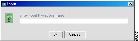
Step 1
Figure 4-1 Name Configuration
Step 2
Step 3
Step 4
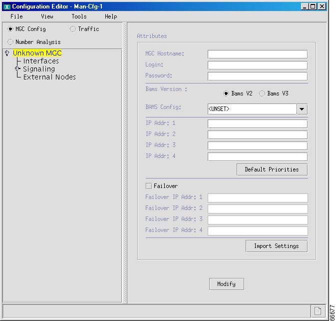
Figure 4-2 Adding a Cisco MGC Host
Step 5
Step 6
Step 7
Note
Step 8
Step 9
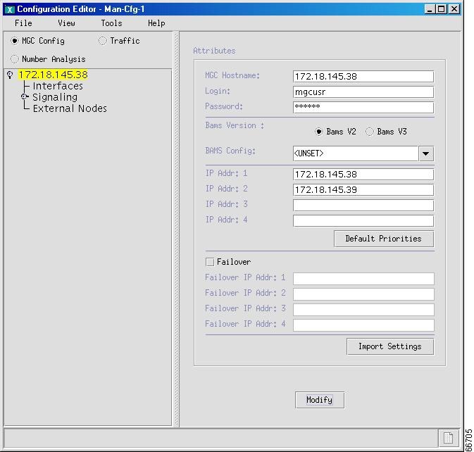
Click Modify. The hierarchical tree displaying "Unknown MGC" changes to the MGC host name you entered in Step 5, (see Figure 4-3), and "Modification complete"
is displayed briefly on the bottom left section of the screen.
Figure 4-3 MGC Host Added
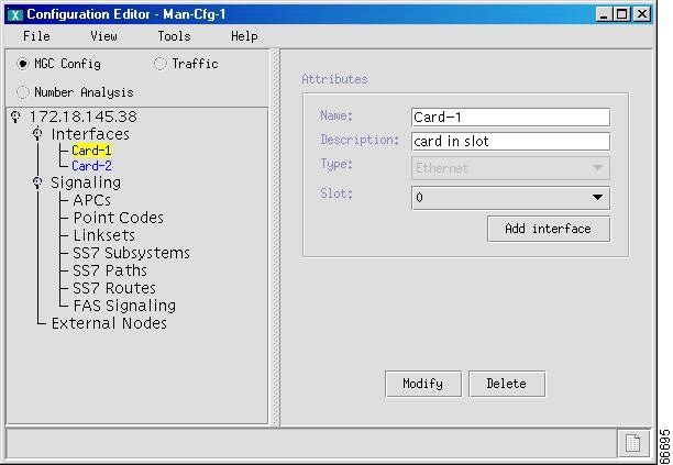
Adding Ethernet Cards and Interfaces
Interfaces components identify connections to the network Ethernet cards or adapters installed in the Cisco MGC host. They permit IP communication between the Cisco MGC and the Cisco SLTs.
Table 4-2 lists interface properties. Use the values in the table as you add interfaces to your MGC.
Perform the following steps to add an Ethernet interface to the Cisco MGC. If necessary, refer to Table 4-2 for property values.
Step 1
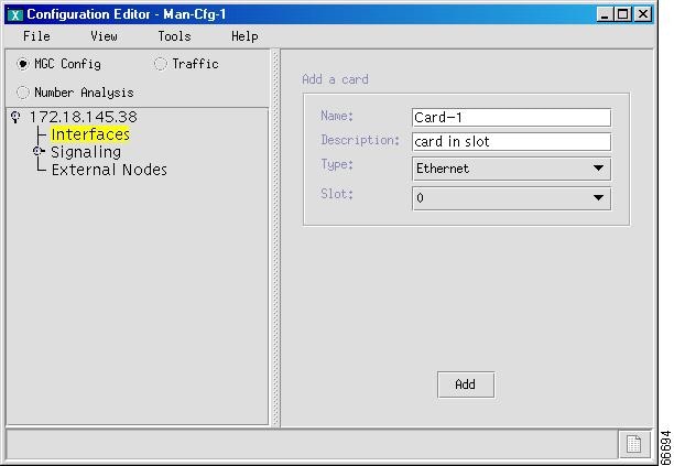
Figure 4-4 Adding Interface Cards
Step 2
Step 3
Step 4
Step 5
Step 6
Step 7
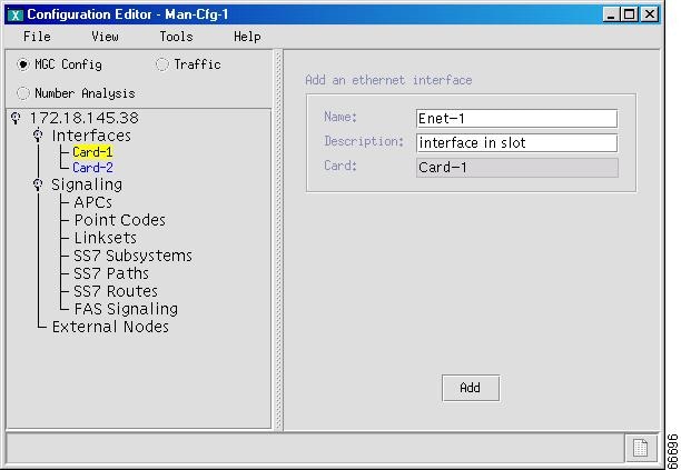
Figure 4-5
Adding an Interface
Step 8
Figure 4-6 Interface Parameters
Step 9
Step 10
Step 11
Step 12
Step 13
Configuring SS7 Signaling Services
SS7 signaling services identify all signaling types processed by the Cisco MGC. To configure SS7 signaling services, you must:
•
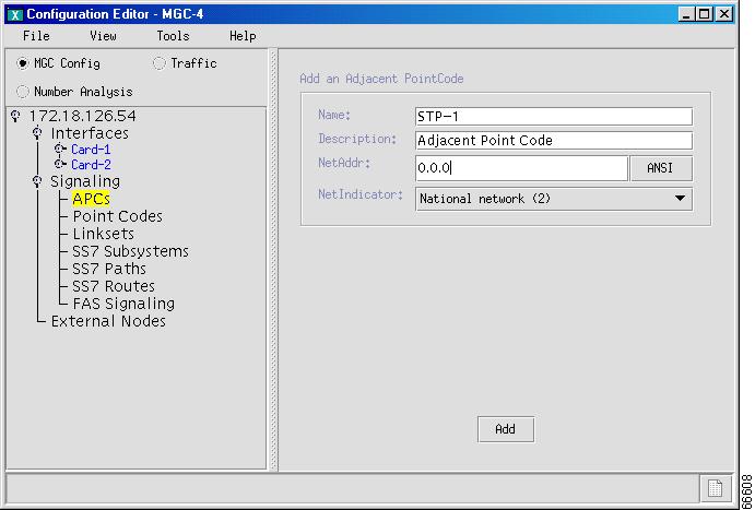
Adding Adjacent Point Codes
Adjacent point codes (APCs) are the SS7 network addresses of the STPs (or SSP directly connected to the SLT) that connect to the MGC node. The MGC node communicates with external SSPs and SCPs through an STP.
Table 4-3 lists the APC properties. Use the values in the table as you add APCs to the Cisco MGC.
Use the following procedure to add the APCs for STPs. Where necessary, refer to Table 4-3 for property values.
Step 1
Figure 4-7 Adding Adjacent Point Codes
Step 2
Step 3
Step 4
Step 5
•
•
•
•
Step 6
Step 7
Add Point Codes
Every signaling point in the SS7 network is identified by a unique point code. Provision point codes using the following subsections:
Note
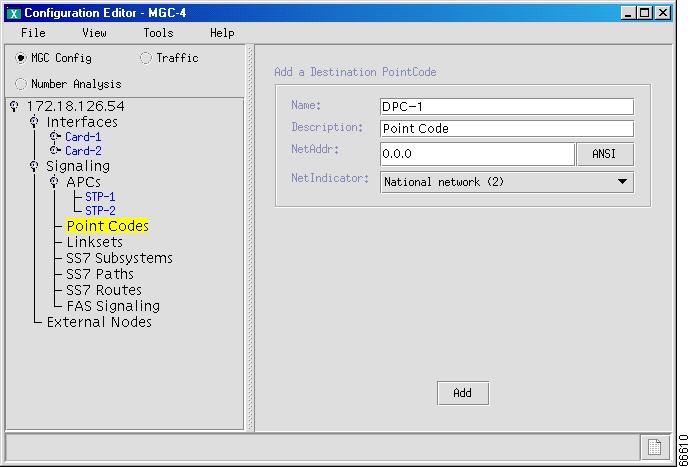
Add Destination Point Codes
A destination point code (DPC) is an SS7 network address that identifies an SS7 network node, such as an STP, SSP, or media gateway, with which the MGC node communicates.
Use the following procedure to add the DPCs for the ILEC and CLEC switches:
Step 1
Figure 4-8 Adding DPC
Step 2
Step 3
Step 4
Step 5
•
•
•
•
Step 6
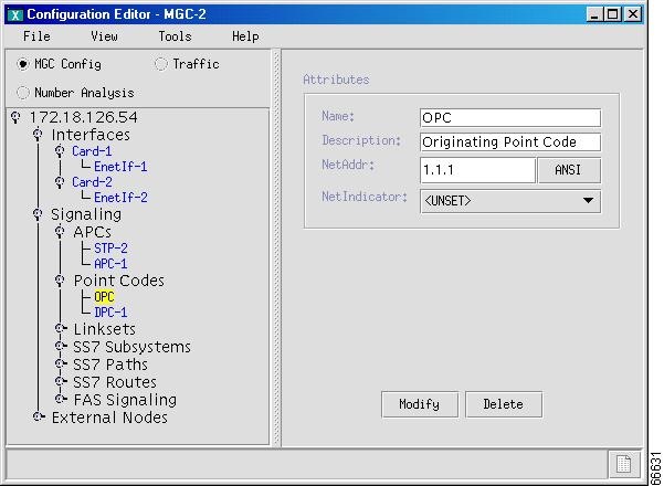
Add Origination Point Code
The origination point code (OPC) is an SS7 network address that identifies a Cisco MGC. Use the following procedure to configure the OPCs for the Cisco MGC:
Step 1
Figure 4-9 Add OPC
Step 2
Step 3
Step 4
Step 5
•
•
•
•
Step 6
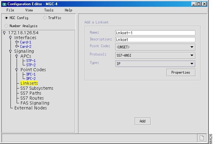
Add Linksets
A linkset is a logical group of links that transport SS7 signals to the Cisco MGC. Linksets can consist of the following:
•
•
Table 4-4 lists linkset properties. Use the values in the table as you add linksets to your MGC.
Use the following procedure to add the linksets between the MGC node and the STPs. Where necessary, refer to Table 4-4 for property values:
Step 1
Figure 4-10 Adding Linksets
Step 2
Step 3
Step 4
Step 5
•
•
•
•
•
Step 6
Step 7
Note
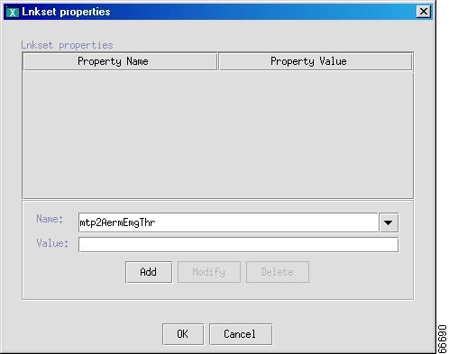
Adding and Changing Linkset Properties
You can add and change the properties of a linkset after it is created, including message and timer values. Changes apply to all linksets you create. You do not have to change the default properties. For a list of linkset properties, default values, and descriptions, see the Cisco Media Gateway Controller Software Release 7 Provisioning Guide.
Perform the following steps to add or change linkset properties:
Step 1
Figure 4-11 Adding and Changing Linkset Properties
Step 2
Figure 4-12 Linkset Property Added
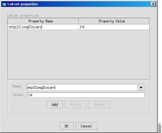
Step 3
Step 4
Step 5
Step 6
Note
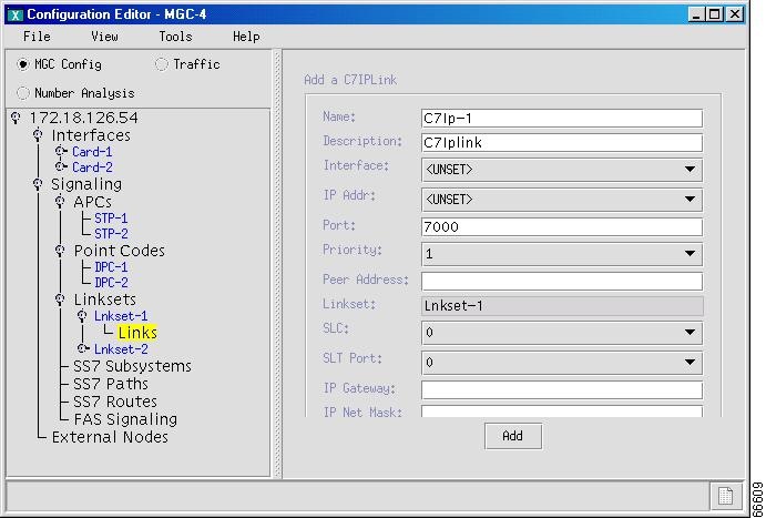
Add C7 IP Links
You must configure links for all physical connections bearing signals that enter and exit the Cisco MGC. This includes SS7 signals from the SSP (ILEC switch) and signal links to the media gateway.
A C7 IP link component identifies one link within a linkset that enters the Cisco MGC through an SLT. Table 4-5 lists the C7 IP link properties. Use the values in the table as you add links to linksets.
Add a C7 IP link for each physical SS7 link that is connected to the SS7 network through the Cisco SLT. Each link corresponds to a linksets you created in the "Add Linksets" section.
Use the following procedure to add C7 IP links. Where necessary, refer to Table 4-5 for property values.
Step 1
Figure 4-13 Adding C7 IP Links
Step 2
Step 3
Step 4
Step 5
•
•
•
•
Note
Step 6
Step 7
Note
Step 8
Note
Step 9
Step 10
Step 11
Note
Step 12
Step 13
Step 14
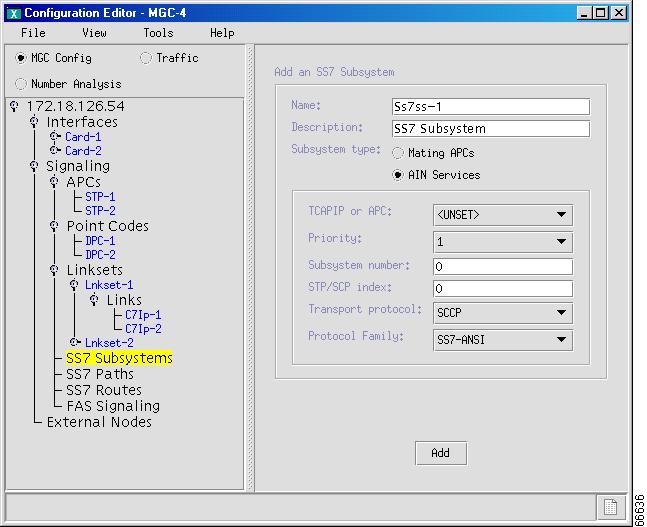
Add SS7 Subsystems (Mated Pairs)
An SS7 subsystem allows the Cisco MGC to route traffic over the C-links between mated STPs to provide network reliability. The links to these STPs are defined in the "Add Linksets" section.
The SS7 subsystem provides local number portability (LNP) support through an SCP. Because the SS7 subsystem is an instance of an application, you need to configure a subsystem for each application type of service (for example, LNP). The SS7 subsystem is also used to connect an STP to an SCP database for AIN queries. In this case, there is no mated STP.
Table 4-6 lists SS7 subsystem properties. Use the values in the table as you add SS7 subsystems to your MGC.
Use the following procedure to add SS7 subsystems for the STPs. Where necessary, refer to Table 4-6 for property values.
Step 1
Figure 4-14 Adding Mated pairs
Step 2
Step 3
Step 4
Figure 4-15 Configure Mated Subsystem
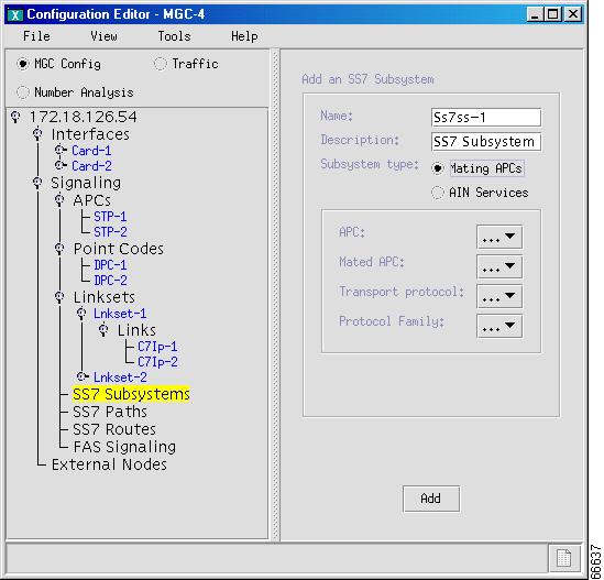
Step 5
Step 6
Step 7
Step 8
Step 9
Step 10
•
•
•
•
•
Note
Step 11
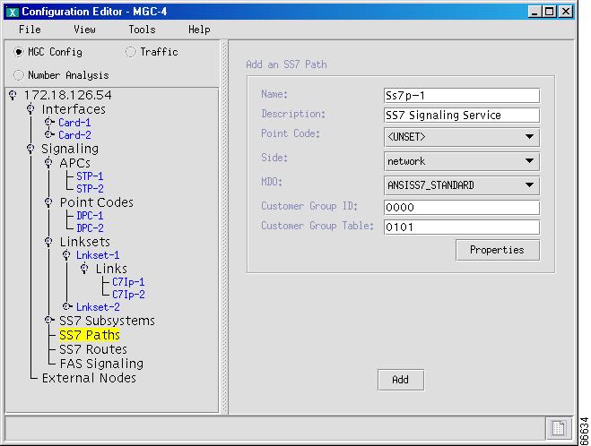
Configure SS7 Paths
An SS7 signaling service identifies the path over which the MGC node communicates, using a specific protocol, with a remote MGC or switch. The MML component name is SS7PATH. Table 4-7 lists the SS7 signaling service properties. Use the values in the table as you add SS7 paths to your MGC.
Use the following procedure to add SS7 signaling service paths to the switch (identified by the DPC). If you have a signaling service from the Cisco MGC to a PSTN switch, use the SS7 path component to add the service to your configuration. Where necessary, refer to Table 4-7 for property values.
Step 1
Figure 4-16 Adding SS7 Paths
Step 2
Step 3
Step 4
•
•
Step 5
Step 6
Step 7
Step 8
Step 9
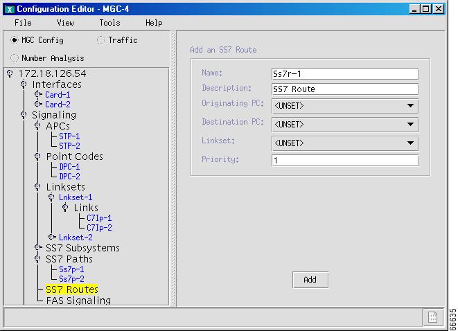
Configure SS7 Routes
An SS7 route is a path, through a linkset, between one MGC node and another MGC node or a switch. In the following example, the SS7 routes indicate the linksets that carry SS7 signals between the MGC node and the ILEC Class 5 switch or CLEC Class 5 switch.
You must define a separate route for each remote switch.
Table 4-8 lists the SS7 route properties. Use the values in the table as you add SS7 routes to your MGC.
You must add an SS7 route for each signaling path from the Cisco MGC to the PSTN switch through the linksets you have created to the STPs. You should create two routes to the PSTN switch, with each route passing through a different STP of a mated pair.
Use the following procedure to add SS7 routes to the MGC. Where necessary, refer to Table 4-8 for property values.
Step 1
Figure 4-17 Adding SS7 Routes
Step 2
Step 3
Step 4
Step 5
Step 6
Step 7
Note
Step 8
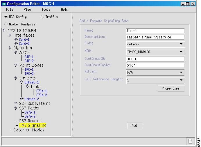
Configure FAS Signaling
A facility associated signaling (FAS) service uses the same path for signaling and voice circuits. Table 4-9 lists the FAS signaling service properties. Use the values in the table as you add FAS signaling services to your MGC.
Use the following procedure to configure FAS signaling for the Cisco MGC. Where necessary, refer to Table 4-9 for property values.
Step 1
Figure 4-18 Add FAS Signaling
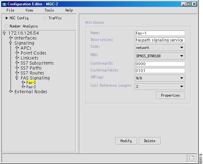
Step 2
Figure 4-19 Configure FAS Signaling
Step 3
Step 4
Step 5
•
•
Step 6
Step 7
Step 8
Step 9
Step 10
Step 11
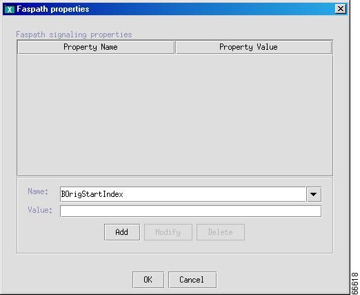
Add or Modify FASPath properties
Use the following procedure to add or modify FASPath properties:
Step 1
Figure 4-20 FASPath Properties
Step 2
Step 3
Step 4
Step 5
Step 6
Step 7
Step 8
Configuring Media Gateway Control Links
Media gateway (MGW) control links provide the communication path used by the signaling controller to control the bearer traffic passing through each media gateway. Configure MGW control links using the components in the following paragraphs.
Note
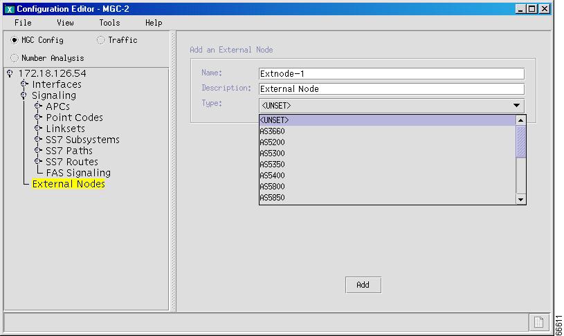
Adding External Nodes
An external node is a node with which the MGC communicates, either directly or indirectly. Here the media gateway is the external node. Table 4-10 lists the external node properties. Use the values in the table as you add external nodes to your MGC.
Use the external node component to add MGWs. You must create an external node for each MGW.
Note
Use the following procedure to add an external node to the MGC. Where necessary, refer to Table 4-10 for property values.
Step 1
Figure 4-21 Adding External Nodes
Step 2
Step 3
Step 4
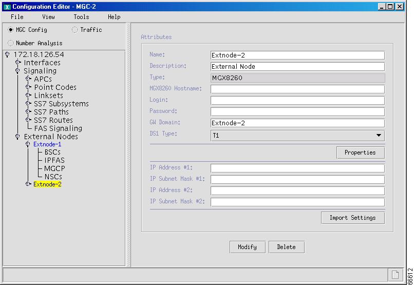
Configuring MGWs
An MGW is the interface between the QoS packet network and the PSTN/ISDN network. A gateway digitizes and compresses voice calls from the PSTN, creating IP packets for routing to another gateway (for forwarding to the PSTN) or to a terminal.
Note
Table 4-11 lists the MGW properties. Use the values in the table as you configure MGWs.
Use the following procedure to configure the external node as an MGW. Where necessary, refer to Table 4-11 for property values.
Step 1
Figure 4-22 Configuring an MGW
Step 2
Step 3
Step 4
Step 5
Step 6
Note
Step 7
Figure 4-23 Properties
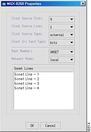
Step 8
Step 9
Step 10
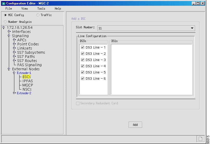
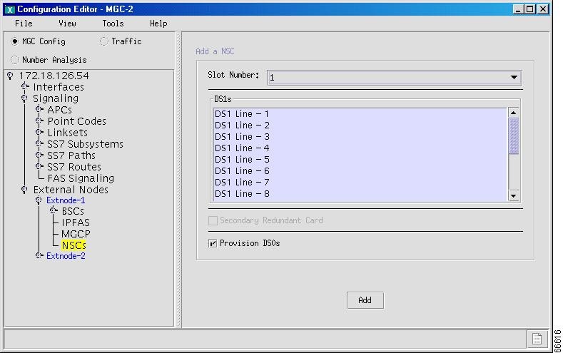
Adding a Broadband or Narrowband Service Card
A broadband switching card (BSC) provides high density TDM switching capability to the MGX8260. If a BSC is installed in the external gateway, provision it beginning with Step 1, below. If a narrowband service card (NSC) is installed, start with Step 5.
Step 1
Figure 4-24 Configured BSCs
Step 2
Step 3
Step 4
Step 5
Figure 4-25 Add an NSC
Step 6
Step 7
Step 8
Step 9
Step 10
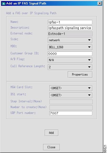
Adding an IPFAS Signaling Service
An Internet Protocol Facility Associated Signaling (IPFAS) signaling service defines the FAS or NFAS over IP transport service or signaling path from a MGC node to a media gateway. Table 4-12 lists the IPFAS signaling service properties.
Use the following procedure to add the ipfaspaths from the media gateway. The MML component name is IPFASPath. In the following example, it is the PRI backhaul path from the media gateway. Where necessary, refer to Table 4-12 for property values.
Step 1
Figure 4-26 Adding an IPFAS Signaling Service
Step 2
Step 3
Step 4
•
•
Step 5
Step 6
Step 7
Step 8
Step 9
Step 10
Step 11
Step 12
Note
Step 13
Note
Figure 4-27 IPFAS Signaling Service Added
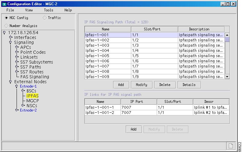
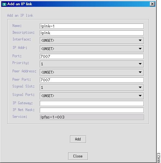
Adding IP Links for IPFAS
AN IP link for IPFAS identifies the IP link connection to support the IPFAS service between an MGC node Ethernet interface and an MGW. Table 4-13 lists the IP link properties. Use the values in the table as you add IP links to the MGC.
Use the following procedure to add IPFASPath IP links. Where necessary, refer to Table 4-13 for property values.
Step 1
Figure 4-28 Add an IP Link
Step 2
Step 3
Step 4
Step 5
•
•
•
•
Note
Step 6
Step 7
Step 8
Step 9
Step 10

Caution
Step 11
Step 12
Step 13
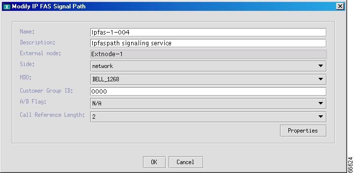
Changing IPFAS Signaling Service Properties
You can modify the properties of the IPFAS signaling services you have created. These properties apply to all IPFAS signaling services you create. You do not have to change the default properties. For a list of signaling service properties, default values, and descriptions, see the Cisco Media Gateway Controller Software Release 7 Provisioning Guide.
Use the following procedure to add or change IPFAS signaling service properties:
Step 1
Figure 4-29 Adding and Changing IPFAS Signaling Properties
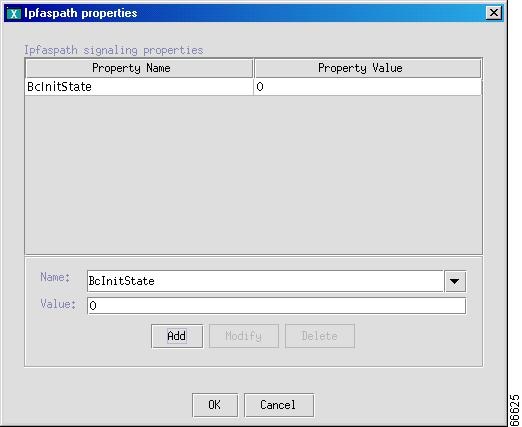
Step 2
Step 3
Figure 4-30 IPFAS Signaling Service Property Added
Step 4
Step 5
Step 6
Step 7
Step 8
Step 9
Step 10
Note
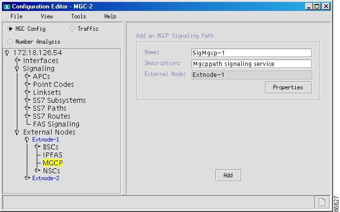
Adding an MGCP Signaling Service
The MGCP signaling service specifies the path that the MGC node uses to communicate with an MGW. The MML component name is MGCPPATH. Table 4-14 lists the MGC signaling service properties. Use the values in the table as you add an MGCP signaling service.
Note
Use the following procedure to add MGCP signaling service paths to the MGW. Where necessary, refer to Table 4-14 for property values.
Step 1
Figure 4-31 Adding MGCP Signaling Service
Step 2
Step 3
Step 4
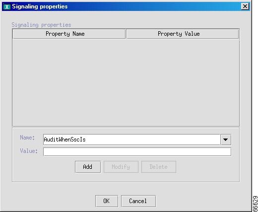
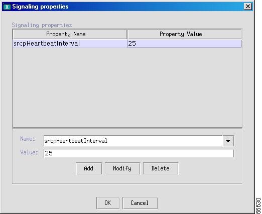
Adding and Changing MGCP Signaling Service Properties
Add or change the properties of the signaling service you have created. Your additions or changes are applied to all signaling services you create. You do not have to change the default properties. For a list of signaling service properties, default values, and descriptions, see the Cisco Media Gateway Controller Software Release 7 Provisioning Guide.
You must set the following properties for all MGCP signaling services defined in your Cisco Media Gateway Controller:
•
The media gateway MGCP domain name is a property of the MGW object. You can derive the MGCP domain name from the MGCP path object because each MGCP path object refers to an external node and each external node refers to an MGW.
•
Use the following procedure to add or change MGCP signaling service properties:
Step 1
Figure 4-32 Adding and Changing MGCP Signaling Properties
Step 2
Figure 4-33 MGCP Signaling Service Property Added
Step 3
Step 4
Step 5
Step 6
Note
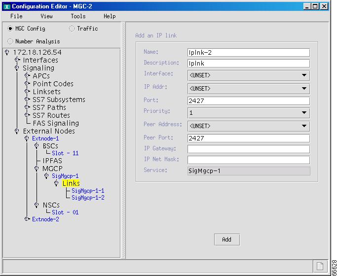
Add an IP Link for MGCP
An IP link for MGCP identifies the connection that supports the MGCP service between an MGC Ethernet interface and a media gateway. Use the following procedure to add an MGCP IP link:
Step 1
Figure 4-34 Adding MGCP IP Links
Step 2
Step 3
Step 4
Step 5
•
•
•
•
Note
Step 6
Step 7
Step 8
Step 9
Step 10
Step 11
Configuring Bearer Traffic
Bearer traffic includes information on the trunk groups, trunks, and trunk routing required by an MGC to direct calls. It uses this information in conjunction with a dial plan to perform number analysis and route selection.
A trunk is a speech path between any two switches. Trunks are DS0 endpoints; one trunk can ride on one DS0, or one DS0 can carry one trunk. A trunk group is a collection of DS0 circuits arranged so that dialing a single trunk number provides access to the entire trunk group, and a trunk route is a set of trunk groups.
The configuration example in this section uses SS7 and PRI trunks.
The two main scenarios you are likely to follow when setting up the MGC node for call routing are described in Table 4-15.
Table 4-15 Setting Up the MGC Node for Call Routing
Create a new configuration
•
•
•
•
Modify an existing configuration
•
–
–
•
•
•
•
Caution
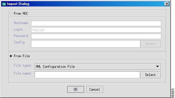
Importing Trunk Groups and Trunks
You can import the trunk groups and trunks to make them available to the MGC. Consider importing a trunk group for initial provisioning only. When you import a trunk group, all of the existing trunk groups are replaced by the imported trunk groups, and all existing trunks are deleted.
Note
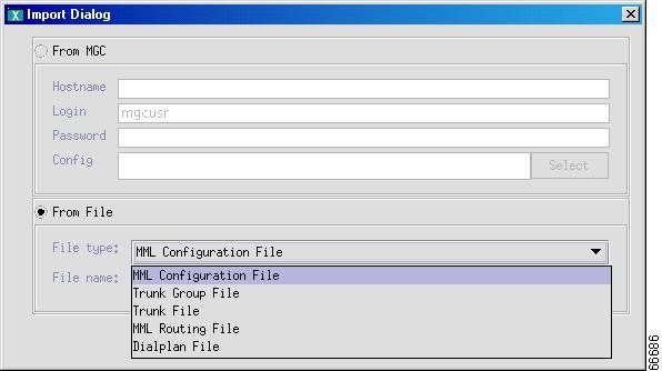
Perform the following steps to import a trunk group or trunk:
Step 1
Figure 4-35 Importing Files
Step 2
Figure 4-36 Imported File Type
Step 3
Figure 4-37 Selecting the File to Import
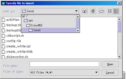
Step 4
Step 5
Add a Trunk Group
Tip
Use the following procedure to add a trunk group:
Step 1
Step 2
Figure 4-38 Defining a Trunk Group
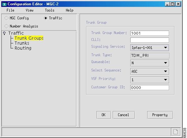
Note
Step 3
Step 4
Step 5
Step 6
Step 7
Step 8
Step 9
Step 10
Step 11
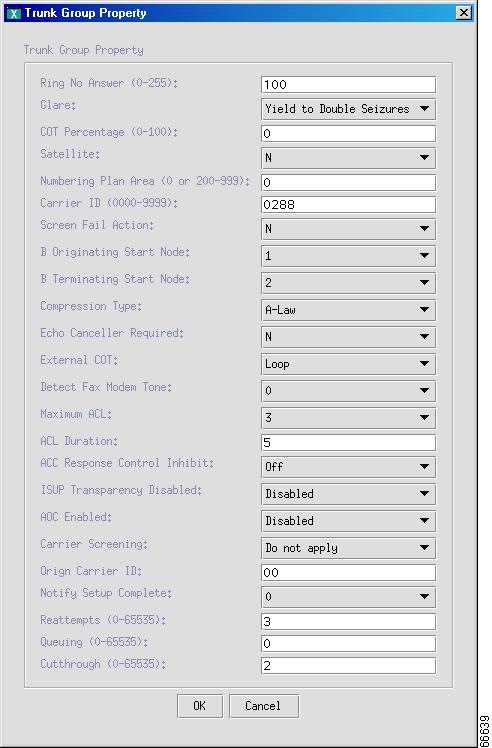
Figure 4-39 Trunk Group Properties
.
Step 12
Step 13
Step 14
Figure 4-40 Trunk Group Added
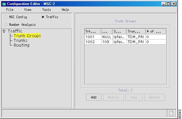
Note
Adding Trunks
Use the following procedure to add trunks to a trunk group:
Step 1
Figure 4-41 Adding a Trunk
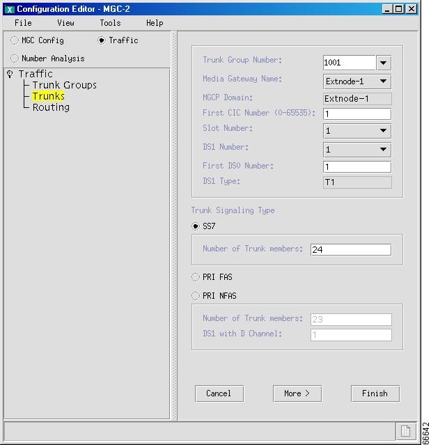
Step 2
Step 3
Step 4
Step 5
Step 6
Step 7
Step 8
Step 9
Step 10
•
•
Note
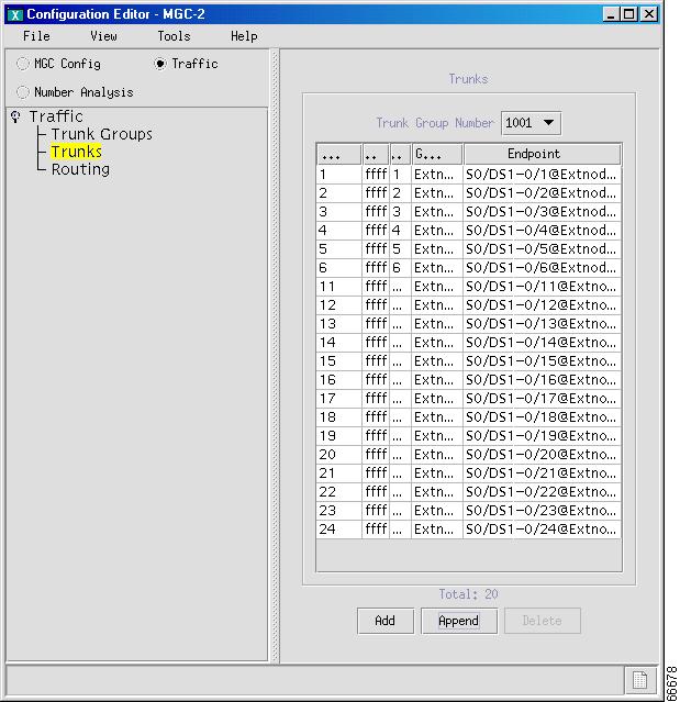
Step 11
Step 12
Step 13
Figure 4-42 Trunks Added

Deleting Trunks from a Trunk Group
Use the following procedure to delete individual trunks from a trunk group:
Step 1
Step 2
•
•
•
Step 3
Figure 4-43 Trunks Deleted
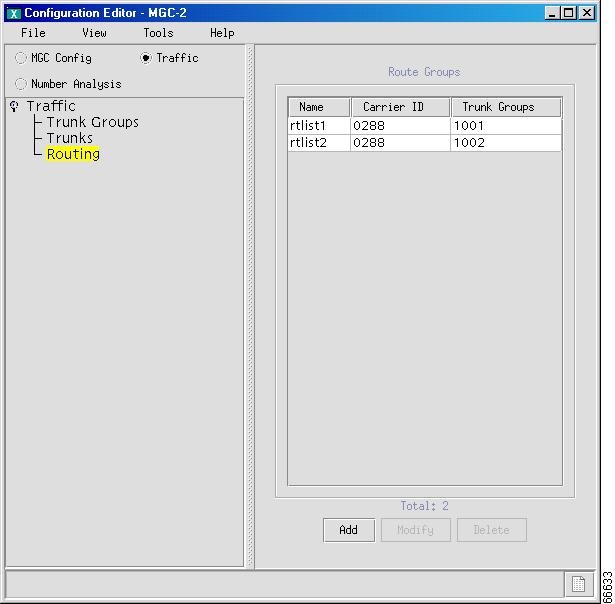
Adding Route Groups and Routes
A route group is a collection of routes going to the same endpoint. Define the route groups, and then associate a trunk group with each route group. Use the following procedure to add a route group:
Step 1
Figure 4-44 Adding a Route

Step 2
Step 3
Step 4
Tip
Step 5
Figure 4-45 Route Group Added
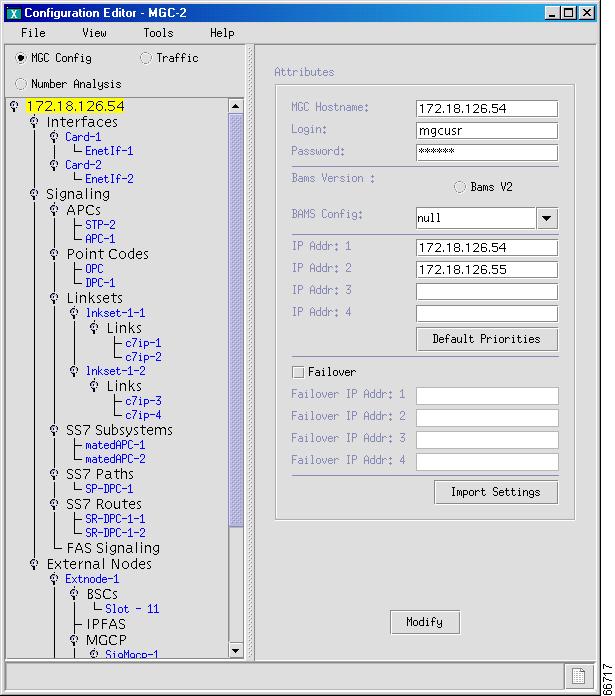
Hierarchical View of Provisioned Components
The results of the provisioning session you completed are visible in the hierarchical tree in the left pane of the main VSPT screen. You can expand the branches to view individual component (see Figure 4-46).
Figure 4-46 Hierarchical Tree of Components
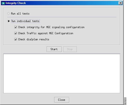
Performing an Integrity Check
When provisioning is complete, you can perform an integrity check to prevent possible configuration errors. The integrity check verifies:
•
•
•
Each integrity check is explained in more detail in the following subsections.
Checking Integrity for MGC Signaling Configuration
When you perform an integrity check for an MGC signaling configuration, the Voice Services Provisioning Tool does the following:
•
•
•
•
•
•
•
•
•
–
–
–
–
Note
Checking Traffic Against MGC Configuration
When you perform an integrity check of traffic against the MGC configuration, the Voice Services Provisioning Tool does the following:
•
•
•
For information about an integrity check of dial plan results, refer to the Cisco Media Gateway Controller Software Release 7 Dial Plan Guide.
Use the following procedure to perform an integrity check of your configuration:
Step 1
Figure 4-47 Integrity Check
Step 2
When the tests finish, a screen similar to the one in Figure 4-48 appears and displays the results of the integrity checks performed.
Figure 4-48 Integrity Check Results

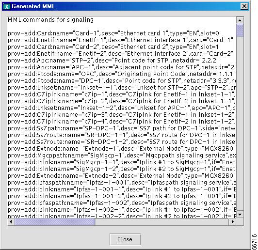
Viewing Generated MML
The VSPT application automatically generates the MML commands to provision your Cisco MGC and saves these commands in a file to be executed when you deploy the configuration. If you want to view the MML commands generated from your VSPT provisioning session, click View > MML. Screens displaying generated MML commands, similar to the one shown in Figure 4-49, appear.
Figure 4-49 First Generated MML Screen
Viewing Generated Cisco MGW Commands
To view the Cisco MGW commands generated from your provisioning session, click View > MGW Commands. A screen with generated Cisco MGW commands, similar to that shown in Figure 4-50, appears.
Figure 4-50 Generated Cisco MGW Commands

Deploying a New Configuration
When you finish defining a configuration, you must deploy that configuration to the Cisco MGC. A new configuration should not be deployed during times of peak load on the Cisco MGC.
The new configuration can be deployed completely or in parts, known as an incremental deployment. Deploying incrementally allows you to verify each component type configuration before proceeding to the next component deployment.
The Cisco MGC does not support some incremental deployment processes. If you have problems with an incremental deployment, you should visually inspect the commands to ensure that you have properly configured the desired components. Modify those presenting the problem, or cancel the deployment and redeploy as a new configuration.
If you want to delete a component and plan to reuse the component name, delete the component, deploy the session, and verify that the component has been deleted before reusing the name.
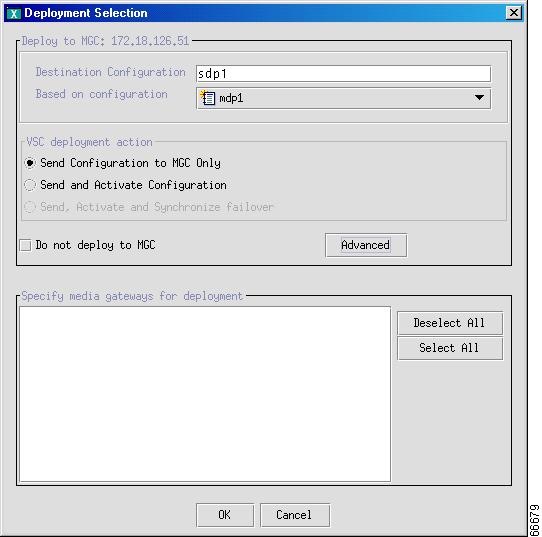
Use the following procedure to deploy a new configuration:
Step 1
Figure 4-51 Deploying a Configuration
Step 2
Step 3
Step 4
Figure 4-52 Incremental Deployment Component Selector
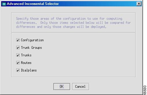
Step 5
Step 6
•
•
•
•
Step 7
Step 8
Figure 4-53 Deployment Progress
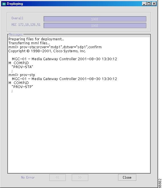
Note
Backup and Restore
The VSPT backup and restore tool enables a user to create, modify, and delete scheduled backups and restores hourly, daily, weekly, or monthly or on demand. Backup and restore activities can be performed on any of the following devices that have been configured for the MGC:
•
•
•
•
•
•
The backup and restore tool also provides the status of each activity and generates user-viewable status logs.
Note
Schedule An Activity
Use the following procedure to open the VSPT backup and restore tool and schedule an activity:
Step 1
Figure 4-54 Backup and Restore Utility
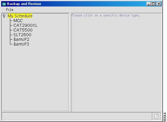
Step 2
Figure 4-55 Scheduling a Backup or Restore
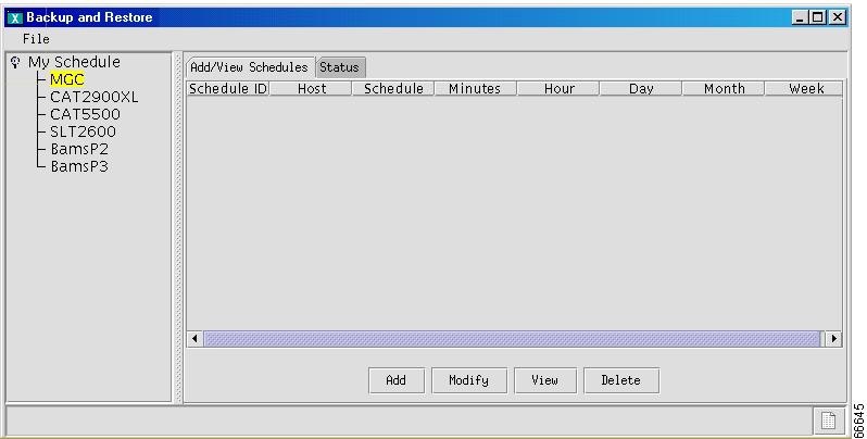
Note
Step 3
Figure 4-56 Schedule an Activity
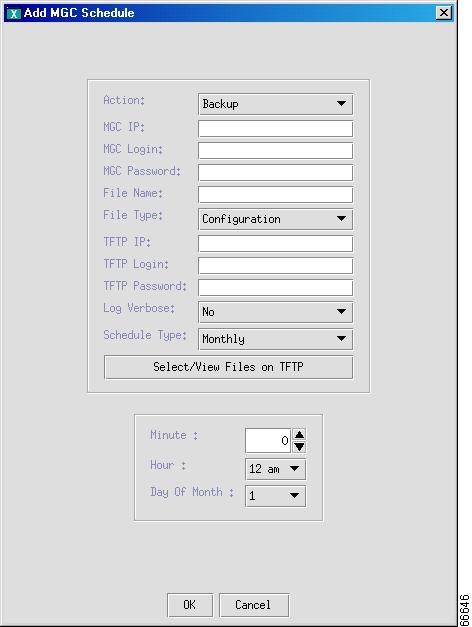
Note
Step 4
Step 5
Step 6
Step 7
Step 8
Step 9
Step 10
Step 11
•
•
•
•
•
•
Step 12
Step 13
Figure 4-57 Display Activity Schedule
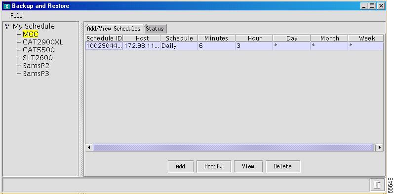
After the backup has been completed, the status of the activity is available immediately. The backup file with the name you specified is available for use with the VSPT to perform a restore.
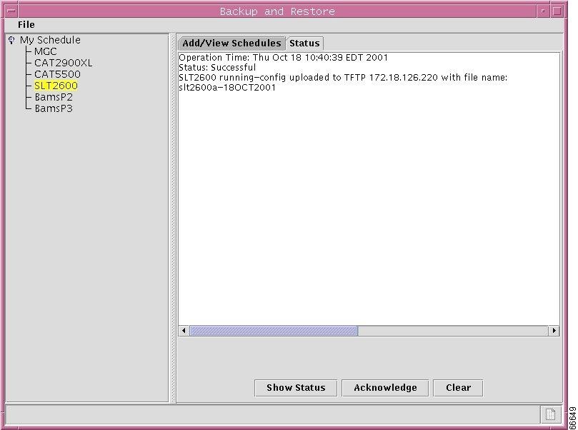
Check Status of Backup or Restore
The VSPT generates status logs that provide information about each scheduled backup or restore activity. The status log displays the following information for the activity:
•
•
•
•
•
If you have specified verbose log mode, the status log also displays the sequence of commands issued by the VSPT and any system responses.
Use the following procedure to check the status of a backup or restore activity:
Step 1
Figure 4-58 Backup and Restore Status Tab
.
Step 2
•
•
•
Provisioning the Billing and Measurements Server
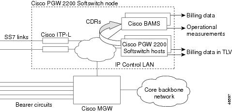
The Cisco Billing and Measurements Server (BAMS) provides enhanced billing and measurement functions corresponding to those found in a traditional Class 4 tandem switch. The BAMS server collects, formats, and stores billing and measurement data from the Cisco MGC. The data can then be processed by a billing system and other measurement collection and reporting systems. BAMS runs on a standalone server designed to interface with the Cisco MGC.
.Figure 4-59 provides an overview of the BAMS components.
Figure 4-59 BAMS Overview
The VSPT helps you create, copy, modify, and deploy a configuration for the BAM server. The BAMS provisioning session can exist as a standalone provisioning application using MML commands.
The VSPT performs the following tasks when you are configuring BAMS:
•
•
•
•
•
•
•
The steps necessary to provision a BAMS are:
•
–
–
–
•
–
–
–
–
•
–
–
•
Note
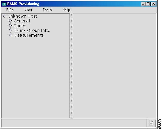
Starting a BAMS Provisioning Session
Use the following procedure to provision a BAMS:
Step 1
Step 2
Step 3
Figure 4-60 BAMS Configuration Screen
Step 4
Step 5
Figure 4-61 New Configuration Wizard
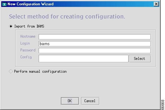
Step 6
If you want to manually configure the BAMS, select the Perform manual configuration radio button, and click OK. A screen similar to the one shown in Figure 4-62 appears.
Figure 4-62 BAMS Configuration
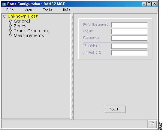
Step 7
Step 8
Step 9
Step 10
BAMS Provisioning
This section provides directions for using the VSPT to provision a BAMS server. The VSPT performs the following procedures:
•
•
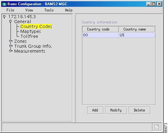
Provisioning General Information
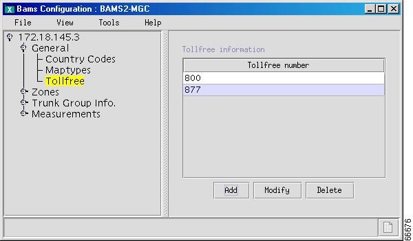
Provisioning general BAMS information includes defining country codes, map types, and tollfree prefixes. Use the following procedure to configure general BAMS information:
Step 1
Step 2
Step 3
Figure 4-63 Country Code Added
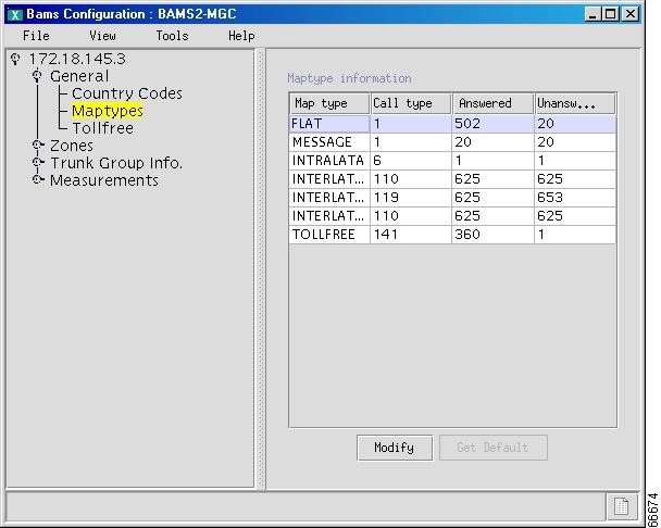
Step 4
Figure 4-64 Maptype Information Added
Step 5
Step 6
Figure 4-65 Tollfree Information Added
Step 7
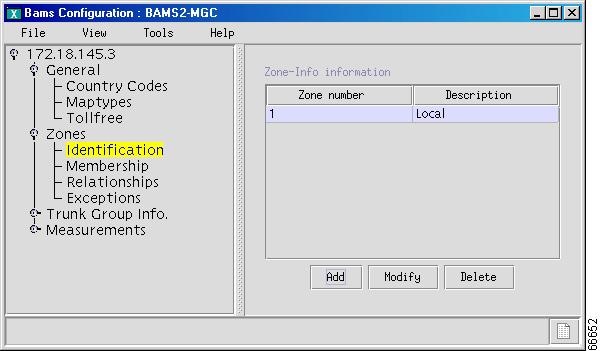
Provisioning Zones
Note
Zoning provides a mechanism for differentiating between rating types. Each supported NPANXX combination must be a member of a zone.
Use the following procedure to provision zones:
Step 1
Step 2
Step 3
Figure 4-66 Zone Information Added
Step 4
Figure 4-67 Add Npanxx
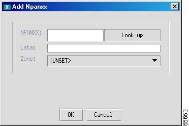
Step 5
Step 6
Step 7
Step 8
Step 9
Figure 4-68 Membership Information Added

Step 10
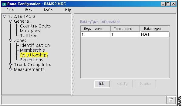
Figure 4-69 Add Rating Type
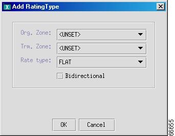
Step 11
Step 12
Figure 4-70 Rating Type Information Added
Step 13
Figure 4-71 Add Rate Exception
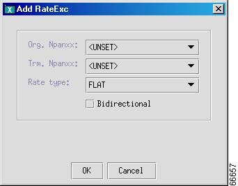
Step 14
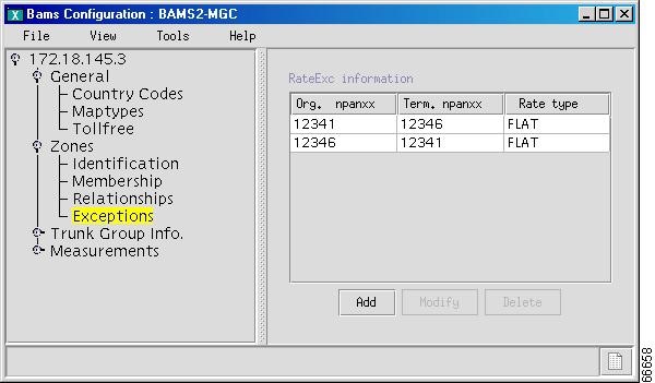
Step 15
Figure 4-72 Exception Added
Provisioning Trunk Group Information
Provisioning trunk group information includes:
•
•
•
Use the following procedure to provision trunk group information:
Step 1
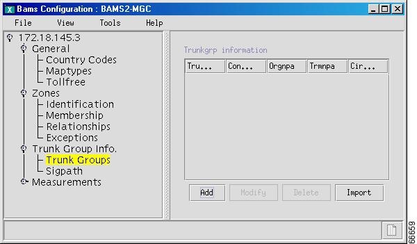
Step 2
Figure 4-73 Configure BAMS Trunk Groups
Step 3
Step 4
Step 5
Figure 4-74 Add Trunkgrp
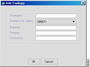
Step 6
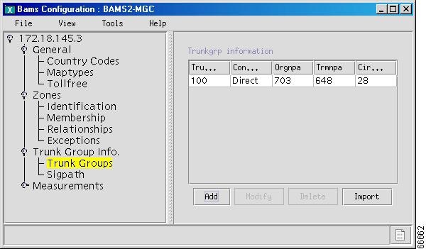
Step 7
Figure 4-75 Trunk Group Added
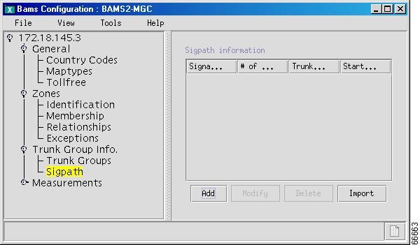
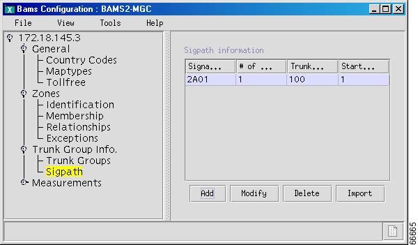
Step 8
Figure 4-76 Configure a BAMS Sigpath
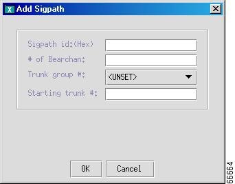
Step 9
Step 10
Figure 4-77 Add Sigpath
Step 11
Figure 4-78 Sigpath Added
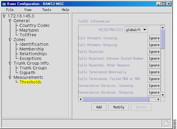
Provisioning Measurements
BAMS generates and maintains measurements, which are performance indicators that constitute a history of traffic statistics on a network. Each measurement value represents an accumulation of activity that took place during a specific interval.
Use the following procedure to configure measurement types and properties:
Step 1
Figure 4-79 Configuring BAMS Thresholds
Step 2
Step 3
Figure 4-80 Add TcaTbl
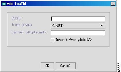
Step 4
Step 5
Step 6
After the BAMS server is provisioned, you must deploy the new configuration. Refer to the "Deploying a New Configuration" section for instructions.
 Feedback