Global Deployments
Global deployments allows service providers to deploy remote sites with centralized management. The following global deployment topologies are supported with standard HCS for CC for CC deployment models.
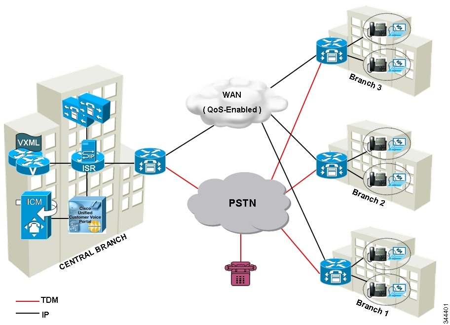
Remote CVP Deployment
The Remote CVP deployment requires the following servers deployed at the remote sites. The maximum RTT with central controller over the WAN is restricted up to 400 ms.
Prerequisite: Standard HCS for CC for CC deployment model at the Data center.
Unified CVP Servers for Remote CVP Deployment
Use the Golden Template tool to deploy the remote CVP servers from the Golden templates. This section explains the procedures to configure Unified CVP servers at Remote Site.
Configure Remote CVP Server
To configure the remote CVP servers, See Configure Unified CVP Server
Configure Operations Console for Remote CVP for Remote Deployment
Configure Unified CVP Call Server for Remote Deployment
Procedure
| Step 1 |
On the Unified CVP OAMP server, go to . |
| Step 2 |
Click Operations Console and log in. |
| Step 3 |
Navigate to Device Management > Unified CVP Call Server. |
| Step 4 |
Click Add New. |
| Step 5 |
On the General tab, enter the IP address and the hostname of the Cisco Unified CVP Server. Check ICM, IVR, and SIP. Click Next. |
| Step 6 |
Click the ICM tab. For each of the Cisco Unified CVP Call Servers, retain the default port of 5000 for the VRU Connection Port. |
| Step 7 |
Click the SIP tab:
|
| Step 8 |
Click the Device Pool tab. Make sure the default device pool is selected. |
| Step 9 |
(Optional) Click the Infrastructure tab. In the Configuration Syslog Settings pane, configure these fields as follows: |
| Step 10 |
Click Save & Deploy. |
| Step 11 |
Repeat this procedure for the remaining Unified CVP Call Servers. |
Configure SIP Server Group for Remote Deployment
SIP Server Groups are required for Cisco Unified Communications Manager and Gateways.
Procedure
| Step 1 |
In the Unified CVP Operations Console, navigate to . |
||
| Step 2 |
Create a server group for the Cisco Unified Communications Manager devices: |
||
| Step 3 |
Create a server group for the gateway devices: |
||
| Step 4 |
Associate these server groups to all Unified CVP Call Servers:
|
||
| Step 5 |
Click Heartbeat Properties and make the following changes, else skip this step.
|
||
| Step 6 |
Click Deployment Status to make sure that you applied the configuration.
|
Unified CCE Servers for Remote CVP Deployment
Use the Golden Template tool to deploy the remote CCE VRU PG from the Golden templates. This section explains the procedures to configure Unified CCE at Remote Site.
Modify Unified CCE Router
See Configure the Unified CCE Router and modify the value in Enable Peripheral Gateways dialog box by incrementing the value.
Add Remote VRU PG Using Unified CCE Configuration Manager
Complete the following procedure to add remote VRU PG using Unified CCE Configuration Manager.
Procedure
| Step 1 |
On the Unified CCE Admin Workstation Server, navigate to Start > Cisco Unified CCE Tools > Administration Tools > Configuration Manager. |
| Step 2 |
In Configuration Manager Window, expand Tools > Explorer Tools and open PG Explorer. Add the Remote VRU PG, PIMs and Routing clients. |
| Step 3 |
Navigate Tools > Explorer Tools and open Network VRU Explorer. Associate the Network VRU label with the remote VRU PG Routing clients. |
| Step 4 |
Navigate Tools > List Tools and open Expanded Call Variable List. Enable the ECC variable user.microapp.media_server. |
| Step 5 |
Navigate Tools > List Tools and open Agent Targeting Rule. Add the remote VRU PG routing clients. |
Configure VRU PG for Remote CVP Deployment
Complete the following tasks to configure the Unified CCE peripheral gateways for the PG Server on Side A and then repeat the same procedure for Side B.
Procedure
| Step 1 |
Choose Start > All programs > Cisco Unified CCE Tools >Peripheral Gateway Setup. |
||
| Step 2 |
Click Add in the ICM Instances pane.
|
||
| Step 3 |
Click Add in the Instance Components pane, and from the Component Selection dialog box choose Peripheral Gateway. |
||
| Step 4 |
In the Peripheral Gateway Properties dialog box:
|
||
| Step 5 |
In the Peripheral Interface Manager pane of the Peripheral Gateway Component Properties dialog box, click Add and configure PIM1 with the Client Type of VRU as follows:
|
||
| Step 6 |
Refer to PG Explorer and Enter the value in the Logical Controller ID field. |
||
| Step 7 |
Enter 0 in the CTI Call Wrapup Data delay field. |
||
| Step 8 |
In the VRU Reporting pane, select Service Control and check Queue Reporting, Click Next. |
||
| Step 9 |
In the Device Management Protocol Properties dialog box, configure as follows:
|
||
| Step 10 |
In the Peripheral Gateway Network Interfaces dialog box, enter the PG Private Interfaces and the PG Public (Visible) Interfaces.
|
||
| Step 11 |
In the Check Setup Information dialog box, click Next. |
||
| Step 12 |
In the Setup Complete dialog box, click Finish.
|
Remote CVP and CUCM Deployment
The Remote CVP and CUCM deployment requires the following servers deployed at the remote sites. The maximum RTT with central controller over the WAN is restricted up to 400 ms. Use the Golden Template tool to deploy the remote CCE, CVP, CUCM, and Finesse servers from the Golden templates.
Prerequisite: Standard HCS for CC for CC deployment model at the Data Center:
Unified CCE Servers for Remote CVP and CUCM Deployment
Use the Golden Template tool to deploy the remote CCE Agent PG from the Golden templates. This section explains the procedures to configure Unified CCE servers at Remote Site.
Modify Unified CCE Router
See Configure the Unified CCE Router and modify the value in Enable Peripheral Gateways dialog box by incrementing the value.
Add Remote Agent PG Using Unified CCE Configuration Manager
Complete the following procedure to add remote Agent PG using Unified CCE Configuration Manager.
Procedure
| Step 1 |
On the Unified CCE Admin Workstation Server, navigate to Start > Cisco Unified CCE Tools > Administration Tools > Configuration Manager. |
| Step 2 |
In Configuration Manager Window, expand Tools > Explorer Tools and open PG Explorer. Add the Remote Agent PG, CUCM and VRU PIMs and their Routing clients. |
| Step 3 |
Navigate Tools > Explorer Tools and open Network VRU Explorer. Associate the Network VRU label with the remote Agent PG Routing clients. |
| Step 4 |
Navigate Tools > List Tools and open Expanded Call Variable List. Enable the ECC variable user.microapp.media_server. |
| Step 5 |
Navigate Tools > List Tools and open Agent Targeting Rule. Add the remote Agent PG routing clients. |
Configure Agent PG for Remote CVP and CUCM Deployment
Complete the following tasks to configure the Unified CCE peripheral gateways for the PG Server on Side A and then repeat the same procedure for Side B.
Procedure
| Step 1 |
Choose Start > All programs > Cisco Unified CCE Tools >Peripheral Gateway Setup. |
||
| Step 2 |
Click Add in the ICM Instances pane.
|
||
| Step 3 |
Click Add in the Instance Components pane, and from the Component Selection dialog box choose Peripheral Gateway. |
||
| Step 4 |
In the Peripheral Gateway Properties dialog box:
|
||
| Step 5 |
In the Peripheral Interface Manager pane of the Peripheral Gateway Component Properties dialog box, click Add and configure PIM1 with the Client Type of CUCM as follows: |
||
| Step 6 |
In the Peripheral Interface Manager pane of the Peripheral Gateway Component Properties dialog box, click Add and configure PIM2 with the Client Type of VRU as follows:
|
||
| Step 7 |
Refer to PG Explorer and Enter the value in the Logical Controller ID field. |
||
| Step 8 |
Enter 0 in the CTI Call Wrapup Data delay field. |
||
| Step 9 |
In the VRU Reporting pane, select Service Control and check Queue Reporting. Click Next. |
||
| Step 10 |
In the Device Management Protocol Properties dialog box, configure as follows:
|
||
| Step 11 |
In the Peripheral Gateway Network Interfaces dialog box, enter the PG Private Interfaces and the PG Public (Visible) Interfaces.
|
||
| Step 12 |
In the Check Setup Information dialog box, click Next. |
||
| Step 13 |
In the Setup Complete dialog box, click Finish.
|
 Feedback