Clone and OS Customization Process

The documentation set for this product strives to use bias-free language. For the purposes of this documentation set, bias-free is defined as language that does not imply discrimination based on age, disability, gender, racial identity, ethnic identity, sexual orientation, socioeconomic status, and intersectionality. Exceptions may be present in the documentation due to language that is hardcoded in the user interfaces of the product software, language used based on RFP documentation, or language that is used by a referenced third-party product. Learn more about how Cisco is using Inclusive Language.
For the following automation software and download information see, Automation Software section in Cisco HCS for Contact Center Installing and Upgrading Guide http://www.cisco.com/c/en/us/support/unified-communications/hosted-collaboration-solution-contact-center/products-installation-guides-list.html
GoldenTemplateTool
PowerCLI
OVF Tool
WinImage
| Sequence | Task | Done |
|---|---|---|
| 1 | Download Golden Template Automation Tool | |
| 2 | Complete Automation Spreadsheet | |
| 3 | Run Automation Script | |
| 4 | OS Customization Process |
Golden Template Tool is required for automated cloning of Golden Templates and deploying the customized Virtual machines in a customer instance. To download and extract the Golden Template Tool, see Automated Cloning and OS Customization to the root of the C: drive on your system. You can browse the automation scripts using VMware vSphere PowerCLI.
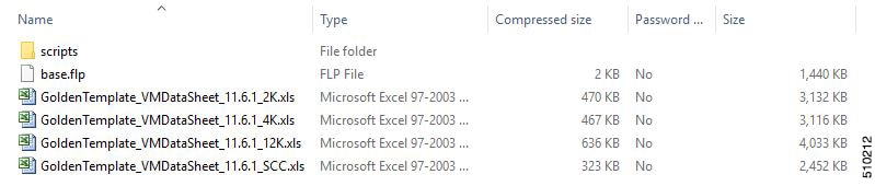
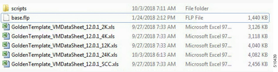
The extracted content includes the following:
The automation spreadsheets, which is the interface to the scripts.
The scripts folder that contains five scripts. The deployVM.PS1 file is the primary automation script, which calls the other four scripts.
The Archive, Log, OVF, PlatformConfigRepository, and Report folders are empty until you run the automation script for export.
After you run the script for the first time:
Archive holds the prior versions of the automation spreadsheet, saved with a date and a time stamp.
Log holds all the log files saved with a date and a time stamp.
OVF, when the tool runs the Export operation, a sub folder is created for each virtual machine. The folders take their names from the GOLDEN_TEMPLATE_NAME cells in the spreadsheet. These folders are used to import the virtual machines to the customer ESXi host.
PlatformConfigRepository is populated with three subfolders that holds XML files generated as part of the golden template process.
Report holds all automation reports, saved with a date and a time stamp.
Fill the information provided in the table to complete the automation spreadsheet for cloning process. Deploy VM automation script requires this information to clone the virtual machines to the customer instance.
The table describes the values of each virtual server and associated properties:
| Column | Domain-based VM | Workgroup-based VM | VOS-based VM |
|---|---|---|---|
| CREATEVM | YES | YES | YES |
| CUSTOMIZATION | YES | YES | YES |
| OPERATION | |||
| SOURCE_HOST_IP | 10.10.0.10 | 10.10.0.10 | 10.10.0.10 |
| SOURCE_DATASTORE_NAME | Datastore-A0 | Datastore-A0 | Datastore-A0 |
| SOURCE_VMNAME | |||
|
OVF_NETWORK1 |
|||
|
OVF_NETWORK2 |
|||
| GOLDEN_TEMPLATE_NAME | GT-Rogger | GT-CVP-Server | GT-CUCM |
| NEW_VM_NAME | CCE-RGR-SIDE-A | CVP-SVR-SIDE-A | UCM-SUB-SIDE-A |
| DEST_HOST_IP | 10.10.1.10 | 10.10.1.11 | 10.10.1.12 |
| DEST_DATASTORE_NAME | Datastore-A1 | Datastore-A3 | Datastore-A6 |
| PRODUCT_VERSION | 10.0.1 | ||
| COMPUTER_NAME | CCE-RGR-SIDE-A | CVP-SVR-SIDE-A | UCM-SUB-SIDE-A |
| WORK_GROUP | NO | YES | |
| WORK_GROUP_NAME | WORKGROUP | ||
| DOMAIN_NAME | HCSCC.COM |
HCSCC.COM
(Optional) |
|
| TIME_ZONE_LINUX_AREA | America | ||
| TIMEZONE_LINUX_LOCATION | Los Angeles | ||
| TIME_ZONE_WINDOWS | (GMT-08:00) | (GMT-08:00) | |
| DOMAIN_USER | HCSCC\administrator | ||
| DOMAIN_PASSWORD | •••••••• | ||
| PRODUCT_KEY | XXXX-XXXX-XXXX-XXXX | XXXX-XXXX-XXXX-XXXX | |
| OWNER_NAME | HCS | HCS | |
| ORGANIZATION_NAME | CISCO | CISCO | CISCO |
| ORGANIZATION_UNIT | HCS | ||
| ORGANIZATION_LOCATION | San Jose | ||
| ORGANIZATION_STATE | CA | ||
| ORGANIZATION_COUNTRY | USA | ||
| NTP_SERVER | 10.81.254.131 | ||
| NIC_NUM | 2 | 1 | 1 |
| IP_ADDRESS_NIC1 | 10.10.10.10 | 10.10.10.20 | 10.10.10.30 |
| SUB_NET_MASK_NIC1 | 255.255.255.0 | 255.255.255.0 | 255.255.255.0 |
| DEFAULT_GATEWAY_NIC1 | 10.10.10.1 | 10.10.10.1 | 10.10.10.1 |
| DNS_IP_NIC1 | 10.10.10.3 | 10.10.10.3 | 10.10.10.3 |
| DNS_ALTERNATE_NIC1 | |||
| IP_ADDRESS_NIC2 | 192.168.10.10 | ||
| SUB_NET_MASK_NIC2 | 255.255.255.0 | ||
| DEFAULT_GATEWAY_NIC2 | 192.168.10.1 | ||
| DNS_IP_NIC2 | 192.168.10.3 | ||
| DNS_ALTERNATE_NIC2 | |||
|
VM_NETWORK |
Download and install VMware vSphere PowerCLI on the client computer.
For more information, see Automated Cloning and OS Customization
 Note |
Ensure WinImage (32-bit) is installed in the following location: C:\Program Files (x86)\WinImage |
Note |
If you import any of the VOS VMs and have an unlicensed copy of WinImage, displays the popup for each VOS platform. Click OK to continue the import process. |
| Step 1 |
Sign-in as an administrator and open VMware vSphere PowerCLI (32-bit) application. |
||||
| Step 2 |
Enter the get-executionPolicy command to determine the restricted execution policy. |
||||
| Step 3 |
If the policy
is restricted, enter
set-executionPolicy command. At the
Change the execution policy to run unsigned scripts on your local computer and signed scripts from other users. |
||||
| Step 4 |
Enter the CD < GoldenTemplate directory> command. |
||||
| Step 5 |
Run the automation script using the following syntax:
This starts the script that parses and validates the data, creates entries in the GoldenTemplate directory. Displays the completion percentage on the screen and generates the Status Report in the Report folder. Click the Log File link in the Status report to debug error conditions and to consult Cisco Support. 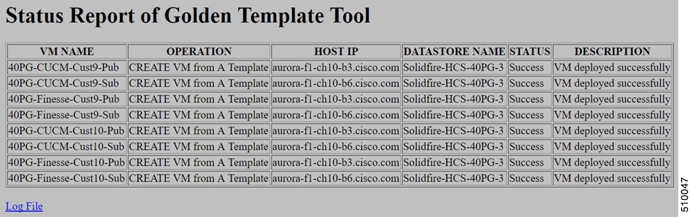 |
| Sequence | Task | Done |
|---|---|---|
| Windows Customization Process | ||
| 1 | ||
| 2 | ||
| VOS Customization Process | ||
| 1 | Configure DNS Server | |
| 2 | ||
| 3 | ||
Perform this procedure for all Windows VMs.
| Step 1 |
Select the Virtual Machine in the vSphere client. Right-click the VM and choose Edit settings. |
||
| Step 2 |
On the Hardware tab, select each Network adapter. Make sure that Connect at power on in the Device Status group is checked: |
||
| Step 3 |
Power on the virtual machine.
|
||
| Step 4 |
Wait for the VM to restart and to apply customization. This can take five to ten minutes. |
Validate Network Adapter Settings and Power On initializes the customization process. Although you are prompted to press Ctrl-Alt-Delete after powering on, doing do prevents the customization from taking effect. DO NOT press Ctrl-Alt-Del. If you inadvertently press Ctrl-Alt-Del, you have the following option to restore the customization.
| Step 1 |
Get the GoldenTemplate_VMDataSheet.xls from the C:/GoldenTemplateTool/Archive. |
| Step 2 |
Copy and paste the GoldenTemplate_VMDataSheet.xls to C:/GoldenTemplateTool. |
| Step 3 |
In the GoldenTemplate_VMDataSheet.xls select No in all the rows for the column CREATEVM except for those which needs to re-deploy. |
| Step 4 |
Else, you can enter that data manually for the VM. |
Perform this procedure for all Windows VMs.
| Step 1 |
Select . |
| Step 2 |
On the left panel, expand . |
| Step 3 |
On the right panel, right-click the administrator and select Set Password. |
| Step 4 |
Click Proceed at the warning message, then enter the new password. |
| Step 5 |
Click OK. |
| Step 6 |
Access the Registry Editor (). |
| Step 7 |
Select .
|
| Step 8 |
Restart the machine. If the machine is in the domain, log in to the domain. |
| Step 9 |
Enter NET TIME /DOMAIN:<domain> command to synchronize time with the domain controller. |
Before the Export process, ensure that the VM has only one Network Adapter to export.
When you complete the automation spreadsheet to export, fill only the columns so that the export automation script creates export OVFs in the OVF subfolder of the GoldenTemplate directory.
|
Column |
Description |
Example |
|---|---|---|
|
CREATEVM |
Select NO to skip VM creation. |
NO |
|
OPERATION |
Select ExportServer to specify the operation you are performing with the script. |
ExportServer |
|
SOURCE_HOST_IP |
The IP address of the physical server hosting the VM to be exported. |
xx.xx.xxx.xxx |
|
SOURCE_DATASTORE_NAME |
The name of the Datastore defined in VMware. |
datastore1(3) |
|
SOURCE_VMNAME |
The name of the VM that will be exported cannot contain spaces or special characters. Maximum of 32 characters. |
TemplateRoggerA |
|
GOLDEN_TEMPLATE_NAME |
New Name for the Exported VM cannot contain spaces or special characters. Maximum of 32 characters. |
CustomerRoggerA |
Leave all the other columns blank.
The export script processes the data in the export spreadsheet and validates that the required fields are present in the correct format.
The script creates a folder from which you can import the OVF at the desired location.
Note |
Run the script from the GoldenTemplate directory. |
Download and install VMware vSphere PowerCLI on the client computer.
For more information, see Automated Cloning and OS Customization
| Step 1 |
Launch VMware vSphere PowerCLI (32-Bit) as administrator. |
||||
| Step 2 |
Enter get-executionPolicy command to determine whether the Restricted Execution policy is in effect or is unrestricted. |
||||
| Step 3 |
If the policy is restricted, enter set-executionPolicy command. At the Supply Values prompt, enter Unrestricted and then enter Y. This changes the execution policy, so that you can run unsigned scripts that you write on your local computer and signed scripts from other users |
||||
| Step 4 |
Enter cd < GoldenTemplate directory> command. |
||||
| Step 5 |
Enter the command to run the automation script using the following syntax:
This starts a script that parses the data, validates the data, and creates entries in the OVF folder in the GoldenTemplate directory. Script gets executed despite of errors. Errors get displayed on the screen and stored in the log file. Script takes several hours to complete. After completion, script generates a status report in the Report folder. The status report has a link to the Log file. Use this file to debug error conditions and to consult with Cisco Support. |
After the successful completion of export process, the OVF files can be transferred to any desired location.
Note |
In that case, you would complete the import spreadsheet and run the import script from the USB drive. |
the ESXihost or vCenter
the datastores
To complete the automation spreadsheet for import, use the information provided in the table below. The import automation script requires this information to import the virtual machines to the desired ESXi host.
The table describes the values of each virtual server and associated properties.
|
Column |
Description |
Example |
|---|---|---|
|
CREATEVM |
Select YES to create a VM. Select NO to create a template. |
YES |
|
OPERATION |
Select ImportServer. |
ImportServer |
|
CUSTOMIZATION |
Select YES to apply values in the spreadsheet to the imported server. Select NO if you do not have the values at the time you complete the spreadsheet. If you do have the values but set to NO, the values will not be applied. |
YES |
|
SOURCE_HOST_IP |
Leave Blank |
Leave Blank |
|
SOURCE_DATASTORE_NAME |
Leave Blank |
Leave Blank |
|
SOURCE_VMNAME |
Leave blank. |
Leave blank. |
|
GOLDEN_TEMPLATE_NAME |
Enter the name of the exported golden template that is in OVF Subfolder. |
GTCS-1A |
|
NEW_VM_NAME |
The name for the new VM. Should not contain spaces or special characters. Maximum of 32 characters. |
CustomerRoggerA |
|
DEST_HOST_IP |
The IP address or the DNS name of the ESXi Host for the new VM. |
xx.xx.xxx.xxx |
|
DEST_DATASTORE_NAME |
The name of the Datastore for the new VM. |
datastore2(1) |
|
PRODUCT_VERSION |
Currently this field is applicable only for VOS Product |
11.x.x |
|
COMPUTER_NAME |
The NET BIOS name for the new computer. Maximum 15-characters. Do not use special characters. |
CUST-Rogger-A |
|
WORK_GROUP |
Dropdown: YES adds the VM to a WorkGroup and enables WORK_GROUP_NAME. NO adds the VM to a domain and enables DOMAIN_NAME, DOMAIN_USER, and DOMAIN_PASSWORD. |
NO |
|
WORK_GROUP_NAME |
Enter the Workgroup name. Used only if WORK_GROUP is set to YES. |
NA |
|
DOMAIN_NAME |
Enter the Domain name. Used only if WORK_GROUP is set to NO |
xx.xx.xxx.xxx |
|
TIME_ZONE_LINUX_AREA |
Drop-down selection of the timezone area to be set Unified CM. For the United States of America, select America. |
America |
|
TIME_ZONE_LINUX_LOCATION |
Drop-down selection of the timezone location to be set for Unified CM, CUIC, or Finesse. |
Eastern |
|
TIME_ZONE_WINDOWS |
Drop-down selection of the timezone to be set for the Unified CVP and Unified CCE VMs. |
(GMT-05:00) Eastern Time (US & Canada) |
|
DOMAIN_USER |
The user name for a domain user with privileges to add the new computer to the domain. Enabled only if WORK_GROUP is set to NO. |
DOMAIN\Username (Optional) |
|
DOMAIN_PASSWORD |
The password for the package123 domain user. Enabled only if WORK_GROUP is set to NO. |
package123 |
|
PRODUCT_KEY |
The valid Windows OS product key in the format xxxxx-xxxxx-xxxxx-xxxxx-xxxxx. |
ZZZM2-Y330L-HH123-99Y1B-GJ20B |
|
OWNER_NAME |
The full name of the owner. Administrator and Guest are not allowable names. This is a mandatory field for OS_TYPE Windows 2016. |
LabAdmin |
|
ORGANIZATION_NAME |
Set for Unified CM, CUIC, MediaSense or Finesse. |
MyName |
|
ORGANIZATION_UNIT |
Set for Unified CM, CUIC, MediaSense or Finesse. |
MyUnit |
|
ORGANIZATION_LOCATION |
Set for Unified CM, CUIC, MediaSense or Finesse. |
MyCity |
|
ORGANIZATION_STATE |
Set for Unified CM, CUIC, MediaSense or Finesse. |
MyState |
|
ORGANIZATION_COUNTRY |
Set the Organization Country drop-down list for Unified CM, CUIC, MediaSense or Finesse. |
United States of America |
|
NTP_SERVER |
The IP Address of the NTP server. |
xx.xx.xxx.xxx |
|
NIC_NUM |
Values in the field are pre-populated based on VM_TYPE field and are protected. Values are “1” or “2”. |
2 |
|
IP_ADDRESS_NIC1 |
A valid IPv4 address for NIC 1. Valid only if the value in the NIC_NUM fields is 1. |
xx.xx.xxx.xxx |
|
SUB_NET_MASK_NIC1 |
A valid subnet mask (IPv4 address) for NIC 1. |
xx.xx.xxx.xxx |
|
DEFAULT_GATEWAY_NIC1 |
A valid Default gateway (IPv4 address) for NIC1. |
xx.xx.xxx.xxx |
|
DNS_IP_NIC1 |
A valid IPv4 address for the primary DNS for NIC1. |
xx.xx.xxx.xxx |
|
IP_ADDRESS_NIC2 |
A valid IPv4 address for NIC 2. Valid only if the value in the NIC_NUM fields is 2. |
xx.xx.xxx.xxx |
|
SUB_NET_MASK_NIC2 |
A valid subnet mask (IPv4 address) for NIC 2. For Unified CCE VMs only. |
255.255.255.255 |
|
DNS_IP_NIC2 |
A valid IPv4 address for the primary DNS for NIC2. For Unified CCE VMs only. |
xx.xx.xxx.xxx |
|
DNS_ALTERNATE_NIC2 |
A valid IPv4 address for the alternate DNS for NIC2. For Unified CCE VMs only. Must differ from the address of the primary DNS for NIC2. (Optional) |
xx.xx.xxx.xxx |
|
VM_NETWORK |
A valid network adapter settings |
VLAN2 |
The script imports the OVF files and converts them to templates, so that the spreadsheet values can be applied to the virtual machines.
Note |
If you import any of the VOS VMs and have an un-licensed copy of WinImage, you will see one pop-up dialog for each VOS platform. Click OK to continue the import process. |
| Step 1 |
Launch VMware vSphere PowerCLI (32-Bit) as administrator. |
||||
| Step 2 |
Enter get-executionPolicy command to determine whether the Restricted Execution policy is in effect or is unrestricted. |
||||
| Step 3 |
If the policy is restricted, enter set-executionPolicy command. At the Supply Values prompt, enter Unrestricted and then enter Y. This changes the execution policy, so that you can run unsigned scripts that you write on your local computer and signed scripts from other users. |
||||
| Step 4 |
Enter cd < GoldenTemplate directory> command. |
||||
| Step 5 |
Enter the command to run the automation script using the following syntax:
This starts a script that parses the data, validates the data, and deploys virtual machine with OS level customization from the OVF folder in the GoldenTemplate directory. On the screen, it shows the percentage of completion. Script gets executed despite of errors. Errors get displayed on the screen and stored in the log file. Script takes several hours to complete. After completion, script generates a status report in the Report folder. The status report has a link to the Log file. Use this file to debug error conditions and to consult with Cisco Support. |
Complete the following procedure to create the customization file for windows based components .
| Step 1 |
In VMware vSphere Client, choose View > Management > Customization Specification Manager. |
| Step 2 |
Click New. |
| Step 3 |
On the New Customization Specification page, complete the new customization specification:
|
| Step 4 |
On the Registration Information page, specify the registration information for this copy of the guest operating system. Enter the virtual machine owner's name and organization and click Next. |
| Step 5 |
On the Computer Name page, click the most appropriate computer name option that identifies this virtual machine on the network. |
| Step 6 |
On the Windows License page, specify the Windows licensing information for this copy of the guest operating system:
|
| Step 7 |
On the Administrator Password page, enter a password for the administrator account and confirm the password by reentering it. Click Next. |
| Step 8 |
On the Time Zone page, choose the time zone for the virtual machine and click Next. |
| Step 9 |
On the Run Once page, click Next. |
| Step 10 |
On the Network page, choose the type of network settings to apply to the guest operating system and click Next:
|
| Step 11 |
On the Workgroup or Domain page, click Windows Server Domain and enter the destination domain, the username, and the password for a user account that has permission to add a computer to the specified domain. |
| Step 12 |
On the Operating System Options page, check Generate New Security ID (SID) to generate a new security identity and click Next. |
| Step 13 |
On the Ready to complete page, review your Customization File Summary, and then click Finish. |
Complete the following procedure to deploy the virtual machine from the golden template. Use the deployment checklists to record the hosts, IP addresses, and SAN locations for your deployment.
| Step 1 |
Right-click the template and choose Deploy Virtual Machine from this template. |
| Step 2 |
Enter a virtual machine name, choose a location, and click Next. |
| Step 3 |
On the Host/Cluster page, specify the host on which you want to store the template. Make sure that the host/cluster is valid. Click Next. |
| Step 4 |
Click Advanced. Specify a valid datastore for the virtual machine that complies with the Cisco HCS for CC for Contact Center component you deploy. |
| Step 5 |
Click Next. |
| Step 6 |
Make sure that the data store RAID levels for the component that you install comply with conditions specified in the table of SAN Configuration for your deployment model. |
| Step 7 |
Click Thick provisioned Lazy Zeroed to allocate a fixed amount of storage space to the virtual disk. Click Next. |
| Step 8 |
Click Customize using an existing customization specification and click Next. |
| Step 9 |
Select the customization file created in the Customization File for the Template. |
| Step 10 |
Review the settings for the new virtual machine. Click Finish. |
| Step 1 |
Open the link http://www.cisco.com/web/cuc_afg/index.html. |
||
| Step 2 |
Configure the following cluster-wide parameters: |
||
| Step 3 |
Configure the following primary node parameters: |
||
| Step 4 |
Configure the following secondary node parameters: |
||
| Step 5 |
Click Generate Answer files & License MAC to download the answer file for publisher and first subscriber.
|
||
| Step 6 |
Perform steps given in section for mounting the answer files to VM. |
Golden Template automation tool generates answer files for unattended installations. Individual answer files get copied to the C:\GoldenTemplateTool_lO\PlatformConfigRepository directory. These answer files are then converted to a floppy diskette file format and are used in addition to your VOS product DVD during the installation process.
Download and then install WinImage 8.5 on the client computer from which the automation scripts will be run. http://winimage.com/download.htm
| Step 1 |
Copy the generated Answer file to the folder and rename it to platformConfig.xml Example: |
| Step 2 |
Launch WinImage and select File > New > 1.44 MB and click OK |
| Step 3 |
Drag and drop platformConfig.xml into WinImage |
| Step 4 |
When prompted to inject the file, click Yes. |
| Step 5 |
Select File > Save As |
| Step 6 |
From the Save as type list, choose Virtual floppy image. Provide the file name as platformConfig.flp and click Save |
| Step 7 |
Open vSphere infrastructure client and connect to the vCenter. Go to the customer ESXi host where the VMs are deployed |
| Step 8 |
Navigate to the Configuration tab. In the storage section, right click on the Datastore and choose Browse Datastore, create a folder named <Product_Node> Example: |
| Step 9 |
Upload the platformConfig.flp file to the folder <Product_Node>. Example: |
| Step 10 |
Navigate to the <Product_Node> Virtual Machine(Ex; CUCM_PUB_SideA). Right-click and choose Edit Settings |
| Step 11 |
On the Hardware tab, click Floppy drive 1, choose the radio button Use The Existing Floppy Image in Datastore. |
| Step 12 |
Mount the platformConfig.flp from the <Product_Node> folder (Ex: CUCM_PUB) on the data store and click OK |
| Step 13 |
Ensure that the Device status shows Connect at Power On checked for the Network adapter and for the Floppy drive and click OK. |
 Feedback